Embed Size (px)
Citation preview
Procedia - Social and Behavioral Sciences 47 ( 2012 ) 2114 – 2119
1877-0428 © 2012 Published by Elsevier Ltd. Selection and/or peer review under responsibility of Prof. Dr. Hüseyin Uzunboylu doi: 10.1016/j.sbspro.2012.06.959
CY-ICER 2012
An experimental system for electrical and mechanical education: Micro hydro power plant prototype
Mahmut Temel Ozdemira *, Ahmet Orhanb a,b Firat University, Department of Electrical and Electronics Engineering, Elazig23119, Turkey
Abstract
In this study, an experimental system has been designed in order to use for education of the technical staff at this important plants. The implemented system has included realistically whole the parts of a micro hydro power plant (MHPP). MHPP has been controlled by PLC. The reason why PLC has been chosen is to try the new control methods and its durability. The classical control, the fuzzy control, the artificial neural network and hybrid applications could be carried out by PLC. © 2012 Published by Elsevier Ltd.
Keywords: Micro Hydro PowerPlant, Energy Produced, PLC, Fuzzy Logic;
1. Introduction
The water usage and water which has a huge significance today are a strategic meta for countries. It is lifeblood and it is used as an traditional energy source as well. This traditional standpoint was perceived differently and the big hydro power plants prevailed overwhelmingly. The way establishing big power plants were preferred and micro hydro power plants didn’t go unheeded (Ozdemir,2007). But, these type plants nowadays come into prominence.
There is not a reservoir in MHPPs because they are built as a river power plant. Instead of the reservoir, there is a construction adjusting the level of the water in the place where the penstock pipe connected to the river. So MHPPs can’t cause the environmental harm (e.g., the submersion of historical places, the deterioration of ecological balance). There is not any international restriction about MHPPs, however their power change among 5 and 100 kW. The MHPPs under 5 kW are called as the pico-hydroelectric power plants (UNIDO,1984). This classification may be different for every country but the base principles are the same for the big and micro plants.
2. Micro Hydro Power Plant Prototype
In this study, an experimental system has been designed in order to use for education of the technical staff of this important plants. The implemented system has included realistically whole the parts of a micro hydro power plant (except for the construction). The system implemented consists of three fundamental parts. These are the hydraulic part, electro-mechanic part and the controller. Three different disciplines, which are the electric engineering, the machine engineering and the civil engineering, must be work together in the real micro hydro power plant. The civil
* Mahmut Temel OZDEMIR. Tel.: +90 424 237 00 00/5238 E-mail address: [email protected]
Available online at www.sciencedirect.com
© 2012 Published by Elsevier Ltd. Selection and/or peer review under responsibility of Prof. Dr. Hüseyin Uzunboylu
2115 Mahmut Temel Ozdemir and Ahmet Orhan / Procedia - Social and Behavioral Sciences 47 ( 2012 ) 2114 – 2119
engineering has been excepted so that this system is experimental. The hydraulic and mechanic parts in the system are related to the machine engineering-education, the electrical and control parts are related to the electric engineering-education (Guzun,2007).
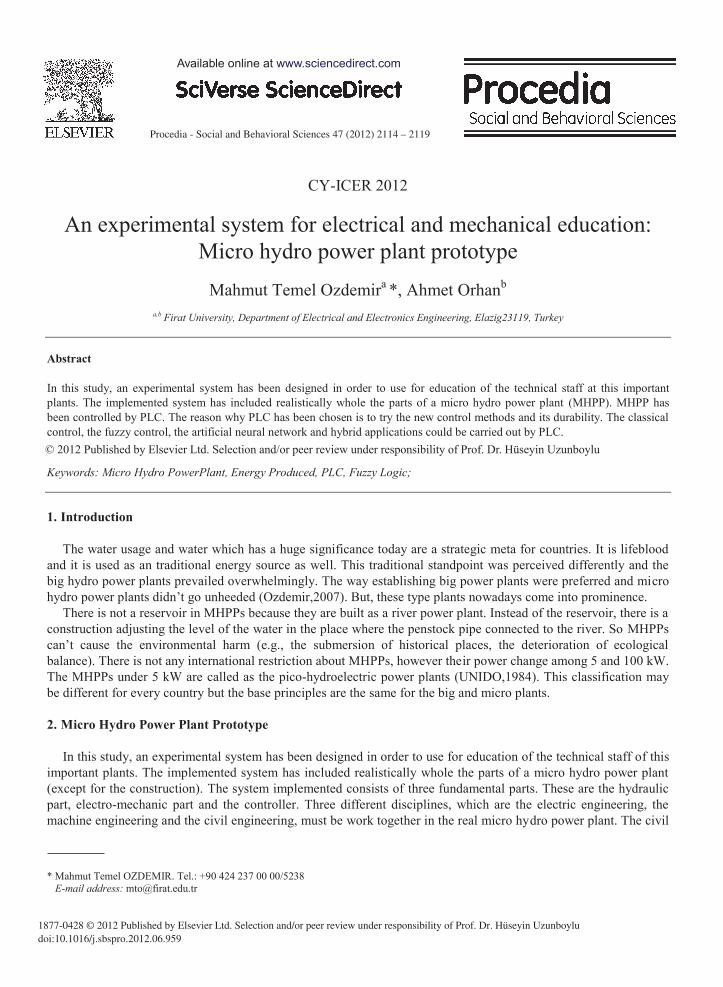
Figure 1. Scheme of the Micro Hydro Power Plant Prototype
2.1. Hydraulic Parts of Prototype MHPP
The work region of H (net head) and Q (flow rate) in the calculation is 107 meter and 7 liter/second, respectively. The dimension of some components was made by using of these values. The hydraulic part consists of motor driver, stage pomp, motor, pressure fixer and water tank. The other components are for the security of the system.
The water running the hydraulic power plant has definite pressure and flow rate. The water tank, the gradual pomp, the pressure fixer, the asynchronous motor and its driver exist in this part. The asynchronous motor operated by the driver drives the gradual pomp and this pomp transmits the water to pelton turbine with fix pressure. Pressure relief valve is used to fix the water pressure when water among increases or decreases. The mission of this pressure fixer is to provide the pressure change like those in real power plant. So, the sudden pressure changes caused by the load changes could be modeled.
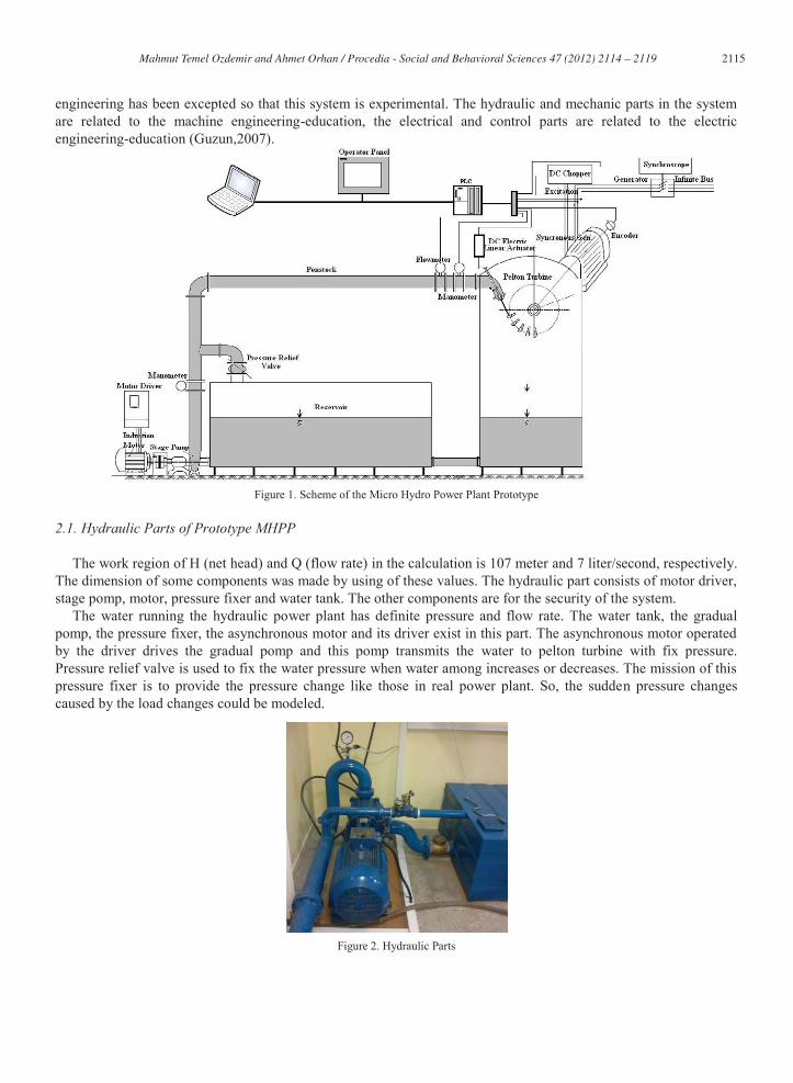
Figure 2. Hydraulic Parts
2116 Mahmut Temel Ozdemir and Ahmet Orhan / Procedia - Social and Behavioral Sciences 47 ( 2012 ) 2114 – 2119
2.2. Electromechanics Parts of Prototype MHPP
The system except for hydraulic parts is the same considerably as a hydraulic power plant. The water coming from the stage pomp transmits its energy to the turbine as mechanic energy via colliding and this water returns the water tank. Thus, the closed loop water circulation is achieved. The turbine drives the synchronous generator by this mechanic energy.
The frequency of output voltage of a synchronous generator is commensurate with the speed of rotate. So the flow rate can be controlled so that the frequency of generator can be controlled. Pressure-controlled systems are classically used for a control of flow rate in the hydraulic power system. The suggested solution in this system is to use a linear electrical activator. The flow rate control in this system has been done via linear activator which there is a needle at its peak. In any change of the rotate speed, the change of the water to be given to the turbine is provided by the back and forth movement of the needle.
The frequency of generator in the experimental system is calculated by two different units. The first is the data taken from encoder, which this is calculated by PLC, the second is calculated by microcontrolled- synchronoscope circuit capable of counting at the moment of zero passing of the voltage (Ozdemir,2009).
In large scale hydro installation Pelton turbines are normally only considered for heads above 150 m, but for micro hydro applications Pelton turbines can be used effectively at heads down to about 20 m.
Pelton turbines are horizontal axis and the one-two jets are produced. Many hydraulic machines such as the Pelton turbine is produced as a result of complex calculations and model experiments. Calculations used in the system of the turbine are designed based on simplified formulas (Eisenring,1991, Fraenkel,1991, Harvey,1993, Thake,2000).
According as the calculation given above, the main size of the pelton tribune is following as; d=1.42cm optimal jet diameter U=20.61 m/sn optimal peripheral velocity c1=43.98 m/sn absolute velocity of water jet b=4.41 cm bucket width h= 3.41 cm bucket height t=1.28 cm bucket depth Z=43 number of buckets D=39.38 cm pitch circle diameter (PCD) Da=43.48 cm outside diameter of runner nt= 1000 rpm Rotational speed of driven Since the manufacturing was made by local facilities, many troubles were encountered during the producing (for
example bucket width, height, depth number). In spite of these troubles, system was implemented successfully.
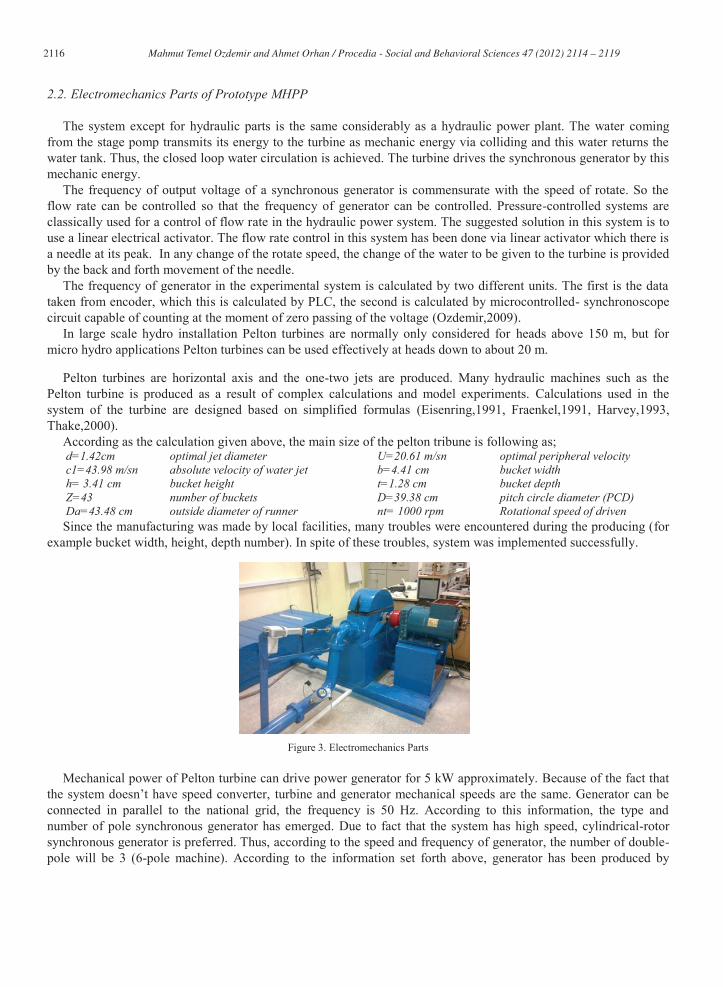
Figure 3. Electromechanics Parts
Mechanical power of Pelton turbine can drive power generator for 5 kW approximately. Because of the fact that the system doesn’t have speed converter, turbine and generator mechanical speeds are the same. Generator can be connected in parallel to the national grid, the frequency is 50 Hz. According to this information, the type and number of pole synchronous generator has emerged. Due to fact that the system has high speed, cylindrical-rotor synchronous generator is preferred. Thus, according to the speed and frequency of generator, the number of double-pole will be 3 (6-pole machine). According to the information set forth above, generator has been produced by
2117 Mahmut Temel Ozdemir and Ahmet Orhan / Procedia - Social and Behavioral Sciences 47 ( 2012 ) 2114 – 2119
manufacturer. the specific parameters of the generator are given below. The excitation of synchronous generator is designed for two different structures in accordance with educational material. These are rotating diodes (AC exciting) and slip ring (static exciting) structures.
S= 6,25 kVA Apparent power P= 5 kW Active power Q=3,75 kVAR Reactive power I=9 A Line Current UF/UH=231/400 V Phase-neutral/Phase-phase voltage ng= 1000 d/d , Speed f=50 Hz Frequency p=3 Number of double-pole ı cos = 0,8 Power factor Rotating Diode Excitation Slip-ring Excitation Uf= 39 V Excitation voltage Uf= 12 V Excitation voltage If=3,2 A Excitation current If=30 A Excitation current
2.3. Controller Parts of Prototype MHPP
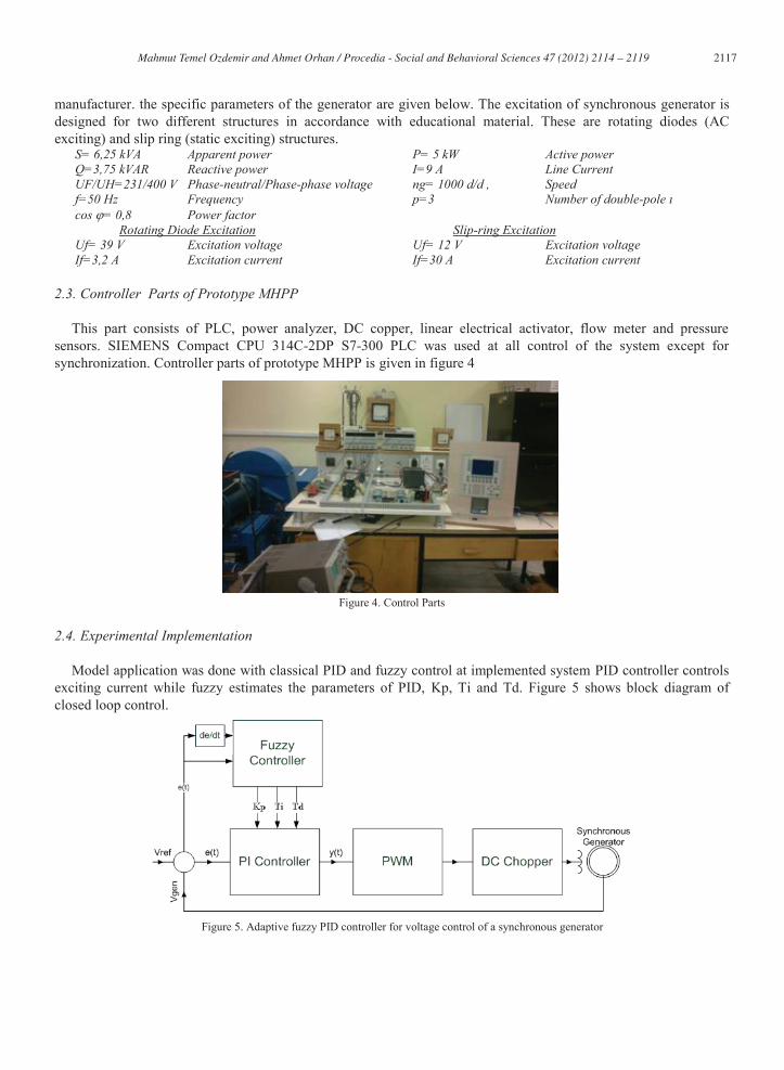
This part consists of PLC, power analyzer, DC copper, linear electrical activator, flow meter and pressure sensors. SIEMENS Compact CPU 314C-2DP S7-300 PLC was used at all control of the system except for synchronization. Controller parts of prototype MHPP is given in figure 4
Figure 4. Control Parts
2.4. Experimental Implementation
Model application was done with classical PID and fuzzy control at implemented system PID controller controls exciting current while fuzzy estimates the parameters of PID, Kp, Ti and Td. Figure 5 shows block diagram of closed loop control.
Figure 5. Adaptive fuzzy PID controller for voltage control of a synchronous generator
2118 Mahmut Temel Ozdemir and Ahmet Orhan / Procedia - Social and Behavioral Sciences 47 ( 2012 ) 2114 – 2119
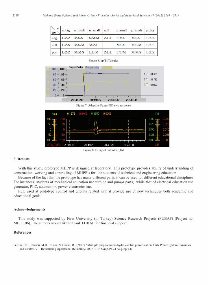
Figure 6. kp/Ti/Td rules
Figure 7. Adaptive Fuzzy PID step response
Figure 8. Fuzzy of output Kp,Kd
3. Results
With this study, prototype MHPP is designed at laboratory. This prototype provides ability of understanding of construction, working and controlling of MHPP’s for the students of technical and engineering education
Because of the fact that the prototype has many different parts, it can be used for different educational disciplines For instances, students of mechanical education use turbine and pumps parts, while that of electrical education use generator, PLC, automation, power electronics etc.
PLC used at prototype control and circuits related with it provide use of new techniques both academic and educational goals.
Acknowledgements
This study was supported by Firat University (in Turkey) Science Research Projects (FUBAP) (Project no. MF.11.06). The authors would like to thank FUBAP for financial support.
References
Guzun, D.B., Cazacu, M.D., Nistor, N.,Guzun, R., (2007). "Multiple purpose micro hydro electric power station, Bulk Power System Dynamics
and Control-VII. Revitalizing Operational Reliability, 2007 iREP Symp.19-24 Aug.,pp:1-8.

2119 Mahmut Temel Ozdemir and Ahmet Orhan / Procedia - Social and Behavioral Sciences 47 ( 2012 ) 2114 – 2119
Ozdemir ,M.T., Dağhan, İ.H, Orhan,A., Cebeci,M.,( 2007). Türkiye'nin Enerji Politikasında Küçük ve Çok Küçük Hidroelektrik Santrallerin Yeri
ve Önemi, İCANAS 38, 10-15 Eylül, Ankara, Türkiye. UNIDO, (1984)Small Hydro Power, Bulletin. Eisenring, M.,(1991). Micro Pelton Turbines, MHPG Series, Volume 9, St. Gallen: SKAT, and GATE: Eschborn, Fraenkel, P. , Paish, O. , Bokalders, V., Harvey A., Brown, A., Edwards R. (1991). Micro-Hydro Power: a guide for development workers,
London: IT Publications Ltd. Harvey,A.,(1993). Micro-Hydro Design Manual, London: IT Publications Ltd. Thake, J,(2000).The micro-hydro Pelton turbine manual: Design, Manufacture and Installation for Small-scale Hydropower, ITDG Publishing,
UK, pp 33-35. Özdemir, M.T., Orhan,A.,(2009). Senkron Generatörün Pic Mikrodenetleyicisi İle Paralele Alınması, TOK'09 Otomatik Kontrol Ulusal
Toplantısı YTÜ, 13-16 Ekim İstanbul, Türkiye