Embed Size (px)
Citation preview

Engineering, 2017, 9, 937-949 http://www.scirp.org/journal/eng
ISSN Online: 1947-394X ISSN Print: 1947-3931
DOI: 10.4236/eng.2017.911056 Nov. 27, 2017 937 Engineering
An Experimental Study on the Dissipation Effect of a Baffle Downstream of a Weir
Joon-Gu Kang
River Experiment Center, Korea Institute of Civil Engineering and Building Technology, Andong, South Korea
Abstract This study is an experimental study to analyze the dissipation effect of a baffle shape installed to reduce the scour problem downstream of a weir. The hy-draulic experiment on the flow dissipation effect created by baffle installation was an experiment under a fixed bed condition to investigate the flow dissipa-tion effect based on changes in flow in the apron downstream caused by changes in baffle shape. The experimental analysis was conducted by measuring the flow rate at the apron downstream with and without the installation of a baffle on the basis of the flow dissipation effect. This experiment compared the flow dissipation effect achieved with five baffle shapes to analyze the effect of the baffle shape. Two conditions of flow rate were considered: when a water level in the area of super-critical flow was lower than the baffle height, and when it flowed over the baffle. Overall, the flow dissipation effect was found to be good when a square baffle with a large flow blocking area was used. The analysis also found that hydraulic jump was facilitated when the front part of the baffle was inclined, as flow was induced to the upper direction. The result of the ex-periment showed that when performing flow dissipation through the use of a baffle, the effect of flow blocking and flow duration alteration should be con-sidered.
Keywords Weir, Scour, Baffle, Flow Dissipation
1. Introduction
A weir structure is established to enable water use and flood control, and con-sists of the main weir body wall and downstream apron. Since the River Design Criteria (RDC) were suggested based on general weirs constructed previously, there were technical limitations in the RDC with regard to designs of mid-sized
How to cite this paper: Kang, J.-G. (2017) An Experimental Study on the Dissipation Effect of a Baffle Downstream of a Weir. Engi-neering, 9, 937-949. https://doi.org/10.4236/eng.2017.911056 Received: October 10, 2017 Accepted: November 24, 2017 Published: November 27, 2017 Copyright © 2017 by author and Scientific Research Publishing Inc. This work is licensed under the Creative Commons Attribution International License (CC BY 4.0). http://creativecommons.org/licenses/by/4.0/
Open Access
J.-G. Kang
DOI: 10.4236/eng.2017.911056 938 Engineering
weir structures (fixed and movable weirs) [1]. In particular, in the RDC weirs were specified as small-sized structures whose height was up to 2 m to 3 m, which do not apply a flow dissipation structure against downstream flow. But in reality, heights of the installed weir structures are 5 m or higher, requiring flow dissipa-tion to stabilize a riverbed in the downstream, such as through dam structures. However, no downstream flow dissipation techniques have been applied to the design due to a lack of design criteria. Thus, various investigations on long-term risk factors are needed on the basis of the weir goal when a new flow dissipation technique is applied, but many technical factors have not been taken into consid-eration due to the limitation of scale of the local experimental facilities and the limited period of the experiment. Accordingly, problems of flood control and stability during weir operation have been reported in relation to the occurrence of scour in the upstream and downstream of the weir structure, decision making regarding the size of riverbed protection work, and maintenance after project completion.
Since there have been no previous studies conducted in Korea on the design of large-scale weirs, overseas scour protection and flow dissipation techniques were adopted without modification, and the technical level of technique devel-opment is relatively low. In addition, while a variety of studies on flow dissipa-tion work, size of weir downstream, and riverbed protection work are needed to maintain the riverbed stability in the weir downstream, most studies in Korea have concentrated on the size of scour and riverbed protection work. The Minis-try of construction & transportation national construction research institute per-formed an experimental study on size calculation of scour reinforcement in weir stream and proposed a calculation equation, but this was limited to a fixed weir related study [2]. The Korea Institute of Civil Engineering and Building Tech-nology performed an experimental study on the effect on hydraulic jump in the weir downstream, and proposed only a calculation equation that improved riverbed materials according to turbulence intensity in the hydraulic jump downstream [3].
Looking at overseas cases, various techniques on scour protection and flow dissipation in structures downstream have been proposed, but most of them re-late to dams downstream. Overseas studies on scour and riverbed protection work are as follows: McLaughlin Water Engineers investigated the advantages and disadvantages of various cross structures and proposed improved structures suitable for Denver City [4]. The agricultural research service presented the foun-dation based on hydraulic experiments conducted by Little and Murphy [5] [6]. Pilarczyk and Escarameia & May extended the experimental scope into gabion and concrete block protection work from the formula developed with regard to riprap, and proposed an improved universal relationship equation [7] [8]. Bijan performed a study evaluating scour depth through research on scour develop-ment at the apron downstream [9]. Urban Drainage and Flood Control District proposed a form of drop structure according to drop height and riverbed altera-
J.-G. Kang
DOI: 10.4236/eng.2017.911056 939 Engineering
tion in the downstream for drop structure design, and a design method that can be selectable based on control ability in the downstream, whether the riverbed is degraded, limit condition of the maximum drop height (0.9 m), accessibility by the general public, and design flow rate range to select the drop structure type [10]. In Korea and Japan, design criteria about lengths of apron and riverbed pro-tection work have been proposed. Various techniques of flow dissipation in the structure downstream have been proposed in Korea and abroad, but they are mostly applied to dams.
This study aims to analyze the effect of flow dissipation due to various baffle shapes for flow control in the weir downstream. To do this, the researchers con-ducted a hydraulic experiment with regard to the shape of flow dissipation work in the fixed weir downstream, measured the change in the flow rate and presented the effect based on the analysis.
2. Configuration and Method of the Experiment Devices 2.1. Configuration of the Experiment Devices
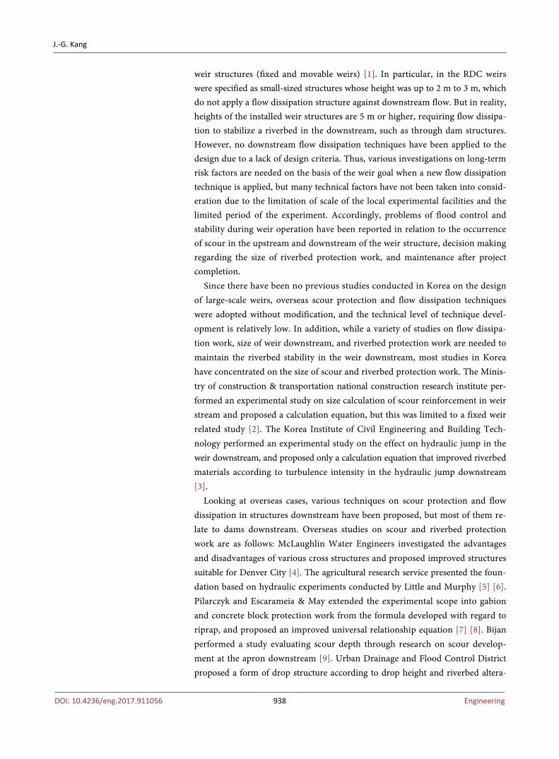
The experiment device used in the hydraulic experiment can be divided into a channel and flow supply unit. The flow supply unit was composed of underground storm water storage and pump, and the experimental device water channel con-sisted of baffle, model water channel, and downstream collecting well. The open channel used in the experiment device was installed to flow an amount of water up to 0.3 m3/s. The experiment water channel was designed in the River Test Center, and the specifications of the experiment water channel are as follows: flow supply capability was 0.3 m3/s, channel width was 1.5 m, channel length was 30 m and channel height was 1.2 m. The main sections of the experiment chan-nel were the weir, baffle installation area, experiment measurement area (alu-minum angle) and flow stabilization area (pebbles) (Figure 1). The weir in the
Figure 1. Ground plan of the straight channel.

J.-G. Kang
DOI: 10.4236/eng.2017.911056 940 Engineering
experiment was a basic shape whose width, height, and length were 1.5 m, 0.3 m, and 0.37 m, respectively (Figure 2). The baffles had five different shapes: square, round, equilateral triangle, trapezoidal, and stepped shapes. Figure 3 shows the baffle shapes and specifications.
To measure the change in flow that occurred due to the baffle installation, an experiment measurement area whose width and channel length were 2.0 m and 1.0m, respectively, was set up at the downstream of the baffle installation area. The measurement gap was marked every 10 cm in the horizontal and vertical direc-tions. There were 190 measurement points in total. The weir in the experiment structure was installed at a place where flow in the straight water channel was sufficiently uniform.
2.2. Hydraulic Experiment Method
A flow in the fixed weir downstream forms a super-critical flow due to a weir with a head drop, and hydraulic jump occurs in a certain area based on downstream
Figure 2. Experiment channel and weir for baffle effect.
Figure 3. Configuration and specifications of the baffle.

J.-G. Kang
DOI: 10.4236/eng.2017.911056 941 Engineering
water level and bed roughness. The location in the weir downstream where hy-draulic jump occurs is affected by the water level in the downstream. That is, when the water level in the downstream is lower, the location where hydraulic jump occurs becomes farther from the weir. When the location where hydraulic jump occurs becomes farther away, scour is more likely to occur at the apron down-stream, thereby affecting the weir’s safety. Thus, it is advantageous for riverbed safety to have hydraulic jump in the weir downstream occur inside the apron as much as possible. To determine this, in this experiment an energy dissipator (baf-fle) was installed at the weir downstream, forcibly generating hydraulic jump in-side the apron to analyze the effect in terms of maintaining the riverbed. To do this, flow rate, which was one of the main factors in this experiment, was measured at the downstream of the energy dissipator to verify the effect of the baffle’s shape. To compare the flow rate with and without the installation of a baffle, an expe-riment measurement area whose width and channel length were 1.0 m and 1.0 m was set up at the downstream of the baffle installation area. Figure 4 shows mea-surement equipment. For measurement equipment, a bogie with a size of 2.4 m × 0.4 m was installed to facilitate flow measurement at the upper end of the chan-nel, and a current meter was attached, which can be moved to the measurement area. The attached current meter was VO1000, a one-dimensional propeller current meter manufactured by KENEK in Japan. VO1000 can measure one-way flow rate and its measurement range was ±3 - ±200 cm/s, and measurement error was ±3 cm/s depending on the flow rate range. The measurement interval can be set to 5, 10, 20, 40, and 60 sec., and mean flow rate measured. In this experiment, the time interval was set to 20 sec. to measure mean flow rate. There were 21 ex-periment measurement areas, and a flow rate was measured at all 21 areas.
Two flow rate conditions were set to analyze the effect of flow dissipation due to the baffle arrangement in the weir downstream. The inflow rate conditions at the weir upstream were 0.140 m3/s and 0.325 m3/s, and the downstream water level conditions were 0.085 m and 0.140 m (Table 1). Table 2 presents an ar-rangement of baffle shapes in the fixed weir downstream applied to the experi-ment.
3. Experiment Results and Analysis
Table 3 presents the flow characteristics at the fixed weir downstream due to a
Figure 4. Propeller type current meter (left side) and bogie (right side).
J.-G. Kang
DOI: 10.4236/eng.2017.911056 942 Engineering
Table 1. Hydraulic experiment conditions.
Category Inflow rate
(m3/s) Upstream
water level (m) Downstream
water level (m) Baffle height
Case 1
0.140 0.390 0.085
Not installed
Case 2 Square shape
Case 3 Round shape
Case 4 Equilateral triangle
Case 5 Trapezoid
Case 6 Stepped shape
Case 7
0.325 0.440 0.140
Not installed
Case 8 Square shape
Case 9 Round shape
Case 10 Equilateral triangle
Case 11 Trapezoid
Case 12 Stepped shape
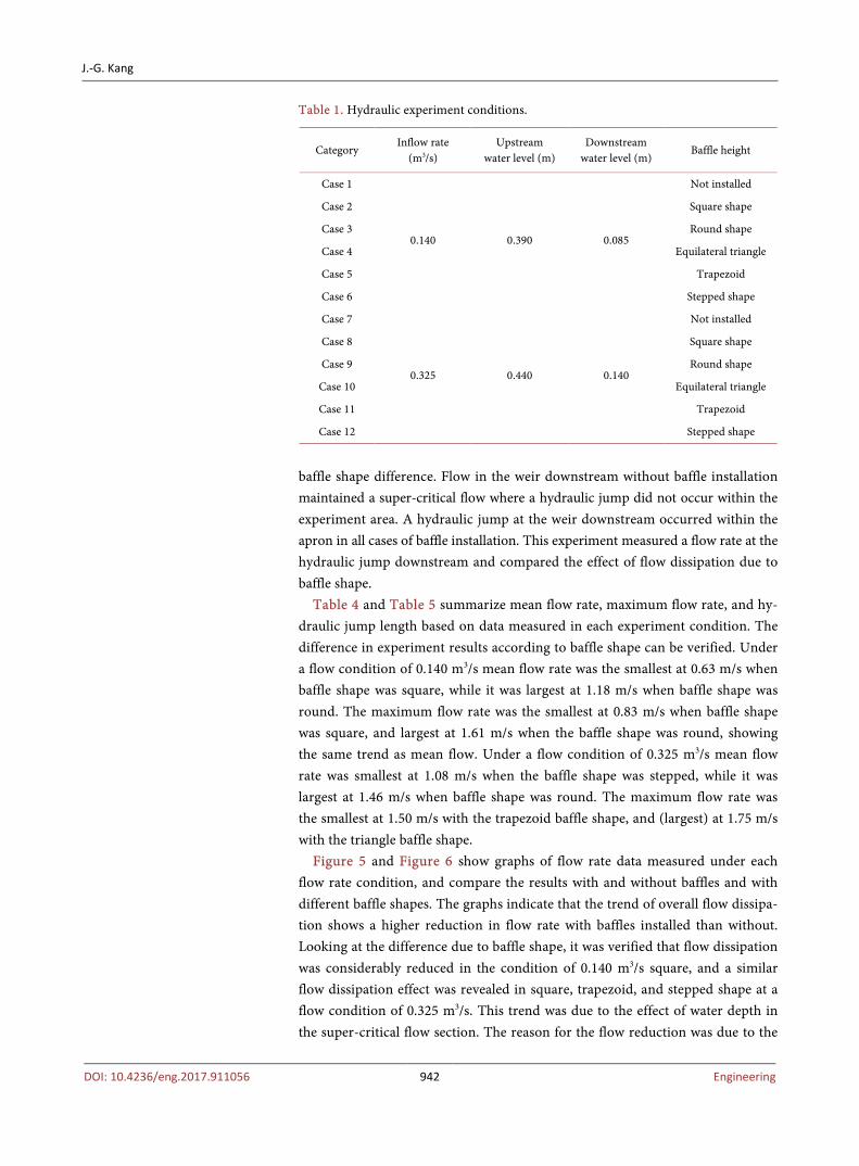
baffle shape difference. Flow in the weir downstream without baffle installation maintained a super-critical flow where a hydraulic jump did not occur within the experiment area. A hydraulic jump at the weir downstream occurred within the apron in all cases of baffle installation. This experiment measured a flow rate at the hydraulic jump downstream and compared the effect of flow dissipation due to baffle shape.
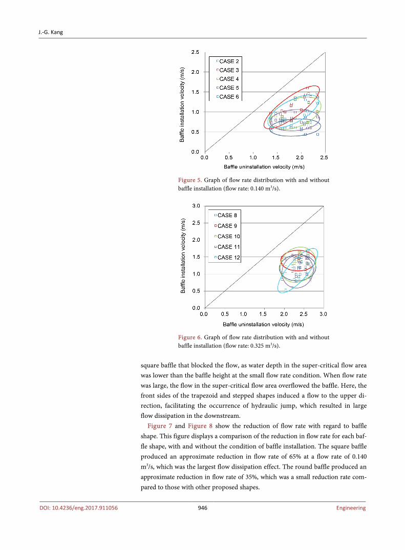
Table 4 and Table 5 summarize mean flow rate, maximum flow rate, and hy-draulic jump length based on data measured in each experiment condition. The difference in experiment results according to baffle shape can be verified. Under a flow condition of 0.140 m3/s mean flow rate was the smallest at 0.63 m/s when baffle shape was square, while it was largest at 1.18 m/s when baffle shape was round. The maximum flow rate was the smallest at 0.83 m/s when baffle shape was square, and largest at 1.61 m/s when the baffle shape was round, showing the same trend as mean flow. Under a flow condition of 0.325 m3/s mean flow rate was smallest at 1.08 m/s when the baffle shape was stepped, while it was largest at 1.46 m/s when baffle shape was round. The maximum flow rate was the smallest at 1.50 m/s with the trapezoid baffle shape, and (largest) at 1.75 m/s with the triangle baffle shape.
Figure 5 and Figure 6 show graphs of flow rate data measured under each flow rate condition, and compare the results with and without baffles and with different baffle shapes. The graphs indicate that the trend of overall flow dissipa-tion shows a higher reduction in flow rate with baffles installed than without. Looking at the difference due to baffle shape, it was verified that flow dissipation was considerably reduced in the condition of 0.140 m3/s square, and a similar flow dissipation effect was revealed in square, trapezoid, and stepped shape at a flow condition of 0.325 m3/s. This trend was due to the effect of water depth in the super-critical flow section. The reason for the flow reduction was due to the

J.-G. Kang
DOI: 10.4236/eng.2017.911056 943 Engineering
Table 2. Type of baffle arrangement.
Category Type of baffle arrangement Photo of baffle arrangement
Case 1
Case 2
Case 3
Case 4
Case 5
Case 6

J.-G. Kang
DOI: 10.4236/eng.2017.911056 944 Engineering
Table 3. Flow characteristics according to baffle shape (flow rate: 0.140 m3/s).
Category Flow characteristics (downstream) Flow characteristics (side)
Case 1
Case 2
Case 3
Case 4
Case 5
Case 6

J.-G. Kang
DOI: 10.4236/eng.2017.911056 945 Engineering
Table 4. Experiment result (flow rate: 0.140 m3/s).
Category Overflow
height (m) Baffle shape
Baffle arrangement
Mean flow rate
(m/s)
Maximum flow rate
(m/s)
Hydraulic jump
distance (m)
Case 1 0.09 Not
installed
Two-row straight
arrangement 1.855 2.340 1.348
Case 2 0.09 Square shape
Two-row straight
arrangement 0.629 0.833 0.200
Case 3 0.09 Round shape
Two-row straight
arrangement 1.177 1.607 0.200
Case 4 0.09 Equilateral
triangle
Two-row straight
arrangement 0.867 1.238 0.200
Case 5 0.09 Trapezoid Two-row straight
arrangement 0.801 1.004 0.200
Case 6 0.09 Stepped shape
Two-row straight
arrangement 0.957 1.321 0.200
Table 5. Experiment result (flow rate: 0.325 m3/s).
Category Overflow
height (m) Baffle shape
Baffle arrangement
Mean flow rate
(m/s)
Maximum flow rate
(m/s)
Hydraulic jump
distance (m)
Case 7 0.14 Not
installed
Two-row straight
arrangement 2.371 2.650 1.714
Case 8 0.14 Square shape
Two-row straight
arrangement 1.228 1.550 0.200
Case 9 0.14 Round shape
Two-row straight
arrangement 1.464 1.650 0.200
Case 10 0.14 Equilateral
triangle
Two-row straight
arrangement 1.364 1.745 0.200
Case 11 0.14 Trapezoid Two-row straight
arrangement 1.122 1.497 0.200
Case 12 0.14 Stepped shape
Two-row straight
arrangement 1.077 1.686 0.200
J.-G. Kang
DOI: 10.4236/eng.2017.911056 946 Engineering
Figure 5. Graph of flow rate distribution with and without baffle installation (flow rate: 0.140 m3/s).
Figure 6. Graph of flow rate distribution with and without baffle installation (flow rate: 0.325 m3/s).
square baffle that blocked the flow, as water depth in the super-critical flow area was lower than the baffle height at the small flow rate condition. When flow rate was large, the flow in the super-critical flow area overflowed the baffle. Here, the front sides of the trapezoid and stepped shapes induced a flow to the upper di-rection, facilitating the occurrence of hydraulic jump, which resulted in large flow dissipation in the downstream.
Figure 7 and Figure 8 show the reduction of flow rate with regard to baffle shape. This figure displays a comparison of the reduction in flow rate for each baf-fle shape, with and without the condition of baffle installation. The square baffle produced an approximate reduction in flow rate of 65% at a flow rate of 0.140 m3/s, which was the largest flow dissipation effect. The round baffle produced an approximate reduction in flow rate of 35%, which was a small reduction rate com-pared to those with other proposed shapes.

J.-G. Kang
DOI: 10.4236/eng.2017.911056 947 Engineering
Figure 7. Dimensionless coefficient range of flow rate according to baffle shape (flow rate: 0.140 m3/s).
Figure 8. Dimensionless coefficient range of flow rate according to baffle shape (flow rate: 0.325 m3/s).
The flow dissipation effect could be verified in the riverbed at the apron down-
stream by installing a baffle in all baffle shape conditions in this experiment. The result of the experiment showed that the square baffle had the best flow dissipa-tion effect considering the flow rate conditions applied. In the trapezoidal and stepped shapes, a phenomenon that induced the upstream flow into the upper direction when the flow was large was verified. Consequently, it facilitated a hy-draulic jump, thereby causing a large reduction in the flow rate at the riverbed in the downstream. This means that they can be highly applicable to weirs whose flow rate is large. The experiment result showed that flow dissipation through the baffle shape should be applied by considering the effect of flow blocking and flow duration alteration.

J.-G. Kang
DOI: 10.4236/eng.2017.911056 948 Engineering
4. Conclusions
This study is an experimental study that analyzes the flow dissipation effect pro-duced by the use of a baffle as a measure to minimize changes in the riverbed in the downstream of weir apron that result from scour. Five baffle shapes were se-lected, and the flow dissipation effect was analyzed through experimental measure-ment for each baffle shape.
The experiments were conducted under two flow rate conditions: 0.140 m3/s and 0.325 m3/s. The 0.140 m3/s flow rate condition involved a shallow water depth in the super-critical flow area in the baffle upstream. Here, the largest flow dissipa-tion effect was exhibited with the square baffles (approximately 65% flow dissipa-tion). At 0.325 m3/s flow rate with stepped shape condition, flow dissipation of ap-proximately 60% was revealed a good flow dissipation effect. The square baffle had large flow dissipation due to a large flow block effect because its flow blocking area was relatively larger than those of other shapes. In the trapezoidal and stepped shapes, a phenomenon that induced the upstream flow into the upper direction was verified at the condition where water depth in the super-critical area was dee-per than the baffle height. Consequently, it facilitated the occurrence of a hydrau-lic jump, thereby achieving a large reduction in flow rate at the riverbed. The experiment results showed that the square baffle provided a good flow dissipa-tion effect considering the flow rate condition. However, flow dissipation based on baffle shape must consider the effect of flow block and flow duration change when flow rate condition and size of weirs are taken into consideration.
Acknowledgements
This research was supported by the Korea Institute of Civil Engineering and Building Technology (Project title: Development of maintenance technology for enhancement of river water front and environmental values, Project number: 20170100).
References [1] Korea Water Resource Association (2009) The River Design Criteria. KWRA, Seoul.
[2] Ministry of Construction & Transportation National Construction Research Insti-tute (1996) Experimental Study on the Hydraulic Characteristics of River-Bed Maintenance Structure. KICT, Goyang.
[3] Korea Institute of Civil Engineering and Building Technology (2005) The Mul-ti-Function River Design Criteria. KICT, Goyang.
[4] McLaughlin Water Engineers (1986) Evaluation of and Design Recommendations for Drop Structures in the Denver Metropolitan Area. A Report Prepared for the Denver Urban Drainage and Flood Control District. McLaughlin Water Engineers Ltd., Denver.
[5] Agricultural Research Services (ARS) (1991) ARS Construction Project Design Standard Manual. 242.1. USDA, Beltsville.
[6] Little, W.C. and Murphey, J.B. (1982) Model Study of Low Drop Grade Control Structures. Journal of the Hydraulics Division, 108, 1132-1146.

J.-G. Kang
DOI: 10.4236/eng.2017.911056 949 Engineering
[7] Pilarczyk, K.W. (1990) Stability Criteria for Revetments. Proceedings of the 1990 National Conference on Hydraulic Engineering, San Diego, 30 July-3 August 1990.
[8] Escarameia, M. and May, R.W.P. (1992) Channel Protection: Turbulence Down-stream of Structures. Report SR 313. Hydraulics Research Ltd., Wallingford.
[9] Bijan, D. (2003) Scour Development Downstream of a Spillway. Journal of Hydrau-lic Research, 41, 417-426. https://doi.org/10.1080/00221680309499986
[10] Urban Drainage and Flood Control District (2008) Drainage Criteria Manual Vol. 2. City of Colorado Springs Engineering Division, Colorado.