Embed Size (px)
Citation preview
1957 Bender and Hercules: The Transfer Function of a Rate Gyro 35
The principal source of background noise of the in- current is approximately one-fourth of that from air-strument system is that caused by light scattering of scattering. The contribution to the total random noisethe air molecules in the 3 X3 X 1 mm sensitive volume. by the preamplifier is negligible. It has been determinedThis phenomenon produces a constant background experimentally that decreasing the sensitive volume (bylevel of light flux at the photocathode. The resulting decreasing the slits) decreases the air-scattering noise,dc phototube current has superimposed upon it a but not enough data has been obtained as yet to de-random ac component due to shot-effect, the ac com- termine the exact relationship between the two.ponent causing the noise. While the peaks of this noiseare of larger amplitude than pulses from a 1.0 micron ACKNOWLEDGMENTparticle, they are not registered as the noise spikes areof much shorter duration than the signal pulses and are The autbors wish to acknowledge contributions to theeffectively filtered by the noise-filtering gate of the aerosoloscope electronic instrumentation program madetrigger generator. The gain of the system can be in- by: J. N. Van Scoyoc, who aided in a technical capacity;creased by a factor of from 2.5 to 3.5 before the output J. L. Murphy, who contributed some of the ideas in thenoise due to air scattering is of a value great enough to formative stages; and R. Purcell, who did the construc-be registered. The noise caused by the phototube dark tion and assembly work on both of the instruments.
An Experimental Method for Obtainingthe Transfer Function of a Rate Gyro
M. BENDERt AND F. P. HERCULES:
DEFINITION OF A GYROscoPIc ELEMENT
GYROSCOPIC element is a system of charac-teristics as follows:1) Nonpendulous with freedom to rotate abouta point,2) a symmetrical body spinniing at a constanthigh rate about its axis of symmetry, and3) all angular momentum of system is effectivelyconcentrated about spin axis.
FUNDAMENTAL PRINCIPLE OF THEGYROSCOPIC PHENOMENON I\
1) What is the Gyroscopic Phenomenon? C . D
The classical example of exhibiting the effect is bymeans of a gyroscopic element mounted in a Cardan's5suspension. This provides mounting of a body so as tofix only one point. Fig. 1 shows a Cardan suspension.The gyro element is represented by the inner figure.X XPoints A and B are fixed. R1 and R2 refer to the gimbal +rings (or gimbals). Masses of the rings are very muchless than mass of the gyro element. R1 rotates about AB.e=This is one degree of freedom. R2 rotates about CD,giving a second degree of freedom. The gyro elementrotates about EF, giving the third degree of freedom. B
* Manuscript received by the PGI, December 23, 1955.t Atomic Power Div., Westinghouse Corp., Bettis Field, Pitts--_________________
burgh, Pa.; formerly with McDonnell Aircraft Corp., St. Louis, Mo.t Missiles Eng. Div., McDonnell Aircraft Corp., St. Louis, Mo. Fig. 1-Cardan's suspension.
36 IRE TRANSACTIONS ON INSTRUMENTATION March
The element can take up all positions in which the point and its rate of change isO of the element is fixed in space, 0 being a commonintersection of EF, CD and AB. h = Q X h X laSPi (4)
If the gyro element is at rest, and a couple is appliedto the AB axis on the shafts of R1 in either direction in Thus, the gyroscopic couple, C, required to maintainthe plane of the paper, the EF axis remains in the plane the motion isof the paper; the entire system moves in accordance 4 =with the expected result. G = IasPi, (5)But if the gyro element is spinning at a constant high that is, a couple of magnitude Ia sp produced by a pair
rate about its axis of symmetry, the EF axis, say in a of forces in the rotating plane of j and k.counter-clockwise direction, and the couple is applied Then the fundamental law of the gyroscope isas before, say in a counter-clockwise direction, the EFaxis rotates about the CD axis. Point E comes out of the G > (plane of the paper, and point F goes inward. If the G Q X h (6)couple displaces the AB axis by 900 counter-clockwise, which is Newton's second law of motion in rotationalthen the EF axis lies in a plane perpendicular to the form.plane of the paper.
It is this surprising motion of the gyro element that FUNDAMENTA POERES,is known as the "gyroscopic phenomenon" (or "gyro- APPLICATIONS THEREOFscopic effect"); this motion is called precession, and is a 1) A Means for Obtaining a Reference Line in Inertialquantity of precessional angular velocity. Space
The law of the gyroscope is reversible; that is, a
torque input results in angular velocity output (pre-Consider the gyro element isolated from its suspen- cession), and an angular velocity input (forced preces-
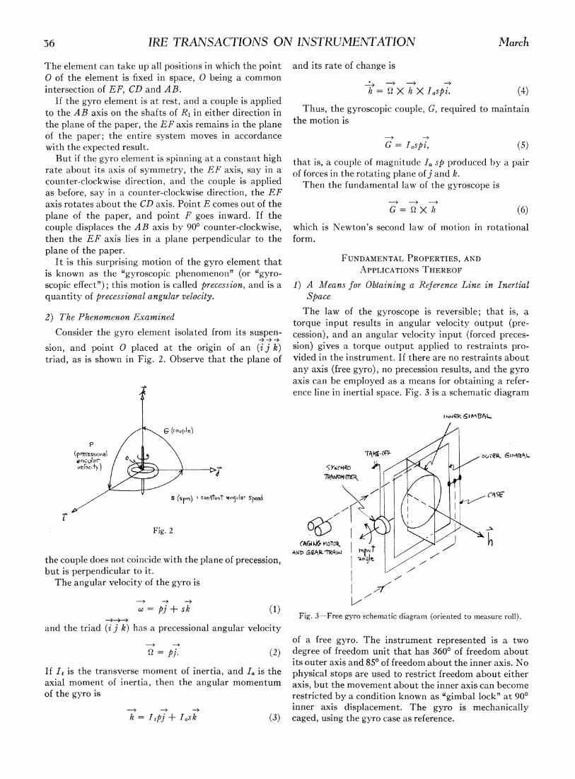
sion, and point 0 placed at the origin of an (ij k) sion) gives a torque output applied to restraints pro-triad, as is shown in Fig. 2. Observe that the plane of vided in the instrument. If there are no restraints about
any axis (free gyro), no precession results, and the gyroaxis can be employed as a means for obtaining a refer-ence line in inertial space. Fig. 3 is a schematic diagram
INNi 6 M It3L
(cOuJ ie)Ve[O >jX ~~~~~~~~~~~~~~~~~~SY4ce1RO ;(PrecessS co,ot, -81 SMaA -
C,~~~I(sp,n) - o- Spela-Haxw
Fig. 2CAG4 1&XfrOTc> I/
ATWD GE.P I1k/the couple does not coincide with the plane of precession, I -,but is perpendicular to it.The angular velocity of the gyro is 7
X=pj + sk (1)Fig. 3-Free gyro schematic diagram (oriented to measure roll).
and the triad (i j k) has a precessional angular velocityof a free gyro. The instrument represented is a two
Q= pj. (2) degree of freedom unit that has 3600 of freedom aboutits outer axis and 85° of freedom about the inner axis. No
If It is the transverse moment of inertia, and Ia is the physical stops are used to restrict freedom about eitheraxial moment of inertia, then the angular momentum axis, but the movement about the inner axis can becomeof the gyro is restricted by a condition known as "gimbal lock" at 900
__< inner axis displacement. The gyro is mechanicallyh = Itpj + Iask (3) caged, using the gyro case as reference.

1957 Bender and Hercules: The Transfer Function of a Rate Gyro 57The free gyro is employed where displacement from angular displacement by feeding the output into an
some specific reference attitude is desired. The gyro is elastic restraint. A gyro employed in this manner isuncaged when the particular attitude is attained, and termed a "rate gyro"; Fig. 6 (niext page) is a schematicthereafter the displacement from that position is indi- diagram of such an instrument.cated by the take-off. The transfer characteristic of the rate gyro is readilyThe normal operating orientation of the spin axis de- obtained from a straightforward consideration of the
pends upon the application; for example, in a vertical equation of motion of the single gyro gimbal, whose axisgyro, the spin axis is maintained vertical; in a direc- is the output axis of the device, and may be writtentional gyro, it is maintained horizontal. Applications of I + c
± k I,Q2i = hwi (7)the nature described above arise in connection withmissile stabilization and guidance. Fig. 4 is a functional whereblock diagram of a free gyro. The synchro pick-off of 1o= moment of inertia (slug-ft2) of gimbal suspensionFig. 4 is represented by Kp, and is shown schematically about output axis,in Fig. 5. The rotor of the transmitter only is excited, Oo=angular displacement (radians) of gimbal about
output axis,APPARF-Nr DRIFT co=viscous damping coefficient about output axis
RATE IWSTt Kp e0 (lb-ft/rad/sec),: K=OTPUT voLTAG K=restoring spring constant (lb-ft/rad) about out-li %fR PICkoFf put axis,
SNSITVIT>' I=moment of inertia (slug-ft2) of gyro wheel about(Vo t.TVRAA4N) spin axis,
-RFE GM, xi = Oi = angular velocity of gyro case about input axisFu4C1IQfN L 'BOCK IAGRPM (rad/sec),
ea h=I Q=angular momentum of gyro wheel (slug-ft2/sec).
Eq. (7), in operational form, isFig. 4
Co K) (hrOtd>tll ts~~~~~~~~~~~2+-s +- 00 =-s) i (8)rotorit 1s,6 .(8
Let
Wn4/(9)
the natural frequency of the gyro gimbal suspensionabout the output axis. Then, for critical damping,
CO = 2-/KIo . (10)
The damping ratio, i, is the ratio of actual damping to
**Or -vtta 4eAi - case critical damping, orFig. 5 co Co
Ccrit 2V1(KIOits rotation causing a rotation of the induced magnetic From (9)field axes in the stators of both synchros. The rotor ofthe receiver synchro is mechanically locked and no ap- K = W"2Io. (12)preciable current is drawn from it, so its induced voltage -Substituting (12) into (11), thenis a function of the angular position of the transmitterrotor on the gyro gimbal. co - co
2) A Means for Measuring Angular Velocities with Re- 2 V10wfl210 2IoW@spect to Inertial Space and the second term of the left member of (8) becomes
The law of behavior of the gyroscope indicates that can input of angular velocity will yield a torque output. -,= 20,(13)In a single degree of freedom (one axis restrained) gyro,this output torque is converted proportionally to an awnd the third is w,n2.
38 IRE TRANSACTIONS ON INSTRUMENTATION March
INPUT AXIS
case
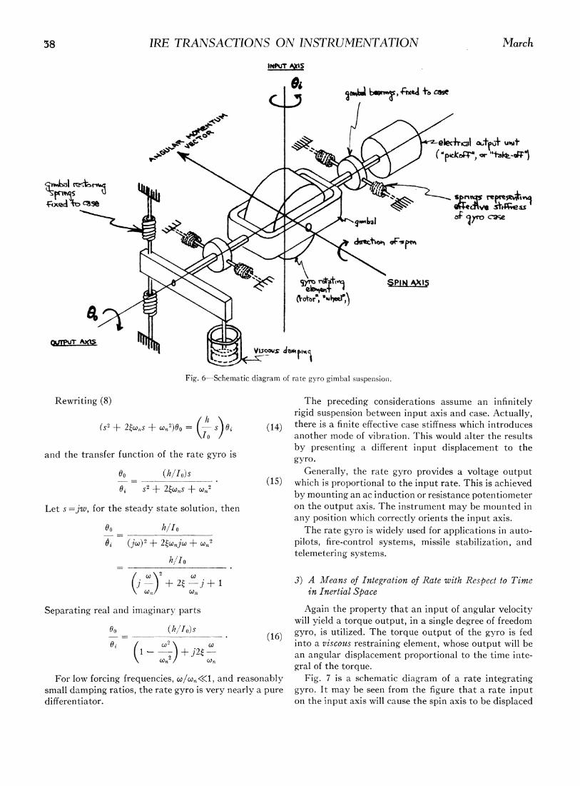
Fig. 6-Schematic diagram of rate gyro gimbal suspension.
Rewriting (8) The preceding considerations assume an infinitelyrigid suspension between input axis and case. Actually,
(s2 + 20w,s + w2)0o = s Oi (14) there is a finite effective case stiffness which introduces\I0 / another mode of vibration. This would alter the results
by presenting a different input displacement to theand the transfer function of the rate gyro iS gyro.
do (h Io)s Generally, the rate gyro provides a voltage output-i -2 + 2ic.> S + @ 2 (15) which is proportional to the input rate. This is achieved
6. f2 + 2~w?~5 + ~2 by mounting an ac induction or resistance potentiometer
Let s =jw, for the steady state solution, then on the output axis. The instrument may be mounted inany position which correctly orients the input axis.
6o h/Io The rate gyro is widely used for applications in auto-(jW)2 + 24njoj + W 2 pilots, fire-control systems, missile stabilization, and
hIlo telemetering systems.
(j-) + 24-j + 1 3) A Means of Integration of Rate with Respect to Time()Jn Ci)n in Inertial Space
Separating real and imaginary parts Again the property that an input of angular velocitywill yield a torque output, in a single degree of freedom
(h/Io)s______-. (16) gyro, is utilized. The torque output of the gyro is fed
f9i / wJ2\0Co) into a viscous restraining element, whose output will be
k\t X)+2} X an angular displacement proportional to the time inte-gral of the torque.
For low forcing frequencies, o,/wUn«l, and reasonably Fig. 7 is a schematic diagram of a rate integratingsmall damping ratios, the rate gyro is very nearly a pure gyro. It may be seen from the figure that a rate inputdifferentiator. on the input axis will cause the spin axis to be displaced

1957 Bender and Hercules: The Transfer Function of a Rate Gyro 59
from its original reference; this displacement is caused dynamic surfaces. Limitations in the performance of
by the torque which arises from hXO, the angular this function arise from mechanical imperfections such
momentum of the gyro wheel crossed into the input as undesirable torques due to imbalance in the gimbalangular velocity. This torque is opposed by the torque suspension, bearing friction and other structural aber-of the viscous damper, which is Coo,where is the re rations.of turn of the output axis. A classification of gyroscopic instruments based on
the fundamental properties of the phenomenon seemsto be the most natural and would be as follows:
s / ^ ~PICK-OrFtPIKOz ,/1) Two degrees of freedom (two gimbals).Angular position input (free gyro).
OUT1PUTNER GBA 7 2) Single degree of freedom (one gimbal).
SPIN AxIs (MoTloN Angular velocity inputs-torque outputs.CAUS1:)I BY IN-
TOR9UER1/ PUT TORQUE) a) rat yro-elastic restraint (with or without;b; off
h damp).
(,,rURM RAT XPIIAAXIN b) rate integrating gyro-viscous restraint.'TAM.NPUT INPIJTA Is
D$MF'R EXPERIMENTAL METHOD FOR OBTAINING THE TRANSFER
Fig. 7-Schematic diagram rate integrating gyro. FUNCTION OF THE RATE GYRO
The purpose of such an investigation is to obtain first-Then hand quantitative information about the sensitivity,
rt_d=o linearity, damping ratio, and natural frequency.CO J d = co(oot -Soto) Sensitivity and linearitv comprise static calibration
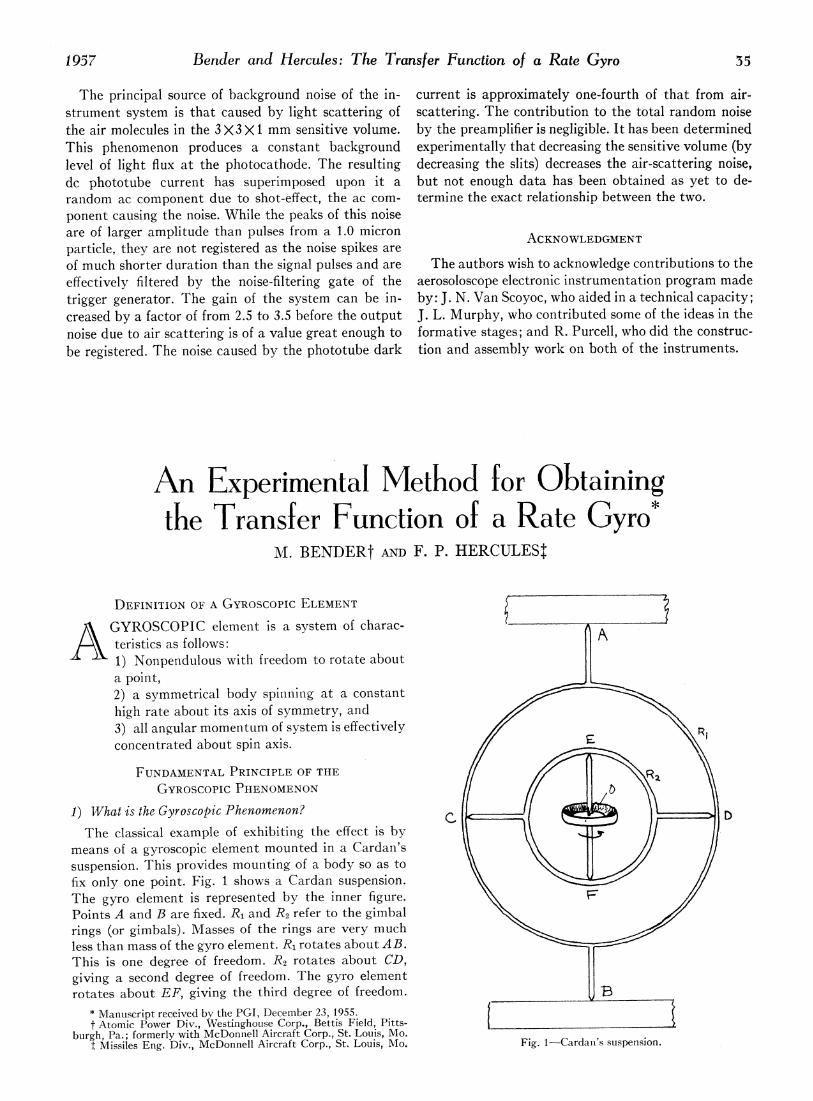
data, and may be obtained by rotating the gyro aboutwhich is a net output axis displacement during two suc- its input axis on a rate-of-turn table. If the electricalcessive intervals of time. Any further rate inputs will output is plotted vs a sequence of rates for both clock-cause additional displacements, and will be summed wise and counterclockwise rotations, the slope of theover the time the inputs occur. The above is particu- resulting curve gives the sensitivity of the instrumentlarly true of a system with a very small time constant, in volts, rms/degree/second (assuming ac for pick-offand for low forcing frequencies. excitation).
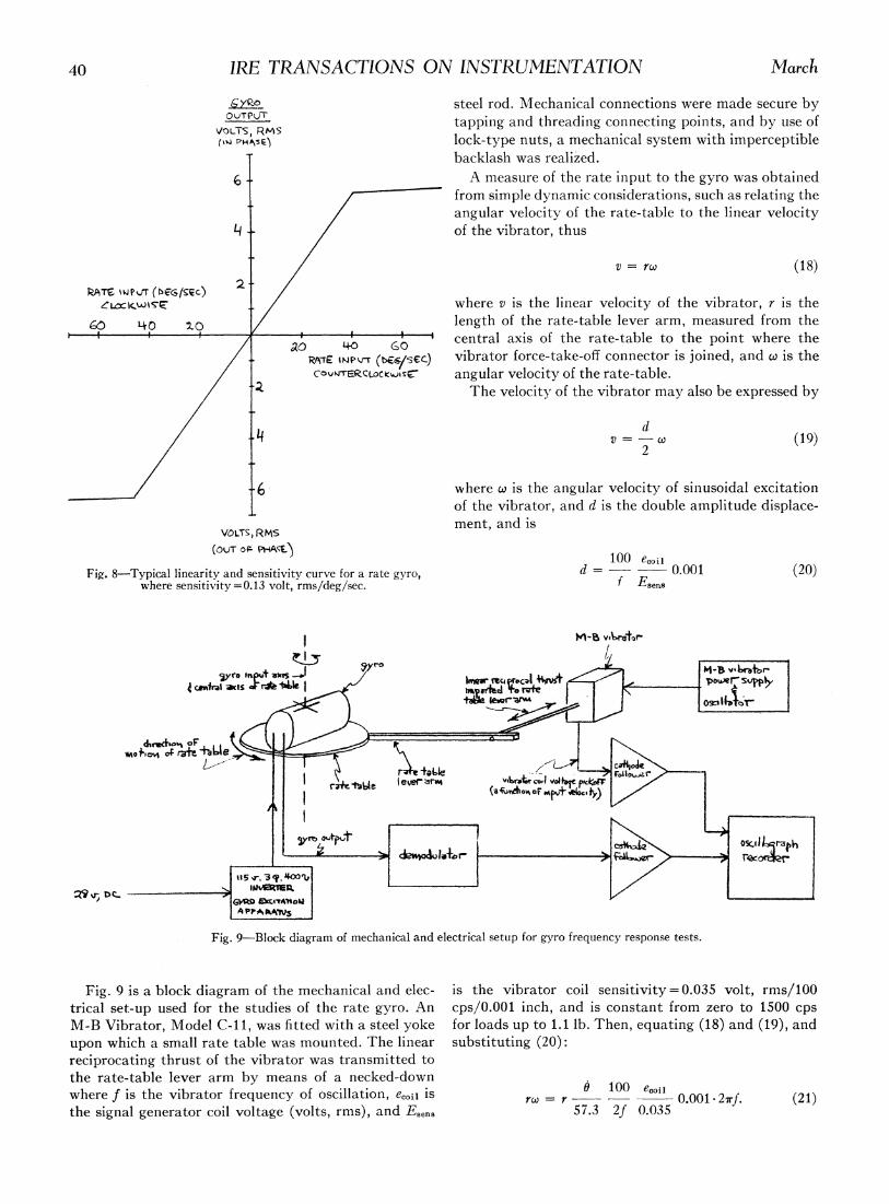
This type of gyro is sometimes known as a torque- Fig. 8 is a typical linearity-sensitivity curve for asumming computer (input turning rates are converted rate gyro. The limit of the range of rate-input and theinto torques that are time-integrated into gimbal dis- linearity of the output over the range may be seen fromplacements through a viscous fluid). A signal which is this curve.proportional to angular displacement is taken from a In order to write the transfer function for the ratepick-off on the output axis. gyro, which is, in general
Typical applications of the rate integrating gyro arespace stabilization and rate-tracking. In space stabiliza- 00 1tion, the output signal is amplified through a high gain i S2 I+ 20c,,s + n
(17)servo amplifier to a servo motor which repositions theplatform. In this application no input current is applied the damping ratio, (, and the natural frequency, wn,to the torquer. Angular displacement information can must be measured. This may be accomplished throughbe obtained from a pick-off on the platform. In rate- the frequency response method, which is based on thetracking, a platform is required to move at a specified fact that quantities varying with time can be mathe-rate. When used in this manner, an input current propor- matically represented by the superposition of a set oftional to the desired rate is introduced into the torquer sinusiodal time variations with appropriate amplitudes,mounted on the output axis of the gyro. frequencies, and phases. The behavior of a given rate
gyro is then analyzed by studying its reaction to pureGYROSCOP1C INSTRUMENTS AS CONTROL ELEMENTS sinusoidal mechanical oscillations of various frequencies.
The function of gyroscopic instruments in controlling Once the parameters, natural frequency and dampingthe motion of airborne vehicles is to convert quantities ratio, are measured, and the transfer function written,which are characteristic of motion with respect to the effect of a signal of any arbitrary time dependenceinertial space coordinates, such as angular displacements can be calculated.and angular velocities, into signals which can be The authors have measured several rate gyros withutilized by electronic gear to provide actuation of aero- good results using the technique described below.
40 IRE TRANSACTIONS ON INSTRUMENTATION March
steel rod. Mechanical connections were made secure by0UTfPUJT tapping and threading connecting points, and by use ofL RMH5 lock-type nuts, a mechanical system with imperceptible
backlash was realized.6 - . A measure of the rate input to the gyro was obtained
from simple dynamic considerations, such as relating theangular velocity of the rate-table to the linear velocity
4j - /of the vibrator, thus
v=vrc (18)
RATS %WP fT (bEG/gec)exL'CKWiTz /where v is the linear velocity of the vibrator, r is the
4;o 40) Iz0 /length of the rate-table lever arm, measured from theI' ' ' /I ao 40 GO central axis of the rate-table to the point where the
/ PssTs zfiNPJ (b6./sEL) vibrator force-take-off connector is joined, and X is theCoviECLocaUsC, angular velocity of the rate-table.
The velocity of the vibrator may also be expressed by
/r4 v =dw-X (19)2
where X is the angular velocity of sinusoidal excitationof the vibrator, and d is the double amplitude displace-ment, and is
100 e,OiiFig. 8-Typical linearity and sensitivity curve for a rate gyro, d =- 0.001 (20)
where sensitivity = 0.13 volt, rms/deg/sec. f Esens
I m-a
~~~~cy ipAauotos --J _61eo i 11
is J_1Bl levferare lmiewM °F*C *y) |/-M 1an- V
iewr'arvA1- vA64o
4rI ever | IF Ca, l
A PPAkV
L~
Fig. 9-Block diagram of mechanical and electrical setup for gyro frequency response tests.
Fig. 9 is a block diagram of the mechanical and elec- is the vibrator coil sensitivity=0.035 volt, rms/100trical set-up used for the studies of the rate gyro. An cps/0.001 inch, and is constant from zero to 1500 cpsM-B Vibrator, Model C-li, was fitted with a steel yoke for loads up to 1.1 lb. Then, equating (18) and (19), andupon which a small rate table was mounted. The linear substituting (20):reciprocating thrust of the vibrator was transmitted tothe rate-table lever arm by means of a necked-downwhere f is the vibrator frequency of oscillation, e00il is rc 100 e00oi 12f()the signal generator coil voltage (volts, rms), and Esens 57.3 2f 0.035 001.2. (1
1957 B3ender arnd Hercules: The Transfer F'urnction of a Rate Gyro 41
SiZX- 4A
~o4} XPM$-- -t I -_
0 l
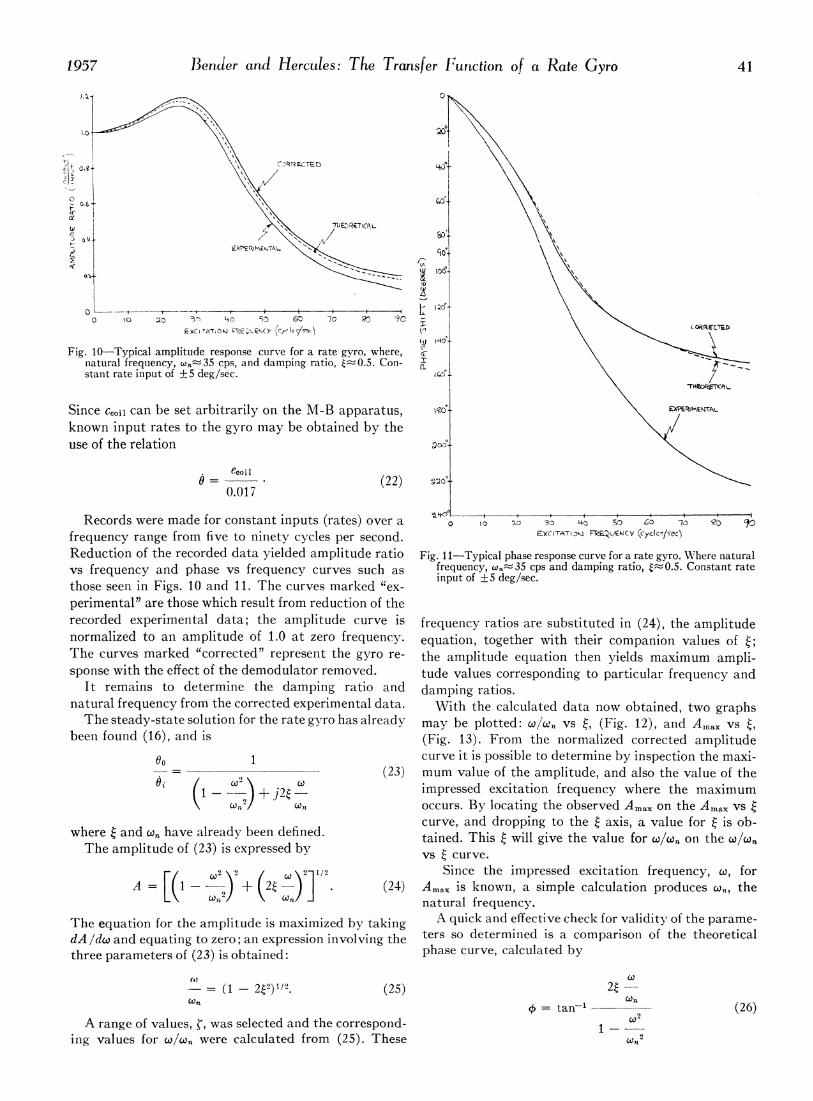
Fig. 0Typical amplitude response curve for a rate gyro, where, \natural frequency, co,nr35 cps, and damping ratio, t~.5 Con- a'\stant rate input of ±+5deg/sec. I°*\j
Since cCO0u can be set arbitrarily on the M-B apparatus, wg IEAknown input rates to the gyro may be obtained by the <use of the relation a
0 (22) a°0.017
Records were made for constant inputs (rates) over a t O -~ ,'S w 0 42 S 5ffrequency range from five to ninety cycles per second. EyI~T^XiFW 0CY (cyckj8sec)Reduction of the recorded data yielded amplitude ratio Fig. 11-Typical phase response curve for a rate gyro. W;here naturalvs frequency and phase vs frequency curves such as frequency, x~n~35 cps and damping ratio, tnO0.5. Constant ratethose seen in Figs. 10 and 11. The curves marked "ex- input of ±5deg/sec.perimental" are those which result from reduction of therecorded experimental data; the amplitude curve is frequency ratios are substituted in (24), the amplitudenormalized to an amplitude of 1.0 at zero frequency. equation, together with their companion values of t;The curves marked "corrected" represent the gyro re- the amplitude equation then yields maximum ampli-spouse with the effect of the demodulator removed. tude values corresponding to particular frequency and
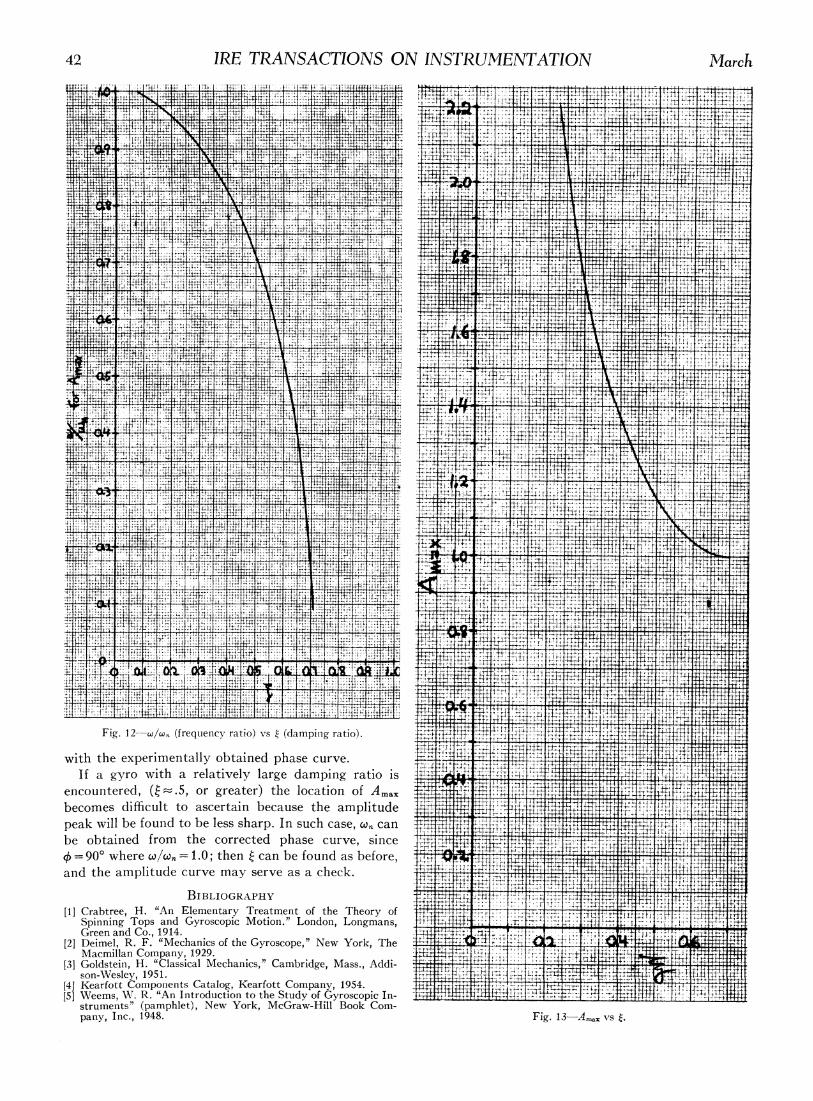
It remains to determine the damping ratio and damping ratios.natural frequency from the corrected experimental data. With the calculated data now obtained, two graphsThe steady-state solution for the rate gyro has already may be plotted: wjo.' vs t, (Fig. 12), and Amax vs i
been found (16), and is (Fig. 13). From the normalized corrected amplitude00 ~~1 curve it is possible to determine by inspection the maxi-= ~~~~~~(23)mum value of the amplitude, and also the value of the
e (1---+_ (i. impressed excitation frequency where the maximum+£n J2(Cn occurs. By locating the observed Amax on the Amax vs
curve, and dropping to the t axis, a value for t is ob-where t and w,. have already been defined, taed Ths'wl ietevlu o /, nteoThe amplitude of (23) is expressed by vs curve.
F! (1,2 \2 / wt\2]i/2 Since the impressed excitation frequency, co, forA= LK1 _ )} + (20-)~ (24) Ama1 is known, a simple calculation produces wn, the/v Un natural frequency.
The equation for the amplitude is maximized by taking A quick and effective check for validity of the parame-dA/dw and equating to zero; an expression involving the ters so determined is a comparison of the theoreticalthree parameters of (23) is obtained: phase curve, calculated by
-= (1 - 22)il2. (25) 24Xn Up ~~~~~~~~~~~=tan'1co (26)
A range of values, ~, was selected and the correspond- 1-@inlg values for co/wa were calculated from (25). These Won2
42 IRE TRANSACTIONS ON INSTRUMENTATION March1-4
-4.:44,4444-4- + 4i4+-
4: -T 4.4 ';4 -
4 T I4
Ij T, L- 4-1
0. + ,4` H 41
_4T
7
TA. + I ,j-J:. -
4- 4 t -t09 I-F -qi,+: 444 Z,.- 4
-4 4
+ 14-T P- t4, 4.- 7
14 -4 4-JF4444
.4 .4- J--4 4
+
4V 4,.4
I t,4v .V2-
t:: Tiri H -4-:4i t. 1, Ti.
+4
4,T -jH T. +-Tj + il-- I
I.- .+4 4 -l' MLd, t -T, ;47' TT::-4- 41
tt, i4V+ +
-41 -T-T t
.L.4 .4-14- I 4; .H 4t
t
-W.j. -.E -;TT 4-4
Ti 4.-H4
4- -4-T
T: 04t Tji Tq,. #4-1 -+ ,
tt: -4i: ji ..a t..' 4rl. :+1J. 'Tii+TT:
4-T.'. T, + +
ti 4. t4-
1, L .1 -, -1, _;_. - 44-4-
i---4iv 117.-4 4
it ;O.i
4,T I 1.i-ll -,V :11P.&W4. T,
T4; 1.:-4 +4
-qT
Z:r, 172. -T- -I+'`4
-4 + + T-Z;.4 i-iif I 4
i,V S
14-41 L .-:1 1-14 T
Ti-LTA
411i T.4 T
4 'M7;4 1-
TTN + 4+m Trt, T
H+
'F
a
177.-Tj 4
4 44 4i::71:
r -T
rt T+,
_j7 !,P,. M7-7 .4
7
+
4. 4. .H, i.-- tc t
J1 -t-T-TT+T
.4 It filT t
t:+ri
A41-4- 4-4 +:V +
-T -r ttr
4tj+TT! -.1i ,HT
4 +4.i 4.Fig. I 2-wlw,, (frequency ratio) -,,-s (dampiiig ratio). +-4-T-: '44
:,,4 +
+-T 4 twith the experimentally obtained phase curve. I
if a gyro with a relatively large damping ratio is 4V.4'1- .'Ij-4
encountered, Q .z--.5, or greater) the location of Am,xI Tbecomes difficult to ascertain because the amplitude T- ITr-- + A
peak will be found to be less sharp. In such case, w,,, cant -t T 4-
.4 4-, -1be obtained from the corrected phase curve, sincet t90' where colco,, 1.0; then can be found as before, 1-V
L Land the amplitude ctirve may serve as a check. 4t -L
4 +1