Embed Size (px)
Citation preview
This is an Open Access article distributed in accordance with the Creative Commons Attribution
Non Commercial (CC-BY-NC-ND 4.0) license, which permits others to copy or share the article,
provided original work is properly cited and that this is not done for commercial purposes. Users
may not remix, transform, or build upon the material and may not distribute the modified material
(http://creativecommons.org/licenses/by-nc/4.0/)
Trivent Publishing
© The Authors, 2016
Available online at http://trivent-publishing.eu/
Engineering and Industry Series
Volume Power Systems, Energy Markets and Renewable Energy Sources in
South-Eastern Europe
An Experimental Evaluation of
a Flexible Wind Turbine Rotor
C. Condaxakis,1 I. Kougioumtzoglou,
2 N. Papadakis
1
1 Wind Energy & Power System Synthesis Laboratory – TEI of Crete, Estavromenos,
71004 Heraklion, PO Box: 1939, Greece, tel: 0030 2810256191, [email protected] 2 School of Engineering, Interdepartmental Postgraduate Programme “Energy Systems”
– TEI of Crete, Greece, [email protected]
Abstract
This paper studies the design concept of a flexible wind turbine blade. The aim
of the blade structural design is to optimize the geometrical and inertial
property distribution for each cross section of the blade; furthermore, its aim is
to effectively control the wind rotor and reduce the aerodynamic loads on the
blade.
Due to its design, the blade achieves a deformed geometry that satisfies the
optimisation criteria in a wide range of aerodynamic load conditions. The
aerodynamically-induced bending moment coupled with the eccentricity between
the elastic and aerodynamic centre of each blade cross-section results in a
deformation. The deformation increases with the load. The resulting
deformation is bending and twisting, and results in the change of the pitch along
the blade, depending on the aerodynamic loads. The Solidworks commercial
package was used for the structural blade design and the Finite Element
analysis of the blade. Small-scale models (320 mm rotor diameter) were
designed, manufactured and tested in the Wind Energy Lab’s wind tunnel. The
behavior of the miniature rotors was compared to the behavior of equal
diameter conventionally-shaped rigid rotors.
Keywords
Flexible wind blade; Passive control blade; adaptive blade

C. Condaxakis, I. Kougioumtzoglou, N. Papadakis
An experimental evaluation of a flexible wind turbine rotor
254
I. Introduction
The growth of the wind energy industry over the last decades has made the
reduction of the cost of energy (COE) necessary and has opened a new field of
research. One option is to reduce or eliminate all the component parts involved
in the pitch and stall system function of the horizontal axis wind turbines
(HAWT). To achieve that, curved geometry blades should be designed and
constructed in order to minimize the rotor‟s torque in high wind speeds. This can
be attained by the variation of the twisting angle (pitch angle) at the outboard
region of the wing; this results in the stall condition in the blade.
Larwood S. and M. Zuteck [1] show that the swept-blade concept was used in
order to increase energy capture without an increase in the turbine loads. They
studied a 56 meter backward swept blade (STAR6) in comparison to a straight-
rigid blade rotor (50 meters), showing that the swept blade rotor created a 5-10%
increased energy capture without increasing the load envelope.
“Knight & Carver” was contracted by Sandia National Laboratories [2] to
develop a sweep-twist adaptive blade (STAR) that reduced operating loads,
thereby developing a larger, more productive rotor. The passive blade twist in
the outer blade used to limit the maximum rotor thrust. The tests have shown
that a 54 m backward-swept prototype blade (termed the STAR blade) can
increase the average energy capture by 10–12% compared to a 48 m straight-
rigid-bladed rotor diameter without increasing the blade root bending moments.
M. Zuteck [3] proposed a bend-twist coupling for blades, for passive control
of the rotor, with the ability to self-adjust its geometry according to the
aerodynamic loads. Zuteck found that lowering the torsion stiffness would be
necessary to obtain sufficient twisting; on the order of 5o. He also proposed
increasing the rotor diameter so as to reduce the cost of energy. In addition, in a
similar study as the previously-mentioned one, M. Capuzzi [4] proposed an aero-
elastically tailored blade, analyzed by using finite element models with structural
stability and strength constraints imposed under realistic load cases.
Larwood‟s [5] paper describes a parametric study of swept blade design
parameters for a 750 kW machine. The amount of tip sweep had the largest
effect on the energy production and blade loads; other parameters had less
impact. The authors then conducted a design study to implement a swept design
on 1.5 MW, 3 MW, and 5 MW turbines. An aeroelastic code, described in the
paper, was developed to model the behavior and determine the loads of the
swept blade. The design‟s goal was to increase annual energy production 5%
over the straight-rigid blade, without increasing blade loads.
Xin Shen [6] describes a multi-objective optimization method for the design
of horizontal axis wind turbines using the lifting surface method as the
performance prediction model. The purpose of the optimization method is to
achieve the best trade off of the following objectives: maximum annual energy
production and minimum blade loads including thrust and blade rood flap-wise
moment. The result shows that the optimization models can provide more
efficient designs.
C. Condaxakis, I. Kougioumtzoglou, N. Papadakis
An experimental evaluation of a flexible wind turbine rotor
255
M.G. Khalafallah [7] presented a CFD simulation of a swept blade HAWT
for a 0.9 m diameter wind turbine model. Four different scenarios were
simulated, a backward sweep, a forward sweep, an upstream sweep and a
downstream sweep blade compared to a straight-rigid blade. The results show
that the downstream swept blades are able to generate more output power than
the straight-rigid blades but with a relatively higher axial thrust force. So the
blade deflection and tower clearance should be considered during the design
phase of swept blades rotors.
This paper presents the design of a small rotor (0.32 meters diameter) with
curved geometry blades which was designed and printed initially in a 3D printer
with ABS material and then constructed in a CNC machine using HDPE
material. The blades have a forward swept design and the sweep starts at 20% of
the span axis (0.2 r/R). Numerical analysis of blade‟s static load cases were
carried out for the design. Static experiments were also carried out to validate
the design and the numerical result. This rotor was tested in a wind tunnel and
the results were compared to a matching diameter straight-rigid blade rotor.
II. Design process
For the blade design, calculations were made using mathematical models. For
the aerodynamic model, DEOL program was used, a simple aerodynamic code
based on the Glauert theory for airfoil and airscrews improved by researchers at
AMHERST, described in „Les Eoliennes”, of Désiré Le Gouriérès [8]. DEOL
calculates the axial lift component force in the rotor plane, while the theory of
bending was used for the elastic model. The elastic behavior of the material was
simulated with the appropriate use of spring and dampening elements (see fig1.).
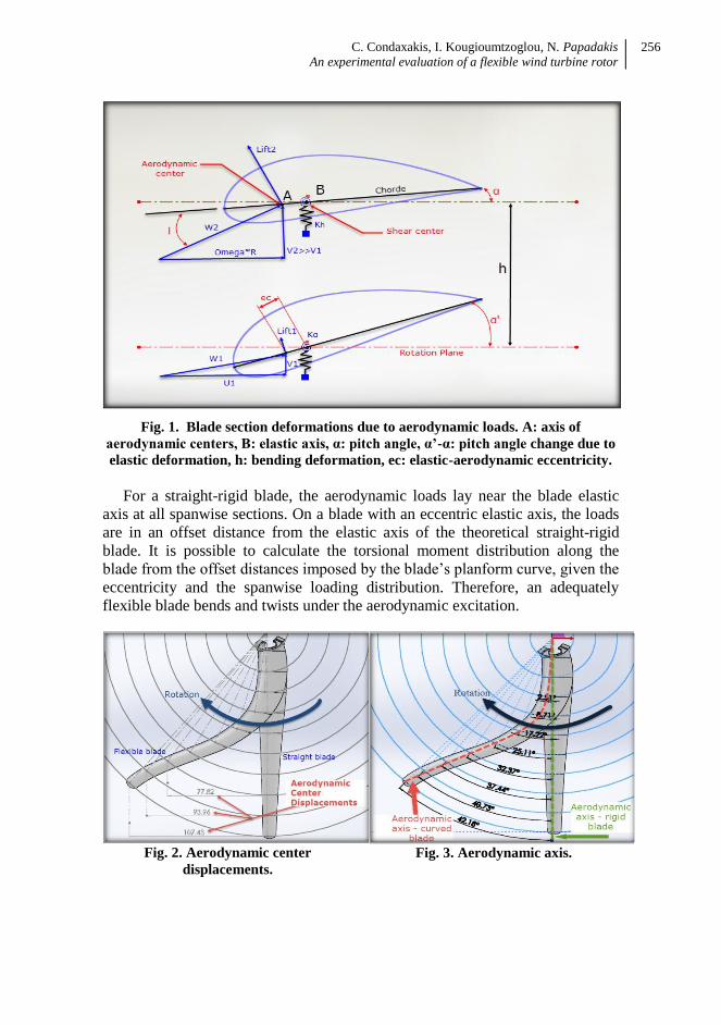
As shown in fig.1, the angle that formed between the resultant wind speed
(W2) and the Chord, the angle of attack (i), is greater than the one in the second
sketch. Furthermore the pitch angle (α‟-α), as shown in the second sketch, is
changing. This happens due to the wind speed (V2) which is much higher than
(V1), which results in producing much higher lift force. All the above lead to the
bending deformation (h) and twisting deformation of the blade (α‟-α). For high
wind speeds, the value of the attack angle (i) becomes higher causing the blade
to enter in the aerodynamic stall area.
In order to calculate the aero-elastic model, a straight-rigid blade was initially
designed by using the geometry calculated by DEOL program composed by 10
airfoil profiles, along the blade. All the geometric parameters i.e. the chord, the
pitch angle and the airfoil type for each of the 10 sections were already known as
they had been prior calculated. Based on the geometry of the straight-rigid, a
curved geometry blade was designed.
C. Condaxakis, I. Kougioumtzoglou, N. Papadakis
An experimental evaluation of a flexible wind turbine rotor
256
Fig. 1. Blade section deformations due to aerodynamic loads. A: axis of
aerodynamic centers, B: elastic axis, α: pitch angle, α’-α: pitch angle change due to
elastic deformation, h: bending deformation, ec: elastic-aerodynamic eccentricity.
For a straight-rigid blade, the aerodynamic loads lay near the blade elastic
axis at all spanwise sections. On a blade with an eccentric elastic axis, the loads
are in an offset distance from the elastic axis of the theoretical straight-rigid
blade. It is possible to calculate the torsional moment distribution along the
blade from the offset distances imposed by the blade‟s planform curve, given the
eccentricity and the spanwise loading distribution. Therefore, an adequately
flexible blade bends and twists under the aerodynamic excitation.
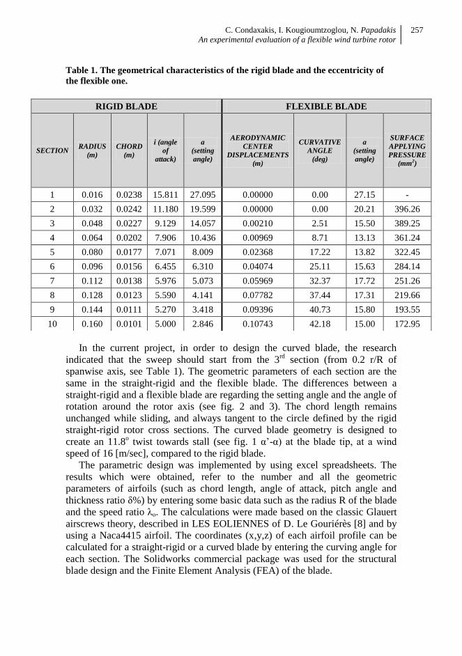
Fig. 2. Aerodynamic center
displacements.
Fig. 3. Aerodynamic axis.
C. Condaxakis, I. Kougioumtzoglou, N. Papadakis
An experimental evaluation of a flexible wind turbine rotor
257
Table 1. The geometrical characteristics of the rigid blade and the eccentricity of
the flexible one.
In the current project, in order to design the curved blade, the research
indicated that the sweep should start from the 3rd
section (from 0.2 r/R of
spanwise axis, see Table 1). The geometric parameters of each section are the
same in the straight-rigid and the flexible blade. The differences between a
straight-rigid and a flexible blade are regarding the setting angle and the angle of
rotation around the rotor axis (see fig. 2 and 3). The chord length remains
unchanged while sliding, and always tangent to the circle defined by the rigid
straight-rigid rotor cross sections. The curved blade geometry is designed to
create an 11.8o twist towards stall (see fig. 1 α‟-α) at the blade tip, at a wind
speed of 16 [m/sec], compared to the rigid blade.
The parametric design was implemented by using excel spreadsheets. The
results which were obtained, refer to the number and all the geometric
parameters of airfoils (such as chord length, angle of attack, pitch angle and
thickness ratio δ%) by entering some basic data such as the radius R of the blade
and the speed ratio λο. The calculations were made based on the classic Glauert
airscrews theory, described in LES EOLIENNES of D. Le Gouriérès [8] and by
using a Naca4415 airfoil. The coordinates (x,y,z) of each airfoil profile can be
calculated for a straight-rigid or a curved blade by entering the curving angle for
each section. The Solidworks commercial package was used for the structural
blade design and the Finite Element Analysis (FEA) of the blade.
RIGID BLADE FLEXIBLE BLADE
SECTION RADIUS
(m)
CHORD
(m)
i (angle
of
attack)
a
(setting
angle)
AERODYNAMIC
CENTER
DISPLACEMENTS
(m)
CURVATIVE
ANGLE
(deg)
a
(setting
angle)
SURFACE
APPLYING
PRESSURE
(mm2)
1 0.016 0.0238 15.811 27.095 0.00000 0.00 27.15 -
2 0.032 0.0242 11.180 19.599 0.00000 0.00 20.21 396.26
3 0.048 0.0227 9.129 14.057 0.00210 2.51 15.50 389.25
4 0.064 0.0202 7.906 10.436 0.00969 8.71 13.13 361.24
5 0.080 0.0177 7.071 8.009 0.02368 17.22 13.82 322.45
6 0.096 0.0156 6.455 6.310 0.04074 25.11 15.63 284.14
7 0.112 0.0138 5.976 5.073 0.05969 32.37 17.72 251.26
8 0.128 0.0123 5.590 4.141 0.07782 37.44 17.31 219.66
9 0.144 0.0111 5.270 3.418 0.09396 40.73 15.80 193.55
10 0.160 0.0101 5.000 2.846 0.10743 42.18 15.00 172.95
C. Condaxakis, I. Kougioumtzoglou, N. Papadakis
An experimental evaluation of a flexible wind turbine rotor
258
III. Construction process
A very important parameter, for the blades, is the construction material. High
Density Polyethylene (HDPE) material was selected because of its mechanical
properties (800 N/mm2 of elastic modulus and 30 N/mm
2 of tensile strength).
The selection of HPDE was validated through Finite Elements Analysis. For the
construction of the blades, a two axis CNC machine was used in order to have a
solid structure. After the construction of the blades, a hub was designed and
constructed in a 3D printer using ABS material and afterwards the rotor was
assembled.
IV. Experimental procedure
Once the rotor was completed, it was tested statically using weights simulating
the aerodynamic loads, in order To measure the deformations regarding the displacement and angle
along the blade and compare them to the corresponding calculated
values.
To ensure the strength of the blade under the loads.
The comparative results are in compliance to the expected behavior for both
the straight and the curved blade.
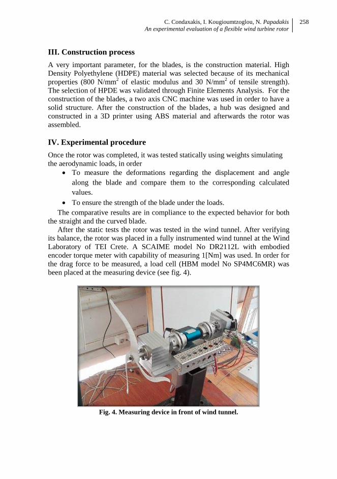
After the static tests the rotor was tested in the wind tunnel. After verifying
its balance, the rotor was placed in a fully instrumented wind tunnel at the Wind
Laboratory of TEI Crete. A SCAIME model No DR2112L with embodied
encoder torque meter with capability of measuring 1[Nm] was used. In order for
the drag force to be measured, a load cell (HBM model No SP4MC6MR) was
been placed at the measuring device (see fig. 4).
Fig. 4. Measuring device in front of wind tunnel.
C. Condaxakis, I. Kougioumtzoglou, N. Papadakis
An experimental evaluation of a flexible wind turbine rotor
259
The rotational speed, torque, and drag force were measured at different wind
speed velocities. The wind speed at the wind tunnel outlet was measured with a
Pitot-Prandtl tube and a Delta Ohm HD408T differential pressure transducer.
The data acquisition system was built upon Labview 8.6 Development System.
V. Measurements Procedure
When the rotor was tested in the wind tunnel, two sets of measurements were
carried out to improve the accuracy of the results. If the measurements were not
relatively identical (difference > 1%) they would be rejected and repeated. The
measurements‟ sampling rate was 100ms.
Four different sets of tests were conducted for both the straight-rigid and the
curved rotor:
The first test was without applying any load to the rotor.
The second test was conducted applying a small load using a constant
mechanical brake to the rotor axis
The third test was conducted applying a bigger load using a constant
mechanical brake to the rotor axis and
The last test was with constant wind speed and variable load.
The torque measurements were accomplished with the use of brake in every
wind speed from 4-19 [m/sec].
VI. Measurement Post-Processing
The data were stored in ASCII format. The analysis was carried out using
Labview and Excel (.xls).
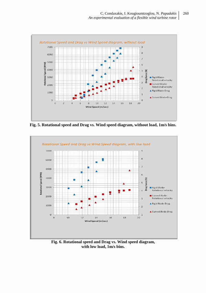
Fig. 5 presents a graph of Rotational speed versus the wind speed velocity.
Three regions can be observed with respect to the wind speed:
- up to 4[m/s]: Rotational velocity is zero for the curved blade and up to
6[m/s] for the straight-rigid blade.
- 4[m/s] - 16[m/s]: The rotational velocity increases almost linearly from
zero up to approximately 2750[rpm] for the curved blade and up to
7000[rpm] for the straight-rigid blade.
- 16[m/s] - 19[m/s]: The rotational velocity reaches a plateau between
2500 and 3000[rpm] for the curved blade. The straight-rigid blade broke
at wind speed 16[m/s] so it was impossible to observe its behavior at this
wind speed range.
- For the Drag measurements a linear continuous increase is observed for
the straight-rigid blade that results in the blade failing, while in the
measurements of the curved blade, an increase much lower (about 30%
of the drag) in comparison to the rigid blade, is observed.
C. Condaxakis, I. Kougioumtzoglou, N. Papadakis
An experimental evaluation of a flexible wind turbine rotor
260
Fig. 5. Rotational speed and Drag vs. Wind speed diagram, without load, 1m/s bins.
Fig. 6. Rotational speed and Drag vs. Wind speed diagram,
with low load, 1m/s bins.
C. Condaxakis, I. Kougioumtzoglou, N. Papadakis
An experimental evaluation of a flexible wind turbine rotor
261
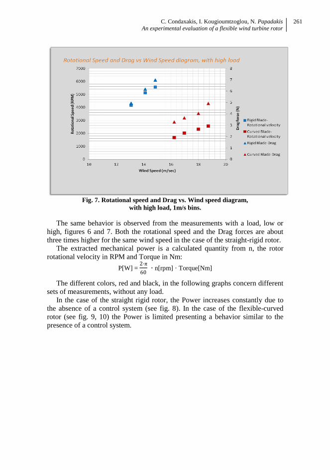
Fig. 7. Rotational speed and Drag vs. Wind speed diagram,
with high load, 1m/s bins.
The same behavior is observed from the measurements with a load, low or
high, figures 6 and 7. Both the rotational speed and the Drag forces are about
three times higher for the same wind speed in the case of the straight-rigid rotor.
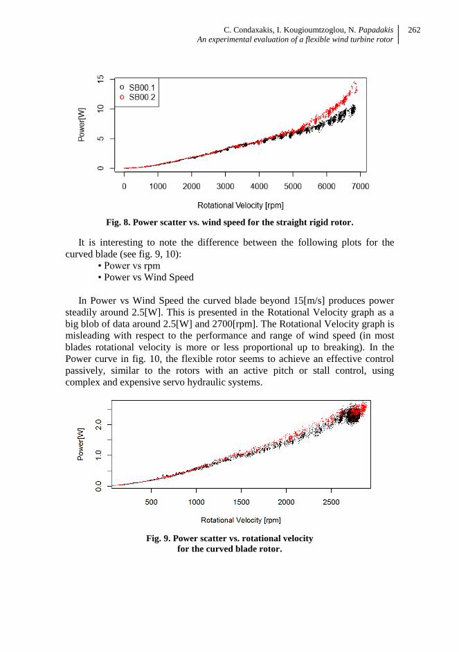
The extracted mechanical power is a calculated quantity from n, the rotor
rotational velocity in RPM and Torque in Nm:
P[W] = 2·π
60 · n[rpm] · Torque[Nm]
The different colors, red and black, in the following graphs concern different
sets of measurements, without any load.
In the case of the straight rigid rotor, the Power increases constantly due to
the absence of a control system (see fig. 8). In the case of the flexible-curved
rotor (see fig. 9, 10) the Power is limited presenting a behavior similar to the
presence of a control system.
C. Condaxakis, I. Kougioumtzoglou, N. Papadakis
An experimental evaluation of a flexible wind turbine rotor
262
Fig. 8. Power scatter vs. wind speed for the straight rigid rotor.
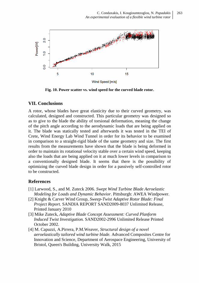
It is interesting to note the difference between the following plots for the
curved blade (see fig. 9, 10):
• Power vs rpm
• Power vs Wind Speed
In Power vs Wind Speed the curved blade beyond 15[m/s] produces power
steadily around 2.5[W]. This is presented in the Rotational Velocity graph as a
big blob of data around 2.5[W] and 2700[rpm]. The Rotational Velocity graph is
misleading with respect to the performance and range of wind speed (in most
blades rotational velocity is more or less proportional up to breaking). In the
Power curve in fig. 10, the flexible rotor seems to achieve an effective control
passively, similar to the rotors with an active pitch or stall control, using
complex and expensive servo hydraulic systems.
Fig. 9. Power scatter vs. rotational velocity
for the curved blade rotor.
C. Condaxakis, I. Kougioumtzoglou, N. Papadakis
An experimental evaluation of a flexible wind turbine rotor
263
Fig. 10. Power scatter vs. wind speed for the curved blade rotor.
VII. Conclusions
A rotor, whose blades have great elasticity due to their curved geometry, was
calculated, designed and constructed. This particular geometry was designed so
as to give to the blade the ability of torsional deformation, meaning the change
of the pitch angle according to the aerodynamic loads that are being applied on
it. The blade was statically tested and afterwards it was tested in the TEI of
Crete, Wind Energy Lab Wind Tunnel in order for its behavior to be examined
in comparison to a straight-rigid blade of the same geometry and size. The first
results from the measurements have shown that the blade is being deformed in
order to maintain its rotational velocity stable over a certain wind speed, keeping
also the loads that are being applied on it at much lower levels in comparison to
a conventionally designed blade. It seems that there is the possibility of
optimizing the curved blade design in order for a passively self-controlled rotor
to be constructed.
References
[1] Larwood, S., and M. Zuteck 2006. Swept Wind Turbine Blade Aeroelastic
Modeling for Loads and Dynamic Behavior. Pittsburgh: AWEA Windpower.
[2] Knight & Carver Wind Group, Sweep-Twist Adaptive Rotor Blade: Final
Project Report. SANDIA REPORT SAND2009-8037 Unlimited Release,
Printed January 2010
[3] Mike Zuteck, Adaptive Blade Concept Assessment: Curved Planform
Induced Twist Investigation. SAND2002-2996 Unlimited Release Printed
October 2002.
[4] M. Capuzzi, A.Pirrera, P.M.Weaver, Structural design of a novel
aeroelastically tailored wind turbine blade. Advanced Composites Centre for
Innovation and Science, Department of Aerospace Engineering, University of
Bristol, Queen's Building, University Walk, 2015

C. Condaxakis, I. Kougioumtzoglou, N. Papadakis
An experimental evaluation of a flexible wind turbine rotor
264
[5] Scott Larwood, C.P. van Dam, Daniel Schow, Design studies of swept wind
turbine blade 2014
[6] Xin Shen, Jin-Ge Chen, Xiao-Cheng Zhu, Peng-Yin Liu, Zhao-Hui Du,
Multi-objective optimization of wind turbine blades using lifting surface
method. Shanghai Jiaotong University 2015.
[7] M.G. Khalafallah, A.M. Ahmed & M.K. Emam (2015): CFD study of some
factors affecting performance of HAWT with swept blades. International Journal
of Sustainable Energy, DOI: 10.1080/14786451.2015.1053394.
[8] Désiré Le Gouriérès, Les Éoliennes Théorie, conception et calcul pratique,
2008, Éditions du Moulin Cadiou, ISBN13 : 978-2-953004-10-6
Acknowledgement
The current project has been supported by the 1st Internal Research Support
Program which was funded by the Specific Account for Research and Funds
(ELKE) TEI of Crete.


![[Us 2006] d517986 Wind Turbine and Rotor Blade of a Wind Turbine](https://img.pdfslide.us/doc/110x75/56d6c0731a28ab30169a6fcb/us-2006-d517986-wind-turbine-and-rotor-blade-of-a-wind-turbine.jpg)