Embed Size (px)
Citation preview

The International Journal of Cement Composites and Lightweight Concrete, Volume 6, Number 1 February 1984
A n e v a l u a t i o n of t es t methods for shear modulus of sandwich cores D. J. O'Connor*
* Mr O'Connor is a chartered civil and structural engineer who was previously employed in structural design with various firms of consult- ing engineers. He is presently a senior lecturer in the School of Civil Engineering at Ulster Polytechnic.
@ Construction Press 1984
0262-5075/84/06110003/$02.00
SYNOPSIS Following a brief summary of available tests for shear modulus of sandwich core materials, the present British and American Standards are examined in detail using an experimentally verified finite element analysis. The accuracy and performance of each test method is compared within the range of stiffnesses normally ex- pected from rigid plastic foam cores. Extrapolation for use with other stiffer cement composite cores such as styropor is considered and the general analysis method is commended as an aid to test design.
KEYWORDS Sandwich construction, shear tests, codes (standards), shear modulus, computer analysis, composite materials, sandwich cores, cellular materials, sandwich struc- tures, stress analysis, composite construction, testing, errors, test methods, stiffness.
INTRODUCTION Recent research at Ulster Polytechnic in association with Concrete (N.I.) Limited included the testing and analysis of sandwich beams with GRC skins and styropor and later rigid plastic foam cores. This type of construction provides a strong yet light structure, and escpecially when a high thermal insulation core is incorporated, is very suitable for use in cladding panels. However tests showed that in many cases, especially with rigid plastic foam cores, flexural deformations were significant in design, and in particular, shear deformations in the core contributed a large proportion to the total deflection under load. The accurate deter- mination of core shear modulus was thus important. Various methods of test were available and certain sources and pilot tests showed considerable difference in shear modulus values found using different test methods. This paper discusses suitable tests for shear modulus and presents a recent study into the accuracy of the current British and American test methods.
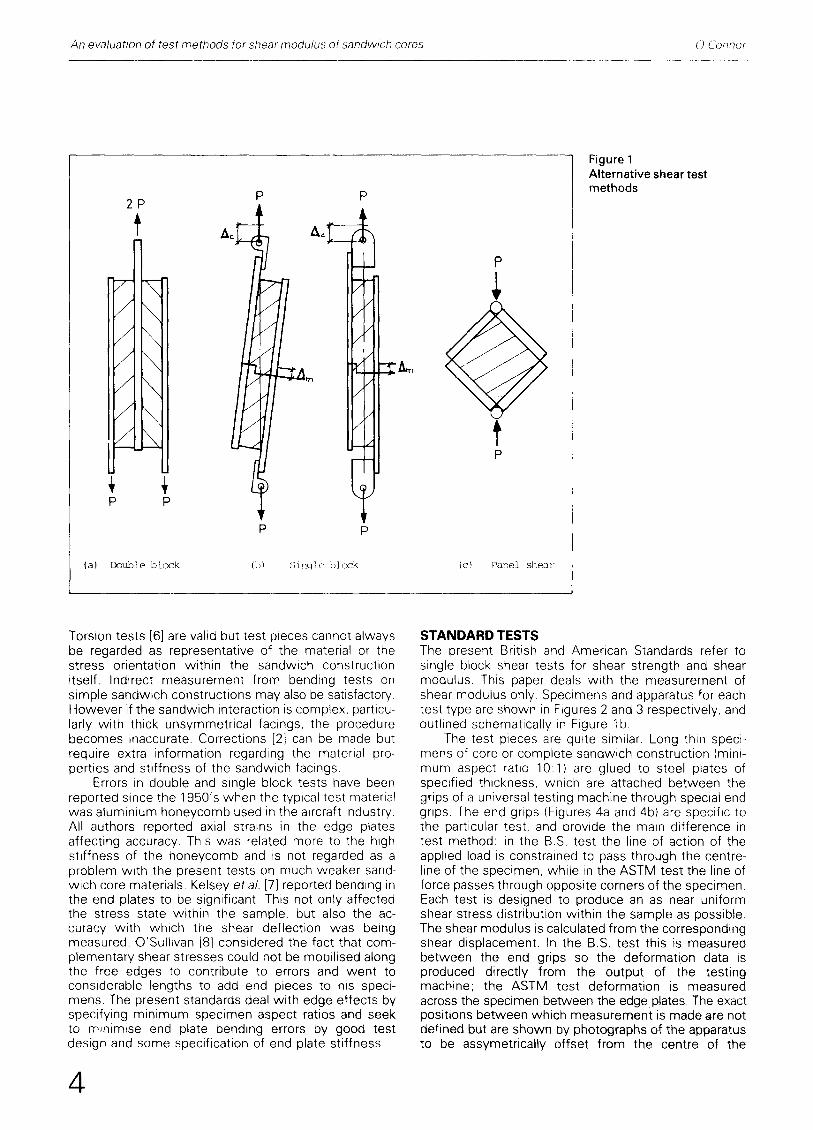
Shear test methods for the cores of sandwich construction are adequately reviewed by Allen [1,2] and the ASTM Symposium [3]. The general methods are outlined in Figure 1. In each case a specimen of sand- wich core or complete sandwich construction is glued to 'heavy metal' edge plates. The test method is designed to apply direct load so as to induce an as- sumed uniform shear stress within the specimen, shear modulus being calculated from the corresponding shear displacement measured. The panel shear test (Figure lc) is considered better for material available in bulk, and is less suitable for thin sandwich layers. The double and single block tests (Figures l a and l b) are equally applicable to sandwich cores or sandwich constructions. The double block test attempts to use symmetry to reduce test errors, but there is obviously more work involved in specimen preparation and indeed the test uses twice as many test samples. The British and American standard single block shear test methods [4, 5] are the simplest and most applicable test methods, and these are investigated further in this paper.
Other less direct methods may also be used.
3
An evaluation of test methods for shear modu/us of sandwich cores O'C'om~or
2 P
S k NR S t
P P
P
P p
(a) Double b l o c k (b) S i n q l e b l o c k
e3
P
t P
(c} Pane] shea;-
Figure 1 Alternative shear test methods
Torsion tests [6] are valid but test pieces cannot always be regarded as representative of the material or the stress orientation within the sandwich construction itself. Indirect measurement from bending tests on simple sandwich constructions may also be satisfactory. However if the sandwich interaction is complex, particu- larly with thick unsymmetrical facings, the procedure becomes inaccurate. Corrections [2] can be made but require extra information regarding the material pro- perties and stiffness of the sandwich facings.
Errors in double and single block tests have been reported since the 1950's when the typical test material was aluminium honeycomb used in the aircraft industry. All authors reported axial strains in the edge plates affecting accuracy. This was related more to the high stiffness of the honeycomb and is not regarded as a problem with the present tests on much weaker sand- wich core materials. Kelsey etal. [7] reported bending in the end plates to be significant. This not only affected the stress state within the sample, but also the ac- curacy with which the shear deflection was being measured. O'Sullivan [8] considered the fact that com- plementary shear stresses could not be mobilised along the free edges to contribute to errors and went to considerable lengths to add end pieces to his speci- mens. The present standards deal with edge effects by specifying minimum specimen aspect ratios and seek to minimise end plate bending errors by good test design and some specification of end plate stiffness.
STANDARD TESTS The present British and American Standards refer to single block shear tests for shear strength and shear modulus. This paper deals with the measurement of shear modulus only. Specimens and apparatus for each test type are shown in Figures 2 and 3 respectively, and outlined schematically in Figure lb.
The test pieces are quite similar. Long thin speci- mens of core or complete sandwich construction (mini- mum aspect ratio 10:1) are glued to steel plates of specified thickness, which are attached between the grips of a universal testing machine through special end grips. The end grips (Figures 4a and 4b) are specific to the particular test, and provide the main difference in test method: in the B.S. test the line of action of the applied load is constrained to pass through the centre- line of the specimen, while in the ASTM test the line of force passes through opposite corners of the specimen. Each test is designed to produce an as near uniform shear stress distribution within the sample as possible. The shear modulus is calculated from the corresponding shear displacement. In the B.S. test this is measured between the end grips so the deformation data is produced directly from the output of the testing machine; the ASTM test deformation is measured across the specimen between the edge plates. The exact positions between which measurement is made are not defined but are shown by photographs of the apparatus to be assymetrically offset from the centre of the
4

An evaluation of test methods for shear modulus of sandwich cores O'Connor
Figure 2 British Standard shear test Figure 3 American Standard shear test
I i
Figure 4 Standard end grip details showing computer idealisation. (a) American test; (b) British test
5

An evaluation of test methods for shear modulus of sandwich cores O'Connor
X X X 2X 2X 3X 4X 6]( 1
X l l l l
.11
': III
) '
LU
L E N G T H
r t, O 0 0 - - - -
Figure 5 a Computer model of shear test specimen - half section b Typical shear stress contour plot mapped onto finite element mesh
specimen approximately at quarter points. A compari- son of test specifications is given below.
The American Standard Test [4] 1. The test is applicable to complete sandwich con-
structions or cores and no restriction is placed on type of material to be tested.
2. The specimen must have a length not less than 12 times its thickness and a breadth not less than twice its thickness.
3. The thickness of the steel plates may be varied with the strength of the sandwich. Load plates wi th a stiffness greater than 2.67 MN,cm 2 per cm of width per cm of core thickness are recommended.
4. Deformation is measured across the specimen be- tween the edge plates.
The British Standard Test [S] 1. The test relates to cores only and those formed
from rigid cellular materials (e.g. rigid plastic foams). 2, The test specimen dimensions are specified as
250 mm x 50 m m x 25 mm thick cut from the core of the sandwich.
3. Steel plates not less than 5 mm thick are specified. 4. Deformation is measured between the end grips of
the testing machine.
TEST PROGRAMMES Both test methods were examined using an experi- mentally verified computer analysis. Two programmes were progressed in parallel. A finite element computer model of each test sequence was formulated which was then used to examine in detail the effect of varying a range of test parameters on the errors produced in
shear displacement measurement. The computer results form the basis for the test comparisons. In addition a laboratory programme was instigated to pro- vide deformation data on a range of test specimens which were used to verify the computer model. The comparison was initially based on the range of stiff- nesses normally expected from rigid polyurethane foam cores, that is shear modulii between 0.6-5.0 N/mm 2 The confirmed computer model and the general recom- mendations of this paper are however applicable to other material stiffnesses.
COMPUTER ANALYSIS The finite element computer model utilised a plane elasticity element RT169 for the core specimen. This is an eight-noded rectangular element which exhibits a quasi-parabolic response; direct strains being linear in the direction of strain and quadratic transversely, while shear strains are completely quadratic. An extensive convergence study showed the element to be quite efficient. The final mesh is shown in Figure 5a; elements are concentrated at areas of high strain gradient near the boundaries and widened out towards the centre of the specimen. The associated shear stress contour plot shown in Figure 5b shows the final mesh to be well related to stress gradient.
The steel end plates utilised the six D.O.F. BME69 element. This is based on the normal 'engineers' beam element, but the element stiffness matrix was altered to allow the additional facility for nodes to be specified at an eccentricity to the beam centreline. This allowed the edge plate 'beams' to be attached eccentrically to the core nodes and also was most useful in the modelling of the special test end grips as shown in Figure 4.
6

An evaluation of test methods for shear modulus of sandwich cores O'Connor
Laboratory programme A selected range of test con- figurations were used to validate the computer model, and at the same time compare the two test methods. As the apparatus and test designs themselves were under scrutiny rather than the specimen, it was import- ant to find a test material which was sensibly homo- geneous and isotropic and also behave in a linearly elastic manner. Polyurethane elastomer, a material formed by the cold curing of two liquid components, was found to be very satisfactory in this respect. In particular load-deformation curves were very straight, which allowed a singular value of modulus to be obtained.
The British standard specimen size of 250 mm x 50 mm x 25 mm was adopted for all tests: having an aspect ratio of 10:1 this was acceptably close to the minimum specified ASTM value of 12:1. The advantage of the single specimen was that the same material could be tested in both test modes, simply by exchang- ing the special end grips associated with each test method.
By the same reasoning both the crosshead displace- ment (Ac) and the cross-plate displacement (Am) were measured during each test. In effect Ac was output directly from the testing machine load-deformation graph while the ratio Ao/Am was provided from two displacement transducers connected to the crosshead and cross-plate respectively, and recorded as a gradient
A
f.q
H
2C
IO
O 2. z
Figure 6
8 ASPECT RATIO
IC)
Computer model: errors in pure shear stress sample with free ends
12
on an X-Y plotter. As the exact position of the cross- plate displacement was ill defined in the American standard, special mountings as shown in Figure 3, were designed to allow this measurement to be recorded at the centreline of the specimen. It was considered that this revision would further decrease errors due to plate bending.
The British standard allows 5 mm thick steel end plates whereas the American Standard recommenda- tions equate to 15 mm plates. A range of plate sizes (3.2, 5.0, 12.5, 15.0) was used in conjunction with elastomer specimens of two different stiffnesses (shear modulus G = 0.6 and 1.6 N/mm 2 approx.) The 3.2 mm plates were used to amplify the displacement errors for computer model verification.
DISCUSSION OF RESULTS
Computer analysis The computer model was used to examine the behaviour of both test types under a range of test configurations. The results are presented in terms of errors in displacement measurement, which represent the difference between the predicted test displacements and the theoretical displacement assum- ing a uniform shear stress throughout the specimen.
Displacement error may be defined by:
A % - - { A F E - - A ° ) X 100 Ao
where A% -- percentage error in displacement measurement
AFE = displacement result output from finite element model computer test
Ao = theoretical shear displacement calculated using linear stress/strain re- sponse assuming a uniform shear stress distribution throughout the specimen.
End effects A pure shear force was applied to the specimen through stiff edge plates which were con- strained to move parallel to each other without bending or rotation; the ends of the specimen were however left free. Figure 6 shows the variation in displacement error with specimen aspect ratio for this singular case when no complementary shear stresses are mobilised at the ends. There is as expected, a significant increase in error at low aspect ratios, decreasing markedly as aspect ratios increase. In particular there is only a slight difference between aspect ratios of 10:1 and 12: 1.
Edge plates Figure 7 shows results relating to the British Standard. The American Standard response is of similar form. Errors are plotted against plate thickness at different material moduli (G). Both crosshead and cross-plate errors are magnified at the lower thicknesses and converge to a single value as thickness increases. This value is in fact the pure shear result detailed earlier. Errors are also dependent on stiffness of specimen, both displacement errors being magnified with in- creased stiffness. The results are shown in a different
B 7

An evaluabon of test methods for shear modulus of sandwich cores I:) 'Connor
oo
c<
u] c~
4.0
~ 0
2O
I 0
0
- I O L_ 0 5 IO
C "d:s shead
ossl)! ate D i :;~ ~|. a c e P c ' p L
Dlsp].acemen t
2
Figure 7 Computer model: British Standard test errors
~, 2 o
P L A T E q ? H I C K ] ' E S S ( iT~J
4 0
8

An evaluation of test methods for shear modulus of sandwich cores O'Connor
format in Figure 8a, and here it can be seen that the relationship with stiffness is almost linear. Figure 8b shows similar results for the American Standard as a
comparison. It can be seen that for both test types crosshead errors are far in excess of the equivalent cross-plate effects, both converging towards the pure
a 80
50
"z
z, 20
10
+4-0
Z
+2-0
r~
E
I u3
2 0-0
- 1.0
Figure 8
/ /
0 0'0
% /
/ - -
T=40
1.0 2.0 3.0 Si{tg',R .ME)DUT~S (N/rm~ 2 )
4,0
J /
,15
5'0
b
\
T - 4 0
15-0
r ~
/ /
, / /
© 0"0
v
c~
u3
,"u I cQ
,L.)
J J
-_~__&~o j I
1.0 2.0 3.0 SHF~,_R Nk3Dr j ] . ,US ( N / , q ~ 2 )
5.o ~ - ' - ' ~ ~ \
~cb
I oO
Computer mode l : Compar ison of Brit ish and Amer ican Standard test errors (a) Brit ish Standard (b) Amer ican Standard
4.0 5-0
"T - 4 0
9

An evaluation of test methods for shear modulus of sandwich cores O'Cor~nor
shear value with increased plate thickness. In addition the British Standard error results are much higher than their equivalent American Standard Values.
General Distortion in the shear stress distribution is caused by the free end effects together with variations caused by plate bending. Figure 5b shows a contour mapping of a typical shear stress distribution within a test specimen. The close contour grouping near the edge of the specimen shows that end effects are dissipated within a specimen depth longitudinally, the centre of the specimen having a near uniform stress distribution (bounded by contour 1.000). Plate bending effects cause lack of symmetry in the stress patterns and are most evident in the same areas, the British test giving more distortion than the American.
The end distortions are controlled mainly by the
stiffness in the transverse direction. For any value of shear modulus the elastic modulus is controlled by Poisson's ratio. Thus, in the computer model, there is a variation in displacement error with Poisson's ratio and indeed whether plane stress or plane strain is specified
Styreper A short pilot study modelling 100 mm thick cores or sandwiches with much higher stiffnesses of the order of 250 N/mm 2 and more appropriate to materials such as Styropor showed that the American test performed appropriately well. Crosshead displace ments in a British Standard type test were grossly magnified. The required plate thickness was however 25 mm. Further models indicated that a double block type test incorporating a single specimen would give accurate results using less thick edge plates.
Table 1 Comparison of laboratory results with computer model for weak elastomer specimen
Shear modulus (N/mm 2)
Experimental Computer Test results corrected
% errors in displacement measurement Computer analysis Experiment
Am Ac AU'Am A~:/A,~,
B.S. 3.2 0.40 0.56 -1.4 39.3 41.3 49.0 0.60 0.59 0.59 0.60
ASTM3.2 0.53 0.56 1.5 7.9 6.3 12.0
B.S. 5.0 0.55 0.64 1.4 15.8 14.3 15.8 0 . ~ 0.65 0 . ~ 0.65
ASTM5.0 0.59 0.62 1.9 4.6 2.6 7.0
B.S~2.5 0.57 0.59 2.6 4.3 1.6 5.0 0.60 0 . ~ 0.58 0.60
ASTM12.5 0.56 0.58 2.2 2.5 0.2 3.0
Table 2 Comparison of laboratory results with computer model for stiff elastomer specimen
Shear modulus (N/mm 2)
Experimental Computer Test results corrected
B.S. 3.2 0.84 1.60 1.60 7.48 1.51 1.51
ASTM 3.2 1.26 1.36
B.S. 5.0 1.17 1.53 1.66 1.65 1.62 1.64
ASTM 5.0 1.42 1.50
B.S. 15.0 1.42 1.49 1.51 1.54 1.51 1.54
ASTM15.0 1.41 1.46
% errors in displacement measurement Computer analysis Experiment
At,, '&c 'AUAm 'Ac/A.,
-7.0 899 104.0 90.0
0.3 7.5 7.2 19.0
-0.4 31.0 32.0 42.0
1.5 5.7 4.0 14.0
2.5 5.2 2.6 6.0
2.2 3.6 1.5 7.0
10

An evaluation of test methods for shear modulus of sandwich cores O'Connor
Laboratory verification A comparison between labora- tory results for specimens of two different stiffnesses and the computer analysis is shown in Tables 1 and 2. The crosshead/cross-plate displacement ratio (Ac/Am) was used as one means of error measurement. The experimental value was output directly as a graph plot during each test sequence and the computed value easily calculated from associated computer analysis.
In addition, shear modulus values for each test are tabulated. The figures in bold type are associated with the crosshead displacement obtained directly from the testing machine output. The values in italics relate to the cross-plate displacement and are computed from the former moduli values factored by the laboratory measured Ac/Am ratio. Experimental values for each test type and both methods of displacement measurement may be compared. In addition the computer corrected values also tabulated give an indication of the efficiency of the computer model.
Errors It should be noted that the values quoted in the tables are percentage errors rather than actual values, which makes the comparisons between laboratory results and computer predictions favourably close, tn general there is a constant error between computed and experimental displacement ratios. Further tests have shown that this is a crosshead displacement error caused by additional flexibility in the apparatus. A further discrepancy may be noted in British Standard tests using the lower plate thicknesses. This may be ac- counted for by the fact that the computer model cannot respond to the secondary effects of large displace- ments. The result is that the extremes of displacement are overestimated in the computer analysis. Although this is a limitation of the program, it does not affect the conclusion of this study.
A comparison of the modulus values highlights the errors produced from the crosshead displacement. On the other hand the consistency of cross-plate measure- ment results is apparent, there being little difference in moduli values of a single specimen tested by both methods. The rather small computer corrections aid this comparison, but are of more benefit to the poor cross- head results. The accuracy of computer corrections is even more apparent when the experimental errors previously detailed are accounted for.
Error mechanisms The errors in the single block tests are due to both end effects and plate bending. The singular effect of free ends to the specimen can, however, be limited to a very small value (3-4%) when large aspect ratios are used. When examining plate bending it is convenient to separate effects in the proximity of the specimen from the 'lever arm' effect of the end grip rotations. These extensions are the major source of error in the crosshead measurements and with the British test in particular, rotation in the end grips block causes large diptacements.
The remaining sources of error become evident when the test forces are transferred on to the corners of the specimen as shown in Figures 9a and 9b. Overall
M
p -_
M
(a) Biitish Test
D
P=
Figure 9
(b) American Test
Comparison of test forces on specimens
equilibrium is of course maintained in each case, but in the American test the forces are better balanced about the specimen, the pure shear force Pc being balanced by the opposite couple due to Ps. There is a small initial moment at each plate edge due to the force Pc acting at half the thickness which is dissipated to zero at the other end. With the British specimen, however, the counter balance moment is applied directly through the end plate at the specimen corner, and has a large effect on plate distortion. The rotation created further amplifies the lever arm effects discussed previously, and also distorts the stess distribution within the sample, particu- larly at the free corner where a tendency to 'peel' may be promoted.
CONCLUSIONS The computer model has been sensibly verified by the associated laboratory programme and has been suc- cessfully used to predict the response of both the American and British Standard single block shear tests for shear modulus over the range of shear stiffnesses normally associated with rigid plastic foams. A short pilot study has shown the analysis to be valid for much stiffer core materials normally formed from cement composites, and as such could be a valuable tool in future test design.
The main conclusions from the British and American test comparison study are as follows:
1, The errors in crosshead displacement measurement are much larger than the associated cross-plate measure- ments, the error becoming excessive as the edge plate thickness is reduced. Both errors are also magnified by increase in specimen stiffness. Both errors diverge about a single positive value (3-4%) equal to the pure shear free end value, the crosshead value above and the cross-plate value below tending towards zero. This has the further effect of increasing the real value of the crosshead error.
2. The predicted errors of tests carried out under the
11

An evaluation of test methods for shear modulus of sandwich cores ©'(/onnc~r
current British Standard Specification are large. The specification of crosshead displacement measurement and the use of small edge plates (5 mm) are the main contributing factors; but there are also indications that the method of applying the loading to the specimen causes extra stress concentrations at the corners.
3, The ASTM test as specified leads to only minor errors in displacement measurement. Further calculations have shown that the particular method of measuring cross-plate displacements detailed in the standard does not cause a significant error:provided the recommenda- tions for plate stiffness are observed. These recom- mendations also seem to be appropriate to limit other plate bending effects, although the computer results indicate that some reference to material stiffness would be more technically correct.
ACKNOWLEDGEMENTS The assistance of Mr H. Smith in all the laboratory work is much appreciated.
The author wishes to thank Mr Peter Allen of B + T Polymers Stockport, Cheshire, who advised on and arranged for the supply of the polyurethane elastomer used in the test comparisons.
REFERENCES 1. Allen, H. G. 'Analysis and design of structural sand-
wich panels', Pergamon Press, London, 1969, pp. 254-263.
2. Allen, H. G. 'Measurement of shear stiffness of
sandwich beams', Transactions and Journal of the Plastics Institute, Vol. 35, No. 115, February 1967, pp. 359-363.
3. Clapper, R. B. 'Shear and torsion testing of solid materials - a critical discussion', Symposium on Shear and Torsion Testing, ASTM STP 289, Ameri- can Society for Testing and Materials, 1960, pp. 111-120.
4. American Society for Testing and Materials 'Shear test in flatwise plane of flat sandwich construction or sandwich cores', ASTM C273, 1961 (re-approved 1980), American Society for Testing and Materials, Philadelphia, 1961.
5. British Standards Institution 'British Standard Methods of Test for Rigid Cellular Materials', BS4370, Part 2, 1973, British Standards Institution, London, 1973.
6. Parton, G. M. and Shendy, M. E. 'Polystyrene bead concrete properties and mix design', The Interna- tional Journal of Cement Composites and Light- weight Concrete, Vol. 4, No. 3, August 1982, pp. 153-161
7 Kelsey, S., Gellatly, R. A. and Clark, B W. 'The shear modulus of foil honeycomb cores', Aircraft Engineer- ing, Vol. 30, No. 10, October 1958, pp. 294--302.
8. O'Sullivan, H P. 'Double block shear test for foil honeycomb core', Aircraft Engineering, Vol 33, No 3, March 1961, pp. 64-66.
9. O'Connor, D. J 'FEMFESS: A finite element package for plane elasticity problems', Ulster Poly technic Computer Services Department, CSM No. 20/4, September 1981.
12