Embed Size (px)
Citation preview
An Evaluation of Sensing Platforms Usedfor Sensor Network Research
Daniel T. Fokum, Dr. Victor S. Frost,and Dr. Gary J. Minden
ITTC-FY2008-TR-41420-04
December 2007
Copyright © 2007:The University of Kansas2335 Irving Hill Road, Lawrence, KS 66045-7612All rights reserved.
Project Sponsor:Oak Ridge National Laboratory
Technical Report
The University of Kansas
Abstract Multiple communications, networking, and computer platforms are available for
sensor network applications, ranging from motes to complex sensor nodes; which include fully configured computers. Several of these platforms were evaluated for use in a SensorNet architecture with multiple owners. A unique feature of this endeavor is that it goes beyond basic data collection to study the methods of controlling access to sensor network assets. Here, we present the capabilities, strengths and weaknesses of each of the sensing platforms that were evaluated for our effort. The paper concludes by presenting the modifications that were needed to get the platforms to operate in a unified SensorNet architecture, as well as the lessons that were learned from our evaluation.
i
Table of Contents Abstract ................................................................................................................................ i Table of Contents................................................................................................................ ii List of Figures .................................................................................................................... iii List of Tables ..................................................................................................................... iii 1 Introduction...................................................................................................................... 1 2 Previous Work ................................................................................................................. 2 3 Evaluation of Sensor Platforms ....................................................................................... 3
3.1 Specific Functional Considerations and Platform Integration ................................ 3 3.2 Radio Frequency Identification (RFID) Tags ......................................................... 6
3.2.1 Motes................................................................................................................. 8 3.2.2 Gumstix and Robostix..................................................................................... 10 3.2.3 Sun SPOTs ...................................................................................................... 12 3.2.4 Personal Digital Assistants ............................................................................. 14 3.2.5 SensorNet Nodes............................................................................................. 15 3.2.6 Cost versus Capability .................................................................................... 18
4 Conclusions.................................................................................................................... 19 5 References...................................................................................................................... 20 6 Appendices..................................................................................................................... 22
A. Gumstix versus iMotes ......................................................................................... 22 A.1 Features .............................................................................................................. 22
B. Enabling Java Support on the Gumstix................................................................. 23 B.1 Option One ......................................................................................................... 23 B.2 Option Two ........................................................................................................ 24
C. Other Technologies............................................................................................... 25
ii

List of Figures Figure 1: Sensor Platform Integration................................................................................. 5 Figure 2: RFID Tags ........................................................................................................... 7 Figure 3: Assembly of MICA2 mote with Cyranose 320 sensor........................................ 9 Figure 4: Gumstix, Robostix and Sensor Assembly ......................................................... 11 Figure 5: Base station and Free-Range Sun SPOTs.......................................................... 13 Figure 6: HP iPaq 6945..................................................................................................... 15 Figure 7: SensorNet node composition, from [2] ............................................................. 16 Figure 8: Cost/ Capability Trade-off for Sensor Platforms .............................................. 19
List of Tables Table 1: Summary of IntelleFlex Tag capabilities.............................................................. 6 Table 2: Summary of Savi SensorTag capabilities ............................................................. 7 Table 3: Summary of Mote Capabilities............................................................................. 8 Table 4: Summary of gumstix capabilities ....................................................................... 11 Table 5: Summary of Sun SPOT capabilities ................................................................... 13 Table 6: Summary of HP iPaq 6945 capabilities .............................................................. 15 Table 7: Summary of SensorNet node capabilities, [31], [32] ......................................... 17 Table 8: Summary of features and capabilities of a 2007 workstation model.................. 18 Table 9: Comparison of the Gumstix XM line and the iMote .......................................... 23 Table 10: Summary of IEEE P1902.1 capabilities and features....................................... 26 Table 11: Summary of IEEE 802.11p capabilities and features ....................................... 26
iii
1 Introduction Sensor networks are an emerging application of advanced wireless networking and
computer technology. Sensor networks typically consist of a set of small resource-constrained computers, called sensor nodes that collect data from their environments and then transmit that data on to a base station, or other central site. In general a wireless sensor node (WSN) would consist of a sensing device, e.g., an electronic nose, a temperature sensor or a motion detector, a small microprocessor, a radio and a limited energy source. It should be noted that when a sensor node is connected to just one sensor, the sensor node is sometimes called a sensor, which causes some confusion [1]. Base stations, unlike wireless sensor nodes, will generally have radios, but will have available more computing resources and a larger energy source. The base stations will generally aggregate information from the nodes and then pass them on to other computers for presentation [1]. In a bid to avoid confusion, this paper will use the term “sensor platform” to refer to a device that consists of a microprocessor, memory for storing sensor data, input ports for sensors, a radio and a limited energy source. Sensor platforms will generally not be required to have integrated sensors.
SensorNet nodes are an important component of the SensorNet effort – an effort coordinated by Oak Ridge National Laboratory that aims to develop a nationwide network of chemical, biological, radiological, nuclear and explosive (CBRNE) sensors. The information from these sensors will then be made available to a variety of users [2]. SensorNet nodes differ from the wireless sensor nodes discussed above in that they are not limited to having a small microprocessor, radio, and a limited energy source. Instead, as we shall see, these SensorNet nodes possess processors with hard disks, as well as wireless and wireline communication links.
The overall objectives of this SensorNet research effort are to develop a sensor network that extends beyond basic data collection to incorporate multiple users who have different roles within the sensor network. As a result, this SensorNet must provide the following capabilities [3]: • Assured and controlled access to SensorNet assets. • Open standards to archive and disseminate information. • An application layer that can support high-bandwidth applications such as video
and image transfer. This effort is different from other research on sensor networks in that it attempts to
address the concept of multiple owners in the context of a sensor network. The contributions of this paper include the following: (1) we present a list of sensor
platforms that were evaluated along with the capabilities, strengths and weaknesses of each platform. (2) We show applications of each platform in sensor networking research, as well as provide listings of some communities that support deployments of a given platform. This review is intended to help others in their selection of platforms for future SensorNet implementations. The rest of this paper is laid out as follows; in the next section we provide a review of the Sensor Node architecture as defined in [2]. Section 3 provides an overview of the sensor platforms that have been evaluated during the course of the project. This section also lists other applications of each platform in sensor networking efforts. Finally, we provide some concluding remarks in section 4.
1
2 Previous Work The last section provided an introduction to sensor networks and the definition of a
sensor platform. In this section we provide a review of the objectives of the SensorNet effort [2], and previous sensor network research. This section also gives an overview of the Ambient Computing Environment (ACE), a component of the SensorNet architecture to support multiple owners.
The objective of SensorNet is to make information from a dispersed set of sensors available to many users. According to [2], the SensorNet is defined as "a net-centric information infrastructure for the real-time detection, identification, and assessment of chemical, biological, radiological, and nuclear threats." Once data is collected, the SensorNet would aim to provide a secure and reliable environment for timely delivery of sensor data. The SensorNet is based on open standards enabling many choices for equipment while allowing for the extensibility and maintainability of the system. Some examples of open standards that are used in SensorNet include the IEEE 1451 standard – for communication between sensors and SensorNet nodes, – and the use of XML messages to forward data from SensorNet nodes to SensorNet databases [2]. The latter is done so that new sensors can be added to the database without the need for changing the database structure. In another example of the use of open standards, the SensorNet architecture is based on a data-centric model instead of an application-centric model, so that users can access data using Web services. This data may be provided either by on-demand queries, or via alerts that are triggered on sensors.
The basic building block of the SensorNet architecture is a SensorNet node, which is discussed in greater detail in section 3.4. SensorNet nodes are autonomous platforms that may be either mobile or fixed – for example they may reside at a base station on the cellular telephone network, – and they will be responsible for executing the programs that are necessary to run all the attached sensors. In addition these nodes will be responsible for forwarding sensor data to either regional or national data centers. The SensorNet nodes will make data available to users either on demand, via periodic uploads, or when an “interesting” event occurs. Users may be provided access to SensorNet nodes by a proxy node. Once this access is granted, users may then be granted access to sensor data either periodically or whenever needed by the user. In addition, the users will also be granted access to services to trigger a sensor [2].
Another building block of our architecture is the Ambient Computing Environment (ACE). The ACE framework is used in the SensorNet architecture to provide authorization, authentication and accounting (AAA) functionality that controls connections between applications and sensor nodes; providing a framework for enabling multiple owners. Consequently ACE’s security model is reviewed in the following paragraphs. ACE uses transport layer security (TLS) for authorization [4], TLS and AES (Advanced Encryption Standard) for data encryption, and Keynote Trust Management [4] for distributing permissions to clients.
When a user needs to use a given service, the user contacts the server to create a session key using TLS. Once the session key has been created all the datagrams are encrypted using the session key. These session keys are generated by a random number generator. The session key is changed after a certain interval to prevent too much data from being encrypted with one key. Datagrams are protected with a packet key under ACE. The general packet format includes a packet key, a packet initialization vector, as
2
well as a SHA-1 hash of the packet's payload. The packet's payload is subsequently encrypted with the AES algorithm using a 128 bit key. It is worth noting that each packet's data is encrypted with a different packet key, while the packet key and the packet initialization vector are protected with the session key. It should be observed that the SHA-1 hash of the packet's payload does not provide any security since it occurs outside of the encrypted payload. ACE uses other mechanisms for managing users’ access to services but these mechanisms are outside the scope of this paper. The reader is referred to [4] for additional details. In the next section we will discuss different platforms that were evaluated for use in SensorNet for either collecting or displaying data.
3 Evaluation of Sensor Platforms In the last section, we provided an outline of the goals of the SensorNet
architecture, as well as some of the requirements for a SensorNet node. In this section we discuss the sensor platforms that were evaluated for use in the SensorNet, the strengths and weaknesses of each platform, as well as the alignment of each platform with the project goals.
In accordance with Moore’s Law the functionality of computing devices has been increasing, while the cost of these devices has decreased. The decrease in cost opens up the way for computing devices to play new roles including remote sensing and embedded two-way communications. On the other hand, the increase in computing features means that there is a wide range of devices available for sensor networks ranging in size and functionality from motes to SensorNet nodes.
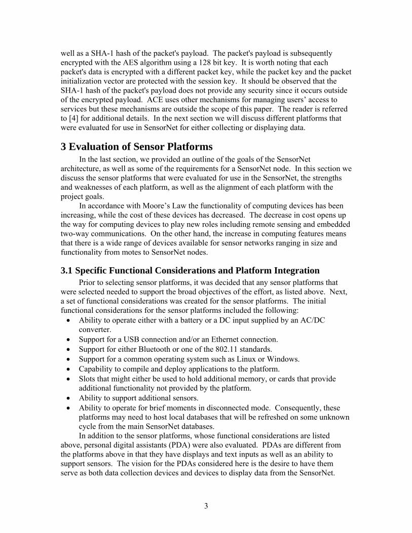
3.1 Specific Functional Considerations and Platform Integration Prior to selecting sensor platforms, it was decided that any sensor platforms that
were selected needed to support the broad objectives of the effort, as listed above. Next, a set of functional considerations was created for the sensor platforms. The initial functional considerations for the sensor platforms included the following: • Ability to operate either with a battery or a DC input supplied by an AC/DC
converter. • Support for a USB connection and/or an Ethernet connection. • Support for either Bluetooth or one of the 802.11 standards. • Support for a common operating system such as Linux or Windows. • Capability to compile and deploy applications to the platform. • Slots that might either be used to hold additional memory, or cards that provide
additional functionality not provided by the platform. • Ability to support additional sensors. • Ability to operate for brief moments in disconnected mode. Consequently, these
platforms may need to host local databases that will be refreshed on some unknown cycle from the main SensorNet databases. In addition to the sensor platforms, whose functional considerations are listed
above, personal digital assistants (PDA) were also evaluated. PDAs are different from the platforms above in that they have displays and text inputs as well as an ability to support sensors. The vision for the PDAs considered here is the desire to have them serve as both data collection devices and devices to display data from the SensorNet.
3
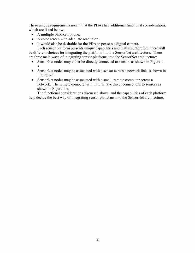
These unique requirements meant that the PDAs had additional functional considerations, which are listed below: • A multiple band cell phone. • A color screen with adequate resolution. • It would also be desirable for the PDA to possess a digital camera.
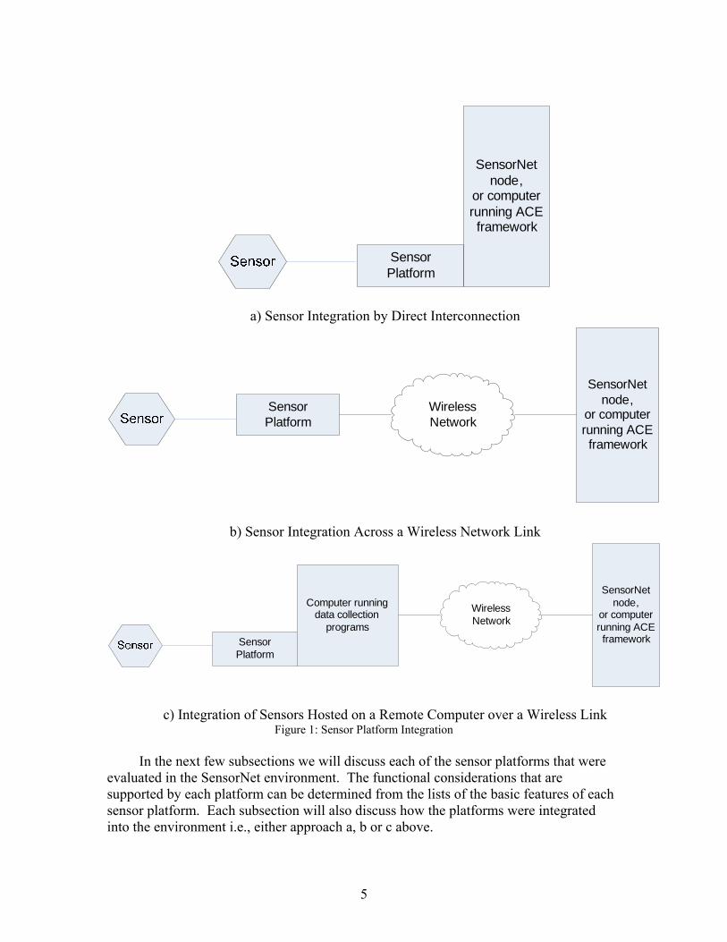
Each sensor platform presents unique capabilities and features; therefore, there will be different choices for integrating the platform into the SensorNet architecture. There are three main ways of integrating sensor platforms into the SensorNet architecture: • SensorNet nodes may either be directly connected to sensors as shown in Figure 1-
a. • SensorNet nodes may be associated with a sensor across a network link as shown in
Figure 1-b. • SensorNet nodes may be associated with a small, remote computer across a
network. The remote computer will in turn have direct connections to sensors as shown in Figure 1-c. The functional considerations discussed above, and the capabilities of each platform
help decide the best way of integrating sensor platforms into the SensorNet architecture.
4
SensorPlatform
SensorNet node,
or computer running ACE framework
a) Sensor Integration by Direct Interconnection
SensorPlatform
Wireless Network
SensorNet node,
or computer running ACE framework
b) Sensor Integration Across a Wireless Network Link
SensorPlatform
Computer running data collection
programs
WirelessNetwork
SensorNet node,
or computer running ACE framework
c) Integration of Sensors Hosted on a Remote Computer over a Wireless Link Figure 1: Sensor Platform Integration
In the next few subsections we will discuss each of the sensor platforms that were
evaluated in the SensorNet environment. The functional considerations that are supported by each platform can be determined from the lists of the basic features of each sensor platform. Each subsection will also discuss how the platforms were integrated into the environment i.e., either approach a, b or c above.
5
3.2 Radio Frequency Identification (RFID) Tags RFID tags may be applied in sensor networks. In their most basic form, RFID tags
consist of an antenna, some circuitry and an integrated circuit. When the tag is energized by electromagnetic energy from an RFID reader, the circuitry energizes the integrated circuit, and the tag responds to the reader. RFID tags vary in price and complexity from passive tags to active tags. In general tags have the following characteristics: • Passive tags do not have an internal power source; instead they are energized by an
RFID tag. Research at The University of Kansas has led to the development of the KU-Tag, which is the best-performing passive RFID tag specifically designed to work on metal or objects containing liquid [5].
• Battery-assisted passive (BAP) RFID tags have a battery that allows the tag to be read at much longer distances. The battery is only used to power the integrated circuit, and not to broadcast a signal. The RF energy is reflected to an RFID reader just like a passive tag.
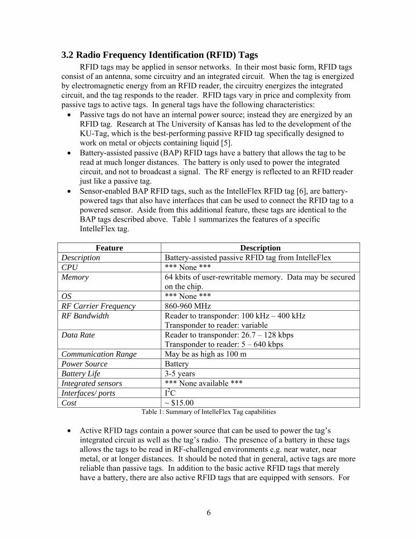
• Sensor-enabled BAP RFID tags, such as the IntelleFlex RFID tag [6], are battery-powered tags that also have interfaces that can be used to connect the RFID tag to a powered sensor. Aside from this additional feature, these tags are identical to the BAP tags described above. Table 1 summarizes the features of a specific IntelleFlex tag.
Feature Description
Description Battery-assisted passive RFID tag from IntelleFlex CPU *** None *** Memory 64 kbits of user-rewritable memory. Data may be secured
on the chip. OS *** None *** RF Carrier Frequency 860-960 MHz RF Bandwidth Reader to transponder: 100 kHz – 400 kHz
Transponder to reader: variable Data Rate Reader to transponder: 26.7 – 128 kbps
Transponder to reader: 5 – 640 kbps Communication Range May be as high as 100 m Power Source Battery Battery Life 3-5 years Integrated sensors *** None available *** Interfaces/ ports I2C Cost ~ $15.00
Table 1: Summary of IntelleFlex Tag capabilities • Active RFID tags contain a power source that can be used to power the tag’s
integrated circuit as well as the tag’s radio. The presence of a battery in these tags allows the tags to be read in RF-challenged environments e.g. near water, near metal, or at longer distances. It should be noted that in general, active tags are more reliable than passive tags. In addition to the basic active RFID tags that merely have a battery, there are also active RFID tags that are equipped with sensors. For
6
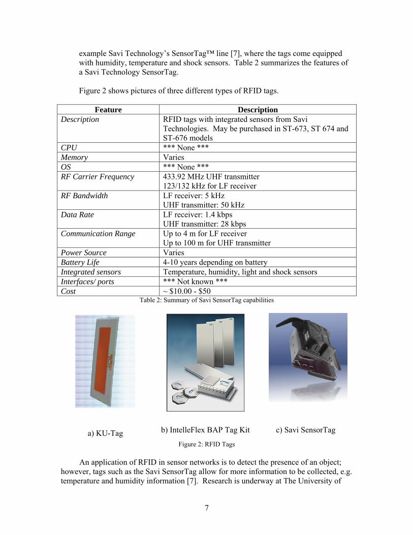
example Savi Technology’s SensorTag™ line [7], where the tags come equipped with humidity, temperature and shock sensors. Table 2 summarizes the features of a Savi Technology SensorTag.
Figure 2 shows pictures of three different types of RFID tags.
Feature Description
Description RFID tags with integrated sensors from Savi Technologies. May be purchased in ST-673, ST 674 and ST-676 models
CPU *** None *** Memory Varies OS *** None *** RF Carrier Frequency 433.92 MHz UHF transmitter
123/132 kHz for LF receiver RF Bandwidth LF receiver: 5 kHz
UHF transmitter: 50 kHz Data Rate LF receiver: 1.4 kbps
UHF transmitter: 28 kbps Communication Range Up to 4 m for LF receiver
Up to 100 m for UHF transmitter Power Source Varies Battery Life 4-10 years depending on battery Integrated sensors Temperature, humidity, light and shock sensors Interfaces/ ports *** Not known *** Cost ~ $10.00 - $50
Table 2: Summary of Savi SensorTag capabilities
a) KU-Tag
b) IntelleFlex BAP Tag Kit
c) Savi SensorTag
Figure 2: RFID Tags
An application of RFID in sensor networks is to detect the presence of an object; however, tags such as the Savi SensorTag allow for more information to be collected, e.g. temperature and humidity information [7]. Research is underway at The University of
7
Kansas to connect RFID tags to sensors to tell if the sensor is in one of a small set of states [8]. It should be noted that currently there are no RFID counterparts of the platforms that we describe below, ranging from motes to SensorNet nodes [9].
3.2.1 Motes Crossbow Technology’s MICA2 and MICAz motes were an early set of widely
available sensor platforms. Motes are battery-powered sensor networking platforms designed for use in sensor networks meant for pre-defined tasks. The main difference between the MICA2 and the MICAz motes were that the latter had support for ZigBee – an open standard [10], – whereas the MICA2 motes did not. Each mote consists of a battery pack and a circuit board that has the microcontroller, radio transceiver, and an expansion connector that can be used to attach sensors. Table 3 summarizes the basic functions of the MICA2 and MICAz motes.
Feature Description Description The MICA2 mote is a battery-powered sensor network
platform that has an ATmega128L microcontroller, as well as an 868/916 MHz transceiver and connectors for other sensor boards. The MICAz mote is identical to the MICA2 mote, except that the 868/916 MHz transceiver is replaced with a 2400-2483.5 MHz transceiver.
CPU ATmega 128L microcontroller Memory 128KB program flash
512KB measurement data OS TinyOS RF Carrier Frequency 868/916 MHz transceiver for MICA2 mote
2400 – 2483.5 MHz transceiver for MICAz mote (IEEE 802.15.4 compliant radio)
RF Bandwidth 500 kHz for the MICA2 motes 2 MHz for the MICAz mote.
Data Rate 38.4 kbps for MICA2 mote 250 kbps for MICAz mote
Communication Range ~150 m for MICA2 mote Up to 30 m indoors, and up to 100 m outdoors for the MICAz mote
Power Source 2 * AA batteries Battery Life Over one year, using sleep modes Integrated sensors Both motes provide expansion connectors for light,
temperature, relative humidity, barometric pressure, acoustic, acceleration/seismic, magnetic, and other sensor boards from Crossbow.
Interfaces/ ports I2C, SPI, UART (for serial communications) Cost $ 178 for MICA2 mote, including connector and housing.
$ 162 for MICAz mote, including connector and housing. Table 3: Summary of Mote Capabilities
8
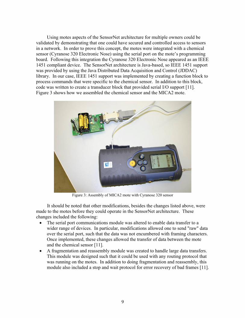
Using motes aspects of the SensorNet architecture for multiple owners could be
validated by demonstrating that one could have secured and controlled access to sensors in a network. In order to prove this concept, the motes were integrated with a chemical sensor (Cyranose 320 Electronic Nose) using the serial port on the mote’s programming board. Following this integration the Cyranose 320 Electronic Nose appeared as an IEEE 1451 compliant device. The SensorNet architecture is Java-based, so IEEE 1451 support was provided by using the Java Distributed Data Acquisition and Control (JDDAC) library. In our case, IEEE 1451 support was implemented by creating a function block to process commands that were specific to the chemical sensor. In addition to this block, code was written to create a transducer block that provided serial I/O support [11]. Figure 3 shows how we assembled the chemical sensor and the MICA2 mote.
Figure 3: Assembly of MICA2 mote with Cyranose 320 sensor
It should be noted that other modifications, besides the changes listed above, were
made to the motes before they could operate in the SensorNet architecture. These changes included the following: • The serial port communications module was altered to enable data transfer to a
wider range of devices. In particular, modifications allowed one to send "raw" data over the serial port, such that the data was not encumbered with framing characters. Once implemented, these changes allowed the transfer of data between the mote and the chemical sensor [11].
• A fragmentation and reassembly module was created to handle large data transfers. This module was designed such that it could be used with any routing protocol that was running on the motes. In addition to doing fragmentation and reassembly, this module also included a stop and wait protocol for error recovery of bad frames [11].
9
It can be seen from Table 3 that the motes met most of the functional considerations; however, the motes were also selected because of active support for motes and TinyOS in the sensor networking research community; see [12]. There are many applications of motes in sensor networking efforts. For example motes have been used in conjunction with mobile robots, in a mobile, wireless sensor network [13]. They have also been used as static sensor platforms in a sensor network with mobile sensors [14].
3.2.2 Gumstix and Robostix In addition to the motes, we reviewed gumstix computers as sensor nodes. Gumstix
are small – about the size of a stick of gum – computers that are built by Gumstix, Inc [15]. The market for gumstix computers comprises hobbyists, the military, educational institutions, and OEM manufacturers who seek small-sized computers that run Linux. Currently the gumstix computers run Linux 2.6. The robostix on the other hand is a peripheral board for the gumstix that has an Atmega128 microcontroller as well as general purpose input/output (GPIO) pins that are used for connecting sensors [16]. Table 4 summarizes the basic features and capabilities of the gumstix platform.
Feature Description
Description Consists of a gumstix motherboard and a peripheral board for console access.
CPU PXA255 XScale® at 400 MHz Memory 64 MB of RAM
16 MB of flash OS Linux 2.6.18 RF Carrier Frequency 2.4 GHz (IEEE 802.11 compliant radio) RF Bandwidth 5 MHz for Bluetooth
5 MHz for 802.11 b/g Data Rate Up to 54 Mbps if 802.11g i.e. the wifistix card is used Communication Range Up to 30 m with 802.11g. Power Source 4.5 V DC for gumstix and expansion boards.
5.0 V DC when gumstix is used with robostix. Battery Life *** No battery packs are available *** Integrated sensors None integrated. Sensors may be purchased separately
and connected either via the robostix board, or a breakout-gs board.
Interfaces/ ports Ethernet on the netMMC, netDuo or netCF cards. I2C support if the gumstix is used with the appropriate peripheral board, i.e., either the breakout card or the robostix card. Bluetooth on the console-st card USB slave on the console-st card. Serial communications using the console-st card
Cost $199 for the motherboard. Peripheral boards range in price from $15 to $99. Sensors need to be purchased separately.
10
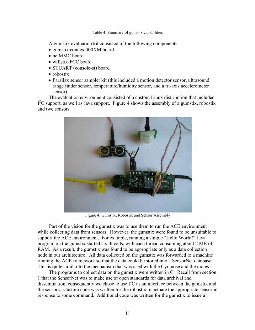
Table 4: Summary of gumstix capabilities
A gumstix evaluation kit consisted of the following components: • gumstix connex 400XM board • netMMC board • wifistix-FCC board • STUART (console-st) board • robostix • Parallax sensor sampler kit (this included a motion detector sensor, ultrasound
range finder sensor, temperature/humidity sensor, and a tri-axis accelerometer sensor).
The evaluation environment consisted of a custom Linux distribution that included I2C support, as well as Java support. Figure 4 shows the assembly of a gumstix, robostix and two sensors.
Figure 4: Gumstix, Robostix and Sensor Assembly
Part of the vision for the gumstix was to use them to run the ACE environment
while collecting data from sensors. However, the gumstix were found to be unsuitable to support the ACE environment. For example, running a simple “Hello World!” Java program on the gumstix started six threads, with each thread consuming about 2 MB of RAM. As a result, the gumstix was found to be appropriate only as a data collection node in our architecture. All data collected on the gumstix was forwarded to a machine running the ACE framework so that the data could be stored into a SensorNet database. This is quite similar to the mechanism that was used with the Cyranose and the motes.
The programs to collect data on the gumstix were written in C. Recall from section 1 that the SensorNet was to make use of open standards for data archival and dissemination, consequently we chose to use I2C as an interface between the gumstix and the sensors. Custom code was written for the robostix to actuate the appropriate sensor in response to some command. Additional code was written for the gumstix to issue a
11
command to the robostix, as well as receive a response from the robostix. This code was then tested with both the ultrasound range finder and motion detector sensors.
It should be noted that the gumstix and robostix are not very mature products, and they require some modifications before they can be used as components in the SensorNet architecture. These changes range from low-level hardware modification to higher-level software alterations. For the most part, though, these modifications are relatively minor, one-time changes; however, they are documented here so that others are aware of this need. Some of the modifications included: • Soldering 10 kΩ resistors to the robostix boards so that they could be used in
conjunction with the gumstix. • Creating a jumper cable in order to program the robostix from the gumstix. • Setting up the buildroot i.e. cross-compiler environment so that one could compile
the operating system and other programs for the gumstix [17]. • Compiling a Linux driver for the robostix board [18]. • The biggest challenge came from compiling Java support for the gumstix. The Java
virtual machine, JamVM compiled quite easily, but GNU Classpath, which contained all the class definitions, did not compile as easily. This issue was eventually resolved with some help from the gumstix mailing list. The reader is referred to [19] and appendix B for more details.
Of all the sensor platforms that were evaluated, the gumstix was the most flexible
platform in terms of the number of programming languages and interfaces that were supported. However, this flexibility comes at the cost of not having software manuals, and having to depend on the gumstix mailing list for help in resolving issues.
From the last paragraph, we note that there is an active community supporting the gumstix project. In addition to this, gumstix and robostix have found themselves in use in other projects, for example they are used to control a swarm of small airplanes while performing some computing tasks [20], as well as to control a swarm of small robots [21]; they are also used in a sensor network in northern England to monitor flooding [22].
3.2.3 Sun SPOTs Sun Microsystems recently released the Sun™ Small Programmable Object
Technology (Sun SPOT) for sensor network research [23]. Sun SPOTs are available in two different models; a free-range Sun SPOT and a base station Sun SPOT. The base station Sun SPOT is thinner than the free-range Sun SPOT, and is designed to communicate with a host computer over a USB connection. The free-range Sun SPOTs also possess a USB port that is to be used for charging the Sun SPOT, and for handling transfers between the development workstation and the Sun SPOT. It should be noted that the USB port on the Sun SPOT is for charging or communicating with the Sun SPOT. The USB connection is not used to connect other sensors; these may be attached by using the general purpose input/output (GPIO) pins on the Sun SPOT.
The Sun SPOT is designed to run a Java virtual machine that also provides operating system functionality. Each Sun SPOT consists of a sensor board, a processor board, and a battery. The capabilities of the Sun SPOT are summarized in Table 5, while Figure 5 shows a free-range Sun SPOT and a base station Sun SPOT. The cover has been taken off the free-range Sun SPOT to reveal some of its internal layout.
12

Feature Description Description Small computing platform built by Sun Microsystems for
sensor networking research. Each Sun SPOT is a self-contained unit with a sensor board, a processor board and a radio.
CPU 180 MHz 32 bit ARM 920T processor Memory 512 kB of RAM
4 MB of flash OS J2ME CLDC (Connected Limited Device Configuration)
1.1 Java Virtual Machine with OS functionality RF Carrier Frequency 2.4 GHz (IEEE 802.15.4 compliant radio) RF Bandwidth 2 MHz Data Rate Bit rates of up to 250 kbps are typical for IEEE 802.15.4 Communication Range About 30 m indoors Power Source 3.7 V 720 mAh rechargeable lithium-ion battery Battery Life *** Not specified *** Integrated sensors 2G/6G 3 axis accelerometer
Light sensor Temperature sensor
Interfaces/ ports USB 6 analog inputs 2 momentary switches 5 GPIO pins 4 high current output pins
Cost $ 670 for a development kit. This includes one base station unit, and two free-range Sun SPOTs.
Table 5: Summary of Sun SPOT capabilities
Figure 5: Base station and Free-Range Sun SPOTs
13
From Table 5 we see that the Sun SPOT is memory-constrained; as a result the Sun SPOT could not be used to run the ACE environment, which takes up about 41 MB. Instead, the Sun SPOTs were to be integrated into the architecture using an intermediate computer running the ACE framework i.e., the scenario shown in Figure 1-c. As was the case for the motes and the gumstix, there is an active community supporting Sun SPOT development [24]. Owing to their recent release, reports discussing how they have been implemented in sensor networks have not yet appeared; however, Sun SPOTs have been used in a variety of projects ranging from deploying Sun SPOTs to model rockets for collecting acceleration data, to classroom projects to explore the future of electronic devices [25].
3.2.4 Personal Digital Assistants Personal digital assistants (PDAs) were evaluated during the course of this effort,
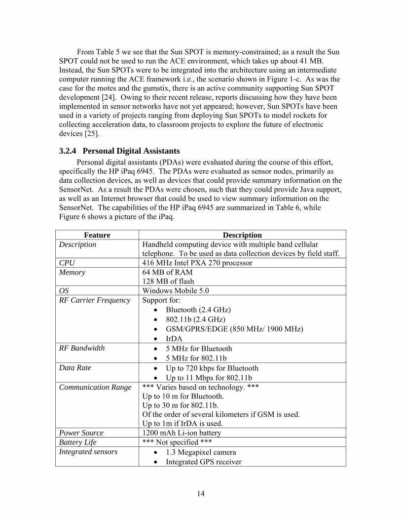
specifically the HP iPaq 6945. The PDAs were evaluated as sensor nodes, primarily as data collection devices, as well as devices that could provide summary information on the SensorNet. As a result the PDAs were chosen, such that they could provide Java support, as well as an Internet browser that could be used to view summary information on the SensorNet. The capabilities of the HP iPaq 6945 are summarized in Table 6, while Figure 6 shows a picture of the iPaq.
Feature Description Description Handheld computing device with multiple band cellular
telephone. To be used as data collection devices by field staff. CPU 416 MHz Intel PXA 270 processor Memory 64 MB of RAM
128 MB of flash OS Windows Mobile 5.0 RF Carrier Frequency Support for:
• Bluetooth (2.4 GHz) • 802.11b (2.4 GHz) • GSM/GPRS/EDGE (850 MHz/ 1900 MHz) • IrDA
RF Bandwidth • 5 MHz for Bluetooth • 5 MHz for 802.11b
Data Rate • Up to 720 kbps for Bluetooth • Up to 11 Mbps for 802.11b
Communication Range *** Varies based on technology. *** Up to 10 m for Bluetooth. Up to 30 m for 802.11b. Of the order of several kilometers if GSM is used. Up to 1m if IrDA is used.
Power Source 1200 mAh Li-ion battery Battery Life *** Not specified *** Integrated sensors • 1.3 Megapixel camera
• Integrated GPS receiver
14

Interfaces/ ports USB, mini-SD slot Cost $ 600
Table 6: Summary of HP iPaq 6945 capabilities
Figure 6: HP iPaq 6945
The HP iPaqs were pre-installed with the Esmertec Java virtual machine. In order
to integrate the iPaqs into the architecture, some Java programs were written to transfer pictures – the programs are more general than this, and can transfer any type of file – from the iPaq to a server on a user-defined port. Hence we were able to demonstrate that the iPaqs could operate in the SensorNet architecture as data collection devices.
Besides our work with iPaqs, we can also find active use of iPaqs in the sensor networking community. References [26] and [27] indicate that iPaqs are the PDAs of choice for development in sensor network research. We can also see that iPaqs have been used in the DARPA SenseIT effort [28] as well as to demonstrate the feasibility of data fusion in sensor networks [29].
Unlike the gumstix, the iPaq is a very mature product, and did not require any modifications to operate in the SensorNet architecture. However, the iPaqs are best suited as end-user devices either for collecting sensor data or for displaying sensor data to users of the SensorNet. The iPaqs will not have sufficient computing power to operate as full SensorNet nodes, which will be discussed in the next subsection.
3.2.5 SensorNet Nodes Sensor nodes are the core data collection piece of the SensorNet architecture [2].
These sensor nodes will typically host one or more sensors, with each node being autonomous and self-contained. Each SensorNet node will possess "a processor unit and hard disk, power supplies, modem, serial interface and LAN interface" [2]. SensorNet nodes will run a customized Linux distribution [2], software for controlling agents, as well as a MySQL database for data logging. All the node software for implementing web service clients will be implemented using Java [2].
15
Each SensorNet node will be responsible for registering itself when it joins the SensorNet. In addition, SensorNet nodes will also have to support discovery of the other nodes on the SensorNet. In order to improve the fault tolerance of each SensorNet node, each node will have at least two methods for communicating with a data center using standards-based Web services. Each of the communication links will be monitored by a link monitor module. If the primary link fails, the link monitor will transfer communications to another link, and notify the SensorNet that the node has changed its address [2].
SensorNet nodes will communicate with attached sensors via a Generic Software Abstraction Layer (GSAL) that will provide IEEE 1451 interfaces to the higher layer software running on a node – the IEEE 1451 standards are an open set of standards for connecting smart sensors to networks. It should be noted that SensorNet nodes need not necessarily have a physical connection to a sensor. The Concept Definition document [2] indicates that nodes and sensors may be separated by a few miles.
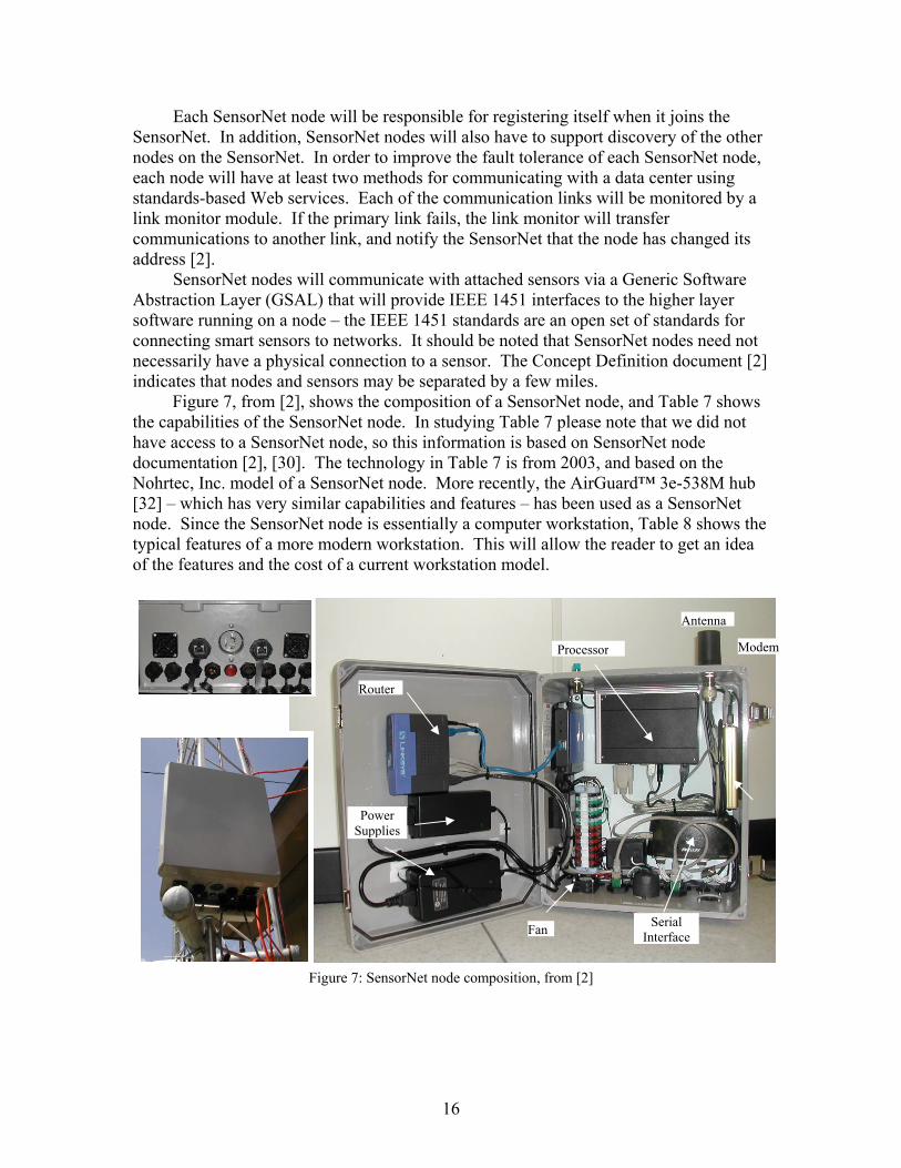
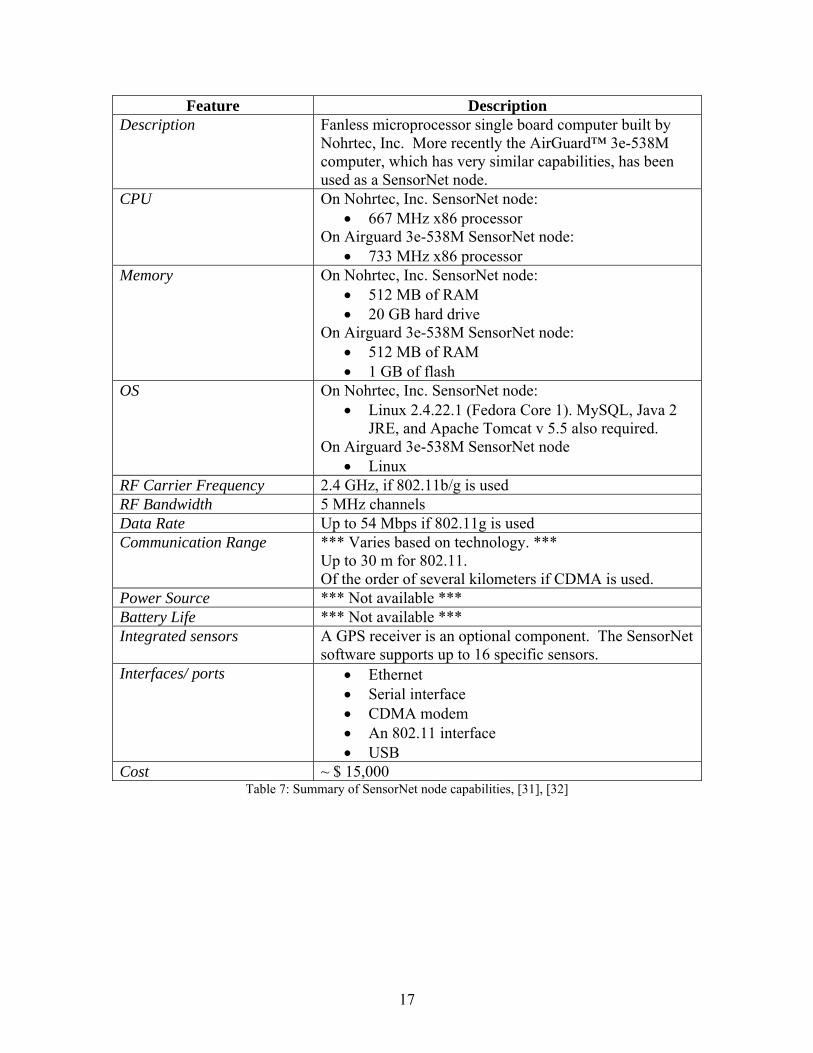
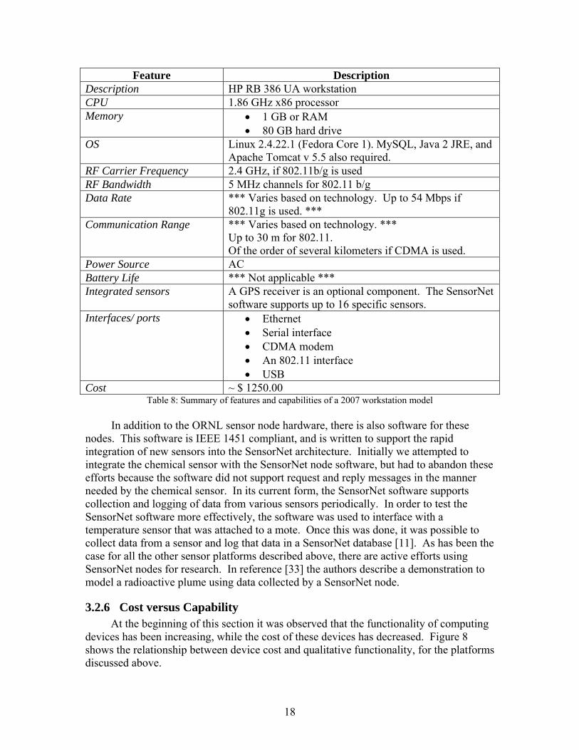
Figure 7, from [2], shows the composition of a SensorNet node, and Table 7 shows the capabilities of the SensorNet node. In studying Table 7 please note that we did not have access to a SensorNet node, so this information is based on SensorNet node documentation [2], [30]. The technology in Table 7 is from 2003, and based on the Nohrtec, Inc. model of a SensorNet node. More recently, the AirGuard™ 3e-538M hub [32] – which has very similar capabilities and features – has been used as a SensorNet node. Since the SensorNet node is essentially a computer workstation, Table 8 shows the typical features of a more modern workstation. This will allow the reader to get an idea of the features and the cost of a current workstation model.
Figure 7: SensorNet node composition, from [2]
Router
Modem
Serial Interface
Power Supplies
Processor
Antenna
Fan
16
Feature Description Description Fanless microprocessor single board computer built by
Nohrtec, Inc. More recently the AirGuard™ 3e-538M computer, which has very similar capabilities, has been used as a SensorNet node.
CPU On Nohrtec, Inc. SensorNet node: • 667 MHz x86 processor
On Airguard 3e-538M SensorNet node: • 733 MHz x86 processor
Memory On Nohrtec, Inc. SensorNet node: • 512 MB of RAM • 20 GB hard drive
On Airguard 3e-538M SensorNet node: • 512 MB of RAM • 1 GB of flash
OS On Nohrtec, Inc. SensorNet node: • Linux 2.4.22.1 (Fedora Core 1). MySQL, Java 2
JRE, and Apache Tomcat v 5.5 also required. On Airguard 3e-538M SensorNet node
• Linux RF Carrier Frequency 2.4 GHz, if 802.11b/g is used RF Bandwidth 5 MHz channels Data Rate Up to 54 Mbps if 802.11g is used Communication Range *** Varies based on technology. ***
Up to 30 m for 802.11. Of the order of several kilometers if CDMA is used.
Power Source *** Not available *** Battery Life *** Not available *** Integrated sensors A GPS receiver is an optional component. The SensorNet
software supports up to 16 specific sensors. Interfaces/ ports • Ethernet
• Serial interface • CDMA modem • An 802.11 interface • USB
Cost ~ $ 15,000 Table 7: Summary of SensorNet node capabilities, [31], [32]
17
Feature Description Description HP RB 386 UA workstation CPU 1.86 GHz x86 processor Memory • 1 GB or RAM
• 80 GB hard drive OS Linux 2.4.22.1 (Fedora Core 1). MySQL, Java 2 JRE, and
Apache Tomcat v 5.5 also required. RF Carrier Frequency 2.4 GHz, if 802.11b/g is used RF Bandwidth 5 MHz channels for 802.11 b/g Data Rate *** Varies based on technology. Up to 54 Mbps if
802.11g is used. *** Communication Range *** Varies based on technology. ***
Up to 30 m for 802.11. Of the order of several kilometers if CDMA is used.
Power Source AC Battery Life *** Not applicable *** Integrated sensors A GPS receiver is an optional component. The SensorNet
software supports up to 16 specific sensors. Interfaces/ ports • Ethernet
• Serial interface • CDMA modem • An 802.11 interface • USB
Cost ~ $ 1250.00 Table 8: Summary of features and capabilities of a 2007 workstation model
In addition to the ORNL sensor node hardware, there is also software for these
nodes. This software is IEEE 1451 compliant, and is written to support the rapid integration of new sensors into the SensorNet architecture. Initially we attempted to integrate the chemical sensor with the SensorNet node software, but had to abandon these efforts because the software did not support request and reply messages in the manner needed by the chemical sensor. In its current form, the SensorNet software supports collection and logging of data from various sensors periodically. In order to test the SensorNet software more effectively, the software was used to interface with a temperature sensor that was attached to a mote. Once this was done, it was possible to collect data from a sensor and log that data in a SensorNet database [11]. As has been the case for all the other sensor platforms described above, there are active efforts using SensorNet nodes for research. In reference [33] the authors describe a demonstration to model a radioactive plume using data collected by a SensorNet node.
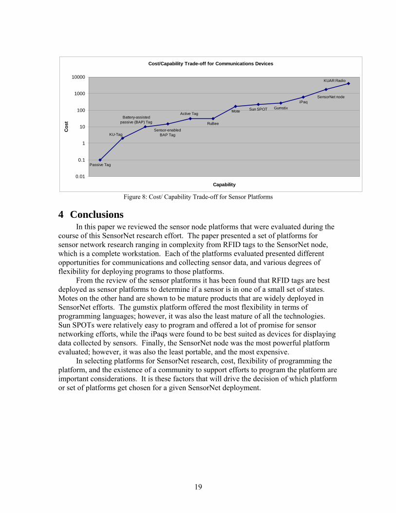
3.2.6 Cost versus Capability At the beginning of this section it was observed that the functionality of computing
devices has been increasing, while the cost of these devices has decreased. Figure 8 shows the relationship between device cost and qualitative functionality, for the platforms discussed above.
18
Cost/Capability Trade-off for Communications Devices
Passive Tag
RuBee
Mote Sun SPOT GumstixiPaq
Sensor-enabledBAP Tag
Battery-assisted passive (BAP) Tag
KU-Tag
Active Tag
KUAR Radio
SensorNet node
0.01
0.1
1
10
100
1000
10000
Capability
Cos
t
Figure 8: Cost/ Capability Trade-off for Sensor Platforms
4 Conclusions In this paper we reviewed the sensor node platforms that were evaluated during the
course of this SensorNet research effort. The paper presented a set of platforms for sensor network research ranging in complexity from RFID tags to the SensorNet node, which is a complete workstation. Each of the platforms evaluated presented different opportunities for communications and collecting sensor data, and various degrees of flexibility for deploying programs to those platforms.
From the review of the sensor platforms it has been found that RFID tags are best deployed as sensor platforms to determine if a sensor is in one of a small set of states. Motes on the other hand are shown to be mature products that are widely deployed in SensorNet efforts. The gumstix platform offered the most flexibility in terms of programming languages; however, it was also the least mature of all the technologies. Sun SPOTs were relatively easy to program and offered a lot of promise for sensor networking efforts, while the iPaqs were found to be best suited as devices for displaying data collected by sensors. Finally, the SensorNet node was the most powerful platform evaluated; however, it was also the least portable, and the most expensive.
In selecting platforms for SensorNet research, cost, flexibility of programming the platform, and the existence of a community to support efforts to program the platform are important considerations. It is these factors that will drive the decision of which platform or set of platforms get chosen for a given SensorNet deployment.
19
5 References [1] F. Zhao and L. Guibas, “Wireless Sensor Networks: An Information Processing
Approach (The Morgan Kaufmann Series in Networking),” Morgan-Kauffman, 2005.
[2] “SensorNet: Concept Definition Document”, Computational Sciences and Engineering Division, Oak Ridge National Laboratory, Oak Ridge, TN, June 2004.
[3] G. J. Minden and V. S. Frost, (2006, Oct.). “A Unified Architecture for SensorNet with Multiple Owners.” [Online]. Available: http://www.ittc.ku.edu/sensornet/unified_architecture/talks/Sentinel_ORNL_KS_10-19-06.pdf
[4] J. Mauro, “Security Model in the Ambient Computational Environment,” master’s thesis, Dept. of Electrical Eng. & Computer Science, The University of Kansas, 2004.
[5] M. Eunni et al. “A Novel Planar Microstrip Antenna Design for UHF RFID,” Journal Systemics, Cybernetics and Informatics, vol. 5, no. 1, pp. 6-10, Jan. 2007.
[6] Intelleflex Corporation: Technology, (2007, Aug.). InfoSure Single Chip RFID Tag Data Sheet. [Online]. Available: http://www.intelleflex.com/pages/InfosureDataSheet.pdf.
[7] Savi Technology, (2007, July). Savi Technology: SensorTags™. [Online]. Available: http://www.savi.com/products/pr.rfid.security.shtml.
[8] D. Deavours, private communication, July 2007. [9] R. Clauberg, “RFID and Sensor Networks,” in Proc. RFID Workshop, St. Gallen,
Switzerland, Sep. 27 2004. [10] Crossbow Technology, Inc. (2007, Aug.). Crossbow Technology: Wireless Sensor
Networks: MICAz 2.4 GHz – Wireless Module. [Online]. Available: http://www.xbow.com/Products/productdetails.aspx?sid=164.
[11] P. Mani, “ORNL – SensorNet: Accomplishments and Updates – A Technical Report,” Unpublished.
[12] TinyOS Community Forum, (2007, July). An Open Source OS for the Networked Sensor Regime. [Online]. Available: http://www.tinyos.net.
[13] D. Johnson et al., “Mobile Emulab: A Robotic Wireless and Sensor Network Testbed.” In Proc. of IEEE INFOCOM ’06.
[14] Y. Tseng et al., “iMouse: An Integrated Mobile Surveillance and Wireless Sensor System,” IEEE Computer, vol. 40, no. 6, pp. 60-66, June 2007.
[15] Gumstix, Inc. (2007, Aug.). Gumstix: Way Small Computing. [Online]. Available: http://gumstix.com/about.html.
[16] Gumstix, Inc. (2007, Aug.). Robostix Summary. [Online]. Available: http://gumstix.com/store/catalog/product_info.php?products_id=139.
[17] Gumstix, Inc. (2007, Aug.). Buildroot. [Online]. Available: http://docwiki.gumstix.org/Buildroot.
[18] Gumstix, Inc. (2007, Aug.). Robostix Gumstix ISP. [Online]. Available: http://docwiki.gumstix.org/Robostix_gumstix_ISP.
[19] Gumstix, Inc. (2007, Aug.). Java - GumstixDocsWiki. [Online]. Available: http://docwiki.gumstix.org/Java.
20
[20] O. Holland et al., “Beyond Swarm Intelligence: The Ultraswarm,” In Proc. Of IEEE Swarm Intelligence Symposium (SIS 2005).
[21] FlockBots, (2005, July). Home. [Online]. Available: http://cs.gmu.edu/~eclab/projects/robots/flockbots/pmwiki.php?n=Main.Home
[22] P. Greenwood et al. “Using a Grid-Enabled Wireless Sensor Network for Flood Management,” Demo at Eighth International Conference on Ubiquitous Computing (UBICOMP ’06) Demo Session, Orange County, California, USA, Sept. 2006.
[23] Sun ™ Microsystems, (2007, July). Project Sun SPOT Products. [Online]. Available: http://www.sunspotworld.com/products/.
[24] Project Sun SPOT Forum, (2007, July). SunSpotWorld.com Forum Index. [Online]. Available: http://www.sunspotworld.com/forums/
[25] Project Sun SPOT, (2007, Aug.). SunSpotWorld – Sun SPOTs in Action. [Online]. Available: http://www.sunspotworld.com/action/index.php?show=all.
[26] J. Lepreau, private communication, Aug. 2006. [27] H. Balakrishnan, private communication, Aug. 2006. [28] A. Boulis et al., “Design and Implementation of a Framework for Efficient and
Programmable Sensor Networks,” in Proc. First Int’l Conf. Mobile Systems, Applications, and Services (MobiSys 2003), San Francisco, CA, May 5-8, 2003, pp. 187-200.
[29] U. Ramachandran et al., “Dynamic Data Fusion for Future Sensor Networks,” ACM Trans. Sensor Networks, vol. 2, no. 3, pp. 404-443, Aug. 2006.
[30] “SensorNet Node Functional Components”, Computational Sciences and Engineering Division, Oak Ridge National Laboratory, Oak Ridge, TN, Spring 2004.
[31] M. Shankar et al., “The SensorNet Node: Last-Mile Platform for Sensor Networks Interoperability,” Unpublished.
[32] 3e Technologies International, (2007, Aug.). AirGuard™ 3e–538M: The Smart & Secure Wireless Video / Sensor Node. [Online]. Available: http://www.3eti.com/pdf/3e-538M.pdf.
[33] J. Chin et al. “A Sensor-cyber Network Testbed for Plume Detection, Identification, and Tracking,” in Proc. Information Processing in Sensor Networks (ISPN 2007), Cambridge, MA, April 2007, pp. 541-542.
21
6 Appendices
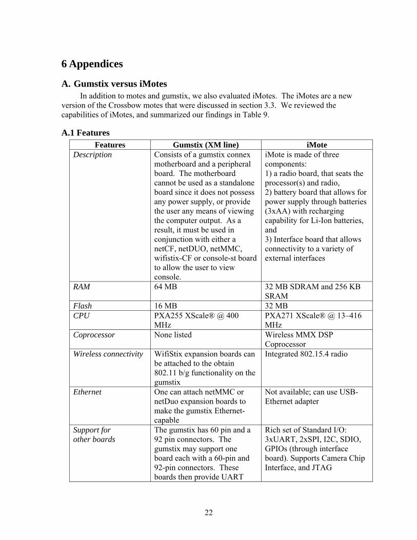
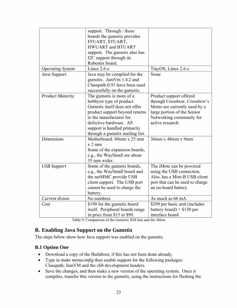
A. Gumstix versus iMotes In addition to motes and gumstix, we also evaluated iMotes. The iMotes are a new
version of the Crossbow motes that were discussed in section 3.3. We reviewed the capabilities of iMotes, and summarized our findings in Table 9.
A.1 Features Features Gumstix (XM line) iMote
Description Consists of a gumstix connex motherboard and a peripheral board. The motherboard cannot be used as a standalone board since it does not possess any power supply, or provide the user any means of viewing the computer output. As a result, it must be used in conjunction with either a netCF, netDUO, netMMC, wifistix-CF or console-st board to allow the user to view console.
iMote is made of three components: 1) a radio board, that seats the processor(s) and radio, 2) battery board that allows for power supply through batteries (3xAA) with recharging capability for Li-Ion batteries, and 3) Interface board that allows connectivity to a variety of external interfaces
RAM 64 MB 32 MB SDRAM and 256 KB SRAM
Flash 16 MB 32 MB CPU PXA255 XScale® @ 400
MHz PXA271 XScale® @ 13–416 MHz
Coprocessor None listed Wireless MMX DSP Coprocessor
Wireless connectivity WifiStix expansion boards can be attached to the obtain 802.11 b/g functionality on the gumstix
Integrated 802.15.4 radio
Ethernet One can attach netMMC or netDuo expansion boards to make the gumstix Ethernet-capable
Not available; can use USB-Ethernet adapter
Support for other boards
The gumstix has 60 pin and a 92 pin connectors. The gumstix may support one board each with a 60-pin and 92-pin connectors. These boards then provide UART
Rich set of Standard I/O: 3xUART, 2xSPI, I2C, SDIO, GPIOs (through interface board). Supports Camera Chip Interface, and JTAG
22
support. Through / these boards the gumstix provides FFUART, STUART, HWUART and BTUART support. The gumstix also has I2C support through its Robostix board.
Operating System Linux 2.6.x TinyOS, Linux 2.6.xJava Support Java may be compiled for the
gumstix. JamVm 1.4.2 and Classpath-0.91 have been used successfully on the gumstix.
None
Product Maturity The gumstix is more of a hobbyist type of product. Gumstix itself does not offer product support beyond returns to the manufacturer for defective hardware. All support is handled primarily through a gumstix mailing list.
Product support offered through Crossbow. Crossbow’s Motes are currently used by a large portion of the Sensor Networking community for active research.
Dimensions Motherboard: 80mm x 25 mm x 2 mm Some of the expansion boards, e.g., the WaySmall are about 35 mm wider.
36mm x 48mm x 9mm
USB Support Some of the gumstix boards, e.g., the WaySmall board and the netMMC provide USB client support. The USB port cannot be used to charge the battery.
The iMote can be powered using the USB connection. Also, has a Mini-B USB client port that can be used to charge an on-board battery.
Current drawn No numbers As much as 66 mACost $199 for the gumstix board
itself. Peripheral boards range in price from $15 to $99.
$299 per basic unit (includes battery board) + $150 per interface board
Table 9: Comparison of the Gumstix XM line and the iMote
B. Enabling Java Support on the Gumstix The steps below show how Java support was enabled on the gumstix.
B.1 Option One • Download a copy of the Buildroot, if this has not been done already. • Type in make menuconfig then enable support for the following packages:
Classpath, JamVM and the zlib development headers. • Save the changes, and then make a new version of the operating system. Once it
compiles, transfer this version to the gumstix, using the instructions for flashing the
23
gumstix. • The instructions found above are from the Gumstix wiki
(http://docwiki.gumstix.org/Java). If the instructions above fail, proceed to Option Two.
B.2 Option Two • Download and install Jikes. (Do a Google search for the application, then make and
install it.) Once Jikes is installed copy the Jikes executable from /usr/local/bin to /usr/bin.
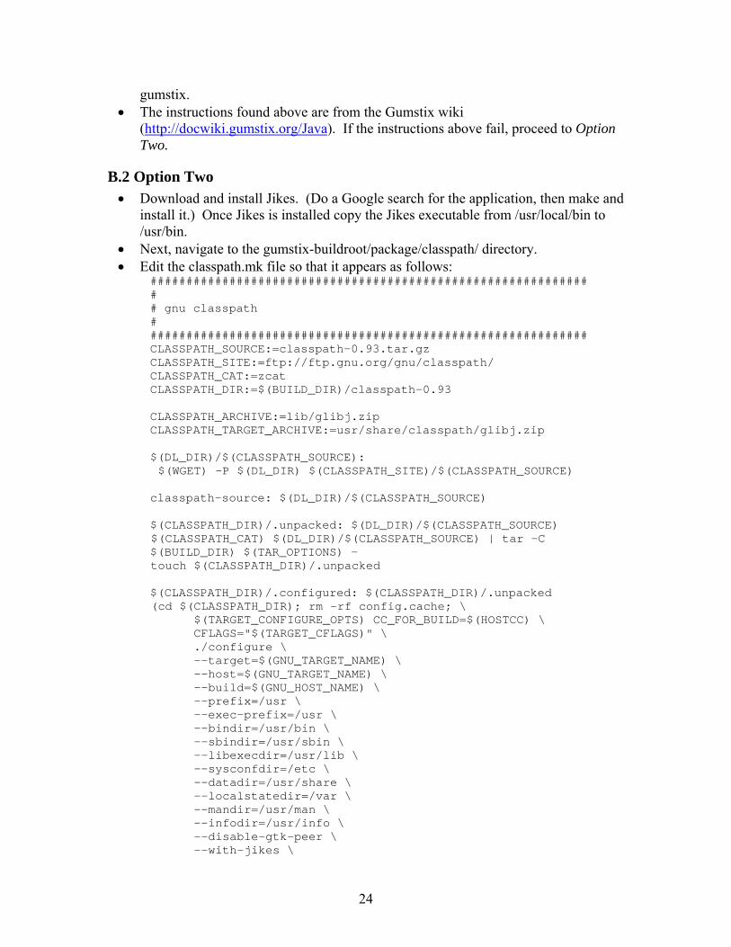
• Next, navigate to the gumstix-buildroot/package/classpath/ directory. • Edit the classpath.mk file so that it appears as follows:
############################################################# # # gnu classpath # ############################################################# CLASSPATH_SOURCE:=classpath-0.93.tar.gz CLASSPATH_SITE:=ftp://ftp.gnu.org/gnu/classpath/ CLASSPATH_CAT:=zcat CLASSPATH_DIR:=$(BUILD_DIR)/classpath-0.93 CLASSPATH_ARCHIVE:=lib/glibj.zip CLASSPATH_TARGET_ARCHIVE:=usr/share/classpath/glibj.zip $(DL_DIR)/$(CLASSPATH_SOURCE): $(WGET) -P $(DL_DIR) $(CLASSPATH_SITE)/$(CLASSPATH_SOURCE) classpath-source: $(DL_DIR)/$(CLASSPATH_SOURCE) $(CLASSPATH_DIR)/.unpacked: $(DL_DIR)/$(CLASSPATH_SOURCE) $(CLASSPATH_CAT) $(DL_DIR)/$(CLASSPATH_SOURCE) | tar -C $(BUILD_DIR) $(TAR_OPTIONS) - touch $(CLASSPATH_DIR)/.unpacked $(CLASSPATH_DIR)/.configured: $(CLASSPATH_DIR)/.unpacked (cd $(CLASSPATH_DIR); rm -rf config.cache; \ $(TARGET_CONFIGURE_OPTS) CC_FOR_BUILD=$(HOSTCC) \ CFLAGS="$(TARGET_CFLAGS)" \ ./configure \ --target=$(GNU_TARGET_NAME) \ --host=$(GNU_TARGET_NAME) \ --build=$(GNU_HOST_NAME) \ --prefix=/usr \ --exec-prefix=/usr \ --bindir=/usr/bin \ --sbindir=/usr/sbin \ --libexecdir=/usr/lib \ --sysconfdir=/etc \ --datadir=/usr/share \ --localstatedir=/var \ --mandir=/usr/man \ --infodir=/usr/info \ --disable-gtk-peer \ --with-jikes \
24
); touch $(CLASSPATH_DIR)/.configured # # CLASSPATH_ARCHIVE and CLASSPATH_TARGET_ARCHIVE are used as stand-ins # for all the files that get installed on the target system. # $(CLASSPATH_DIR)/$(CLASSPATH_ARCHIVE): $(CLASSPATH_DIR)/.configured @if $(shell which zip) == ''; then echo "zip must be installed on the build system to build classpath"; exit 1; fi $(MAKE) CC=$(TARGET_CC) CC_FOR_BUILD=$(HOSTCC) -C $(CLASSPATH_DIR) $(TARGET_DIR)/$(CLASSPATH_TARGET_ARCHIVE): $(CLASSPATH_DIR)/$(CLASSPATH_ARCHIVE) $(MAKE) DESTDIR=$(TARGET_DIR) CC=$(TARGET_CC) -C $(CLASSPATH_DIR) install rm -rf $(TARGET_DIR)/usr/share/classpath/examples classpath: uclibc $(TARGET_DIR)/$(CLASSPATH_TARGET_ARCHIVE) ############################################################# # # Toplevel Makefile options # ############################################################# ifeq ($(strip $(BR2_PACKAGE_CLASSPATH)),y) TARGETS+=classpath endif
• Save the classpath.mk file and return to the gumstix-buildroot
directory. • Type in make clean followed by make.
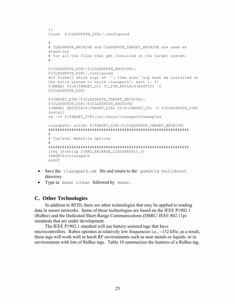
C. Other Technologies In addition to RFID, there are other technologies that may be applied to reading
data in sensor networks. Some of these technologies are based on the IEEE P1902.1 (RuBee) and the Dedicated Short-Range Communications (DSRC/ IEEE 802.11p) standards that are under development.
The IEEE P1902.1 standard will use battery-assisted tags that have microcontrollers. Rubee operates at relatively low frequencies i.e., ~132 kHz; as a result, these tags will work well in harsh RF environments such as near metals or liquids, or in environments with lots of RuBee tags. Table 10 summarizes the features of a RuBee tag.
25
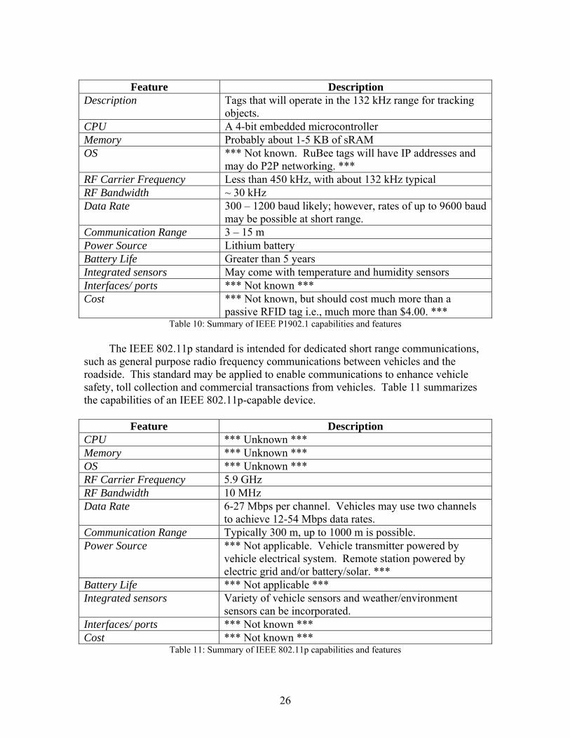
Feature Description
Description Tags that will operate in the 132 kHz range for tracking objects.
CPU A 4-bit embedded microcontroller Memory Probably about 1-5 KB of sRAM OS *** Not known. RuBee tags will have IP addresses and
may do P2P networking. *** RF Carrier Frequency Less than 450 kHz, with about 132 kHz typical RF Bandwidth ~ 30 kHz Data Rate 300 – 1200 baud likely; however, rates of up to 9600 baud
may be possible at short range. Communication Range 3 – 15 m Power Source Lithium battery Battery Life Greater than 5 years Integrated sensors May come with temperature and humidity sensors Interfaces/ ports *** Not known *** Cost *** Not known, but should cost much more than a
passive RFID tag i.e., much more than $4.00. *** Table 10: Summary of IEEE P1902.1 capabilities and features
The IEEE 802.11p standard is intended for dedicated short range communications,
such as general purpose radio frequency communications between vehicles and the roadside. This standard may be applied to enable communications to enhance vehicle safety, toll collection and commercial transactions from vehicles. Table 11 summarizes the capabilities of an IEEE 802.11p-capable device.
Feature Description CPU *** Unknown *** Memory *** Unknown *** OS *** Unknown *** RF Carrier Frequency 5.9 GHz RF Bandwidth 10 MHz Data Rate 6-27 Mbps per channel. Vehicles may use two channels
to achieve 12-54 Mbps data rates. Communication Range Typically 300 m, up to 1000 m is possible. Power Source *** Not applicable. Vehicle transmitter powered by
vehicle electrical system. Remote station powered by electric grid and/or battery/solar. ***
Battery Life *** Not applicable *** Integrated sensors Variety of vehicle sensors and weather/environment
sensors can be incorporated. Interfaces/ ports *** Not known *** Cost *** Not known ***
Table 11: Summary of IEEE 802.11p capabilities and features
26