Embed Size (px)
Citation preview
Page 148
An Enhanced Mechanism to Detect Distorted Fingerprints Sravanvardhan Rao Souda
Assistant Professor,
Ellenki College of Engineering & Technology,
Hyderabad.
Jangam Ravi
Assistant Professor,
Avanthi's Scientific Technological & Research
Academy, Hyderabad.
Abstract:
Elastic distortion of fingerprints is one of the major
causes for false non-match. While this problem affects
all fingerprint recognition applications, it is especially
dangerous in negative recognition applications, such as
watch list and deduplication applications. In such
applications, malicious users may purposely distort
their fingerprints to evade identification. In this paper,
we proposed novel algorithms to detect and rectify
skin distortion based on a single fingerprint image.
Distortion detection is viewed as a two-class
classification problem, for which the registered ridge
orientation map and period map of a fingerprint are
used as the feature vector and a SVM classifier is
trained to perform the classification task. Distortion
rectification (or equivalently distortion field
estimation) is viewed as a regression problem, where
the input is a distorted fingerprint and the output is the
distortion field.
To solve this problem, a database (called reference
database) of various distorted reference fingerprints
and corresponding distortion fields is built in the
offline stage, and then in the online stage, the nearest
neighbor of the input fingerprint is found in the
reference database and the corresponding distortion
field is used to transform the input fingerprint into a
normal one. Promising results have been obtained on
three databases containing many distorted fingerprints,
namely FVC2004 DB1, Tsinghua Distorted
Fingerprint database, and the NIST SD27 latent
fingerprint database.
Index Terms:
Fingerprint, distortion, registration, nearest neighbor
regression, PCA.
1 INTRODUCTION:
ALTHOUGH automatic fingerprint recognition
technologies have rapidly advanced during the last
forty years, there still exists several challenging
research problems, for example, recognizing low
quality fingerprints [2]. Finger-print matcher is very
sensitive to image quality as observed in the FVC2006
[3], where the matching accuracy of the same
algorithm varies significantly among different data-
sets due to variation in image quality. The difference
between the accuracies of plain, rolled and latent
fingerprint matching is even larger as observed in
technology evaluations conducted by the NIST [4].
The consequence of low quality fingerprints depends
on the type of the fingerprint recognition system. A
fingerprint recognition system can be classified as
either a positive or negative system. In a positive
recognition system, such as physical access control
systems, the user is supposed to be cooperative and
wishes to be identified.
In a negative recognition system, such as identifying
persons in watch lists and detecting multiple
enrollment under different names, the user of interest
(e.g., criminals) is supposed to be uncooperative and
does not wish to be identified. In a positive recognition
system, low quality will lead to false reject of
legitimate users and thus bring inconvenience. The
consequence of low quality for a negative recognition
system, however, is much more serious, since
malicious users may purposely reduce fingerprint
quality to prevent fingerprint system from finding the
true identity [6]. In fact, law enforcement officials
have encountered a number of cases where criminals
attempted to avoid identification by dam-aging or
surgically altering their fingerprints [7].
Page 149
Hence it is especially important for negative
fingerprint recognition systems to detect low quality
fingerprints and improve their quality so that the
fingerprint system is not compromised by malicious
users. Degradation of finger-print quality can be
photometric or geometrical. Photometric degradation
can be caused by non-ideal skin conditions, dirty
sensor surface, and complex image background
(especially in latent fingerprints). Geometrical
degradation is mainly caused by skin distortion.
Photometric degradation has been widely studied and a
number of quality evaluation algorithms [8], [9], [10]
and enhancement algorithms [11], [12], [13], [14], [15]
have been proposed. On the contrary, geometrical
degradation due to skin distortion has not yet received
sufficient attention, despite of the importance of this
problem. This is the problem this paper attempts to
address.
Note that, for a negative fingerprint recognition
system, its security level is as weak as the weakest
point. Thus it is urgent to develop distorted fingerprint
(DF) detection and rectification algorithms to fill the
hole. Elastic distortion is introduced due to the
inherent flexibility of fingertips, contact-based
fingerprint acquisition procedure, and a purposely
lateral force or torque, etc. Skin distortion increases
the intra-class variations (difference among
fingerprints from the same finger) and thus leads to
false non-matches due to limited capability of existing
fingerprint matchers in recognizing severely distorted
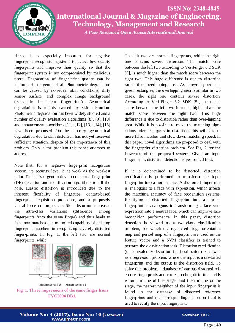
finger-prints. In Fig. 1, the left two are normal
fingerprints, while
Fig. 1. Three impressions of the same finger from
FVC2004 DB1.
The left two are normal fingerprints, while the right
one contains severe distortion. The match score
between the left two according to VeriFinger 6.2 SDK
[5], is much higher than the match score between the
right two. This huge difference is due to distortion
rather than overlapping area. As shown by red and
green rectangles, the overlapping area is similar in two
cases. the right one contains severe distortion.
According to Veri-Finger 6.2 SDK [5], the match
score between the left two is much higher than the
match score between the right two. This huge
difference is due to distortion rather than over-lapping
area. While it is possible to make the matching algo-
rithms tolerate large skin distortion, this will lead to
more false matches and slow down matching speed. In
this paper, novel algorithms are proposed to deal with
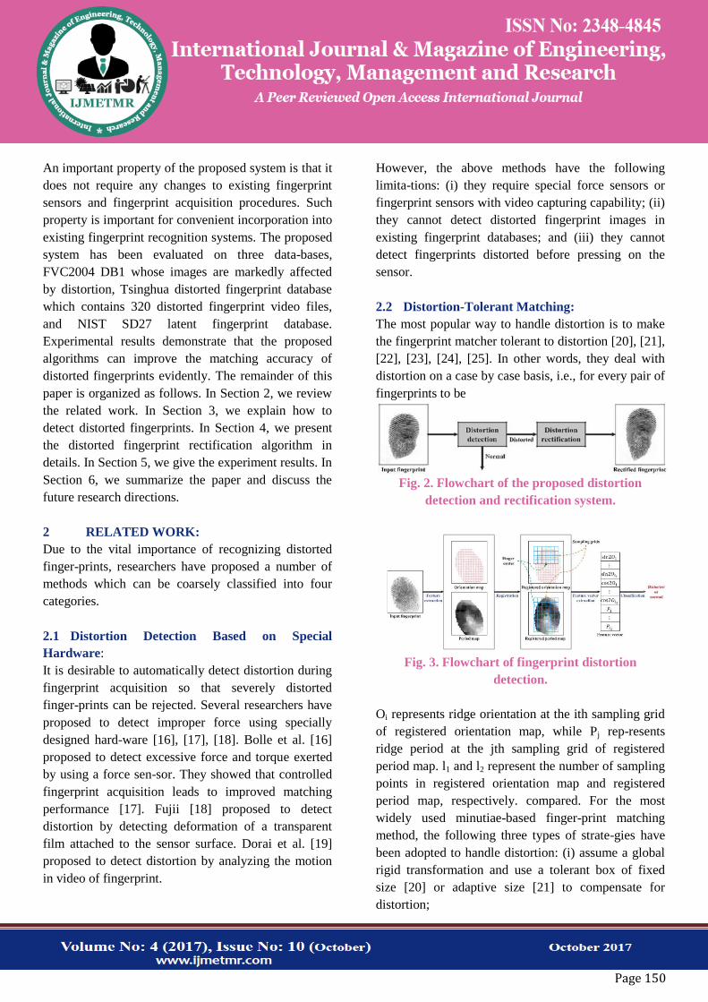
the fingerprint distortion problem. See Fig. 2 for the
flowchart of the proposed system. Given an input
finger-print, distortion detection is performed first.
If it is deter-mined to be distorted, distortion
rectification is performed to transform the input
fingerprint into a normal one. A dis-torted fingerprint
is analogous to a face with expression, which affects
the matching accuracy of face recognition systems.
Rectifying a distorted fingerprint into a normal
fingerprint is analogous to transforming a face with
expression into a neutral face, which can improve face
recognition performance. In this paper, distortion
detection is viewed as a two-class classification
problem, for which the registered ridge orientation
map and period map of a fingerprint are used as the
feature vector and a SVM classifier is trained to
perform the classification task. Distortion recti-fication
(or equivalently distortion field estimation) is viewed
as a regression problem, where the input is a dis-torted
fingerprint and the output is the distortion field. To
solve this problem, a database of various distorted ref-
erence fingerprints and corresponding distortion fields
is built in the offline stage, and then in the online
stage, the nearest neighbor of the input fingerprint is
found in the database of distorted reference
fingerprints and the corresponding distortion field is
used to rectify the input fingerprint.
Page 150
An important property of the proposed system is that it
does not require any changes to existing fingerprint
sensors and fingerprint acquisition procedures. Such
property is important for convenient incorporation into
existing fingerprint recognition systems. The proposed
system has been evaluated on three data-bases,
FVC2004 DB1 whose images are markedly affected
by distortion, Tsinghua distorted fingerprint database
which contains 320 distorted fingerprint video files,
and NIST SD27 latent fingerprint database.
Experimental results demonstrate that the proposed
algorithms can improve the matching accuracy of
distorted fingerprints evidently. The remainder of this
paper is organized as follows. In Section 2, we review
the related work. In Section 3, we explain how to
detect distorted fingerprints. In Section 4, we present
the distorted fingerprint rectification algorithm in
details. In Section 5, we give the experiment results. In
Section 6, we summarize the paper and discuss the
future research directions.
2 RELATED WORK:
Due to the vital importance of recognizing distorted
finger-prints, researchers have proposed a number of
methods which can be coarsely classified into four
categories.
2.1 Distortion Detection Based on Special
Hardware:
It is desirable to automatically detect distortion during
fingerprint acquisition so that severely distorted
finger-prints can be rejected. Several researchers have
proposed to detect improper force using specially
designed hard-ware [16], [17], [18]. Bolle et al. [16]
proposed to detect excessive force and torque exerted
by using a force sen-sor. They showed that controlled
fingerprint acquisition leads to improved matching
performance [17]. Fujii [18] proposed to detect
distortion by detecting deformation of a transparent
film attached to the sensor surface. Dorai et al. [19]
proposed to detect distortion by analyzing the motion
in video of fingerprint.
However, the above methods have the following
limita-tions: (i) they require special force sensors or
fingerprint sensors with video capturing capability; (ii)
they cannot detect distorted fingerprint images in
existing fingerprint databases; and (iii) they cannot
detect fingerprints distorted before pressing on the
sensor.
2.2 Distortion-Tolerant Matching:
The most popular way to handle distortion is to make
the fingerprint matcher tolerant to distortion [20], [21],
[22], [23], [24], [25]. In other words, they deal with
distortion on a case by case basis, i.e., for every pair of
fingerprints to be
Fig. 2. Flowchart of the proposed distortion
detection and rectification system.
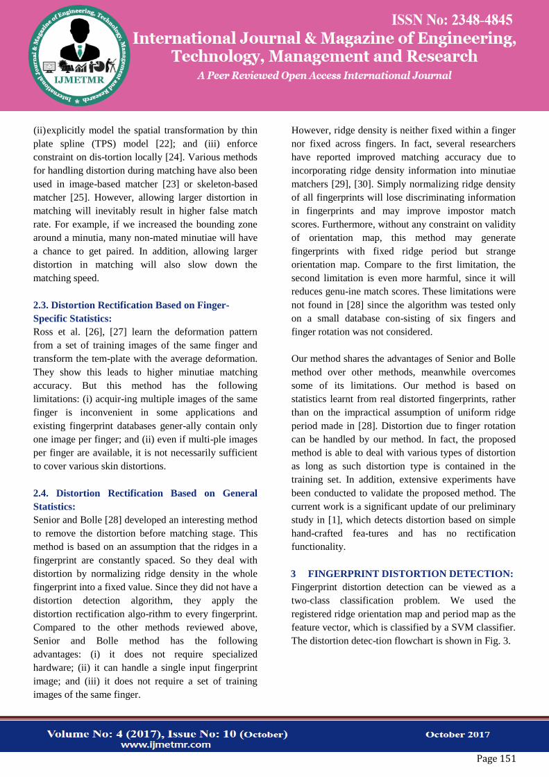
Fig. 3. Flowchart of fingerprint distortion
detection.
Oi represents ridge orientation at the ith sampling grid
of registered orientation map, while Pj rep-resents
ridge period at the jth sampling grid of registered
period map. l1 and l2 represent the number of sampling
points in registered orientation map and registered
period map, respectively. compared. For the most
widely used minutiae-based finger-print matching
method, the following three types of strate-gies have
been adopted to handle distortion: (i) assume a global
rigid transformation and use a tolerant box of fixed
size [20] or adaptive size [21] to compensate for
distortion;
Page 151
(ii) explicitly model the spatial transformation by thin
plate spline (TPS) model [22]; and (iii) enforce
constraint on dis-tortion locally [24]. Various methods
for handling distortion during matching have also been
used in image-based matcher [23] or skeleton-based
matcher [25]. However, allowing larger distortion in
matching will inevitably result in higher false match
rate. For example, if we increased the bounding zone
around a minutia, many non-mated minutiae will have
a chance to get paired. In addition, allowing larger
distortion in matching will also slow down the
matching speed.
2.3. Distortion Rectification Based on Finger-
Specific Statistics:
Ross et al. [26], [27] learn the deformation pattern
from a set of training images of the same finger and
transform the tem-plate with the average deformation.
They show this leads to higher minutiae matching
accuracy. But this method has the following
limitations: (i) acquir-ing multiple images of the same
finger is inconvenient in some applications and
existing fingerprint databases gener-ally contain only
one image per finger; and (ii) even if multi-ple images
per finger are available, it is not necessarily sufficient
to cover various skin distortions.
2.4. Distortion Rectification Based on General
Statistics:
Senior and Bolle [28] developed an interesting method
to remove the distortion before matching stage. This
method is based on an assumption that the ridges in a
fingerprint are constantly spaced. So they deal with
distortion by normalizing ridge density in the whole
fingerprint into a fixed value. Since they did not have a
distortion detection algorithm, they apply the
distortion rectification algo-rithm to every fingerprint.
Compared to the other methods reviewed above,
Senior and Bolle method has the following
advantages: (i) it does not require specialized
hardware; (ii) it can handle a single input fingerprint
image; and (iii) it does not require a set of training
images of the same finger.
However, ridge density is neither fixed within a finger
nor fixed across fingers. In fact, several researchers
have reported improved matching accuracy due to
incorporating ridge density information into minutiae
matchers [29], [30]. Simply normalizing ridge density
of all fingerprints will lose discriminating information
in fingerprints and may improve impostor match
scores. Furthermore, without any constraint on validity
of orientation map, this method may generate
fingerprints with fixed ridge period but strange
orientation map. Compare to the first limitation, the
second limitation is even more harmful, since it will
reduces genu-ine match scores. These limitations were
not found in [28] since the algorithm was tested only
on a small database con-sisting of six fingers and
finger rotation was not considered.
Our method shares the advantages of Senior and Bolle
method over other methods, meanwhile overcomes
some of its limitations. Our method is based on
statistics learnt from real distorted fingerprints, rather
than on the impractical assumption of uniform ridge
period made in [28]. Distortion due to finger rotation
can be handled by our method. In fact, the proposed
method is able to deal with various types of distortion
as long as such distortion type is contained in the
training set. In addition, extensive experiments have
been conducted to validate the proposed method. The
current work is a significant update of our preliminary
study in [1], which detects distortion based on simple
hand-crafted fea-tures and has no rectification
functionality.
3 FINGERPRINT DISTORTION DETECTION:
Fingerprint distortion detection can be viewed as a
two-class classification problem. We used the
registered ridge orientation map and period map as the
feature vector, which is classified by a SVM classifier.
The distortion detec-tion flowchart is shown in Fig. 3.
Page 152
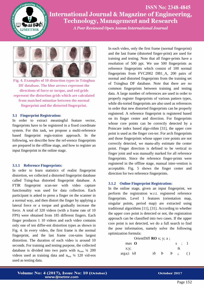
Fig. 4. Examples of 10 distortion types in Tsinghua
DF database. The blue arrows represent the
directions of force or torque, and red grids
represent the distortion grids which are calculated
from matched minutiae between the normal
fingerprint and the distorted fingerprint.
3.1 Fingerprint Registration:
In order to extract meaningful feature vector,
fingerprints have to be registered in a fixed coordinate
system. For this task, we propose a multi-reference
based fingerprint regis-tration approach. In the
following, we describe how the ref-erence fingerprints
are prepared in the offline stage, and how to register an
input fingerprint in the online stage.
3.1.1 Reference Fingerprints:
In order to learn statistics of realist fingerprint
distortion, we collected a distorted fingerprint database
called Tsing-hua distorted fingerprint database. A
FTIR fingerprint scan-ner with video capture
functionality was used for data collection. Each
participant is asked to press a finger on the scanner in
a normal way, and then distort the finger by applying a
lateral force or a torque and gradually increase the
force. A total of 320 videos (with a frame rate of 10
FPS) were obtained from 185 different fingers. Each
finger produces 1 10 videos and each video contains
only one of ten differ-ent distortion types as shown in
Fig. 4. In every video, the first frame is the normal
fingerprint, and the last frame con-tains largest
distortion. The duration of each video is around 10
seconds. For training and testing purpose, the collected
database is divided into two parts with ntrain ¼ 200
videos used as training data and ntest ¼ 120 vid-eos
used as testing data.
In each video, only the first frame (normal fingerprint)
and the last frame (distorted finger-print) are used for
training and testing. Note that all finger-prints have a
resolution of 500 ppi. We use 500 fingerprints as
reference fingerprints which consist of 100 normal
fingerprints from FVC2002 DB1_A, 200 pairs of
normal and distorted fingerprints from the training set
of Tsinghua DF database. Note that there are no
common fingerprints between training and testing
data. A large number of references are used in order to
properly register fingerprints of various pattern types,
while dis-torted fingerprints are also used as references
in order that new distorted fingerprints can be properly
registered. A reference fingerprint is registered based
on its finger center and direction. For fingerprints
whose core points can be correctly detected by a
Poincare index based algo-rithm [31], the upper core
point is used as the finger cen-ter. For arch fingerprints
and those fingerprints whose upper core points are not
correctly detected, we manu-ally estimate the center
point. Finger direction is defined to be vertical to
finger joint and was manually marked for all reference
fingerprints. Since the reference finger-prints were
registered in the offline stage, manual inter-vention is
acceptable. Fig. 5 shows the finger center and
direction for two reference fingerprints.
3.1.2 Online Fingerprint Registration:
In the online stage, given an input fingerprint, we
perform the registration w.r.t. registered reference
fingerprints. Level 1 features (orientation map,
singular points, period map) are extracted using
traditional algorithms [11], [31]. According to whether
the upper core point is detected or not, the registration
approach can be classified into two cases. If the upper
core point is not detected, we do a full search to find
the pose information, namely solve the following
optimization formula:
arg
max
k
OrientDiff RO x; y; a ;
O
Þ
u
tk
0
; 1
x;y;
a;i ð ið Þ ( )
Page 153
where x and y denote the translation parameters, a
denotes the rotation parameter, i denotes the
corresponding refer-ence fingerprint ID, O is the
orientation map of the input fingerprint, ROi denotes
the orientation map of the ith refer-ence fingerprint,
function OrientDiffðÞ computes the differ-ence of two
orientation maps at each location, k k0 counts the
number of nonzero elements, and ut is the threshold,
which is empirically set as 10 degrees. Note that the
ridge orientation map is defined on blocks of 16 16
pixels.
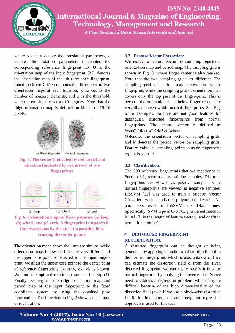
Fig. 5. The center (indicated by red circle) and
direction (indicated by red arrow) of two
fingerprints.
Fig. 6. Orientation maps of three patterns: (a) loop,
(b) whorl, and (c) arch. A fingerprint is separated
into tworegions by the gre en separating lines
crossing the center points.
The orientation maps above the lines are similar, while
orientation maps below the lines are very different. If
the upper core point is detected in the input finger-
print, we align the upper core point to the center point
of reference fingerprints. Namely, ðx; yÞ is known.
We find the optimal rotation parameter for Eq. (1).
Finally, we register the ridge orientation map and
period map of the input fingerprint to the fixed
coordinate system by using the obtained pose
information. The flowchart in Fig. 3 shows an example
of registration.
3.2 Feature Vector Extraction:
We extract a feature vector by sampling registered
orienta-tion map and period map. The sampling grid is
shown in Fig. 3, where finger center is also marked.
Note that the two sampling grids are different. The
sampling grid of period map covers the whole
fingerprint, while the sampling grid of orientation map
covers only the top part of the finger-print. This is
because the orientation maps below finger cen-ter are
very diverse even within normal fingerprints. See Fig.
6 for examples. So they are not good features for
distinguish distorted fingerprints from normal
fingerprints. The feature vector is defined as
½sinð2OÞ cosð2OÞP &, where
O denotes the orientation vector on sampling grids,
and P denotes the period vector on sampling grids.
Feature value at sampling points outside fingerprint
region is set as 0.
3.3 Classification:
The 500 reference fingerprints that we mentioned in
Section 3.1, were used as training samples. Distorted
fingerprints are viewed as positive samples while
normal fingerprints are viewed as negative samples.
LibSVM [32] was used to train a Support Vector
Classifier with quadratic polynomial kernel. All
parameters used in LibSVM are default ones.
Specifically, SVM type is C-SVC, g in kernel function
is 1=L (L is the length of feature vector), and coef0 in
kernel function is 0.
4 DISTORTED FINGERPRINT
RECTIFICATION:
A distorted fingerprint can be thought of being
generated by applying an unknown distortion field d to
the normal fin-gerprint, which is also unknown. If we
can estimate the dis-tortion field d from the given
distorted fingerprint, we can easily rectify it into the
normal fingerprint by applying the inverse of d. So we
need to address a regression problem, which is quite
difficult because of the high dimensionality of the
distortion field (even if we use a block-wise distortion
field). In this paper, a nearest neighbor regression
approach is used for this task.
Page 154
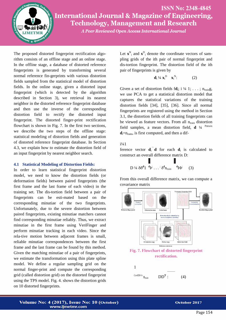
The proposed distorted fingerprint rectification algo-
rithm consists of an offline stage and an online stage.
In the offline stage, a database of distorted reference
fingerprints is generated by transforming several
normal reference fin-gerprints with various distortion
fields sampled from the statistical model of distortion
fields. In the online stage, given a distorted input
fingerprint (which is detected by the algorithm
described in Section 3), we retrieval its nearest
neighbor in the distorted reference fingerprint database
and then use the inverse of the corresponding
distortion field to rectify the distorted input
fingerprint. The distorted finger-print rectification
flowchart is shown in Fig. 7. In the first two sections,
we describe the two steps of the offline stage:
statistical modeling of distortion fields and generation
of distorted reference fingerprint database. In Section
4.3, we explain how to estimate the distortion field of
an input fingerprint by nearest neighbor search.
4.1 Statistical Modeling of Distortion Fields:
In order to learn statistical fingerprint distortion
model, we need to know the distortion fields (or
deformation fields) between paired fingerprints (the
first frame and the last frame of each video) in the
training set. The dis-tortion field between a pair of
fingerprints can be esti-mated based on the
corresponding minutiae of the two fingerprints.
Unfortunately, due to the severe distortion between
paired fingerprints, existing minutiae matchers cannot
find corresponding minutiae reliably. Thus, we extract
minutiae in the first frame using VeriFinger and
perform minutiae tracking in each video. Since the
rela-tive motion between adjacent frames is small,
reliable minutiae correspondences between the first
frame and the last frame can be found by this method.
Given the matching minutiae of a pair of fingerprints,
we estimate the transformation using thin plate spline
model. We define a regular sampling grid on the
normal finger-print and compute the corresponding
grid (called distortion grid) on the distorted fingerprint
using the TPS model. Fig. 4. shows the distortion grids
on 10 distorted fingerprints.
Let xN
i and xD
i denote the coordinate vectors of sam-
pling grids of the ith pair of normal fingerprint and
dis-tortion fingerprint. The distortion field of the ith
pair of fingerprints is given by
di ¼ xiD xi
N: (2)
Given a set of distortion fields fdi; i ¼ 1; . . . ; ntraing,
we use PCA to get a statistical distortion model that
captures the statistical variations of the training
distortion fields [34], [35], [36]. Since all normal
fingerprints are registered using the method in Section
3.1, the distortion fields of all training fingerprints can
be viewed as feature vectors. From all ntrain distortion
field samples, a mean distortion field, d ¼ Pntrain
di=ntrain, is first computed, and then a dif-
i¼1
ference vector di d for each di is calculated to
construct an overall difference matrix D:
D ¼ ððd1
dÞ
; . . .
; ð
dntrain
dÞÞ
: (3)
From this overall difference matrix, we can compute a
covariance matrix
Fig. 7. Flowchart of distorted fingerprint
rectification.
1
DDT :
CovðDÞ ¼ ntrain (4)
Page 155
Next, we calculate the eigenvectors feig and
eigenvalues f ig (sorted in decreasing order) of this
covariance matrix. The eigenvalues reflect the energy
distribution of the train-ing distortion fields among
eigenvectors, and the eigenvec-tors with the largest
eigenvalues generally cover the majority of the energy
within the training distortion fields. Therefore, a small
number of eigenvectors, serving as basis functions, can
well capture the distribution of training dis-tortion
fields. By using this distortion model, a new distor-
tion field d can be approximated as
t
d þ X i
pffiffi
ffiffi
ffii i (5)
d c e ;
i¼1
where fcig are the coefficients on the respective
eigenvec-tors, and t is the number of selected
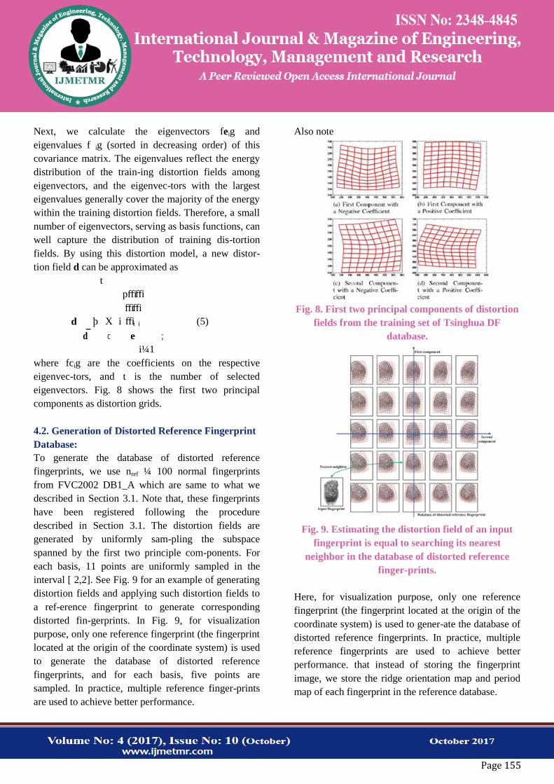
eigenvectors. Fig. 8 shows the first two principal
components as distortion grids.
4.2. Generation of Distorted Reference Fingerprint
Database:
To generate the database of distorted reference
fingerprints, we use nref ¼ 100 normal fingerprints
from FVC2002 DB1_A which are same to what we
described in Section 3.1. Note that, these fingerprints
have been registered following the procedure
described in Section 3.1. The distortion fields are
generated by uniformly sam-pling the subspace
spanned by the first two principle com-ponents. For
each basis, 11 points are uniformly sampled in the
interval [ 2,2]. See Fig. 9 for an example of generating
distortion fields and applying such distortion fields to
a ref-erence fingerprint to generate corresponding
distorted fin-gerprints. In Fig. 9, for visualization
purpose, only one reference fingerprint (the fingerprint
located at the origin of the coordinate system) is used
to generate the database of distorted reference
fingerprints, and for each basis, five points are
sampled. In practice, multiple reference finger-prints
are used to achieve better performance.
Also note
Fig. 8. First two principal components of distortion
fields from the training set of Tsinghua DF
database.
Fig. 9. Estimating the distortion field of an input
fingerprint is equal to searching its nearest
neighbor in the database of distorted reference
finger-prints.
Here, for visualization purpose, only one reference
fingerprint (the fingerprint located at the origin of the
coordinate system) is used to gener-ate the database of
distorted reference fingerprints. In practice, multiple
reference fingerprints are used to achieve better
performance. that instead of storing the fingerprint
image, we store the ridge orientation map and period
map of each fingerprint in the reference database.
Page 156
4.3. Distortion Field Estimation by Nearest
Neighbor Search:
Distortion field estimation is equal to finding the
nearest neighbor among all distorted reference
fingerprints as shown in Fig. 9. The similarity is
measured based on level 1 features of fingerprint,
namely ridge orientation map and period map. We
conjecture that distortion detection and rec-tification
of human experts also relies on these features instead
of minutiae. The similarity computation method is
different depending on whether the upper core point
can be detected in the input fingerprint. If the upper
core point is detected, we translate the input
fingerprint by aligning the upper core point to center
point. Then we do a full search of u in the interval ½
30 ; 30 & for the maximum similarity. For a specific u,
the similarity between two fingerprints is computed as
follows:
s
¼
s1O þ s2
O w1
Os1
O
þ
w2Os2
O
þ
s1P þ s2
P w1
Ps1
P
þ
w2Ps2
P ; (6)
m m
where m denotes the number of blocks in the
overlapping area, sO
1 and sO
2 denote the number of
blocks with similar orientation above and below the
center point, sP
1 and sP
2 denote the number of blocks
with similar period above and below the center point,
and the four weights wO
1, wO
2, wP
1 , wP
2 , are
empirically set as 1, 0.5, 1, 1.5, respectively.
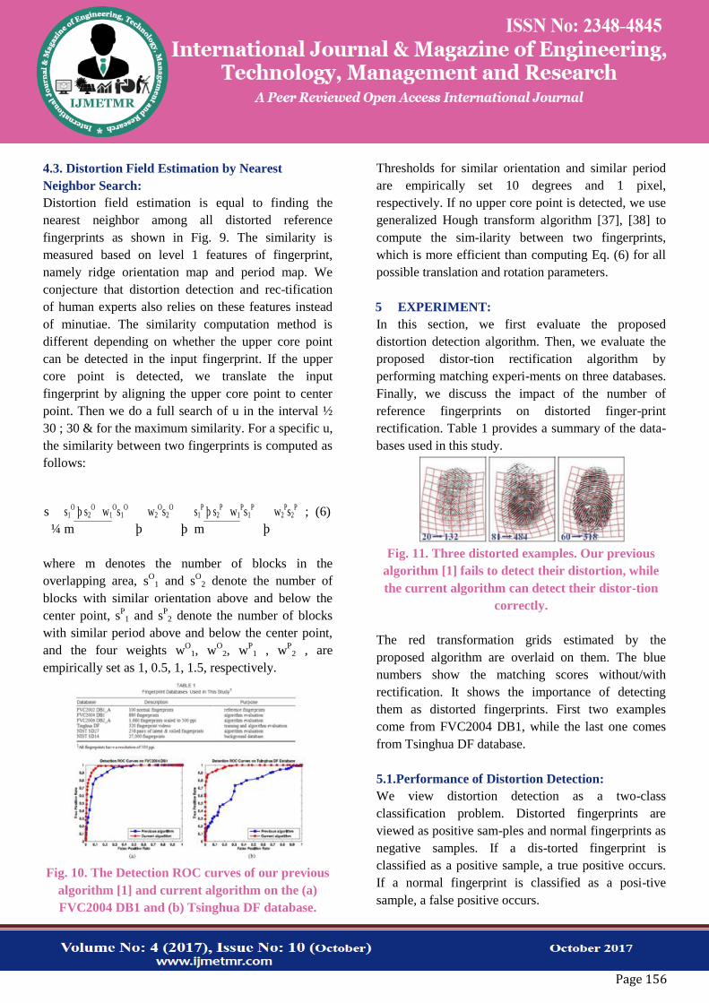
Fig. 10. The Detection ROC curves of our previous
algorithm [1] and current algorithm on the (a)
FVC2004 DB1 and (b) Tsinghua DF database.
Thresholds for similar orientation and similar period
are empirically set 10 degrees and 1 pixel,
respectively. If no upper core point is detected, we use
generalized Hough transform algorithm [37], [38] to
compute the sim-ilarity between two fingerprints,
which is more efficient than computing Eq. (6) for all
possible translation and rotation parameters.
5 EXPERIMENT:
In this section, we first evaluate the proposed
distortion detection algorithm. Then, we evaluate the
proposed distor-tion rectification algorithm by
performing matching experi-ments on three databases.
Finally, we discuss the impact of the number of
reference fingerprints on distorted finger-print
rectification. Table 1 provides a summary of the data-
bases used in this study.
Fig. 11. Three distorted examples. Our previous
algorithm [1] fails to detect their distortion, while
the current algorithm can detect their distor-tion
correctly.
The red transformation grids estimated by the
proposed algorithm are overlaid on them. The blue
numbers show the matching scores without/with
rectification. It shows the importance of detecting
them as distorted fingerprints. First two examples
come from FVC2004 DB1, while the last one comes
from Tsinghua DF database.
5.1.Performance of Distortion Detection:
We view distortion detection as a two-class
classification problem. Distorted fingerprints are
viewed as positive sam-ples and normal fingerprints as
negative samples. If a dis-torted fingerprint is
classified as a positive sample, a true positive occurs.
If a normal fingerprint is classified as a posi-tive
sample, a false positive occurs.
Page 157
By changing the deci-sion threshold, we can obtain the
receiver operating characteristic (ROC) curve. Fig. 10
shows the ROC curves of the proposed algorithm and
our previous algorithm [1] on FVC2004 DB1 and the
test set of Tsinghua DF database. The test set of
Tsinghua DF database contains 120 pairs of dis-torted
and normal fingerprints. FVC2004 DB1 contains.
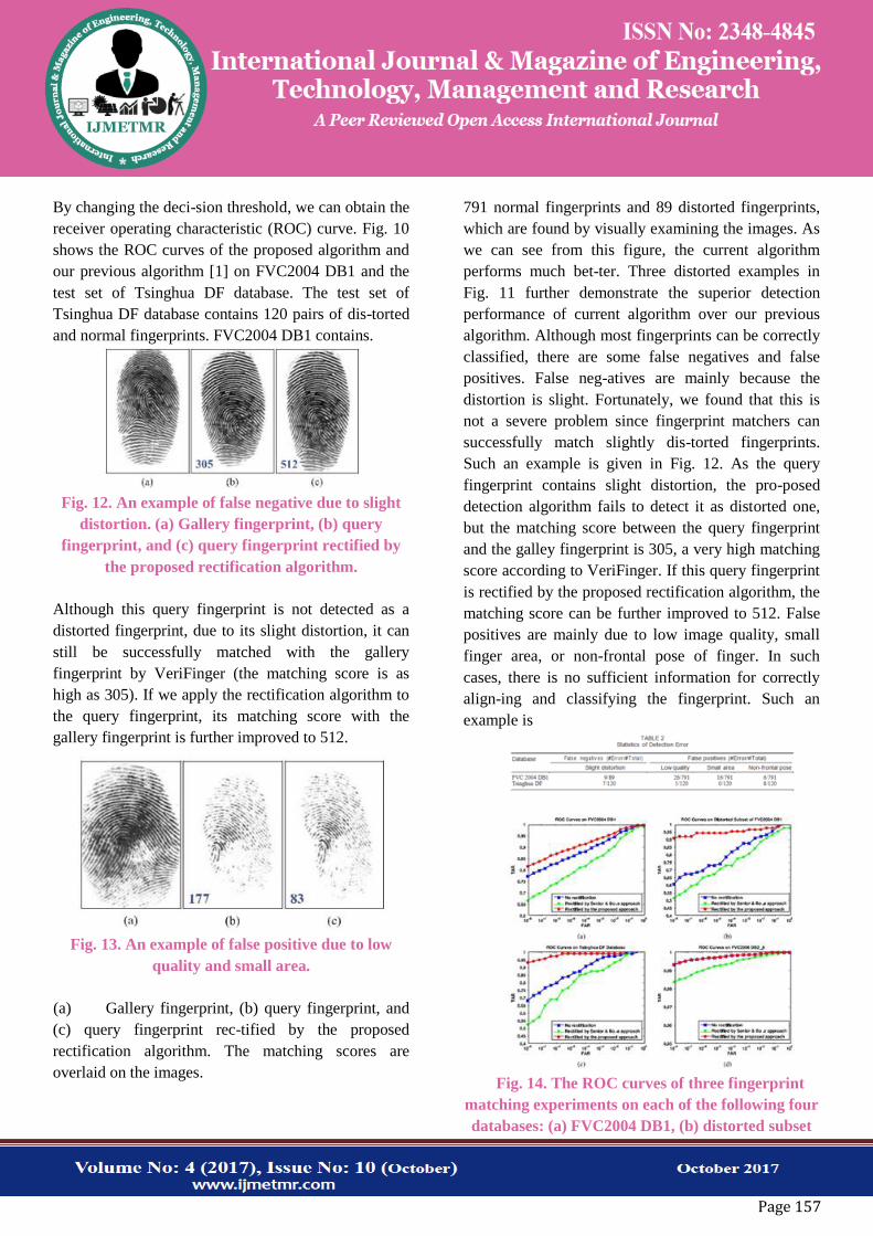
Fig. 12. An example of false negative due to slight
distortion. (a) Gallery fingerprint, (b) query
fingerprint, and (c) query fingerprint rectified by
the proposed rectification algorithm.
Although this query fingerprint is not detected as a
distorted fingerprint, due to its slight distortion, it can
still be successfully matched with the gallery
fingerprint by VeriFinger (the matching score is as
high as 305). If we apply the rectification algorithm to
the query fingerprint, its matching score with the
gallery fingerprint is further improved to 512.
Fig. 13. An example of false positive due to low
quality and small area.
(a) Gallery fingerprint, (b) query fingerprint, and
(c) query fingerprint rec-tified by the proposed
rectification algorithm. The matching scores are
overlaid on the images.
791 normal fingerprints and 89 distorted fingerprints,
which are found by visually examining the images. As
we can see from this figure, the current algorithm
performs much bet-ter. Three distorted examples in
Fig. 11 further demonstrate the superior detection
performance of current algorithm over our previous
algorithm. Although most fingerprints can be correctly
classified, there are some false negatives and false
positives. False neg-atives are mainly because the
distortion is slight. Fortunately, we found that this is
not a severe problem since fingerprint matchers can
successfully match slightly dis-torted fingerprints.
Such an example is given in Fig. 12. As the query
fingerprint contains slight distortion, the pro-posed
detection algorithm fails to detect it as distorted one,
but the matching score between the query fingerprint
and the galley fingerprint is 305, a very high matching
score according to VeriFinger. If this query fingerprint
is rectified by the proposed rectification algorithm, the
matching score can be further improved to 512. False
positives are mainly due to low image quality, small
finger area, or non-frontal pose of finger. In such
cases, there is no sufficient information for correctly
align-ing and classifying the fingerprint. Such an
example is
Fig. 14. The ROC curves of three fingerprint
matching experiments on each of the following four
databases: (a) FVC2004 DB1, (b) distorted subset
Page 158
of FVC2004 DB1, (c) Tsinghua DF database, and
(d) FVC2006 DB2_A.
The input images to VeriFinger in three matching
experiments are original fin-gerprints (no rectification
is performed), fingerprints rectified by Senior and
Bolle approach [28], and fingerprints rectified by the
proposed approach, respectively.
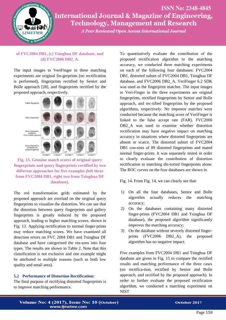
Fig. 15. Genuine match scores of original query
fingerprints and query fingerprints rectified by two
different approaches for five examples (left three
from FVC2004 DB1, right two from Tsinghua DF
database).
The red transformation grids estimated by the
proposed approach are overlaid on the original query
fingerprints to visualize the distortion. We can see that
the distortion between query fingerprints and gallery
fingerprints is greatly reduced by the proposed
approach, leading to higher matching scores. shown in
Fig. 13. Applying rectification to normal finger-prints
may reduce matching scores. We have examined all
detection errors on FVC 2004 DB1 and Tsinghua DF
database and have categorized the rea-sons into four
types. The results are shown in Table 2. Note that this
classification is not exclusive and one example might
be attributed to multiple reasons (such as both low
quality and small area).
5.2 Performance of Distortion Rectification:
The final purpose of rectifying distorted fingerprints is
to improve matching performance.
To quantitatively evaluate the contribution of the
proposed rectification algorithm to the matching
accuracy, we conducted three matching experiments
on each of the following four databases: FVC2004
DB1, distorted subset of FVC2004 DB1, Tsinghua DF
database, and FVC2006 DB2_A. VeriFinger 6.2 SDK
was used as the fingerprint matcher. The input images
to Veri-Finger in the three experiments are original
fingerprints, rectified fingerprints by Senior and Bolle
approach, and rec-tified fingerprints by the proposed
algorithms, respectively. No impostor matches were
conducted because the matching score of VeriFinger is
linked to the false accept rate (FAR). FVC2006
DB2_A was used to examine whether distortion
rectification may have negative impact on matching
accuracy in situations where distorted fingerprints are
absent or scarce. The distorted subset of FVC2004
DB1 con-sists of 89 distorted fingerprints and mated
normal finger-prints. It was separately tested in order
to clearly evaluate the contribution of distortion
rectification to matching dis-torted fingerprints alone.
The ROC curves on the four databases are shown in
Fig. 14. From Fig. 14, we can clearly see that:
1) On all the four databases, Senior and Bolle
algorithm actually reduces the matching
accuracy;
2) On the databases containing many distorted
finger-prints (FVC2004 DB1 and Tsinghua DF
database), the proposed algorithm significantly
improves the matching accuracy;
3) On the database without severely distorted finger-
prints (FVC2006 DB2_A), the proposed
algorithm has no negative impact.
Five examples from FVC2004 DB1 and Tsinghua DF
database are given in Fig. 15 to compare the rectified
results and matching performance of the three cases
(no rectifica-tion, rectified by Senior and Bolle
approach, and rectified by the proposed approach). In
order to further evaluate the proposed rectification
algorithm, we conducted a matching experiment on
NIST
Page 159
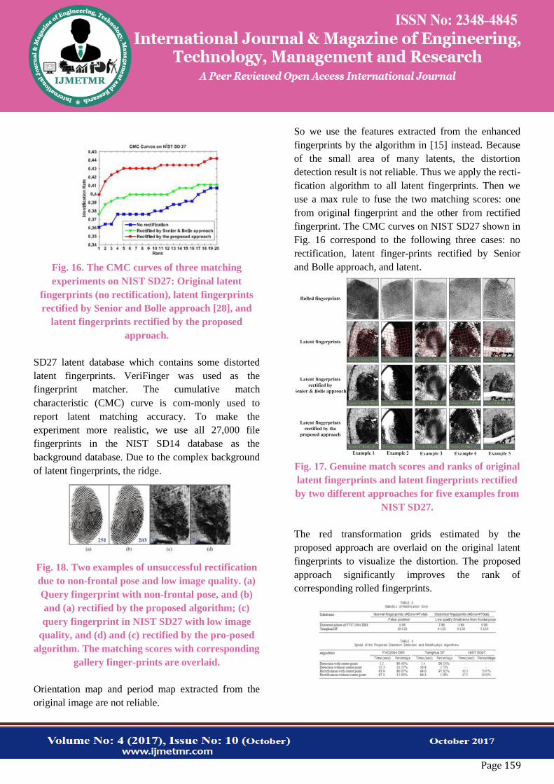
Fig. 16. The CMC curves of three matching
experiments on NIST SD27: Original latent
fingerprints (no rectification), latent fingerprints
rectified by Senior and Bolle approach [28], and
latent fingerprints rectified by the proposed
approach.
SD27 latent database which contains some distorted
latent fingerprints. VeriFinger was used as the
fingerprint matcher. The cumulative match
characteristic (CMC) curve is com-monly used to
report latent matching accuracy. To make the
experiment more realistic, we use all 27,000 file
fingerprints in the NIST SD14 database as the
background database. Due to the complex background
of latent fingerprints, the ridge.
Fig. 18. Two examples of unsuccessful rectification
due to non-frontal pose and low image quality. (a)
Query fingerprint with non-frontal pose, and (b)
and (a) rectified by the proposed algorithm; (c)
query fingerprint in NIST SD27 with low image
quality, and (d) and (c) rectified by the pro-posed
algorithm. The matching scores with corresponding
gallery finger-prints are overlaid.
Orientation map and period map extracted from the
original image are not reliable.
So we use the features extracted from the enhanced
fingerprints by the algorithm in [15] instead. Because
of the small area of many latents, the distortion
detection result is not reliable. Thus we apply the recti-
fication algorithm to all latent fingerprints. Then we
use a max rule to fuse the two matching scores: one
from original fingerprint and the other from rectified
fingerprint. The CMC curves on NIST SD27 shown in
Fig. 16 correspond to the following three cases: no
rectification, latent finger-prints rectified by Senior
and Bolle approach, and latent.
Fig. 17. Genuine match scores and ranks of original
latent fingerprints and latent fingerprints rectified
by two different approaches for five examples from
NIST SD27.
The red transformation grids estimated by the
proposed approach are overlaid on the original latent
fingerprints to visualize the distortion. The proposed
approach significantly improves the rank of
corresponding rolled fingerprints.
Page 160
Fingerprints rectified by the proposed approach. From
Fig. 16, we can see that both rectification algorithms
can improve the recognition rate and the proposed
algorithm performs better. Senior and Bolle approach
also helps improve matching accuracy here because of
the max fusion rule. Five examples from NIST SD27
are given in Fig. 17 to compare the rectified results by
two algorithms. Although the genuine match scores of
most distorted fin-gerprints are improved after
rectification, there are some examples whose matching
scores dropped after rectifica-tion. Unsuccessful
rectification can be classified into two categories: (1) a
normal fingerprint is incorrectly detected as a distorted
one and then undergoes the rectification process, and
(2) the rectification for a distorted fingerprint is incor-
rect. False positive of distortion detection is discussed
in Section 5.1. The main causes for unsuccessfully
rectified dis-torted fingerprints are non-frontal pose of
finger, low image quality and small area. In these
cases, there is no sufficient information for correctly
estimating the distortion field. Such two examples are
given in Fig. 18. We have examined all the matching
pairs with reduced scores on the distorted subset of
FVC 2004 DB1 and Tsing-hua DF database and has
categorized the cause of error. The results are shown
in Table 3. For a matching pair, if the nor-mal
fingerprint is a false positive, the cause is set as false
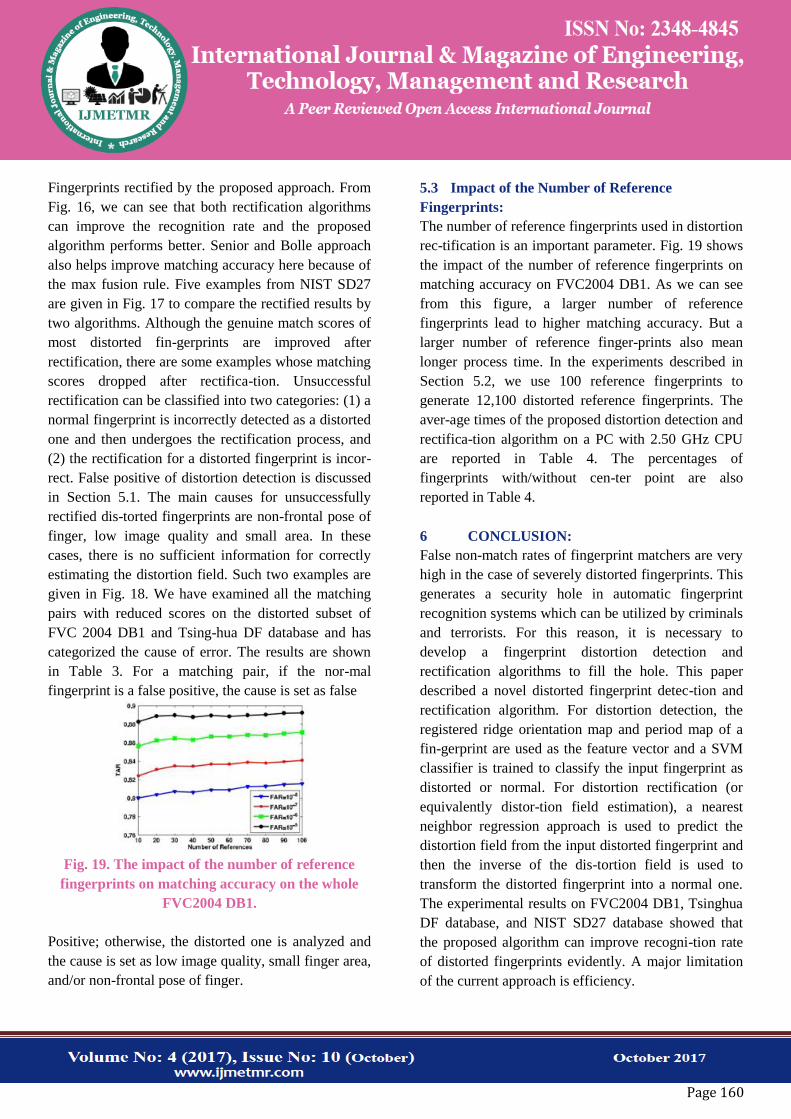
Fig. 19. The impact of the number of reference
fingerprints on matching accuracy on the whole
FVC2004 DB1.
Positive; otherwise, the distorted one is analyzed and
the cause is set as low image quality, small finger area,
and/or non-frontal pose of finger.
5.3 Impact of the Number of Reference
Fingerprints:
The number of reference fingerprints used in distortion
rec-tification is an important parameter. Fig. 19 shows
the impact of the number of reference fingerprints on
matching accuracy on FVC2004 DB1. As we can see
from this figure, a larger number of reference
fingerprints lead to higher matching accuracy. But a
larger number of reference finger-prints also mean
longer process time. In the experiments described in
Section 5.2, we use 100 reference fingerprints to
generate 12,100 distorted reference fingerprints. The
aver-age times of the proposed distortion detection and
rectifica-tion algorithm on a PC with 2.50 GHz CPU
are reported in Table 4. The percentages of
fingerprints with/without cen-ter point are also
reported in Table 4.
6 CONCLUSION:
False non-match rates of fingerprint matchers are very
high in the case of severely distorted fingerprints. This
generates a security hole in automatic fingerprint
recognition systems which can be utilized by criminals
and terrorists. For this reason, it is necessary to
develop a fingerprint distortion detection and
rectification algorithms to fill the hole. This paper
described a novel distorted fingerprint detec-tion and
rectification algorithm. For distortion detection, the
registered ridge orientation map and period map of a
fin-gerprint are used as the feature vector and a SVM
classifier is trained to classify the input fingerprint as
distorted or normal. For distortion rectification (or
equivalently distor-tion field estimation), a nearest
neighbor regression approach is used to predict the
distortion field from the input distorted fingerprint and
then the inverse of the dis-tortion field is used to
transform the distorted fingerprint into a normal one.
The experimental results on FVC2004 DB1, Tsinghua
DF database, and NIST SD27 database showed that
the proposed algorithm can improve recogni-tion rate
of distorted fingerprints evidently. A major limitation
of the current approach is efficiency.
Page 161
Both detection and rectification steps can be
significantly speeded up if a robust and accurate
fingerprint registration algorithm can be developed.
Another limitation is that the current approach does
not support rolled fingerprints. It is difficult to collect
many rolled fingerprints with various dis-tortion types
and meanwhile obtain accurate distortion fields for
learning statistical distortion model. It is our ongo-ing
work to address the above limitations.
ACKNOWLEDGMENTS:
This work was supported by the National Natural
Science Foundation of China under Grants 61225008,
61373074, and 61020106004, the National Basic
Research Program of China under Grant
2014CB349304, the Ministry of Education of China
under Grant 20120002110033, and the Tsinghua Uni-
versity Initiative Scientific Research Program.
REFERENCES:
[1] X. Si, J. Feng, and J. Zhou, “Detecting fingerprint
distortion from a single image,” in Proc. IEEE Int.
Workshop Inf. Forensics Security, 2012, pp. 1–6.
[2] D. Maltoni, D. Maio, A. K. Jain, and S. Prabhakar,
Handbook of Fin-gerprint Recognition, 2nd ed. Berlin,
Germany: Springer-Verlag, 2009.
[3] FVC2006: The fourth international fingerprint
verification competi-tion. (2006). [Online]. Available:
http://bias.csr.unibo.it/fvc2006/
[4] V. N. Dvornychenko, and M. D. Garris, “Summary
of NIST latent fingerprint testing workshop,” Nat. Inst.
Standards Technol., Gai-thersburg, MD, USA, Tech.
Rep. NISTIR 7377, Nov. 2006.
[5]Neurotechnology Inc., VeriFinger. (2009). [Online].
Available: http://www.neurotechnology.com
[6] L. M. Wein and M. Baveja, “Using fingerprint
image quality to improve the identification
performance of the U.S. visitor and immigrant status
indicator technology program,” Proc. Nat. Acad. Sci.
USA, vol. 102, no. 21, pp. 7772–7775, 2005.
[7] S. Yoon, J. Feng, and A. K. Jain, “Altered
fingerprints: Analysis and detection,” IEEE Trans.
Pattern Anal. Mach. Intell., vol. 34, no. 3, pp. 451–
464, Mar. 2012.
[8] E. Tabassi, C. Wilson, and C. Watson, “Fingerprint
image qual-ity,” Nat. Inst. Standards Technol.,
Gaithersburg, MD, USA, Tech. Rep. NISTIR 7151,
Aug. 2004.
[9] F. Alonso-Fernandez, J. Fierrez-Aguilar, J. Ortega-
Garcia, J. Gon-zalez-Rodriguez, H. Fronthaler, K.
Kollreider, and J. Bigun,€ “A comparative study of
fingerprint image-quality estimation meth-ods,” IEEE
Trans. Inf. Forensics Security, vol. 2, no. 4, pp. 734–
743, Dec. 2007.
[10] J. Fierrez-Aguilar, Y. Chen, J. Ortega-Garcia, and
A. K. Jain, “Incorporating image quality in multi-
algorithm fingerprint ver-ification,” in Proc. Int. Conf.
Biometrics, 2006, pp. 213–220.
[11] L. Hong, Y. Wan, and A. K. Jain, “Fingerprint
image enhance-ment: Algorithm and performance
evaluation,” IEEE Trans. Pat-tern Anal. Mach. Intell.,
vol. 20, no. 8, pp. 777–789, Aug. 1998.
[12] S. Chikkerur, A. N. Cartwright, and V.
Govindaraju, “Fingerprint enhancement using STFT
analysis,” Pattern Recognit., vol. 40, no. 1, pp. 198–
211, 2007.
[13] F. Turroni, R. Cappelli, and D. Maltoni,
“Fingerprint enhancement using contextual iterative
filtering,” in Proc. Int. Conf. Biometrics, 2012, pp.
152–157.
[14] J. Feng, J. Zhou, and A. K. Jain, “Orientation
field estimation for latent fingerprint enhancement,”
IEEE Trans. Pattern Anal. Mach. Intell., vol. 35, no. 4,
pp. 925–940, Apr. 2013.

Page 162
[15] X. Yang, J. Feng, and J. Zhou, “Localized
dictionaries based orien-tation field estimation for
latent fingerprints,” IEEE Trans. Pattern Anal. Mach.
Intell., vol. 36, no. 5, pp. 955–969, May 2014.
[16] R. M. Bolle, R. S. Germain, R. L. Garwin, J. L.
Levine, S. U. Pan-kanti, N. K. Ratha, and M. A.
Schappert, “System and method for distortion control
in live-scan inkless fingerprint images,” U.S. Patent
No. 6 064 753, May 16, 2000.