Embed Size (px)
Citation preview
An End-System Approach to Mobility Management for 4GNetworks and its Application to Thin-Client Computing
Leo Patanapongpibula Glenford Mappb Andy Hoppera
[email protected] [email protected] [email protected] Technology Group, Computer Laboratory, University of Cambridge, UK
bSchool of Computer Science, Middlesex University, UK
This paper describes work centred around providing greater autonomy for mobile nodes toroam in Mobile IPv6 wireless networks based on a new handoff mechanism. This technique,called the Client-based Handoff, enables mobile nodes to roam in foreign wireless networkswithout having to be controlled by the network infrastructure. The mechanism incorporatesthree algorithms: a router advertisement cache, the invocation of TCP mechanisms andtechniques to handle subnetwork outages in order to reduce packet loss and handoff latency.An experimental Mobile IPv6 testbed was developed to evaluate the proposed mechanismand is described in this paper. The testbed supports both horizontal and vertical handoffs.Experimental results are also presented.The outcome of this approach was used to support mobile thin-client computing using aVirtual Network Computer (VNC) environment. Relevant experiments were carried out andthe results show a compelling improvement in throughput of up to 50% compared to a VNCenvironment without the supporting architecture.
I. Introduction
Mobile IP does not have a mechanism to managehandoffs in the same way as cellular networks suchas GSM. Conventional handoffs in GSM are mobile-assisted, but the decision to perform a handoff isnetwork-controlled. The network would carry out themeasurement of the mobile node’s signal strength and,if the mobile node is in a call, would prepare the con-text to be handed off to a nearby cell. When themobile node is in standby mode, the network keepstrack of the device through a paging mechanism. Be-ing able to control the mobile node’s movements andcalls, provides cellular infrastructures with an easiermethod to authenticate, authorise and account (AAA)for the mobile node’s network usage.
Mobile IP has been designed for IP networks –a free for all medium – where the management ofthe network is distributed, with end users having asmuch control over the traffic as do the core entitiesin the network. Due to the nature of IP networks andfor heterogeneity between different networking tech-nologies, it may not be practical for handoffs to benetwork-controlled in the same way as cellular net-works. To impose restrictions on mobility and charg-ing for network connections, an entity in the core net-work is necessary to authenticate, authorise and ac-count for a mobile node’s activity. Hence, the pric-ing and policy model for packet-switched IP networks
will be different to circuit-switched cellular networks.
Thus, there is a trade off between heterogeneity andthe IP network having to provide mobility manage-ment when considering the AAA aspect. The workpresented in this article takes a different approach tothe network-controlled model.
In a cellular network, mobile nodes wishing to roamaway from its home network would need the opera-tors to have prior peering agreements. A client havingcomplete control over which network it wishes to joineliminates the need for such roaming agreements. Theclient can independently obtain a security associationwith the network it wishes to join without dependingon its network operator having to acquire a peeringagreement. This approach can therefore be describedas client-based and is investigated in this paper.
This research project is mobility-centric in a widearea network environment; IPv6 is the natural basisfor supporting mobility and the next incremental up-grade for the Internet. There are other advantages inusing IPv6, but these are not within the scope of thisarticle. The solution to the mobility issue is also back-ward compatible, but requires IPv4 networks to haveMobile IP enabled.
The focus is on the struggle for dominance in thetelecommunication marketplace. Network operatorsand service providers are often monopolising the mar-ket causing the customers to have no control overwhich network they can use once they buy into a con-
Mobile Computing and Communications Review, Volume 1, Number 2 1
tract. This research project aims to free the customerfrom their commitment to a particular network bymaking changes solely in the client in order to allowthem to gain control over their own mobile network-ing needs, not those of the network operator. The out-come of this effort can prove to be beneficial both forthe customers and network operators. This is because,besides the customer having control over the mobil-ity management aspect, the network operator can fo-cus on providing better and more varied services tothe customer. In this project, a thin-client system waschosen as an example application which a network op-erator can use to attract more customers.
The Client-based Handoff Mechanism provides amobile device with an intelligent method to select thenetwork it wishes to join and manages seamless hand-off with Mobile IP.
In this paper, we first discuss suitable steps to-wards an end-system approach to handoff manage-ment in Section II. Then in Section III, we pro-vide an overview of the Client-based Handoff Mech-anism. Section IV describes our network testbed usedto study the feasibility of the handoff mechanism. Wethen describe experiments to evaluate the mechanismin Section V. In Section VI, an application of ourend system approach to mobility management is in-troduced and evaluated. The application is called theMobile VNC. Finally, we discuss some related workin Section VII, and conclude this paper with a sum-mary of important research findings and future workin Sections VIII and IX, respectively.
II. Handoff Management for Wire-less IPv6 Networks
There are a number of design issues to consider inestablishing a suitable end-system solution to hand-off management for use in a unified wireless IPv6 in-ternetwork. Mobile IPv6 is the IETF standard (RFC3775) for supporting mobility in IPv6 networks. Be-cause the protocol is a layer-3 solution to mobility,it has not been designed for any specific layer-1 orlayer-2 technologies. The protocol, however, has in-cluded a general explanation on how to interface withlower layer technologies. The handoff managementdesign must consider various handoff scenarios a mo-bile node could encounter while roaming in wirelessIPv6 networks. Active TCP sessions are also anotherfactor which affects the perceived user experience onthe overall handoff latency. Methods to optimise therecovery of TCP connections after a disruption causedby a handoff should also be considered. To be able
to solve these issues whilst taking an end-systems ap-proach, we should look at ways to optimise mecha-nisms already available in existing protocols.
II.A. Handoff Facilitators
A number of Mobile IP and Neighbour Discoveryprotocol (RFC2461) mechanisms are key to assist-ing a mobile node’s handoff from one point of at-tachment to another. The Mobile IP mechanism ismovement detection while the Neighbour Discoveryprotocol mechanisms are Router Discovery, AddressAutoconfiguration and Duplicate Address Detection.These mechanisms are discussed below.
II.A.1. Router Discovery
This mechanism is used to locate nearby routers andto determine network prefixes. The network prefixis important to address autoconfiguration (RFC2462),which is performed by hosts to configure their net-work interface with valid IP addresses to accessnearby network resources. A pair of ICMPv6 mes-sages are defined for Router Discovery:
• Router advertisement is periodically multicastby access routers to all IPv6 hosts. Each adver-tisement contains a limited life-time. If anotheradvertisement is received by the mobile nodewithin the life-time of an advertisement message,then the related access router is reachable. Other-wise, once the life-time expires, the access routeris assumed to be unreachable. At this point, themobile node commences searching for a new ac-cess router. The Neighbour Discovery protocolspecifies the interval of the advertisement to bebetween 3 to 10 seconds. However, Mobile IPv6recommends a more frequent interval of 0.03 to0.1 seconds. The movement detection (discussedbelow) can rely solely on router advertisements(i.e., Layer-3 trigger) for handoffs but has a tradeoff between the frequency of the router advertise-ment and the handoff latency. The router adver-tisement is necessary to acquire a care-of addressfor network connectivity on the new link.
• Router solicitation is multicast by IPv6 hosts toall IPv6 routers in the network in search of a newaccess router to join. If an access router is reach-able, the router responds with a router advertise-ment. Unlike router advertisements, router solic-itations are not sent periodically. This messageis normally used by a node whose IP address re-quires renewal. In the case of a mobile node, the
2 Mobile Computing and Communications Review, Volume 1, Number 2
sending of a router solicitation may be necessaryto immediately resume network connectivity ona new link. The handoff latency is largely depen-dent on the time of this movement detection andthe round-trip time between the mobile node andaccess router.
II.A.2. Duplicate address detection
Duplicate address detection is a method to determinewhether a mobile node’s address is valid. The proce-dure is an intrinsically secure method to rule out nodesthat implement IP address spoofing. Upon the receiptof a new binding update from the mobile node by thehome agent, all of the registered home and care-of ad-dresses are checked for any duplication. If this checkfails, the binding update is rejected and a binding ac-knowledgement is sent to the mobile node with theStatus field set to Duplicate Address Detection failed(134). This detection process can facilitate or pre-vent a successful handoff and influences the handofflatency.
II.A.3. Address Autoconfiguration
IPv6 defines two types of address autoconfigurationmechanism: stateful (also known as DHCPv6) andstateless. The latter is a straight forward approach fora host to form an IP address on its network interface.It uses locally available information and informationadvertised by routers. It is the best and fastest possiblemethod for the mobile node to form a new IP addresssince the information is piggybacked with the routeradvertisement.
II.A.4. Movement detection
Movement detection is a technique defined by MobileIP for mobile nodes to detect a move into a new net-work. A new access router can be discovered usinglayer-2 or layer-3 information. The Mobile IPv6 RFCsuggests a movement detection based on layer-2, butdoes not specify how to perform the detection. Thehandoff response, thus the latency, is dependent onlayer-2 and/or layer-3 triggers.
The Client-based Handoff Mechanism makes useof the existing IPv6 and Mobile IP functionalities de-scribed above. This empowers the mobile node withnetwork-independent mobility management. The mo-bile node can initiate and control handoffs without theneed to depend on specialised network entities in thecore network to support handoffs.
Due to the mobile node’s mobility independence,vertical handoffs in an overlay wireless network en-
vironment is made simple and practical. Since linklayer information is used as a determinate for hand-off, additional network interfaces on a mobile nodecan increase the choice of network link.
In the subsequent sections, we describe the Client-based Handoff Mechanism in detail. Our heteroge-neous Mobile IPv6 network testbed which was pur-posely set up to test our proposed mechanism will alsobe described.
III. Overview of the Client-basedHandoff Mechanism
There are two ways to provide a suitable handoffmechanism for mobile nodes. The first is to makemodifications or extensions to the entities in the net-work infrastructure. Routers or base stations can bechanged so that they will only send router advertise-ments to the mobile node when a handoff is necessaryas opposed to periodically sending router advertise-ments. However, this means the approximate loca-tion and signal strength of the mobile node need to becached in nearby routers or base stations. Additionalsignaling may be required in order to enable such asystem to operate correctly. Furthermore, changes torouters are difficult and disruptive in contrast to anend-system approach which is less intrusive. Modi-fications to the core network infrastructure has the ad-vantage of offering a complete mobility managementprotocol for the entire network to reduce handoff de-lays, but has the disadvantage of introducing greatercomplexity.
The second way is to make modifications or exten-sions on the client-side, i.e. the mobile node. In thiscase, it is the client that decides when a handoff is ap-propriate. This necessarily implies some loss of con-trol on the network domain’s side. The advantage ofthis, however, is its apparent simplicity and scalabil-ity, which are the reasons why the handoff mechanismdescribed in this section is based on this approach.
This section describes the mechanism in detail andhow it tackles the following issues:
1. Controlling and forcing handoffs
2. Determining the best link
3. Handing off at the appropriate time
4. Resuming active TCP connections
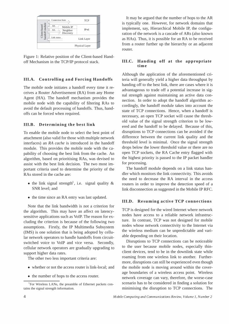
The Client-based Handoff Mechanism is illustratedin Figure 1 as a module in the TCP/IP protocol stack.
Mobile Computing and Communications Review, Volume 1, Number 2 3
Physical Layer
Link Layer
IPv6Mobile IP
TCP
Clie
nt-b
ased
hand
off m
odul
e
NeighborDiscovery
Connection State
Link status
RA
BA
Figure 1: Relative position of the Client-based Hand-off Mechanism in the TCP/IP protocol stack.
III.A. Controlling and Forcing Handoffs
The mobile node initiates a handoff every time it re-ceives a Router Advertisement (RA) from any HomeAgent (HA). The handoff mechanism provides themobile node with the capability of filtering RAs toavoid the default processing of handoffs. Thus, hand-offs can be forced when required.
III.B. Determining the best link
To enable the mobile node to select the best point ofattachment (also valid for those with multiple networkinterfaces) an RA cache is introduced in the handoffmodule. This provides the mobile node with the ca-pability of choosing the best link from the cache. Analgorithm, based on prioritising RAs, was devised toassist with the best link decision. The two most im-portant criteria used to determine the priority of theRAs stored in the cache are:
• the link signal strength1, i.e. signal quality &SNR level; and
• the time since an RA entry was last updated.
Note that the link bandwidth is not a criterion forthe algorithm. This may have an affect on latency-sensitive applications such as VoIP. The reason for ex-cluding the criterion is because of the following twoassumptions. Firstly, the IP Multimedia Subsystem(IMS) is one solution that is being adopted by cellu-lar network operators to handle handoffs from circuit-switched voice to VoIP and vice versa. Secondly,cellular network operators are gradually upgrading tosupport higher data rates.
The other two less important criteria are:
• whether or not the access router is link-local; and
• the number of hops to the access router.
1For Wireless LANs, the preamble of Ethernet packets con-tains the signal strength information.
It may be argued that the number of hops to the ARis typically one. However, for network domains thatimplement, say, Hierarchical Mobile IP, the configu-ration of the network is a cascade of ARs (also knownas HAs). Thus, it is possible for an RA to be receivedfrom a router further up the hierarchy or an adjacentrouter.
III.C. Handing off at the appropriatetime
Although the application of the aforementioned cri-teria will generally yield a higher data throughput byhanding off to the best link, there are cases where it isadvantageous to trade off a potential increase in sig-nal strength against maintaining an active data con-nection. In order to adopt the handoff algorithm ac-cordingly, the handoff module takes into account thestate of TCP connections. Hence, when a handoff isnecessary, an open TCP socket will cause the thresh-old value of the signal strength criterion to be low-ered and the handoff to be delayed. Because of this,disruptions to TCP connections can be avoided if thedifference between the current link quality and thethreshold level is minimal. Once the signal strengthdrops below the lower threshold value or there are noopen TCP sockets, the RA Cache entry flagged withthe highest priority is passed to the IP packet handlerfor processing.
The handoff module depends on a link status han-dler which monitors the link connectivity. This avoidsthe need to decrease the RA interval in the accessrouters in order to improve the detection speed of alink disconnection as suggested in the Mobile IP RFC.
III.D. Resuming active TCP connections
TCP is designed for the wired Internet where networknodes have access to a reliable network infrastruc-ture. In contrast, TCP was not designed for mobilenodes whose network connectivity to the Internet viathe wireless medium can be unpredictable and vari-able depending on their location.
Disruptions to TCP connections can be noticeableto the user because mobile nodes, especially thin-client devices, tend to be in the downlink state whileroaming from one wireless link to another. Further-more, disruptions can still be experienced even thoughthe mobile node is moving around within the cover-age boundaries of a wireless access point. Wirelessnetwork coverage can vary, therefore, the worse-casescenario has to be considered in finding a solution forminimising the disruption to TCP connections. The
4 Mobile Computing and Communications Review, Volume 1, Number 2
worst possible case scenarios are unanticipated hand-offs and intermittent link disconnections.
At a single packet drop, TCP can assume that thenetwork is congested causing the transmitter to throt-tle the transmission by decreasing the congestion win-dow to the minimum size. This works well for awired network, however, in a wireless network, thelink quality can vary especially when dealing withmoving computers. A drop in packet does not nec-essarily mean congestion in the network, but rather aweak link connectivity.
There are two approaches to enhance the user ex-perience of TCP applications for mobile computing.One approach is to modify or introduce a new TCPvariant. Another approach is to avoid any internalmodifications and provide a mechanism which can actas a catalyst to invoke existing TCP mechanisms. Thework in this article takes the second approach whereTCP mechanisms, such as fast retransmit, are utilisedto improve the mobile computing user experience.
Taking advantage of the functionalities provided byTCP is essential for the handoff mechanism to be fullyaware of activities in the higher layers of the protocolstack for handoff intelligence. Our handoff mecha-nism monitors the TCP connection states for all net-work connections including outgoing and incomingpacket queues, and triggers a TCP fast retransmit orTCP persist mode at the correspondent node. Whena handoff is imminent, the handoff mechanism low-ers the signal quality threshold to delay the event andbuffers the last TCP acknowledgement packet neces-sary for use after the handoff. The appropriate TCPmechanism is then invoked for the respective handoffscenarios discussed in Section IV.B.
III.E. Link Adaptation
There is the argument of different link speeds whenhanding off from, say, a faster network to a slowerone. In such an event, our mechanism can determinethe type of the new link based on the RAs in order tochoose the best action to resume an active TCP datatransfer. The technique to resume TCP transmissionwhen handing over between different link speeds ortype, i.e., a handoff between different domains or dif-ferent network technologies would be to trigger a TCPpersist mode at the sender. For handoffs between sub-nets where the link speed and type are equivalent, thetechnique for resuming TCP connections is to triggera TCP fast retransmit and fast recovery at the sender.These are simple solutions to link adaptation for TCPtraffic. However, other type of traffic such as UDP re-quire a different method of link adaptation. This issue
is beyond the scope of this paper. The discussion oflink adaptation is an active research topic and may beexplored as future work.
IV. Our Mobile IPv6 Testbed
With the collaboration of the University of CambridgeComputer Laboratory, our Mobile IPv6 testbed is ex-tended to support a connection to Vodafone’s GPRSnetwork. The combined Wireless LAN (WLAN) andGPRS testbed is illustrated in Figure 7. A number ofpublications [1, 2, 3] resulted from work carried outon the combined testbed. In this section, we describethe testbed and the handoff process in detail.
There are two key motivating factors for the col-laboration to setup the testbed. The first is to evalu-ate performance issues of Mobile IPv6 in a wirelessoverlay (heterogeneous) network environment. Thesecond factor is the need to develop enhancements,where necessary, for seamless handoffs between dif-ferent wireless networks.
A mobile node is configured with two network con-nections, one to our (DTG) WLAN testbed with anOrinoco WLAN PC card and the other to the GPRSnetwork via a serial point-to-point link to a GPRS mo-bile phone. For thorough testing purposes, the latestGPRS phones and cards from a number of manufac-turers are employed.
The base stations in the GPRS infrastructure aredirectly linked to the Serving GPRS Support Node(SGSN) which is then connected to a Gateway GPRSSupport Node (GGSN). The current operator’s con-figuration has the SGSN and GGSN co-located in asingle Combined GPRS Support Node (CGSN) [4].A virtual private network (VPN) connects the Labo-ratory network to Vodafone’s network backbone viaan IPSec tunnel over the Internet. A Remote Authen-tication Dial-In User Service (RADIUS, RFC2865)server, separate from the operator’s server, is provi-sioned to authenticate GPRS mobile users/terminalsand assign IP addresses.
Special arrangements with Vodafone and the twoUniversity of Cambridge departments - ComputerLaboratory and Engineering Department - enableGPRS and WLAN data traffic to be routed throughthe combined testbed. Routing has been configuredto force all GPRS and WLAN user data traffic go-ing to and from the mobile nodes to pass through aIPv4/IPv6 Linux router. This router, illustrated in Fig-ure 7, enables traffic monitoring.
The GPRS network does not support IPv6. Thismeans all IPv6 packets destined for a mobile node
Mobile Computing and Communications Review, Volume 1, Number 2 5
visiting the GPRS network had to be tunneled to themobile nodes as shown in Figure 7. The method tosupport IPv6 in the GPRS network is described in de-tail below. Note that all of the nodes in the testbed,including all correspondent nodes, support Mobile IPand route optimisation.
IV..1. IPv6 Data Communication in theGPRS network
The home agent of the mobile node is in the WLANpart of the testbed. When the mobile node switchesfrom its WLAN interface to its GPRS connection,a tunnel is automatically established between anIPv4/IPv6 edge router and the mobile node. Thisrouter is responsible for sending router advertisementsin the GPRS network. It is also reachable by the mo-bile node’s home network since it is part of the IPv6Internet. This means all binding updates from the mo-bile node in the GPRS network can be routed to thehome agent. Binding updates are tunneled from themobile node to the GPRS IPv4/IPv6 edge router andthen routed normally to the home agent.
When the mobile node wishes to set up a data con-nection to a correspondent node, provided that a bind-ing of the mobile node’s care-of address and homeaddress already exists at the home agent, a bindingupdate is first tunneled to the GPRS edge router androuted normally to the correspondent node. Follow-ing a successful binding update, packets destined forthe mobile node are routed to the GPRS edge routerwhere they are then encapsulated (RFC2473) and tun-neled to the mobile node.
The soft state tunnel set up to carry IPv6 traffic overthe IPv4 Internet is called a Simple Internet Transition(SIT) tunnel. As mentioned above, when the mobilenode is in the GPRS network, a SIT interface is ac-tivated on the IPv4/IPv6 router and the mobile node.However, the tunnel between the SIT interfaces can-not be established due to firewalls between the var-ious network domain. The GPRS network is underthe Computer Laboratory’s network domain adminis-tration and the IPv6 Internet (6BONE) is only acces-sible through the Engineering Department. As a re-sult, when the mobile node wishes to communicate toa correspondent node in the 6BONE, the encapsulatedIPv6 packets need to propagate through the ComputerLaboratory’s and Engineering Department’s firewalls.Thus, a “hole” has to be in place in each of the fire-walls to allow the flow of IPv6 packets which are en-capsulated in IPv4 packets.
IV.A. Types of Handoff
Handoffs are categorised into two groups: horizontaland vertical handoffs.
Horizontal handoff is the handoff between any twopoints of attachment of the same wireless networktechnology.
Vertical handoff is the handoff between any twodifferent wireless network technologies. There aretwo subsets for this type of handoff. The first is an up-ward handoff. This occurs when a mobile node moveshigher up in an overlay wireless network, e.g. from amicro-cell (WLAN) to a macro-cell (3G). The secondsubset is a downward handoff. This is when a mobilenode moves down in an overlay, e.g. from a macro-cell to a micro-cell.
IV.B. Handoff Scenarios
There are two situations where handoff can be initi-ated:
Scenario 1 - Discontinuous Handoffs: The currentmobile node’s point of attachment becomes out ofrange (e.g., beyond a WLAN coverage or a disconnec-tion from a LAN), preventing any data transmission orreception.
In these situations, the execution of a handoff isforced but without the knowledge of the next newpoint of attachment to which the mobile node can re-connect. Thus, this is called a discontinuous handoffsince the mobile node is unable to anticipate a newlink to the network. In this scenario, there is likelyto be severe packet loss because it is uncertain whenthe next network attachment will occur, hence to pre-vent this, it is better to use the TCP persist timer atthe correspondent node. The procedure is carried outin the following sequence. As described in SectionIII.D, prior to a disconnection from the network: thesignal strength threshold is lowered; TCP acknowl-edgements are sent advertising a zero window; andthe last TCP acknowledgement packet is buffered bythe handoff mechanism. Once the mobile node iswithin reach of a link, the sending of a Router So-licitation (RS) is forced to quickly acquire an RA.After the Mobile IP registration process finishes, thebuffered acknowledgement packet (non-zero window)is transmitted only once to the correspondent node inresponse to the previous zero window acknowledge-ment packet, hence, allowing the sender to resumethe TCP transmission. A discontinuous handoff couldalso happen unexpectedly. In such an unlikely event,it is not possible to minimise the handoff latency be-cause there is no time to trigger the TCP persist timer.
6 Mobile Computing and Communications Review, Volume 1, Number 2
However, the fast retransmit technique used for con-tinuous handoffs is applied in this situation withoutany performance degradation.
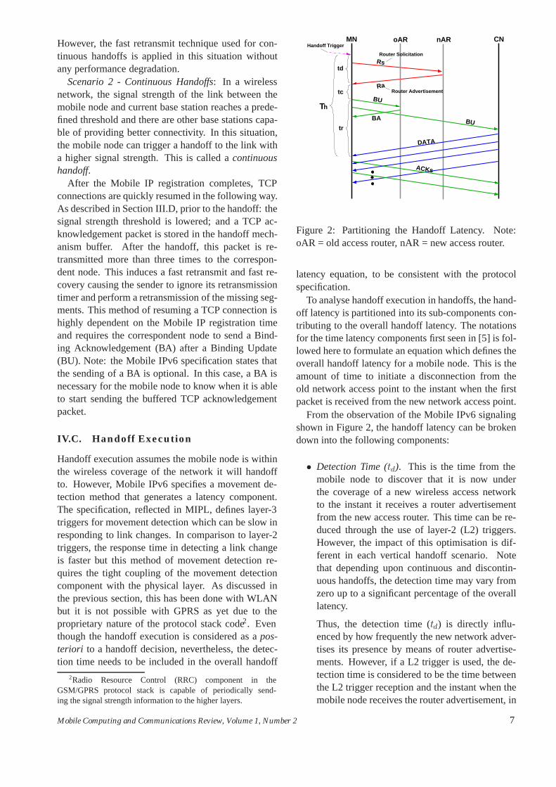
Scenario 2 - Continuous Handoffs: In a wirelessnetwork, the signal strength of the link between themobile node and current base station reaches a prede-fined threshold and there are other base stations capa-ble of providing better connectivity. In this situation,the mobile node can trigger a handoff to the link witha higher signal strength. This is called a continuoushandoff.
After the Mobile IP registration completes, TCPconnections are quickly resumed in the following way.As described in Section III.D, prior to the handoff: thesignal strength threshold is lowered; and a TCP ac-knowledgement packet is stored in the handoff mech-anism buffer. After the handoff, this packet is re-transmitted more than three times to the correspon-dent node. This induces a fast retransmit and fast re-covery causing the sender to ignore its retransmissiontimer and perform a retransmission of the missing seg-ments. This method of resuming a TCP connection ishighly dependent on the Mobile IP registration timeand requires the correspondent node to send a Bind-ing Acknowledgement (BA) after a Binding Update(BU). Note: the Mobile IPv6 specification states thatthe sending of a BA is optional. In this case, a BA isnecessary for the mobile node to know when it is ableto start sending the buffered TCP acknowledgementpacket.
IV.C. Handoff Execution
Handoff execution assumes the mobile node is withinthe wireless coverage of the network it will handoffto. However, Mobile IPv6 specifies a movement de-tection method that generates a latency component.The specification, reflected in MIPL, defines layer-3triggers for movement detection which can be slow inresponding to link changes. In comparison to layer-2triggers, the response time in detecting a link changeis faster but this method of movement detection re-quires the tight coupling of the movement detectioncomponent with the physical layer. As discussed inthe previous section, this has been done with WLANbut it is not possible with GPRS as yet due to theproprietary nature of the protocol stack code2. Eventhough the handoff execution is considered as a pos-teriori to a handoff decision, nevertheless, the detec-tion time needs to be included in the overall handoff
2Radio Resource Control (RRC) component in theGSM/GPRS protocol stack is capable of periodically send-ing the signal strength information to the higher layers.
Th
MN CNoAR nAR
td
tc
tr
Router Solicitation
Router Advertisement
Handoff Trigger
Ra
Rs
BU
ACKs
DATA
BU
BA
Figure 2: Partitioning the Handoff Latency. Note:oAR = old access router, nAR = new access router.
latency equation, to be consistent with the protocolspecification.
To analyse handoff execution in handoffs, the hand-off latency is partitioned into its sub-components con-tributing to the overall handoff latency. The notationsfor the time latency components first seen in [5] is fol-lowed here to formulate an equation which defines theoverall handoff latency for a mobile node. This is theamount of time to initiate a disconnection from theold network access point to the instant when the firstpacket is received from the new network access point.
From the observation of the Mobile IPv6 signalingshown in Figure 2, the handoff latency can be brokendown into the following components:
• Detection Time (td). This is the time from themobile node to discover that it is now underthe coverage of a new wireless access networkto the instant it receives a router advertisementfrom the new access router. This time can be re-duced through the use of layer-2 (L2) triggers.However, the impact of this optimisation is dif-ferent in each vertical handoff scenario. Notethat depending upon continuous and discontin-uous handoffs, the detection time may vary fromzero up to a significant percentage of the overalllatency.
Thus, the detection time (td) is directly influ-enced by how frequently the new network adver-tises its presence by means of router advertise-ments. However, if a L2 trigger is used, the de-tection time is considered to be the time betweenthe L2 trigger reception and the instant when themobile node receives the router advertisement, in
Mobile Computing and Communications Review, Volume 1, Number 2 7
response to the generated request sent from themobile node to the new access point followingthe reception of the L2 event. Note that in antici-pated handoffs the detection time is independentfrom the router advertisement frequency of thenew network.
• Address Configuration Time (tc). This is the la-tency encountered when a mobile node receivesa router advertisement and forms the new care-ofaddress, updates its binding cache and routing ta-ble and configures its interface with the new IPv6address. It is important to observe that this timeincludes L2 reconfiguration because forming thenew care-of address implies selecting the activeinterface [MAC address].
• Registration Time (tr). It is the time to regis-ter the new care-of address with the home agentand to update the correspondent nodes, performa Duplicate Address Detection if necessary andreceive the last binding acknowledgement (BA)packet either from correspondent nodes or homeagent (whichever arrives later). This is com-monly known as the Mobile IPv6 registrationprocess.
• Packet Forwarding Time (tf ). This is the timeafter the reception of the last binding acknowl-edgement from either the home agent or the cor-respondent node to the time the mobile node re-ceives the first data packet from the correspon-dent node. This component is insignificant, thusit is not illustrated in Figure 2.
The total handoff latency (Th) is therefore given by:
Th = td + tc + tr + tf (1)
The total latency is shown in Figure 2. Note thatthe parameters are constant and the magnitude of eachcomponent may vary significantly depending on thevertical handoff properties (upward, downward, con-tinuous and discontinuous). However, other compo-nents may be optimized in order to reduce the overalllatency, hence improving the mobile user experience.
For example, the coverage to the current accesspoint may be lost before the mobile node manages tohandoff to the new access point (occurs commonly inhigh mobility environments), thus a downward verti-cal handoff can still afford to delay a handoff decisionas the mobile node remains under coverage of the net-work higher up in the overlay. Note that a handoff de-cision for the case of upward vertical handoff cannot
be delayed, as coverage from networks lower downthe overlay (e.g. WLANs) can be lost before it fi-nally handoffs to networks higher up in the overlay.Hence not all vertical handoff decisions can be antic-ipated, but, rather, in some cases they can be delayedto achieve minimal latency.
V. Experiments
We divide the experiments into two categories. Firstly,we test the effectiveness of the Client-based HandoffMechanism in performing horizontal handoffs. Sec-ondly, we compare the handoff latency for horizontaland vertical handoffs with the Client-based HandoffMechanism disabled. It is not necessary to investigatethe improvement of the Client-based Handoff Mech-anism in the latter experiment. This is because theClient-based Handoff Mechanism is independent ofthe network medium, i.e. physical layer.
In both experiments, we measure the handoff la-tency based on a TCP file download to a mobile node.In addition, the testbed is set up to operate under thefollowing conditions:
• All access routers including the home agent areset to multicast router advertisements in accor-dance with the recommended values specified bythe Neighbour Discovery protocol (RFC2461).
• For all cases, a vertical handoff assumes that themulti-mode mobile device has all its network in-terfaces (WLAN/GPRS) powered on simultane-ously to reduce the initialization time. This doesnot necessarily mean all the interfaces are linkedsimultaneously to a network. Only one interfaceis connected to a network at any one time duringa data transmission.
• Vertical handoffs are performed between visitingnetworks. Hence each of the binding messagessent between any of the two Mobile IP networkentities (the mobile node, home agent or corre-spondent node) 1 traverse IP hop.
The test setup consists of a web server with Mo-bile IPv6 support in Network C and a mobile noderoaming (away from its Home Network) in the WLAN(Network A) and GPRS networks as shown in Figure7.
In the experiments, a 25Mb file transfer initiated byexecuting wget on the mobile node in one network do-main is continued by forcing a handoff to the anothernetwork domain after a file transfer of more than 5Mb.The mobile node is then forced to handoff back to the
8 Mobile Computing and Communications Review, Volume 1, Number 2
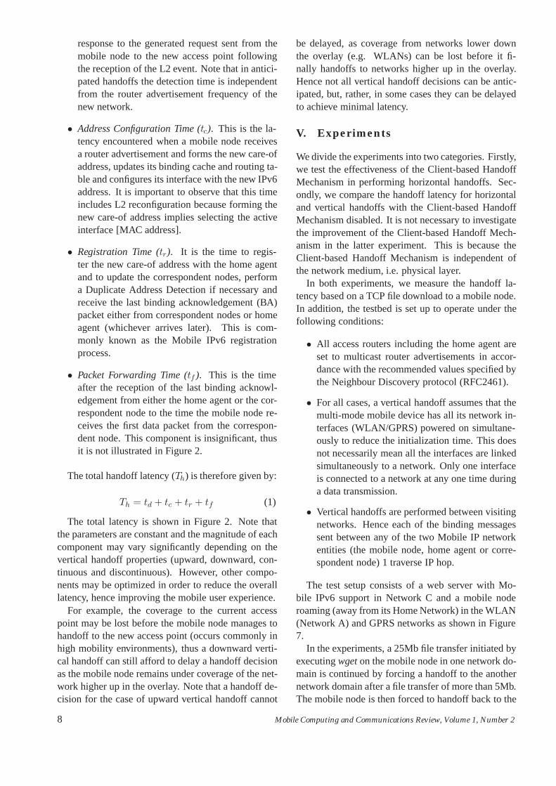
Handoff Latency (ms) Average RatioMIPv6 Enhancement handoff latency/
Min Mean Max Stdev download time
None 2277 4209 4759 1041 165Mechanism (Scenario 1) 112 633 895 241 29Mechanism (Scenario 2) 191 238 258 24 11
Table 1: The handoff latency during a 25Mb file download from a web server performed over 10 runs.
CorrespondentNode
Edge Router
Figure 3: Our (DTG) WLAN Mobile IPv6 Testbed.
previous network domain after a file transfer of morethan 15Mb. The forcing of a handoff after a sizeabledownload is decided arbitrarily to ensure TCP slowstart does not affect the consistency of the results fromthe tests. The traffic is captured with tcpdump run-ning on an intermediate router. Tcptrace is used toanalyse the traces obtained from tcpdump. However,modifications are required on a version of tcptraceto enable support for the processing of Mobile IPv6data packets.
Further details of the two experiments are describedin the following subsections.
V..1. Experiment: Effectiveness of theClient-based Handoff Mechanism
The impact of handoffs, with various parts of themechanism enabled, on a TCP download to the mo-bile node is investigated. Firstly, the Client-basedHandoff Mechanism without the TCP enhancementsis tested under discontinuous (Scenario 1) and con-tinuous (Scenario 2) handoff scenarios as discussedin Section IV.B. Then, the TCP enhancements builtas part of the Client-based Handoff Mechanism are
tested under the same conditions.
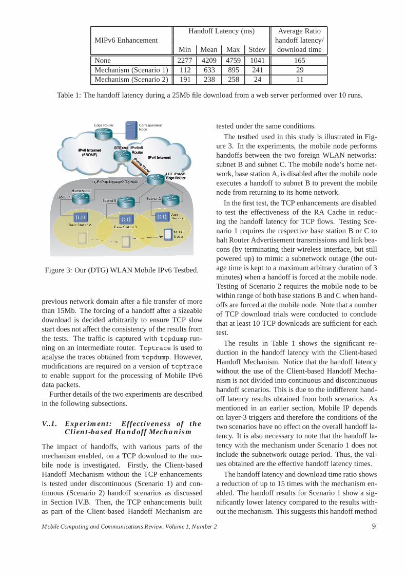
The testbed used in this study is illustrated in Fig-ure 3. In the experiments, the mobile node performshandoffs between the two foreign WLAN networks:subnet B and subnet C. The mobile node’s home net-work, base station A, is disabled after the mobile nodeexecutes a handoff to subnet B to prevent the mobilenode from returning to its home network.
In the first test, the TCP enhancements are disabledto test the effectiveness of the RA Cache in reduc-ing the handoff latency for TCP flows. Testing Sce-nario 1 requires the respective base station B or C tohalt Router Advertisement transmissions and link bea-cons (by terminating their wireless interface, but stillpowered up) to mimic a subnetwork outage (the out-age time is kept to a maximum arbitrary duration of 3minutes) when a handoff is forced at the mobile node.Testing of Scenario 2 requires the mobile node to bewithin range of both base stations B and C when hand-offs are forced at the mobile node. Note that a numberof TCP download trials were conducted to concludethat at least 10 TCP downloads are sufficient for eachtest.
The results in Table 1 shows the significant re-duction in the handoff latency with the Client-basedHandoff Mechanism. Notice that the handoff latencywithout the use of the Client-based Handoff Mecha-nism is not divided into continuous and discontinuoushandoff scenarios. This is due to the indifferent hand-off latency results obtained from both scenarios. Asmentioned in an earlier section, Mobile IP dependson layer-3 triggers and therefore the conditions of thetwo scenarios have no effect on the overall handoff la-tency. It is also necessary to note that the handoff la-tency with the mechanism under Scenario 1 does notinclude the subnetwork outage period. Thus, the val-ues obtained are the effective handoff latency times.
The handoff latency and download time ratio showsa reduction of up to 15 times with the mechanism en-abled. The handoff results for Scenario 1 show a sig-nificantly lower latency compared to the results with-out the mechanism. This suggests this handoff method
Mobile Computing and Communications Review, Volume 1, Number 2 9
MN to HABU from
by MNRA received
MN to CNBU from
RetransmittedTCP packets
Handoff latency
5500000
5600000
5700000
5800000
5900000
6000000
6100000
6200000
6300000
6400000
9.6 10.0 10.4 10.8 11.2 11.6 12.0 12.4 12.8 13.2
Seq
uenc
e of
fset
(by
tes)
Time (sec)
0
2000000
4000000
6000000
8000000
10000000
12000000
00:00 00:05 00:10 00:15 00:20 00:25
Seq
uenc
e of
fset
(by
tes)
Time (min)
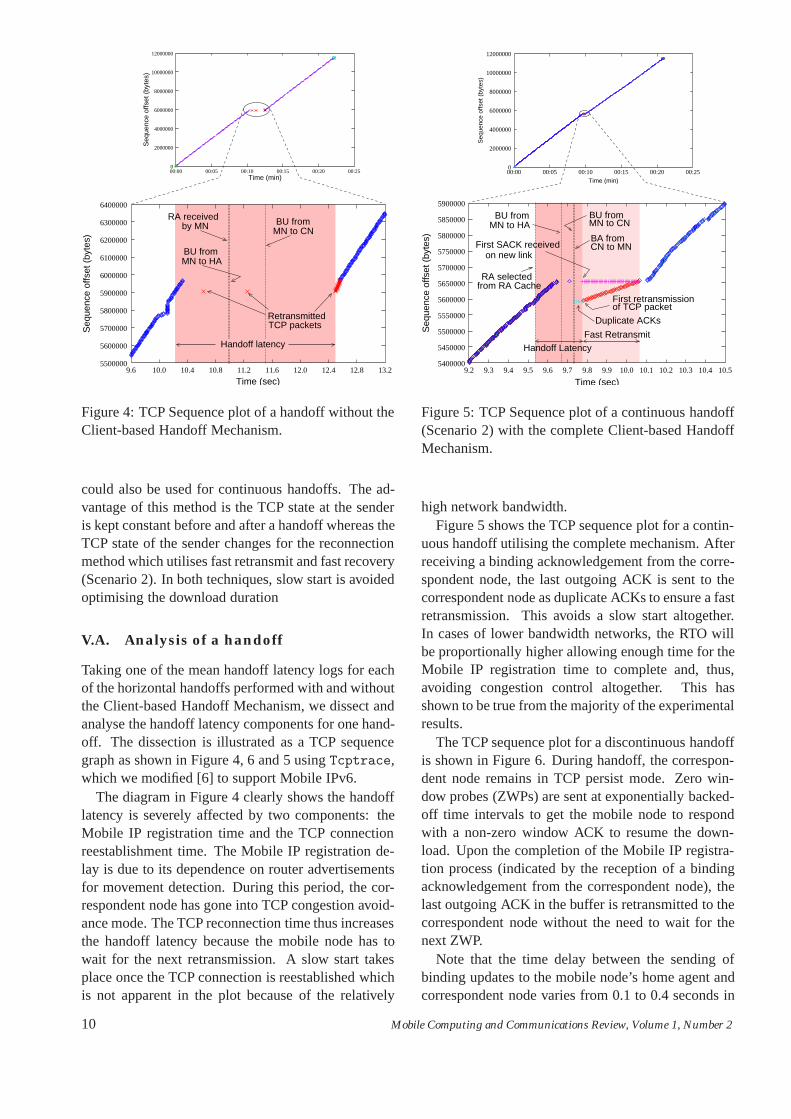
Figure 4: TCP Sequence plot of a handoff without theClient-based Handoff Mechanism.
could also be used for continuous handoffs. The ad-vantage of this method is the TCP state at the senderis kept constant before and after a handoff whereas theTCP state of the sender changes for the reconnectionmethod which utilises fast retransmit and fast recovery(Scenario 2). In both techniques, slow start is avoidedoptimising the download duration
V.A. Analysis of a handoff
Taking one of the mean handoff latency logs for eachof the horizontal handoffs performed with and withoutthe Client-based Handoff Mechanism, we dissect andanalyse the handoff latency components for one hand-off. The dissection is illustrated as a TCP sequencegraph as shown in Figure 4, 6 and 5 using Tcptrace,which we modified [6] to support Mobile IPv6.
The diagram in Figure 4 clearly shows the handofflatency is severely affected by two components: theMobile IP registration time and the TCP connectionreestablishment time. The Mobile IP registration de-lay is due to its dependence on router advertisementsfor movement detection. During this period, the cor-respondent node has gone into TCP congestion avoid-ance mode. The TCP reconnection time thus increasesthe handoff latency because the mobile node has towait for the next retransmission. A slow start takesplace once the TCP connection is reestablished whichis not apparent in the plot because of the relatively
Fast Retransmit
BU fromMN to CN
BA fromCN to MN
First retransmissionof TCP packet
Duplicate ACKs
MN to HABU from
First SACK receivedon new link
from RA CacheRA selected
Handoff Latency
0
2000000
4000000
6000000
8000000
10000000
12000000
00:00 00:05 00:10 00:15 00:20 00:25
Seq
uenc
e of
fset
(by
tes)
Time (min)
5400000
5450000
5500000
5550000
5600000
5650000
5700000
5750000
5800000
5850000
5900000
9.2 9.3 9.4 9.5 9.6 9.7 9.8 9.9 10.0 10.1 10.2 10.3 10.4 10.5
Time (sec)
Seq
uenc
e of
fset
(by
tes)
Figure 5: TCP Sequence plot of a continuous handoff(Scenario 2) with the complete Client-based HandoffMechanism.
high network bandwidth.Figure 5 shows the TCP sequence plot for a contin-
uous handoff utilising the complete mechanism. Afterreceiving a binding acknowledgement from the corre-spondent node, the last outgoing ACK is sent to thecorrespondent node as duplicate ACKs to ensure a fastretransmission. This avoids a slow start altogether.In cases of lower bandwidth networks, the RTO willbe proportionally higher allowing enough time for theMobile IP registration time to complete and, thus,avoiding congestion control altogether. This hasshown to be true from the majority of the experimentalresults.
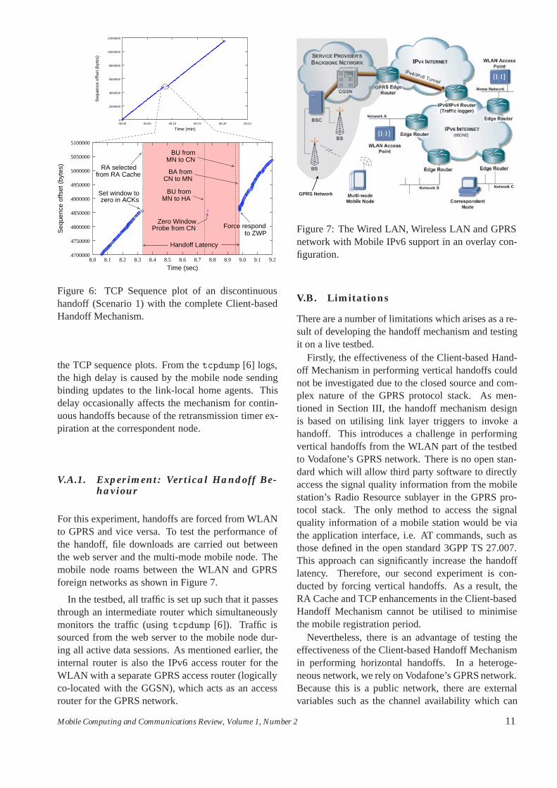
The TCP sequence plot for a discontinuous handoffis shown in Figure 6. During handoff, the correspon-dent node remains in TCP persist mode. Zero win-dow probes (ZWPs) are sent at exponentially backed-off time intervals to get the mobile node to respondwith a non-zero window ACK to resume the down-load. Upon the completion of the Mobile IP registra-tion process (indicated by the reception of a bindingacknowledgement from the correspondent node), thelast outgoing ACK in the buffer is retransmitted to thecorrespondent node without the need to wait for thenext ZWP.
Note that the time delay between the sending ofbinding updates to the mobile node’s home agent andcorrespondent node varies from 0.1 to 0.4 seconds in
10 Mobile Computing and Communications Review, Volume 1, Number 2
Probe from CNZero Window
RA selectedfrom RA Cache
BU fromMN to CN
MN to HABU from
CN to MNBA from
Handoff Latency
zero in ACKsSet window to
Force respondto ZWP
4700000
4750000
4800000
4850000
4900000
4950000
5000000
5050000
5100000
8.0 8.1 8.2 8.3 8.4 8.5 8.6 8.7 8.8 8.9 9.0 9.1 9.2
Seq
uenc
e of
fset
(by
tes)
Time (sec)
0
2000000
4000000
6000000
8000000
10000000
12000000
00:00 00:05 00:10 00:15 00:20 00:25
Seq
uenc
e of
fset
(by
tes)
Time (min)
Figure 6: TCP Sequence plot of an discontinuoushandoff (Scenario 1) with the complete Client-basedHandoff Mechanism.
the TCP sequence plots. From the tcpdump [6] logs,the high delay is caused by the mobile node sendingbinding updates to the link-local home agents. Thisdelay occasionally affects the mechanism for contin-uous handoffs because of the retransmission timer ex-piration at the correspondent node.
V.A.1. Experiment: Vertical Handoff Be-haviour
For this experiment, handoffs are forced from WLANto GPRS and vice versa. To test the performance ofthe handoff, file downloads are carried out betweenthe web server and the multi-mode mobile node. Themobile node roams between the WLAN and GPRSforeign networks as shown in Figure 7.
In the testbed, all traffic is set up such that it passesthrough an intermediate router which simultaneouslymonitors the traffic (using tcpdump [6]). Traffic issourced from the web server to the mobile node dur-ing all active data sessions. As mentioned earlier, theinternal router is also the IPv6 access router for theWLAN with a separate GPRS access router (logicallyco-located with the GGSN), which acts as an accessrouter for the GPRS network.
GPRS Network
(6BONE)
Figure 7: The Wired LAN, Wireless LAN and GPRSnetwork with Mobile IPv6 support in an overlay con-figuration.
V.B. Limitations
There are a number of limitations which arises as a re-sult of developing the handoff mechanism and testingit on a live testbed.
Firstly, the effectiveness of the Client-based Hand-off Mechanism in performing vertical handoffs couldnot be investigated due to the closed source and com-plex nature of the GPRS protocol stack. As men-tioned in Section III, the handoff mechanism designis based on utilising link layer triggers to invoke ahandoff. This introduces a challenge in performingvertical handoffs from the WLAN part of the testbedto Vodafone’s GPRS network. There is no open stan-dard which will allow third party software to directlyaccess the signal quality information from the mobilestation’s Radio Resource sublayer in the GPRS pro-tocol stack. The only method to access the signalquality information of a mobile station would be viathe application interface, i.e. AT commands, such asthose defined in the open standard 3GPP TS 27.007.This approach can significantly increase the handofflatency. Therefore, our second experiment is con-ducted by forcing vertical handoffs. As a result, theRA Cache and TCP enhancements in the Client-basedHandoff Mechanism cannot be utilised to minimisethe mobile registration period.
Nevertheless, there is an advantage of testing theeffectiveness of the Client-based Handoff Mechanismin performing horizontal handoffs. In a heteroge-neous network, we rely on Vodafone’s GPRS network.Because this is a public network, there are externalvariables such as the channel availability which can
Mobile Computing and Communications Review, Volume 1, Number 2 11
WLAN↔GPRS Handoff WLAN→GPRS GPRS→WLAN(the split in ms) Min Mean Max Stdev Min Mean Max Stdev
Detection Time (td) 200 808 1148 304 739 2241 3803 919Configuration Time (tc) 0.853 0.870 0.890 0.009 0.380 1.062 1.186 0.233Registration Time (tr) 2339 2997 3649 395 2585 4654 7639 1611Total Handoff Latency (Th) 3323 3806 4438 310 5322 6896 8833 1118
Table 2: Handoff latency partition (in ms) for WLAN↔GPRS taken over 10 runs
severely impact the overall handoff latency.Secondly, the TCP enhancement in the Client-based
Handoff Mechanism assumes the available bandwidthof the new path between the mobile node and corre-spondent node to be of the same order-of-magnitudeas the previous path. For horizontal handoffs, thiswould not be a problem since the RTT will be similar.However, in the case of vertical handoffs where theRTT can substantially differ from one network tech-nology to another, triggering a fast retransmit mayprove ineffective to reduce the handoff latency. A so-lution to this problem is to use the Binding UpdateBi-Casting technique [1].
Thirdly, the current design and implementation ofthe Client-based Handoff Mechanism are limited toasymmetric applications (e.g., thin-client computing)where the bulk of the data is received by the mobilenode because it would be ineffective to trigger, say,the TCP persist timer during a handoff at the corre-spondent node since data is being sent from the mo-bile node. Despite this limitation, it is sufficient todemonstrate the use of the handoff mechanism witha mobile computing application discussed in SectionVI. The mechanism can be extended to support sym-metric applications in future (see Section IX).
Finally, the experimental results are based on onemobile node. If more than one mobile node in thesame cell needed to handoff to an adjacent cell, therecould be a congestion of TCP packets in the base sta-tion of the new cell due to the simultaneous trans-mission of duplicate ACKs by the Client-based Hand-off Mechanism. Furthermore, the handoff of multiplemobile nodes each having active TCP sessions couldcause the synchronisation of TCP connections. It isnot possible to reliably investigate these scalability is-sues due to the unstable nature of the Mobile IPv6 im-plementation used in the testbed. These issues are leftfor future work.
V.C. Results and Discussion
Table 2 shows the breakdown of the handoff latencycomponents for vertical handoffs. The detection time
(td) and registration time (tr) are the two main com-ponents which greatly influence the overall handofflatency. This clearly shows the motivation for theClient-based Handoff Mechanism to minimise the ef-fect of these latency components on the handoff per-formance.
Comparing the results of horizontal (Table 1,Client-based Handoff Mechanism disabled) and verti-cal (Table 2) handoffs, there appears to be an insignif-icant difference in the total handoff latency betweenWLAN↔WLAN and WLAN→GPRS. The horizon-tal handoff latency range from 2.277 seconds to 4.759seconds with a mean time of 4.209 seconds. In com-parison, the WLAN→GPRS handoff latency rangefrom 3.323 seconds to 4.438 seconds with a meantime of 3.806 seconds. Both of these handoff latencyranges are similar and the difference in the mean val-ues is evident from the standard deviation of the re-sults.
The more significant result, however, is theGPRS→WLAN handoff latency which range from5.322 seconds to 8.833 seconds with a mean timeof 6.896. This handoff latency is greater by approx-imately 2 seconds. The reasons for the higher la-tency is due to the network characteristic of GPRS:the larger packet buffers in the GGSN nodes and thestark contrast in network bandwidth. The maximumdata rates for WLAN and GPRS are 11Mbps symmet-ric and 48Kbps asymmetric (downlink rate is definedby GPRS PC Card specification), respectively.
VI. An Application of End-SystemApproach to Mobility Manage-ment: Mobile VNC
In this section, we envisage and realise an applicationwhich makes heterogeneous networking, i.e. border-less computing, possible and useful. One such appli-cation is thin-client computing.
Contrary to the trend of a “thick” mobile device,e.g. laptops, providing better support for distributedapplications or stand-alone applications, a stateless
12 Mobile Computing and Communications Review, Volume 1, Number 2
mobile device is advocated and an architecture tomake such devices feasible for wireless computing isproposed.
Previously it has not been possible to provide agood user experience for such applications of mobilecomputing in a public network infrastructure, how-ever, it is increasingly becoming a reality with the rollout of higher data rate services such as 3G and WLANhotspots and the functions offered by the Client-basedHandoff Mechanism.
Unlike stateful devices, stateless devices do not runapplication or system code on the appliance. In thisarticle, it is defined as the execution of the windowingsystem and applications entirely on a server throughthin clients. Thin-client systems are a proven tech-nology which is well suited for fixed broadband net-work connections. Upon a disconnection in the link,or poor network coverage, the user response rate be-comes problematic. Therefore, a completely statelessclient may not be ideal for an environment where net-work coverage can be unpredictable. A truly portablestateless device will only be ideal in an enclosure,such as a building or an aeroplane. A method to adaptand cope with changes in network conditions is nec-essary to minimise disruptions to human computer in-teraction (HCI).
There are several types of thin-client applications[7]. This research is only concerned with ultra-thinclient systems due to its centralised nature and its abil-ity to support multiple users. In addition, the systemis ideally suited for mobile devices because it imposesno user data storage, extremely low power consump-tion and the end product is lightweight. The simplicityof administrating an ultra-thin client system is the keydriver to extend its use to a high mobility environment.
Thin-client systems offer user mobility by means ofproviding user access to their desktop virtually any-where in the world as long as there is a relatively highspeed network connection. However, device mobil-ity of thin-clients has not been explored in a globalenvironment. The Videotile3, used an indoor wire-less ATM technology limiting its use inside a building.However, with the advent of WLAN and higher speeddata access through cellular networks (e.g., 3G), thefeasibility of thin-client device mobility is becomingever more realistic. With the lower power consump-tion on the battery of the mobile device, server powercomputing, close to zero administration, greater appli-cation robustness and no risk to loss of data throughtheft or damage there are more advantages to move to
3The Videotile, 1996http://www.cl.cam.ac.uk/Research/DTG/attarchive/tile.html
thin-clients. Such a system would be highly appropri-ate for corporate employees where information is nat-urally accessible through a centralised infrastructureproviding greater security.
This section introduces an architecture which lever-ages the mobility management solution in this paperfor supporting the roaming of mobile thin-client de-vices in wireless IP networks (rather than ATM).
VI.A. The Mobile VNC Architecture
The concept of Mobile VNC is introduced in this sec-tion. This term is defined as a system which enablesserver-based computing whilst the user is roamingwith a tetherless and stateless thin-client device run-ning a permanent VNC Viewer.
Supporting roaming thin-client devices involves anumber of entities: a VNC Server, a VNC Proxy, aVNC Viewer and a signaling mechanism to transfer aVNC session between VNC proxies. A VNC Proxy isintroduced to resolve the network latency issue. Theadvantages of introducing such an entity into the net-work infrastructure are:
• The local cache reduces the number of TCP re-transmissions and screen updates between theserver and client;
• Minimise HCI disruptions due to micro-mobilityhandoffs
• The enforcement of network security as firewallare not by-passed;
• Transparent accounting and billing; and
• Link speeds and bandwidth between the serverand proxy can be guaranteed with Quality of Ser-vice (QoS) mechanisms such as Integrated Ser-vices (IntServ) and Differentiated Services (Diff-Serv) since the proxy server will be part of thefixed infrastructure.
A VNC Proxy is autonomous and is managed bythe local network operator. If a network does not havea VNC Proxy in place, then the VNC client is able tocommunicate directly with the VNC Server.
Two other important components are necessary tocreate the architecture: guaranteeing the QoS betweenthe VNC Server and the VNC Proxy; and the signalingmechanism to move a roaming client’s VNC sessionbetween VNC Server and VNC Proxies.
The QoS between the VNC Server and VNC Proxycan be guaranteed through DiffServ or IntServ. Thediagram in Figure 11 illustrates how this may be done
Mobile Computing and Communications Review, Volume 1, Number 2 13
MN oAR nAR
Context Transfer/Handoff Trigger
tseuqeRTC
CTAR
CTD
Time
CTAR ReplyCTD Reply
Figure 8: Mobile-controlled: Context transfer proto-col signaling message sequence diagram initiated bythe mobile node (MN).
using the Reservation Protocol (RSVP) which is acontrol protocol to provide QoS for IntServ.
The Context Transfer Protocol (CXTP) (RFC4067)proposed within the Seamoby IETF working groupcharter is used to deal with transferring information(or context) of a mobile node’s VNC session betweenVNC Proxies. The signaling initiation can either benetwork-controlled or mobile-controlled. In this re-search, the focus is to offer the mobile node full con-trol of its own mobility. The Client-based HandoffMechanism is extended to support the Context Trans-fer Trigger required to initiate the transfer of contextbetween access routers from the mobile node, in thiscase, the context is the VNC session of the mobilenode active in a VNC Proxy.
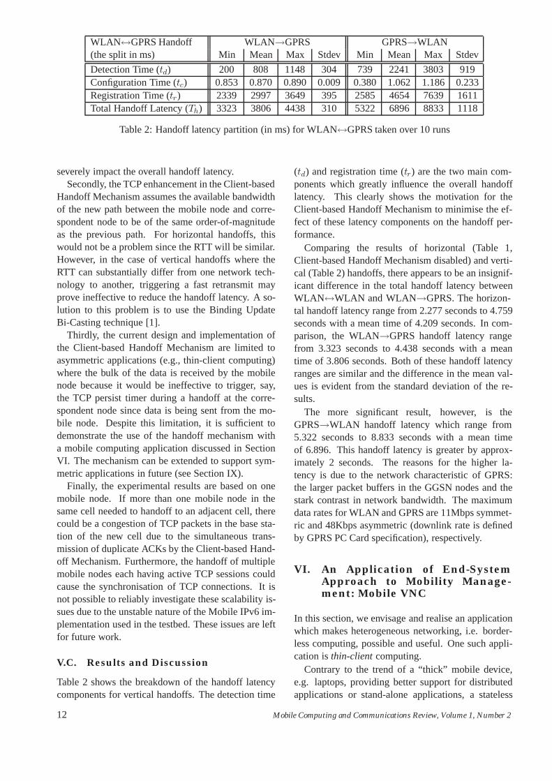
Figure 8 illustrates the signaling involved in thecontext transfer. An L2 trigger in the Client-basedHandoff Mechanism simultaneously invokes the Con-text Transfer Trigger.
This initiates the sending of a Context Transfer Ac-tivate Request (CTAR) message which is repeatedlysent at a specified time interval from the VNC Viewermanager on the client to the VNC Proxy manager toguarantee a context transfer.
This initiates the sending of a Context Transfer Ac-tivate Request (CTAR) message to the nAR. This mes-sage contains the nAR and oAR IP addresses, the oldcare-of address of the mobile node, the new care-ofaddress of the mobile node automatically configuredusing a Router Advertisement message from the nAR,a request for the mobile node’s VNC session to betransferred and a token generated by the mobile nodeto authorise the context transfer from the oAR to thenAR.
Once the nAR receives the CTAR message, it sendsa Context Transfer Request (CT Request) message tothe oAR. This contains the mobile node’s previouscare-of address, a request for the mobile node’s VNCsession to be transferred and the token generated bythe mobile node authorising the context transfer.
Home Agent
Subnet A
Subnet B
Subnet CSubnet C
Mobile Node
Base Station A
Base Station B
BaseStation C
VNC Server VNC Proxy
NC ProxyVNNC
Figure 9: Supporting VNC mobility
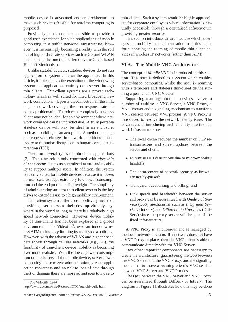
The last 64-bit of the IPv6 address is set to the sameidentifier value for all VNC Proxies in the networkshown in Figure 9. Therefore, the VNC Proxy IPaddress is a combination of the 64-bit prefix alreadypresent in the Router Advertisement and a universal64-bit identifier for VNC Proxies in all networks in-stead of a unique 64-bit interface identifier as specifiedby RFC2374. Thus, the CTAR message sent from themobile node VNC Viewer manager will always reachthe VNC Proxy manager in the new network in whichthe mobile node has joined.
The CTAR message contains the port number of theold VNC Proxy. The number doubles as a methodto uniquely identify the mobile node’s VNC session.When the new VNC Proxy manager receives a uniqueCTAR message, it then sends a CT Request to theold VNC Proxy manager. Any subsequent duplicateCTAR messages are ignored. The old VNC Proxymanager responds to the new VNC Proxy managerwith a CTD message containing the QoS informationand the VNC Server name.
Note that the mobile node also connects to a VNCProxy while in its home network. Hence, the VNCServer name does not need to be known by the mobilenode.
Below is an example entry of a VNC session theVNC Proxy manager would be proxying:
{VNC Server IP address}::5901 ↔ {VNC Proxy IPaddress}::5999
or{VNC Server name}::5901 ↔ {VNC Proxy
name}::5999
The VNC Viewer manager in the mobile nodewould then connect to the VNC Proxy in the followingway:
vncviewer {VNC Proxy IP address}::5999
14 Mobile Computing and Communications Review, Volume 1, Number 2
orvncviewer {VNC Proxy name}::5999
Once a CTD message is received from the old VNCProxy manager, the new VNC Proxy manager invokesthe VNC Proxy to open a session to the VNC Server.This allows screen updates and user input/output tobe buffered and forwarded between the Server andViewer. RSVP is initiated to perform a resource reser-vation, based on the QoS information in the CTD mes-sage, for the link between the VNC Proxy and theVNC Server (a receiver-orientated resource reserva-tion, RFC2205). The new VNC Proxy issues a newVNC port number for the VNC Viewer to connect tothis open session.
CXTP is extended to allow the new VNC Proxymanager to return a CTAR Reply message, which con-tains the new VNC Proxy port number issued for theVNC Viewer manager to connect the VNC Viewer tothe VNC Proxy. Once the client connects to the VNCProxy, a CTD Reply message is sent from the newVNC Proxy manager to the old VNC Proxy managerto terminate and tear down the relevant VNC sessionand RSVP path, respectively. If the old VNC Proxydoes not receive this message, the session will expireafter a set time. During an active VNC session be-tween the VNC Server and VNC Proxy, RSVP sendsperiodic refresh messages to maintain the state alongthe reserved path.
VI.B. Experiments and Experiences
In all of the experiments, the following conditionswere set for consistency in the final result.
• The VNC software was provided by RealVNCLtd. The VNC Server was installed in the mo-bile node’s home domain; the VNC Proxy wasinstalled in the Access Router (AR) of each net-work; and the VNC Viewer was installed on themobile node.
• A VNC session was initiated at the server so aVNC Viewer can connect to the session withoutany delay.
• tcpdump was used to log all traffic activitiesbetween the VNC Server and connecting VNCViewer.
• Upon the execution of the VNC Viewer on themobile device, a video clip was played usingmplayer4. The sample video clip was a 25 framesper second MPEG-2 video.
4mplayer, http://www.mplayerhq.hu/
0 1 2 3 4 5
20000000
80000000
100000000
120000000
60000000
40000000
Time (minutes)
0
Seq
uenc
e of
fset
(by
tes)
Raw 8-bit colourZRLE 16-bit colourZRLE 8-bit colour
TCP retransmissionHextile 8-bit colour
Figure 10: TCP sequence number plots for the varioustypes of encoding offered by VNC. The mobile clientrunning the VNC Viewer was tested under a handofffrequency of 6 handoffs per minute.
• The VNC Viewer was constrained to connect tothe VNC Server for a limited time of 5 minuteswhich was sufficient to conduct the tests.
• The latency involved in setting up the securityassociation and QoS paths were not considered.
Three experiments were carried out to investigatethe effectiveness of the Client-based Handoff Mecha-nism and the VNC Proxy.
VI.B.1. Experiment 1
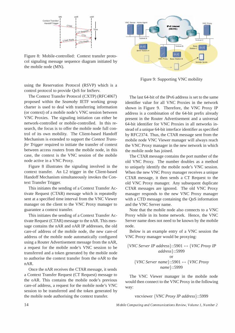
The first experiment involved the selection of a suit-able type of VNC encoding used in the testing ofthe overall system. The version of VNC used in thetests offered the following encoding: raw, hextile andZRLE (Zlib Run length Encoding).
VNC Server can send screen updates to the VNCViewer in 8-bit and 16-bit colour. 8-bit colour wasselected for all of the encoding schemes, and 16-bitcolour was selected only for the encoding schemewhich required the least amount of screen updates tobe sent to the client. The VNC encoding scheme withthe least number of screen updates was used for theremainder of the experiments.
The experiment did not simply involve a static ses-sion to a fixed client. The client was forced to perform6 handoffs per minute to help determine the best VNCencoding scheme for a non-stationary user.
Figure 10 shows the result of the first experiment.Notice the raw encoding scheme has many times moreTCP packet transmissions than the other encodingschemes due to the requirement for a greater screenupdate frequency. This scheme is highly unsuitablefor mobile users when taking into account the averagepacket loss shown in Table 3. The encoding scheme
Mobile Computing and Communications Review, Volume 1, Number 2 15
with the least screen updates and packet loss is clearlyZRLE using 8-bit colour. This encoding scheme isused for the remaining experiments. Increasing thecolour to 16-bit causes a higher number of packetloss as compared to the Hextile encoding making thehigher colour option undesirable for the mobile client.The higher colour option will be advantageous for dis-playing video clips, otherwise, normal office applica-tions do not require such a high colour depth.
VNC Encoding Scheme Packet Loss
Raw 913Hextile 123ZRLE (8-bit colour) 118ZRLE (16-bit colour) 256
Table 3: Average packet loss from 10 runs of a clientrunning a 5-minute VNC session with video playbackperforming 6 handoffs per minute.
VI.B.2. Experiment 2
The second experiment looked into the mobility as-pect of stateless mobile thin-client computing. Thesystem was implemented as in Figure 9.
The intermediary routers in the testbed did not guar-antee quality of service since this issue in IPv6 hadnot yet been agreed and set by the service providers’routers.
VNC Serve
VNC Proxy VNC Client
Wireless Link
Figure 11: Guaranteeing link reliability over the IPv6Internet
The logical diagram of how QoS could be guaran-teed is shown in Figure 11. The diagram shows how aRSVP link would fit into the testbed. RSVP couldnot be implemented on routers in the IPv6 Internet(6BONE), thus the link was emulated by provision-ing a direct 100Mbps Ethernet link between the VNCServer and VNC Proxy.
The mobile node was forced to perform a numberof handoffs per minute. The condition of the tests wasthat the mobile node had to be within the wireless net-work coverage of at least two points of attachment,i.e. base station A and B as illustrated in Figure 9.The first set of tests was to observe the effectiveness
0 1 2 3 4 5 6
3.2
3.4
3.6
3.8
4
4.2
4.4
4.6
4.8
5
x 104
Mobility Velocity (handoffs/min)
Ave
rage
Thr
ough
put (
byte
s/se
c)
without TCP enhancement & with VNC Proxywithout TCP enhancement & without VNC Proxywith TCP enhancement & with VNC Proxywith TCP enhancement & without VNC Proxy
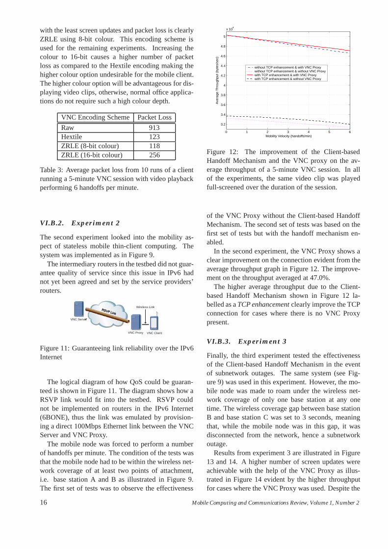
Figure 12: The improvement of the Client-basedHandoff Mechanism and the VNC proxy on the av-erage throughput of a 5-minute VNC session. In allof the experiments, the same video clip was playedfull-screened over the duration of the session.
of the VNC Proxy without the Client-based HandoffMechanism. The second set of tests was based on thefirst set of tests but with the handoff mechanism en-abled.
In the second experiment, the VNC Proxy shows aclear improvement on the connection evident from theaverage throughput graph in Figure 12. The improve-ment on the throughput averaged at 47.0%.
The higher average throughput due to the Client-based Handoff Mechanism shown in Figure 12 la-belled as a TCP enhancement clearly improve the TCPconnection for cases where there is no VNC Proxypresent.
VI.B.3. Experiment 3
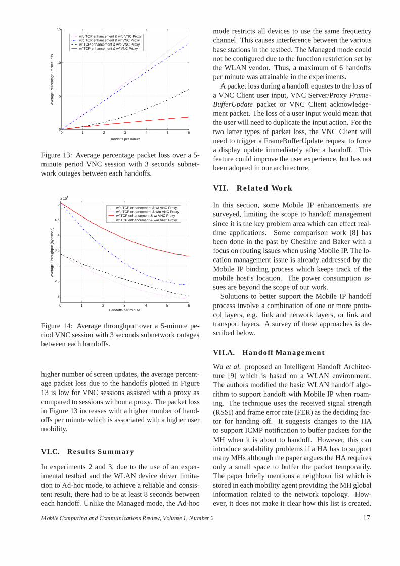
Finally, the third experiment tested the effectivenessof the Client-based Handoff Mechanism in the eventof subnetwork outages. The same system (see Fig-ure 9) was used in this experiment. However, the mo-bile node was made to roam under the wireless net-work coverage of only one base station at any onetime. The wireless coverage gap between base stationB and base station C was set to 3 seconds, meaningthat, while the mobile node was in this gap, it wasdisconnected from the network, hence a subnetworkoutage.
Results from experiment 3 are illustrated in Figure13 and 14. A higher number of screen updates wereachievable with the help of the VNC Proxy as illus-trated in Figure 14 evident by the higher throughputfor cases where the VNC Proxy was used. Despite the
16 Mobile Computing and Communications Review, Volume 1, Number 2
0 1 2 3 4 5 60
5
10
15
Handoffs per minute
Ave
rage
Per
cent
age
Pac
ket L
oss
w/o TCP enhancement & w/o VNC Proxyw/o TCP enhancement & w/ VNC Proxyw/ TCP enhancement & w/o VNC Proxyw/ TCP enhancement & w/ VNC Proxy
Figure 13: Average percentage packet loss over a 5-minute period VNC session with 3 seconds subnet-work outages between each handoffs.
0 1 2 3 4 5 6
2
2.5
3
3.5
4
4.5
5
x 104
Handoffs per minute
Ave
rage
Thr
ough
put (
byte
s/se
c)
w/o TCP enhancement & w/ VNC Proxyw/o TCP enhancement & w/o VNC Proxyw/ TCP enhancement & w/ VNC Proxyw/ TCP enhancement & w/o VNC Proxy
Figure 14: Average throughput over a 5-minute pe-riod VNC session with 3 seconds subnetwork outagesbetween each handoffs.
higher number of screen updates, the average percent-age packet loss due to the handoffs plotted in Figure13 is low for VNC sessions assisted with a proxy ascompared to sessions without a proxy. The packet lossin Figure 13 increases with a higher number of hand-offs per minute which is associated with a higher usermobility.
VI.C. Results Summary
In experiments 2 and 3, due to the use of an exper-imental testbed and the WLAN device driver limita-tion to Ad-hoc mode, to achieve a reliable and consis-tent result, there had to be at least 8 seconds betweeneach handoff. Unlike the Managed mode, the Ad-hoc
mode restricts all devices to use the same frequencychannel. This causes interference between the variousbase stations in the testbed. The Managed mode couldnot be configured due to the function restriction set bythe WLAN vendor. Thus, a maximum of 6 handoffsper minute was attainable in the experiments.
A packet loss during a handoff equates to the loss ofa VNC Client user input, VNC Server/Proxy Frame-BufferUpdate packet or VNC Client acknowledge-ment packet. The loss of a user input would mean thatthe user will need to duplicate the input action. For thetwo latter types of packet loss, the VNC Client willneed to trigger a FrameBufferUpdate request to forcea display update immediately after a handoff. Thisfeature could improve the user experience, but has notbeen adopted in our architecture.
VII. Related Work
In this section, some Mobile IP enhancements aresurveyed, limiting the scope to handoff managementsince it is the key problem area which can effect real-time applications. Some comparison work [8] hasbeen done in the past by Cheshire and Baker with afocus on routing issues when using Mobile IP. The lo-cation management issue is already addressed by theMobile IP binding process which keeps track of themobile host’s location. The power consumption is-sues are beyond the scope of our work.
Solutions to better support the Mobile IP handoffprocess involve a combination of one or more proto-col layers, e.g. link and network layers, or link andtransport layers. A survey of these approaches is de-scribed below.
VII.A. Handoff Management
Wu et al. proposed an Intelligent Handoff Architec-ture [9] which is based on a WLAN environment.The authors modified the basic WLAN handoff algo-rithm to support handoff with Mobile IP when roam-ing. The technique uses the received signal strength(RSSI) and frame error rate (FER) as the deciding fac-tor for handing off. It suggests changes to the HAto support ICMP notification to buffer packets for theMH when it is about to handoff. However, this canintroduce scalability problems if a HA has to supportmany MHs although the paper argues the HA requiresonly a small space to buffer the packet temporarily.The paper briefly mentions a neighbour list which isstored in each mobility agent providing the MH globalinformation related to the network topology. How-ever, it does not make it clear how this list is created.
Mobile Computing and Communications Review, Volume 1, Number 2 17
The architecture does not indicate how it will work forwireless network technologies other than WLAN. Noimplementation description or results have been givenin this article.
Yokota et al. proposes a link-layer assisted method[10] to improve handoff performance in Mobile IPv4networks. It does not introduce modifications to Mo-bile IP like that of Wu et al. but introduces a newnetwork entity called a MAC Bridge and modifica-tions to the WLAN Access Point (AP) instead. TheAP and MAC Bridge functions appear to be similar tothat of a HA and FA where the MAC address of theMobile Node needs to be established before proceed-ing with the Mobile IP mechanism. This association isrequired to minimise packet loss during the Mobile IPregistration period. The technique may be redundantsince packets from the CN can still be received duringthe registration process with the new FA. However, inthe case of AP failure or hard handoffs, the techniquecan prove to be valuable.
Balakrishnan et al. proposed Snoop [11] which isaimed at improving TCP applications based on thelink layer information. It assumes the wireless linkis lossy, thus introduces a way to sniff in-flight pack-ets using a base station as a proxy. This proxy sendsACKs and suppresses duplicate ACKs to avoid thesender using congestion control when there are packetlosses over the wireless link. These specialised basestations are required to have a large memory and pro-cessing power to store network packets while handoffstake place.
Omae et al. proposed and showed simulated re-sults of a method to improve handoff performance inMobile IPv6 networks with the use of a buffer imple-mented at the mobile node [12]. UDP and TCP pack-ets are buffered in the mobile node in order to min-imise packet loss in the event of a handoff. This tech-nique can affect real-time traffic. In [13] a techniqueto improve handoff for real-time traffic however, em-ploys a two-path handoff technique which uses prop-erties of IPv6 and the Integrated Services (IntServ)QoS architecture.
Freeze-TCP by Goff et al. [14] and the more re-cent Internet Draft by Eggert et al. [15] are tech-niques to reduce handoff disruptions to TCP applica-tions. The former solution makes use of the TCP per-sist mode method to stop the transmission of packets.The later solution uses the fast retransmit and fast re-covery TCP mechanism to quickly resume a TCP con-nection. However, both techniques are not optimisedfor various types of handoff scenarios.
VII.B. Subnetwork Outage (Disconnec-tion)
The techniques discussed in the previous sectionssolve handoff issues but neglect cases when there aresubnetwork outages [16]. Nonetheless, there is a tech-nique called M-TCP [17] which take this factor intoconsideration. It proposes the use of delayed ACKssent on behalf of a receiver by means of a proxy toplace the sender in persist mode to avoid losing pack-ets during handoffs.
Proposals before the efforts recently initiated by theIETF working groups do not consider disruptions toTCP sessions based on the link type and network layersignaling (i.e. Mobile IP, IPv6) and therefore may notnecessarily work and could in fact introduce unneces-sary delays or overheads. Although the discussed so-lutions maintain end-to-end semantics, other solutionsdo not abide by this rule. MTCP [18] and I-TCP [19]break this rule by splitting the wireless and wired partand place, what is effectively, a proxy which acts onbehalf of a mobile host to improve TCP performance.
VII.C. Efforts within the IETF
Two documents have been proposed within the mo-bileip charters (mip4 and mip6) to reduce the handofflatency of Mobile IP. These are Low Latency MobileIPv4 Handoffs [20] and Fast Handovers for MobileIPv6 (RFC 4068).
Recently, Williams and Pagtzis proposed a schemecalled Localised Mobility Management (LMM) [21,22] to minimise the Mobile IP signaling traffic to theHome Agent and/or Correspondent Node(s) for intra-domain mobility. They argue that signalling messagescould take more than one hundred milliseconds whenthe mobile node is at some geographical and topologi-cal distance away from the CN and HA. This increaseshandoff latency, hence, packet loss at the old AccessRouter for the MN. The scheme introduces a LMMagent at the local subnet level to allow the MN to con-tinue receiving traffic on the new subnet without anychange in the HA or CN binding. However, this rein-troduces triangular routing to Mobile IPv6. Thus, thescheme may not scale since LMM agents are requiredto minimise the length of the triangle leg it introducedto reduce the handoff latency. The LMM scheme isyet to be regarded as a proven technique.
Another IETF working group called PILC looksinto defining how the IP Protocol Suite works withdifferent types of link layers. A recent Internet Draft[23] attempts to characterise links and set out best-practice suggestions for Internet subnetwork design-
18 Mobile Computing and Communications Review, Volume 1, Number 2
ers. One recommendation made by the document toavoid discarding packets during a subnetwork outageis for an interface to be defined to the IP and higherlayers allowing it to refuse sending packets when thereis an outage, and for the interface to automatically askIP for new packets once the link has been restored.If this is not feasible, it is recommended that the linklayer retains one or more of the packets which couldnot be transmitted during the outage period, and re-transmits these packets on reconnection.
A recent work in the IETF, based on the effortsby PILC, includes the development of the TRIGTRANframework [24]. It proposes a mechanism to alert thetransport layer about changes in individual links alongthe network path from source to destination. With thisframework, hosts may request notification when trig-ger events such as Connectivity Interrupted, Connec-tivity Restored and Packets Discarded by Subnet oc-cur.
The IETF PILC working group is in its early stagesand therefore are lacking experimental support. Thereis no concrete implementation to validate their pro-posal and it is hoped these efforts would be widelysupported in the near future.
VIII. Conclusions
The impact of the research work described in thisarticle is twofold. Firstly, the Client-based HandoffMechanism is a simple solution to provide a con-trolled handoff technique and a reduction in the hand-off latency for IPv6 networks with Mobile IP sup-port, i.e. beyond 3G networks. It reduces the mo-bile node’s dependence on Mobile IP mechanisms:the router advertisement interval and the router solic-itation behaviour. The concept of an RA cache andexternally triggering the TCP mechanism have beenshown to substantially improve the mobile computingexperience as demonstrated in our testbed.
Secondly, the thin-client application shows how totake full advantage of the Client-based Handoff Mech-anism and the next generation Internet to overcomethe unpredictability and unreliability of IP network-ing. A Mobile VNC Architecture is proposed andevaluated to support mobile thin-client computing inwireless IP networks as opposed to the requirementfor wireless ATM networks (i.e., the Videotile). Re-sults show a high and relatively consistent throughputwhen a mobile thin-client is running a VNC session.In the event of subnetwork outages, packet loss andthe effect of TCP slow start are entirely avoided.
IX. Future Work
The current prototype of the Client-based HandoffMechanism evaluated in the testbed is well suited tosignificantly limiting packet loss for a mobile node’sdownload (asymmetric data transfer) stream whenhanding off. This can be extended to support sym-metric data transfers. For example, the data rate forthe upload stream can be maintained by upsetting theTCP persist timer in the mobile node.
Furthermore, as an extension to our solution, theuser can have the option of overriding the handoffmechanism to select their preferred network.
Vidales, Patanapongpibul and Chakravorty [2] be-gan some early implementation work which makesuse of the Client-based Handoff Mechanism in a het-erogeneous network environment.
Mobile-controlled handoff has its benefits for het-erogeneous networking. Nevertheless, there are sev-eral advantages for network-assisted handoffs. Oneadvantage is that the network has the status informa-tion of the base stations adjacent to the current basestation to which the mobile host is attached. Anotheradvantage is the ability to optimise the radio resourceacross the entire network by ensuring the mobile hosthas a channel to the network. These advantages canbe leveraged by the mobile host to further enhance themobile computing experience. For heterogeneous net-working, it is ideal that the status of the network andradio resource are freely available. A new protocoldesigned to be compatible with various wireless net-work technologies would be one solution for the mo-bile host to receive network status information. Such aprotocol can be integrated into our handoff algorithmto achieve network-assisted handoffs.
Peering agreements is an issue that will be debatedwell into the future and will become an increasinglychallenging problem when mobile devices are able toroam to any type of network. This discussion is be-yond the scope of this article but is an area for furtherinvestigation.
Finally, in addition to supporting mobile thin-clientcomputing in the wide area network, a mobile nodecould run its own operating system with the Codanetwork file system [25] for data storage. Suitablyadapted versions of the Coda file server and Codaproxy file server could be used as substitutes for theVNC server and VNC proxy, respectively.
X. Acknowledgement
The authors would like to thank Pablo Vidales, Ra-jiv Chakravorty, Andrew Campbell and Jon Crowcroft
Mobile Computing and Communications Review, Volume 1, Number 2 19
for their support. We would also like to thank theComputer Laboratory and the Engineering Depart-ment for facilitating the roll out of the Mobile IPv6testbed. Thanks also to Vodafone for their experimen-tal 3G network in Cambridge, UK. EPSRC and AT&TLabs - Cambridge made this project possible by pro-viding funding for equipment and personnel.
References
[1] P. Vidales, L.B. Patanapongpibul, G. Mapp,and A. Hopper, “Experiences with Heteroge-neous Wireless Networks - Unveiling the Chal-lenges,” in the Proceedings of the 2nd Inter-national Working Conference on PerformanceModeling and Evaluation of Heterogeneous Net-works (HET-NETs’04), July 2004.
[2] P. Vidales, L.B. Patanapongpibul, andR. Chakravorty, “Ubiquitous Networkingin Heterogeneous Environments,” in the Pro-ceedings of the 8th International Workshop onMobile Multimedia Communications (MoMuc),October 2003.
[3] R. Chakravorty, P. Vidales, K. Subramanian,I. Pratt, and J. Crowcroft, “Practical expe-riences with wireless networks integration us-ing mobile ipv6,” Poster and Extended Abstractin the Annual ACM/IEEE International Con-ference on Mobile Computing and Networking(MOBICOM), September 2003.
[4] “An Introduction to the Vodafone GPRS Envi-ronment and Supported Services,” Tech. Rep.Issue 1.1/1200, Vodafone Ltd., December 2000.
[5] Mark Stemm and Randy H. Katz, “VerticalHandoffs in Wireless Overlay Networks,” Mo-bile Networks and Applications, vol. 3, no. 4, pp.335–350, 1999.
[6] “tcptrace(http://www.tcptrace.org),tcptrace+(http://www-lce.eng.cam.ac.uk/∼lbp22/opensource.html),tcpdump(http://www.tcpdump.org),iperf(http://dast.nlanr.net/projects/iperf/),” .
[7] J. Nieh, S. J. Yang, and N. Novik, “Mea-suring Thin-Client Performance Using Slow-Motion Benchmarking,” ACM Transactions onComputer Systems, vol. 21, no. 1, pp. 87–115,February 2003.
[8] Stuart Cheshire and Mary Baker, “Internet Mo-bility 4x4,” in Proceedings of the ACM Con-ference on Applications, Technologies, Architec-tures, and Protocols for Computer Communica-tions (SIGCOMM), August 1996, pp. 318–329.
[9] Nen-Fu Huang Jon Chiung-Shien Wu, Chieh-Wen Chieng and Gin-Kou Ma, “IntelligentHandoff for Mobile Wireless Internet,” MobileNetworks and Applications, vol. 6, no. 1, pp. 67–79, 2001.
[10] Toru Hasegawa Hidetoshi Yokota, Akira Idoueand Toshihiko Kata, “Link Layer AssistedMobile IP Fast Handoff Method over Wire-less LAN Networks,” in Proceedings of theSeventh Annual ACM/IEEE International Con-ference on Mobile Computing and Networking(MOBICOM), Sept. 2002, pp. 131–139.
[11] H. Balakrishnan, S. Seshan, and R. H. Katz,“Improving reliable transport and handoff per-formance in cellular wireless networks,” ACMWireless Networks, vol. 1, no. 4, pp. 469–481,1995.
[12] Koji Omae, Takehiro Ikeda, Masahiro Inoue,Ichiro Okajima, and Narumi Umeda, “MobileNode Extension Employing Buffering Functionto Improve Handoff Performance,” in Proceed-ings of the Fifth International Symposium onWireless Personal Multimedia Communications,2002, vol. 1, pp. 62–66.
[13] Janise McNair, Ian F. Akyildiz, and Michael D.Bender, “Handoffs for Real-Time Trafficin Mobile IP Version 6 Networks,” inIEEE Global Telecommunications Conference(GLOBECOM), November 2001, vol. 6, pp.3463–3467.
[14] T. Goff, J. Moronski, D. S. Phatak, and V. Gupta,“Freeze-TCP: A true end-to-end TCP enhance-ment mechanism for mobile environments,” inProceedings of INFOCOM, 2000, pp. 1537–1545.
[15] L. Eggert, S. Schuetz, and S. Schmid, “TCP Ex-tensions for Immediate Retransmissions,” IETFInternet-Draft, June 2001, draft-eggert-tcpm-tcp-retransmit-now-02.txt, work in progress.
[16] G. H. Forman and J. Zahorjan, “The Challengesof Mobile Computing,” Computer, vol. 27, no.4, pp. 38–47, April 1994.
20 Mobile Computing and Communications Review, Volume 1, Number 2
[17] K. Brown and S. Singh, “M-TCP: TCP for mo-bile cellular networks,” ACM Computer Com-munication Review, vol. 27, no. 5, pp. 19–43,1997.
[18] R. Yavatkar and N. Bhagawat, “Improving End-to-End Performance of TCP over Mobile In-ternetworks,” in IEEE Workshop on MobileComputing Systems and Applications, Decem-ber 1994.
[19] A. V. Bakre and B. R. Badrinath, “I-TCP: Indi-rect TCP for mobile hosts,” in Proceedings of the15th International Conference on DistributedComputing Systems, June 1995, pp. 136–143.
[20] Karim El Malki, “Low Latency Handoffs inMobile IPv4,” IETF Internet-Draft, December2003, draft-ietf-mobileip-lowlatency-handoffs-v4-05.txt, work in progress.
[21] T. Pagtzis, C. Williams, P. Kirstein, C. Perkins,and A. Yegin, “Requirements for LocalisedIP Mobility Management,” in Proceedings ofIEEE Wireless Communications and NetworkingConference (WCNC), Louisiana, New Orleans,March 2003, pp. 1979–1986.
[22] C. Williams, “Localized mobility manage-ment requirements,” IETF Internet-Draft, March2003, draft-ietf-mobileip-lmm-requirements-03.txt, work in progress.
[23] P. Karn, “Advice for Internet Subnetwork De-signers. Performance Implications of Link Char-acteristics (PILC),” IETF Internet-Draft, Feb.2003, draft-ietf-pilc-link-design-13.txt, work inprogress.
[24] S. Dawkins, C. E. Williams, and A. E.Yegin, “Framework and Requirements forTRIGTRAN,” IETF Internet-Draft, Feb. 2003,draft-dawkins-trigtran-framework-00.txt, workin progress.
[25] M. Satyanarayanan, “Mobile Information Ac-cess,” IEEE Personal Communications, vol. 3,no. 1, pp. 26–33, February 1996.
Mobile Computing and Communications Review, Volume 1, Number 2 21