Embed Size (px)
Citation preview
University of South FloridaScholar Commons
Graduate Theses and Dissertations Graduate School
3-24-2008
An Electromechanical Synchronization of DrivingSimulator and Adaptive Driving Aide for TrainingPersons with DisabilitiesRufael BerhaneUniversity of South Florida
Follow this and additional works at: https://scholarcommons.usf.edu/etd
Part of the American Studies Commons
This Thesis is brought to you for free and open access by the Graduate School at Scholar Commons. It has been accepted for inclusion in GraduateTheses and Dissertations by an authorized administrator of Scholar Commons. For more information, please contact [email protected].
Scholar Commons CitationBerhane, Rufael, "An Electromechanical Synchronization of Driving Simulator and Adaptive Driving Aide for Training Persons withDisabilities" (2008). Graduate Theses and Dissertations.https://scholarcommons.usf.edu/etd/140
An Electromechanical Synchronization of Driving Simulator and Adaptive Driving
Aide for Training Persons with Disabilities
by
Rufael Berhane
A thesis submitted in partial fulfillment of the requirements for the degree of
Master of Science in Mechanical Engineering Department of Mechanical Engineering
College of Engineering University of South Florida
Co-Major Professor: Rajiv Dubey, Ph.D. Co-Major Professor: Shuh-Jing Ying, Ph.D.
Craig Lusk, Ph.D. Kathryn J. De Laurentis, Ph.D.
Date of Approval: March 24, 2008
Keywords: simulator system international, electron mobility control, driving controls, coupler, joystick
© Copyright 2008, Rufael Berhane
Acknowledgements
First and foremost I would like to thank God for his help and guide throughout
my daily life and giving me strength whenever I need it.
I would like to thank Dr. Rajiv Dubey for providing me an opportunity to conduct
my master’s research under him and for his guidance and support over the course of it. I
also want to thank Dr. Shuh-Jing Ying for his valuable suggestions and his advice and
help on this research and especially helping me on the design of the electrical system.
This work would not have been completed without his help. To Dr. Kathryn J. De
Laurentis, for taking her time to read and comment on my paper that has greatly
improved and clarified this work. Mr. Bernard Batson for his endless effort in
accomplishment of my study and for keeping me focused only in my research and study
without any financial worries. Lastly, my family without whose support none of this
would have been possible.
i
Table of Contents
List of Tables ...................................................................................................................... v List of Figures .................................................................................................................... vi ABSTRACT.....................................................................................................................viii Chapter 1: Introduction ....................................................................................................... 1
1.1. Motivation........................................................................................................ 1
1.2. Thesis Objectives............................................................................................. 3
1.3. Thesis Outline .................................................................................................. 3
Chapter 2: Background ....................................................................................................... 5
2.1. Introduction...................................................................................................... 5
2.2. Background...................................................................................................... 6
2.3. Disabilities ..................................................................................................... 10
2.4. Rehabilitation Engineering and Assistive Technology.................................. 11
2.5. Disabilities and Driving Facts........................................................................ 13
Chapter 3: Adaptive Driving Modifications for Persons with Physical Limitation........................................................................................................ 16
3.1. Introduction.................................................................................................... 16
3.2. Automotive Adaptive Driving ....................................................................... 17
3.3. Vehicle Modifications.................................................................................... 19
3.3.1. Primary Control Modification......................................................... 22
ii
3.3.1.1. Steering Wheel Aid Modification.................................... 23
3.3.1.2. Gas and Brake Modification ............................................ 24
3.3.2. Joystick Driving Control................................................................. 25 Chapter 4: Simulator Systems International and AEVIT Driving Control
System............................................................................................................. 26
4.1. Introduction.................................................................................................... 26
4.2. The AVEIT Driving System.......................................................................... 27
4.2.1. Information Center.......................................................................... 28
4.2.2. Input Devices .................................................................................. 29
4.2.2.1. Joystick ............................................................................ 30
4.3. Simulator Systems International Driving Simulator...................................... 32
Chapter 5: Electromechanical Design and Synchronization of the Driving Systems ........................................................................................................... 34
5.1. Introduction.................................................................................................... 34
5.2. Van Assembly................................................................................................ 35
5.3. Friction Clutch ............................................................................................... 39
5.4. Mechanical Design ........................................................................................ 40
5.4.1. SSI Coupler..................................................................................... 41
5.4.2. AVEIT Coupler............................................................................... 45
5.5. Electrical Design............................................................................................ 47
5.6. Final Synchronization .................................................................................... 51
5.7. Testing of System .......................................................................................... 53
5.8. Block Diagram of the Mechanism................................................................. 55
5.9. Quantitative Result ........................................................................................ 56
iii
5.9.1. Zero Rotation of Steering................................................................ 58
5.9.2. Clockwise Rotation of Steering ...................................................... 60
5.9.3. Counter-Clockwise Rotation of Steering........................................ 62
5.10. Analysis of Testing ...................................................................................... 64
Chapter 6: Conclusions and Recommendations ............................................................... 68
6.1. Conclusions.................................................................................................... 68
6.2. Final Recommendation .................................................................................. 70
List of References ............................................................................................................. 71 Appendices........................................................................................................................ 74
Appendix A: Step-Wise Procedures ..................................................................... 75
A.1. Procedure for Booting the AEVIT Driving System.......................... 75
A.2. Procedure for Booting the SSI Computer ......................................... 75
A.3. Procedure for Calibrating the AVEIT and SSI Systems ................... 76
A.4. Procedure for the Use of the Synchronized Circuit .......................... 77
Appendix B: Oscilloscope Captured Signals........................................................ 79
B.1. Mid Steering Position........................................................................ 79
B.2. Right Steering Rotation..................................................................... 85
B.3. Left Steering Rotation ....................................................................... 90
Appendix C: Recorded Data of Potentiometer Voltage........................................ 95
C.1. Data Collected for Mid Steering Position ......................................... 95
C.2. Data Collected for Right Steering Rotation ...................................... 98
C.3. Data Collected for Left Steering Rotation....................................... 101
Appendix D: Disabilities and Driving Facts....................................................... 105
iv
D.1. Aging and Driving .......................................................................... 105
D.2. Driving and Alzheimer's or Dementia ............................................ 107
D.3. Driving After a Traumatic Brain Injury.......................................... 108
D.4. Driving After a Spinal Cord Injury ................................................. 109
D.5. Driving with Rheumatoid Arthritis ................................................. 110
D.6. Driving with Multiple Sclerosis...................................................... 112
D.7. Driving After a Limb Amputation .................................................. 113
D.8. Driving After a Stroke..................................................................... 114
D.9. Driving and Spina Bifida ................................................................ 116
D.10. Driving and Cerebral Palsy ........................................................... 117
D.11. Driving and Attention Deficit Hyperactivity Disorder ................. 118
v
List of Tables
Table 2.1. Categories of Assistive Devices [13]............................................................... 12
Table 3.1. Classifications of Automotive Adaptive Equipment [17]................................ 18
Table 3.2. Modified Vehicle Types and Vehicle Safety Ratings [19] .............................. 20
Table 3.3. Types of Modifications and Vehicle Safety Ratings [19]................................ 21
Table C.1. Mid Steering Position...................................................................................... 95
Table C.2. Right Steering Rotation................................................................................... 98
Table C.3. Left Steering Rotation ................................................................................... 101
vi
List of Figures
Figure 2.1. KMRREC’s Virtual Reality Driving Simulator [6].......................................... 7
Figure 2.2. Simulator Hardware with Steering Column and Hand Controls [7] ................ 8
Figure 2.3. Steering Wheel and Pedal Control for Persons with Disability [8].................. 9
Figure 4.1. AEVIT System Layout [23] ........................................................................... 28
Figure 4.2. Information Center [23].................................................................................. 29
Figure 4.3. Digital Joystick [23] ....................................................................................... 30
Figure 4.4. Joystick Control Steering Bands [23]............................................................. 31
Figure 4.5. Drift Band [23] ............................................................................................... 32
Figure 4.6. SSI Driving Simulator [25] ............................................................................ 33
Figure 5.1. Wood Bar........................................................................................................ 36
Figure 5.2. Stress Analysis of the Base Holder ................................................................ 37
Figure 5.3. Assembled Van............................................................................................... 38
Figure 5.4. Adjustable Friction Clutch [26]...................................................................... 40
Figure 5.5. Assembled Coupler for SSI Driving System.................................................. 42
Figure 5.6. Stress Analysis of the Shaft............................................................................ 44
Figure 5.7. Assembled Coupler for AVEIT Driving System............................................ 47
Figure 5.8. Circuit Diagram for Synchronized Rotation................................................... 48
Figure 5.9. Electrical System of the Design ..................................................................... 50
vii
Figure 5.10. Synchronized System of SSI Unit ................................................................ 52
Figure 5.11. Testing of System......................................................................................... 53
Figure 5.12. Block Diagram of Mechanism...................................................................... 55
Figure 5.13. DSO-8500 Series Digital Oscilloscope [28]................................................. 57
Figure 5.14. Signal of Center Position of Steering ........................................................... 59
Figure 5.15. Signal for Right Direction Steering.............................................................. 61
Figure 5.16. Signal for Left Direction Steering ................................................................ 63
Figure B.1. Mid Steering Position Signals ....................................................................... 81
Figure B.2. Right Steering Rotation Signals..................................................................... 86
Figure B.3. Left Steering Rotation Signals....................................................................... 91
viii
An Electromechanical Synchronization of Driving Simulator and Adaptive Driving
Aide for Training Persons with Disabilities
Rufael Berhane
ABSTRACT
Cars have become necessities of our daily life and are especially important to
people with disability because they extend their range of activity and allow participation
in a social life.
Sometimes driving a normal car is impossible for individuals with severe
disability and they require additional driving aide. However, it is dangerous to send these
individuals on the road without giving them special training on driving vehicles using an
adaptive aide.
Nowadays there are a number of driving simulators that train disabled persons but
none of them have joystick-enabled training that controls both steering, gas and break
pedal. This necessitates the design of a method and a system which helps a person with
disabilities learn how to operate a joystick-enabled vehicle, by using a combination of an
advanced vehicle interface system, which is a driving aide known as Advanced
Electronic Vehicle Interface Technology (AVEIT) and virtual reality driving simulator
known as Simulator Systems International (SSI).
ix
This thesis focuses on the mechanism that synchronizes both AVEIT and SSI
systems. This was achieved by designing a mechanical and electrical system that serves
as a means of transferring the action between the AVEIT and SSI system. The
mechanical system used for this purpose consists of two coupler units attached to AVEIT
and SSI each combined together by the electrical system. As the user operates the
joystick, the action of AVEIT is transferred to the SSI system by the help of the
electromechanical system. The design provides compatibility between the AVEIT and
SSI system which makes them convenient for training persons with disability.
1
Chapter 1
Introduction
1.1. Motivation
Assistive technology and rehabilitation engineering have been contributing in
various fields over the past in relation to devising and improving various assistive
techniques in domestic, commercial and work environments. The introduction of
electrical and mechanical devices for driving has mainly focused on enhancing the
functions of existing vehicles with primary alternate controls (gas/brakes/steering) and to
provide easy access and exit for a disabled person. In addition to the assistive device
there are driving simulators that are used to train people with disabilities on their driving
skills. This simulator enables a person with impairment to experience realistic outcomes
of their performance, providing an opportunity for individuals to confront errors and
more accurately self-assess their driving abilities.
Certain people with disabilities, such as paraplegia or tetraplegia, can not drive a
vehicle using a steering wheel. However they are capable of using other interfaces such
as a sip-and-puff mechanism, keyboard, or joystick. Presently a common vehicle
modification uses a joystick as a driving aid. But this population needs training in
driving vehicles with a joystick before they enter onto the road. So the development of a
driving system with a joystick is of great importance for training persons with disability.
2
Nowadays there are a number of driving simulators that train individuals with
impairment. However, all those driving simulators which use to train the handicap
people use the same method, with the capability of maneuvering a steering wheel and
gas/break pedal functionality. It is important to take into consideration persons with
disabilities who do not have enough mobility to turn or maneuver the steering wheel and
press the gas/brake pedal of the vehicle. As the severity of their disability is high, they
use a joystick to operate or maneuver the steering wheel and gas/brake pedal, meanwhile
it is hard for them to get acquainted to the functionality of the joystick in the real world.
As mentioned previously there are a number of driving simulators that helps to
train the aged, young people and persons with disabilities, but all those individuals have a
capability of using their hand to turn the steering wheel and functional leg to use
gas/brake pedal. It is hypothesized that if a person with disability requires a joystick for
operating a vehicle with adaptive driving aide, a driving simulator that can be operated
via a joystick is the best tool to train them before they are introduced to the real world.
This is the motivation for the research to build a system that helps to train a person who
has severe disability, such as quadriplegic or paraplegic, and who can only move specific
parts of their body, e.g. their fingers in which case they use a joystick to maneuver the
vehicle. By synchronizing the driving aide and the driving simulator, this method will
help in training and developing an assessment tool to evaluate the capability of persons
with disability to operate or maneuver the primary control of the vehicle before they are
sent onto the road.
3
1.2. Thesis Objectives
This thesis focuses on the development of training tools for adaptive driving
control systems. The following thesis objectives aim to:
• Identifying disabilities which affect normal driving and the technologies for
adaptive driving control for the disabled.
• Develop an electromechanical interface between the SSI driving simulator and the
AEVIT driving control system.
• Conduct system test and use it as an assessment tool for obtaining the results of
the test.
• Analyze the results and demonstrate the efficacy of the design.
1.3. Thesis Outline
This thesis starts with the motivation and thesis objectives in Chapter 1, which
discusses the need for the development in synchronization of driving simulator with
driving aid for individuals with disabilities. Chapter 2 includes the background
information of areas related to this work such as assistive technology, rehabilitation
engineering and provides statistical data on age and disabilities; it also describes
disability and driving facts, which affect normal driving. Chapter 3 discusses adaptive
driving modification for persons with physical limitation and various primary adaptive
controls used. Chapter 4 describes the software and hardware of the Simulator Systems
International (SSI) and AEVIT driving control system. Chapter 5 includes the
mechanical and electrical designs to synchronize the two steering systems and test the

4
system. Chapter 6 provides the conclusions based on the system test along with
recommendations for future work.
5
Chapter 2
Background
2.1. Introduction
The freedom to travel where and when we want, permits freedom to seek
employment, attend social activities and in general become involved in the main stream
of life. The ability to drive a vehicle can make unlimited freedom of travel possible [1].
This is particularly true for the person with a disability because it is hard for them to bike,
walk, and ride the bus. There have been many advances made in the area of adaptive
driving equipment for persons with disabilities over the past few years. For persons who
have severe disability, like tetraplegic and paraplegic, adapting their cars with joystick
operated driving aides will help them operate a vehicle. In addition to this technology,
virtual reality was also evolved as a means of training for person with severe disability
and trains them how to drive an adapted vehicle before they had been introduced to real
world.
This chapter discusses some background on driving simulator integrated with
driving aide. Next it describes some few facts about disabilities, and then it gives a
highlight on assistive technology and rehabilitation engineering. It also mentions the
kinds of disabilities that affect the normal driving skills.
6
2.2. Background
Driving an automobile is a deeply cherished part of American culture and
acquiring a driver’s license is a rite of passage into adulthood that signifies the onset of
privileges and independence [2].
People driving with the help of assistive technology range from those in their 20’s
with head or spinal cord injuries to those in their 70’s who have had a stroke. About
215,000 people use adaptive equipment to drive, according to a 1992 survey by the
National Centers for Disease Control [3]. Today’s driving aids feature devices that
require less effort to turn a steering wheel and gas/break pedal, and also include products
that fit into more than one type of vehicle. Some of the driving aide includes a joystick
that requires less effort to operate and control than the standard steering wheel and
gas/brake pedal of the vehicle.
Driving simulation, like virtual reality, is a relatively recent application of
computer technology. Although the aerospace industry has used simulators for almost
fifty years, the automotive industry has been much slower to develop simulators of
ground vehicles, relying instead on the use of actual vehicles for testing and development
[4]. Driving simulators have been developed as a way to assess driving skill while
maintaining the safety of the patient, testers, and community. Moreover, driving
simulators also provide the opportunity to present challenging/hazardous conditions or
events that may not be prudent to present during on-road testing. Once a driving
simulator is obtained, it can also be a more cost-effective way to assess driving abilities
than an on-road evaluation [5].
Driving simulators have been used in a number of studies to determine their value
as predictors of on-the-road performance and as training aids in helping people overcome
challenges resulting from any disabilities. The knowledge of this background is
important in this research in order to check the uniqueness of our research. Since the
main idea is to build a system that can help to train persons with disabilities on how to
drive the modified vehicle, the background focuses mainly on different ways of modified
adaptive methods that is used to train or retrain persons with disability.
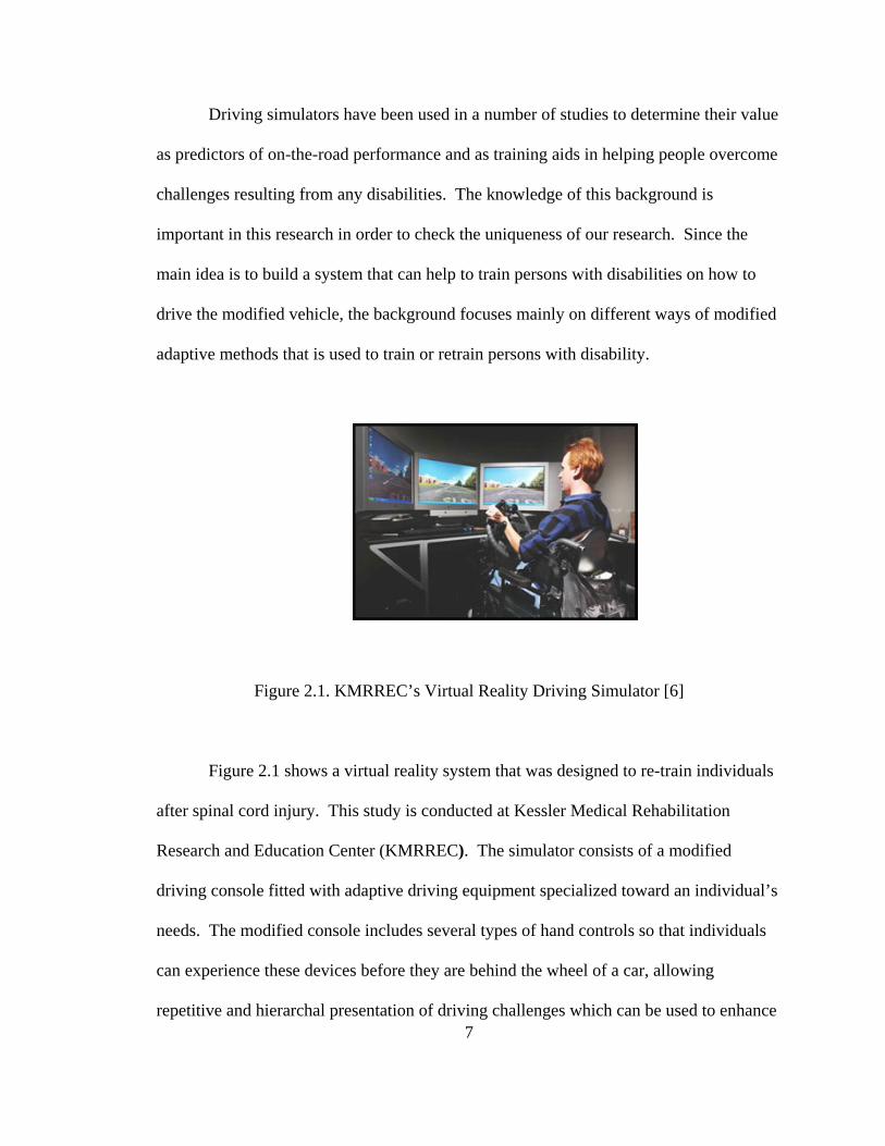
Figure 2.1. KMRREC’s Virtual Reality Driving Simulator [6]
7
Figure 2.1 shows a virtual reality system that was designed to re-train individuals
after spinal cord injury. This study is conducted at Kessler Medical Rehabilitation
Research and Education Center (KMRREC). The simulator consists of a modified
driving console fitted with adaptive driving equipment specialized toward an individual’s
needs. The modified console includes several types of hand controls so that individuals
can experience these devices before they are behind the wheel of a car, allowing
repetitive and hierarchal presentation of driving challenges which can be used to enhance
driving ability and confidence. The hardware for the simulator was designed to provide a
realistic driving interface, and includes a real steering wheel and adaptive equipment
including hand controls (gas and brake), steering wheel knobs, tri-pin. The system is
fully adjustable, i.e. height, tilt, and telescope, for control to provide a comfortable
interface for most wheelchair configurations. The system can deliver a variety of virtual
driving environments and conditions [6].
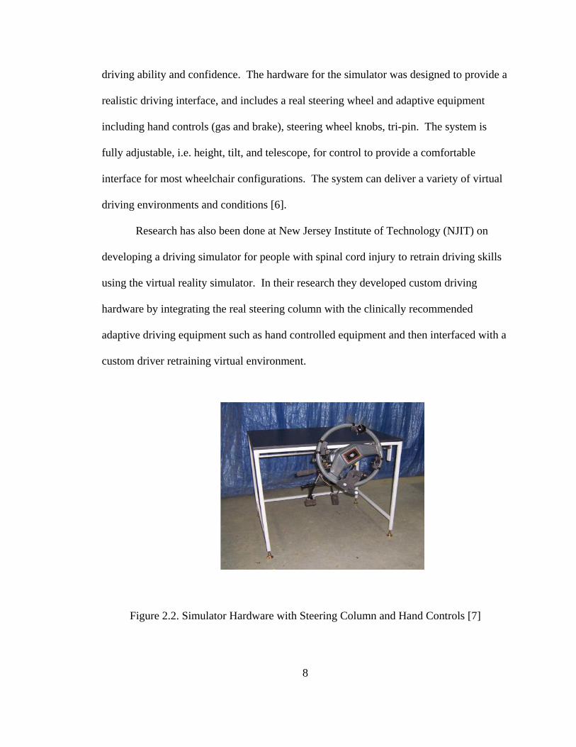
Research has also been done at New Jersey Institute of Technology (NJIT) on
developing a driving simulator for people with spinal cord injury to retrain driving skills
using the virtual reality simulator. In their research they developed custom driving
hardware by integrating the real steering column with the clinically recommended
adaptive driving equipment such as hand controlled equipment and then interfaced with a
custom driver retraining virtual environment.
Figure 2.2. Simulator Hardware with Steering Column and Hand Controls [7]
8
As seen in Figure 2.2 NJIT use a hand controller for acceleration and braking system
which is located to the left of the wheel, and a spinner or tri-pin knob located in one of
four quadrants on the wheel (upper right, upper left, lower right, or lower left) for turning
the steering wheel [7].
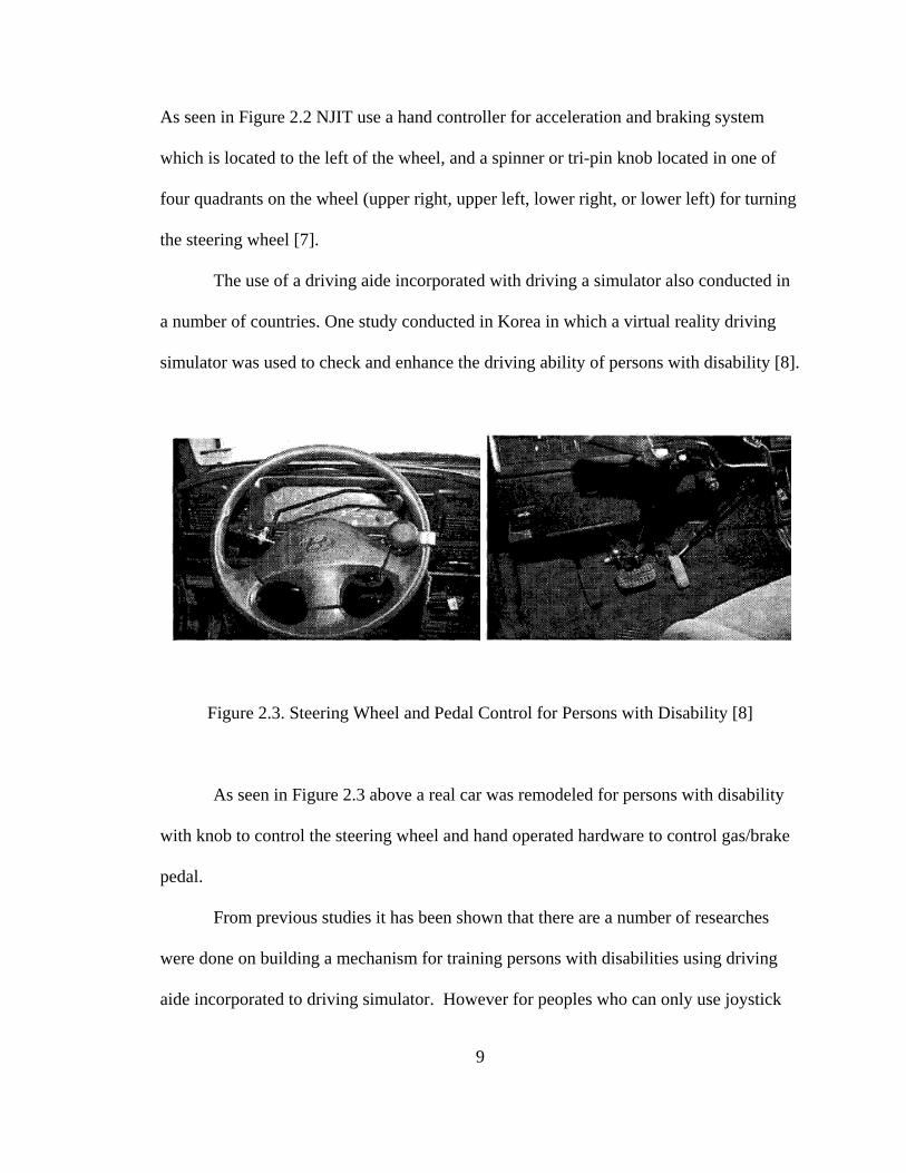
The use of a driving aide incorporated with driving a simulator also conducted in
a number of countries. One study conducted in Korea in which a virtual reality driving
simulator was used to check and enhance the driving ability of persons with disability [8].
Figure 2.3. Steering Wheel and Pedal Control for Persons with Disability [8]
As seen in Figure 2.3 above a real car was remodeled for persons with disability
with knob to control the steering wheel and hand operated hardware to control gas/brake
pedal.
From previous studies it has been shown that there are a number of researches
were done on building a mechanism for training persons with disabilities using driving
aide incorporated to driving simulator. However for peoples who can only use joystick
9
10
as a means of controlling the steering wheel and gas/brake pedal of the vehicle, such
instrument was not developed as a means of training. As a result it is considered that
building a system that incorporates both driving simulator and driving aide to operate the
primary control via joystick would be important for research. As the primary control of
the vehicle controls the steering and gas/brake pedal of the vehicle, the joystick operated
primary control differs from the other means, as mentioned above, of controlling the
primary control. That is when a person with disability uses joystick only one input, i.e.
the joystick, is used to control both parts of the primary control and this could be harder
to control as compared to a primary control that operated by hand for controlling
gas/brake pedal and knob or tri-pin for steering.
2.3. Disabilities
Different kinds of disabilities affect people in different ways. Disability can
become a fact of life for anyone at any time. Today, 54 million people in the United
States are living in the community with a disability. That’s one in every five people.
According to the most recent census data, around 52 million of them live in their
community (U.S. Census Bureau 2002). Additionally, about 2 million live in nursing
homes and other long-term care facilities. Some people are born with a disability; some
people get sick or have an accident that results in a disability; and some people develop a
disability as they age. The reality is that just about everyone; women, men and children
of all ages, races and ethnicities; will experience a disability some time during his or her
lifetime. As we age, the likelihood of having a disability of some kind increases. For
example, 22.6 percent of 45 to 54 year olds have some form of disability; 44.9 percent of
11
65 to 69 year olds have some form of disability; and 73.6 percent of those 80 years and
older have some form of disability [9].
Disabilities were classified in one of three domains: communication, physical, or
mental. Responses to several questions were used to arrive at the overall measures of
each domain. About 26.0 million people had disabilities in one domain (communication:
2.7 million; physical: 18.9 million; mental: 4.4 million); 14.2 million people had
disabilities in two domains (communication and physical: 7.8 million; communication
and mental: 651,000; physical and mental: 5.8 million); and 4.4 million people had
disabilities in all three domains [10].
2.4. Rehabilitation Engineering and Assistive Technology
Rehabilitation engineering is a people-oriented field, more than most fields of
engineering [11]. It is the application of science and technology to ameliorate the
handicaps of individuals with disability. Various terms have been used to describe this
sphere of activity, including prosthetics/orthotics, assistive technology, assistive device
design, rehabilitation technology, and even biomedical engineering applied to disability.
[12].
In contrast, an assistive device is a tool or implement that makes a particular
function easier or possible to perform. An assistive device may be as simple as an
electric toothbrush, or as elaborate as an environmental control system that persons who
have lost the use of their limbs can operate with a mouth switch [11]. One widely used
definition for assistive technology is found in Public Law 100-407. It defines assistive
technology as “any item, piece of equipment or product system whether acquired
12
commercially off the shelf, modified or customized that is used to increase or improve
functional capabilities of individuals with disabilities” [13].
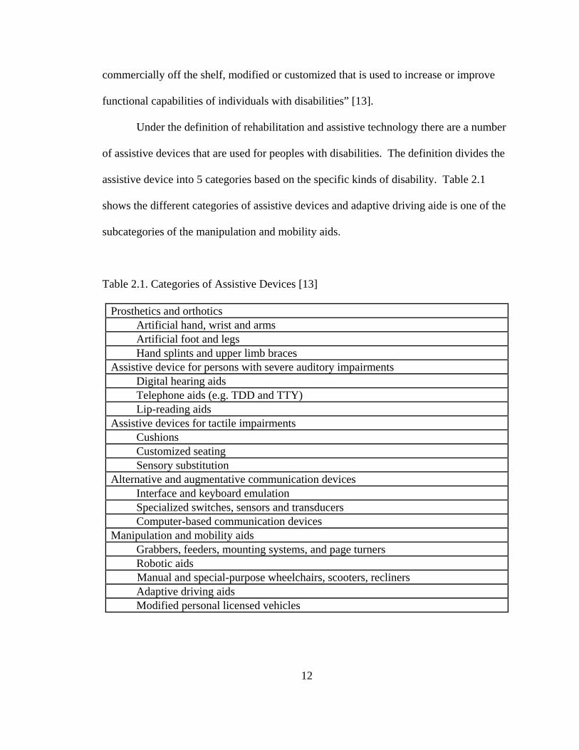
Under the definition of rehabilitation and assistive technology there are a number
of assistive devices that are used for peoples with disabilities. The definition divides the
assistive device into 5 categories based on the specific kinds of disability. Table 2.1
shows the different categories of assistive devices and adaptive driving aide is one of the
subcategories of the manipulation and mobility aids.
Table 2.1. Categories of Assistive Devices [13]
Prosthetics and orthotics Artificial hand, wrist and arms Artificial foot and legs Hand splints and upper limb braces Assistive device for persons with severe auditory impairments Digital hearing aids Telephone aids (e.g. TDD and TTY) Lip-reading aids Assistive devices for tactile impairments Cushions Customized seating Sensory substitution Alternative and augmentative communication devices Interface and keyboard emulation Specialized switches, sensors and transducers Computer-based communication devices Manipulation and mobility aids Grabbers, feeders, mounting systems, and page turners Robotic aids Manual and special-purpose wheelchairs, scooters, recliners Adaptive driving aids Modified personal licensed vehicles
13
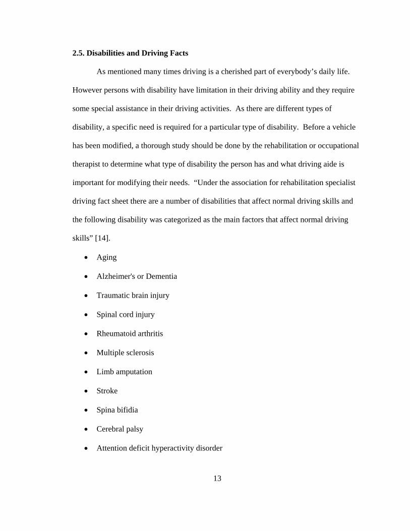
2.5. Disabilities and Driving Facts
As mentioned many times driving is a cherished part of everybody’s daily life.
However persons with disability have limitation in their driving ability and they require
some special assistance in their driving activities. As there are different types of
disability, a specific need is required for a particular type of disability. Before a vehicle
has been modified, a thorough study should be done by the rehabilitation or occupational
therapist to determine what type of disability the person has and what driving aide is
important for modifying their needs. “Under the association for rehabilitation specialist
driving fact sheet there are a number of disabilities that affect normal driving skills and
the following disability was categorized as the main factors that affect normal driving
skills” [14].
• Aging
• Alzheimer's or Dementia
• Traumatic brain injury
• Spinal cord injury
• Rheumatoid arthritis
• Multiple sclerosis
• Limb amputation
• Stroke
• Spina bifidia
• Cerebral palsy
• Attention deficit hyperactivity disorder
14
Out of theses main categories spinal cord injury, rheumatoid arthritis, and limb
amputation were the main disability that requires the use of joystick modification. For
this research these are the targeted populations. However, it is important to have a better
understanding of all the main factors of disabilities and its effect on driving facts in order
to develop the proper driving aide for a specific population. For this reason a detailed
discussion is referenced in Appendix D.
After a spinal cord injury has occurred, a person is no longer able to drive an
automobile in the normal manner. However, there are several types of adaptive
equipment and vehicle modifications that can allow an individual with a spinal cord
injury to drive. Similarly due to rheumatoid arthritis there occur a loss of joint mobility
that result in lack of ability to reach, manipulate, and release objects. More extensive
adaptive equipment or vehicle modifications may be needed for persons whose ability to
use their arms and legs is severely affected by a disability. So for these types of disability
a choice of adaptive modification for their vehicle is important based on their specific
needs. However if the person seems to be highly disabled the use of joystick is important
as a means of modification their vehicles.
It is also hard to drive an automobile in the normal manner for persons with limb
amputation. There are, however, several types of adaptive devices that can allow an
individual with an amputation to safely continue driving. The site of amputation(s) will
determine the degree of difficulty an amputee will have with driving a standard equipped
vehicle. In most cases, the adapted equipment will involve compensation for the inability
to reach and operate primary and secondary driving controls [14]. Person with specific
type of amputation their vehicle is adapted on their specific needs. Even though there are
15
different kinds of amputee, such as right leg, left leg and upper extremity amputee,
joystick is mostly important for person with triple or quadruple amputation as it is hard
for them to operate the primary control of the vehicle safely as needed as compared to the
other amputee.
Discussing the background about different types of training methods for disability
helps the research to focus on other kinds of disabilities, such as tetraplegic or paraplegic,
and try to find out other means of training method for driving a modified vehicle. This
background shapes the research to build a joystick enabled system by integrating the
driving aid and driving simulator that are not available as a means of training for persons
with disability. The knowledge of different kinds of disability and its number is
important for the research. As there are different kinds of disability it is good to know
the type of disability that needs specific modification on their vehicle and especially with
joystick operated driving aide vehicle. Knowing different kinds of disability and its
driving facts shapes the research to focus on specific kinds of disability types, such as
spinal cord injury, arthritis and amputation, as these disabilities influence the normal use
of primary control of the vehicle as mentioned previously.
16
Chapter 3
Adaptive Driving Modifications for Persons with Physical Limitation
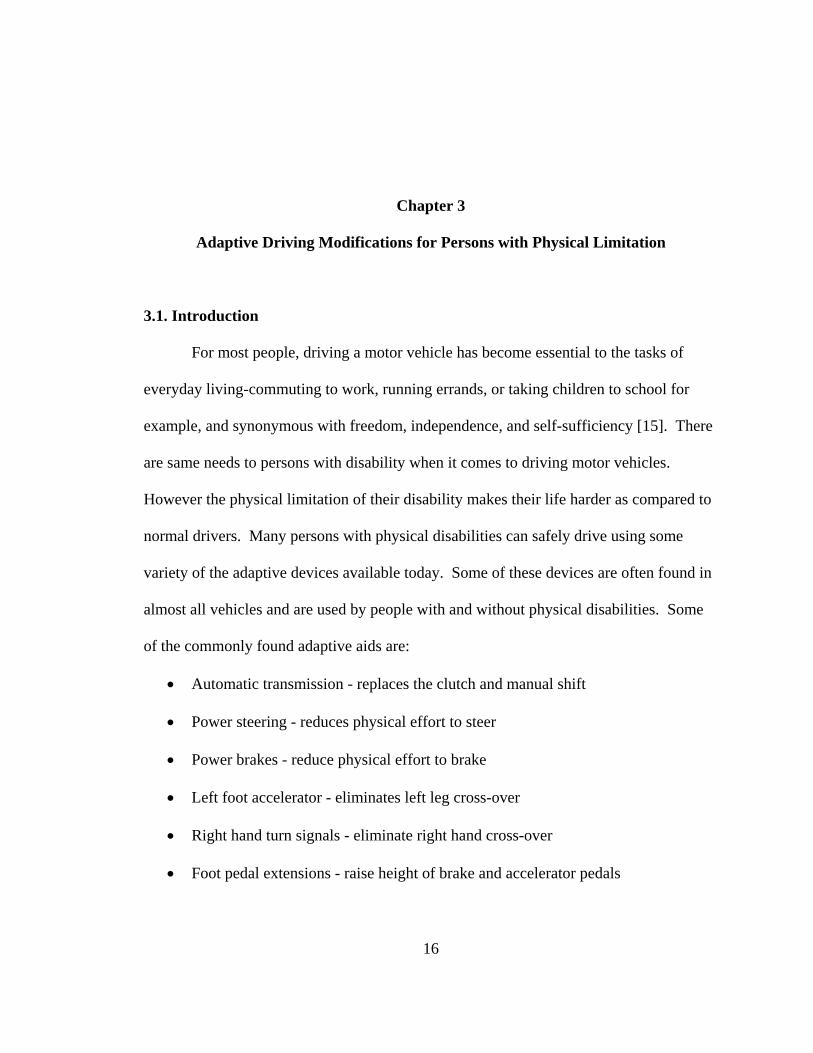
3.1. Introduction
For most people, driving a motor vehicle has become essential to the tasks of
everyday living-commuting to work, running errands, or taking children to school for
example, and synonymous with freedom, independence, and self-sufficiency [15]. There
are same needs to persons with disability when it comes to driving motor vehicles.
However the physical limitation of their disability makes their life harder as compared to
normal drivers. Many persons with physical disabilities can safely drive using some
variety of the adaptive devices available today. Some of these devices are often found in
almost all vehicles and are used by people with and without physical disabilities. Some
of the commonly found adaptive aids are:
• Automatic transmission - replaces the clutch and manual shift
• Power steering - reduces physical effort to steer
• Power brakes - reduce physical effort to brake
• Left foot accelerator - eliminates left leg cross-over
• Right hand turn signals - eliminate right hand cross-over
• Foot pedal extensions - raise height of brake and accelerator pedals
17
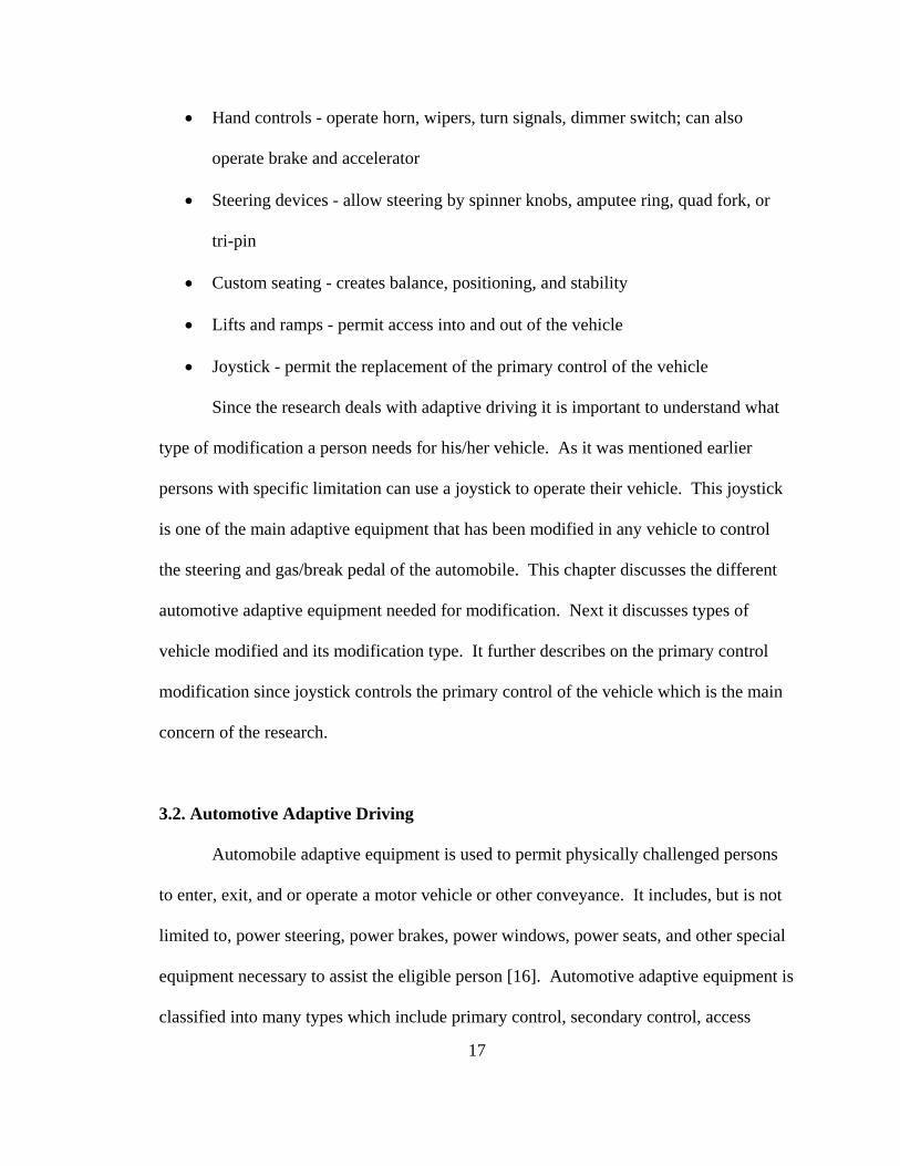
• Hand controls - operate horn, wipers, turn signals, dimmer switch; can also
operate brake and accelerator
• Steering devices - allow steering by spinner knobs, amputee ring, quad fork, or
tri-pin
• Custom seating - creates balance, positioning, and stability
• Lifts and ramps - permit access into and out of the vehicle
• Joystick - permit the replacement of the primary control of the vehicle
Since the research deals with adaptive driving it is important to understand what
type of modification a person needs for his/her vehicle. As it was mentioned earlier
persons with specific limitation can use a joystick to operate their vehicle. This joystick
is one of the main adaptive equipment that has been modified in any vehicle to control
the steering and gas/break pedal of the automobile. This chapter discusses the different
automotive adaptive equipment needed for modification. Next it discusses types of
vehicle modified and its modification type. It further describes on the primary control
modification since joystick controls the primary control of the vehicle which is the main
concern of the research.
3.2. Automotive Adaptive Driving
Automobile adaptive equipment is used to permit physically challenged persons
to enter, exit, and or operate a motor vehicle or other conveyance. It includes, but is not
limited to, power steering, power brakes, power windows, power seats, and other special
equipment necessary to assist the eligible person [16]. Automotive adaptive equipment is
classified into many types which include primary control, secondary control, access
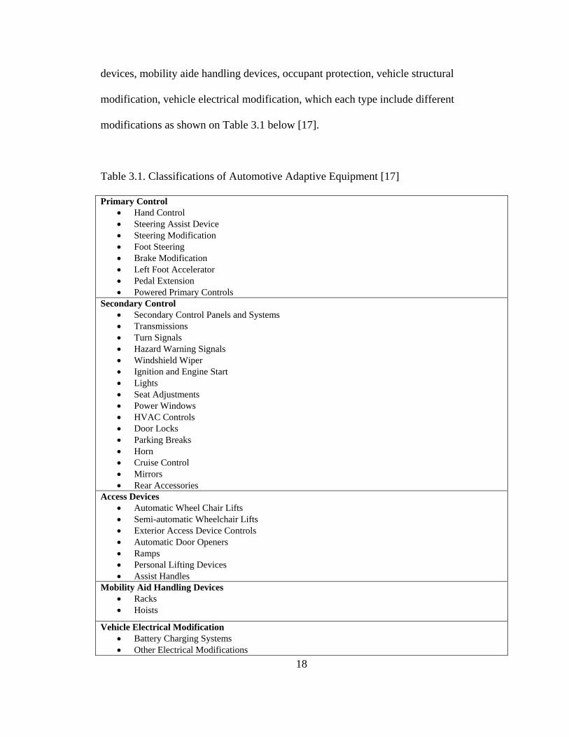
18
devices, mobility aide handling devices, occupant protection, vehicle structural
modification, vehicle electrical modification, which each type include different
modifications as shown on Table 3.1 below [17].
Table 3.1. Classifications of Automotive Adaptive Equipment [17]
Primary Control • Hand Control • Steering Assist Device • Steering Modification • Foot Steering • Brake Modification • Left Foot Accelerator • Pedal Extension • Powered Primary Controls
Secondary Control • Secondary Control Panels and Systems • Transmissions • Turn Signals • Hazard Warning Signals • Windshield Wiper • Ignition and Engine Start • Lights • Seat Adjustments • Power Windows • HVAC Controls • Door Locks • Parking Breaks • Horn • Cruise Control • Mirrors • Rear Accessories
Access Devices • Automatic Wheel Chair Lifts • Semi-automatic Wheelchair Lifts • Exterior Access Device Controls • Automatic Door Openers • Ramps • Personal Lifting Devices • Assist Handles
Mobility Aid Handling Devices • Racks • Hoists
Vehicle Electrical Modification • Battery Charging Systems • Other Electrical Modifications
19
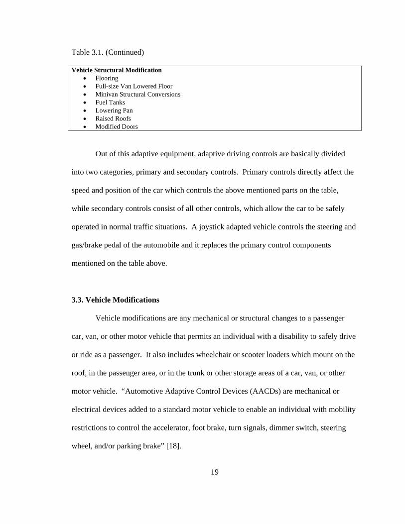
Table 3.1. (Continued) Vehicle Structural Modification
• Flooring • Full-size Van Lowered Floor • Minivan Structural Conversions • Fuel Tanks • Lowering Pan • Raised Roofs • Modified Doors
Out of this adaptive equipment, adaptive driving controls are basically divided
into two categories, primary and secondary controls. Primary controls directly affect the
speed and position of the car which controls the above mentioned parts on the table,
while secondary controls consist of all other controls, which allow the car to be safely
operated in normal traffic situations. A joystick adapted vehicle controls the steering and
gas/brake pedal of the automobile and it replaces the primary control components
mentioned on the table above.
3.3. Vehicle Modifications
Vehicle modifications are any mechanical or structural changes to a passenger
car, van, or other motor vehicle that permits an individual with a disability to safely drive
or ride as a passenger. It also includes wheelchair or scooter loaders which mount on the
roof, in the passenger area, or in the trunk or other storage areas of a car, van, or other
motor vehicle. “Automotive Adaptive Control Devices (AACDs) are mechanical or
electrical devices added to a standard motor vehicle to enable an individual with mobility
restrictions to control the accelerator, foot brake, turn signals, dimmer switch, steering
wheel, and/or parking brake” [18].
20
Many people with disabilities need specific types of modifications or adaptive
equipment added to their motor vehicles to meet their transportation needs. As the
technology has improved in quality and availability, the number of persons using adapted
vehicles has also increased. The 1990 National Health Interview Survey (NHIS-D)
estimated 299,000 adaptive equipment users, while the 1and 1995 NHIS-D estimated
510,000, an increase of 211,000 users over a five-year period [19].
In December of 1997, the National Highway Traffic Safety Administration
(NHTSA) estimated the number of vehicles modified for those with disabilities to be
383,000. The number of vehicles with adaptive equipment is expected to continue to
increase as the U.S. population ages and as access to employment, travel, and recreation
continues to improve for persons with disabilities, as a result of the ADA [19].
From the data collected out of 398 questionnaires the majority (293 or 74 percent)
of respondents over the six year period from 1997 to 2003 were drivers of adapted
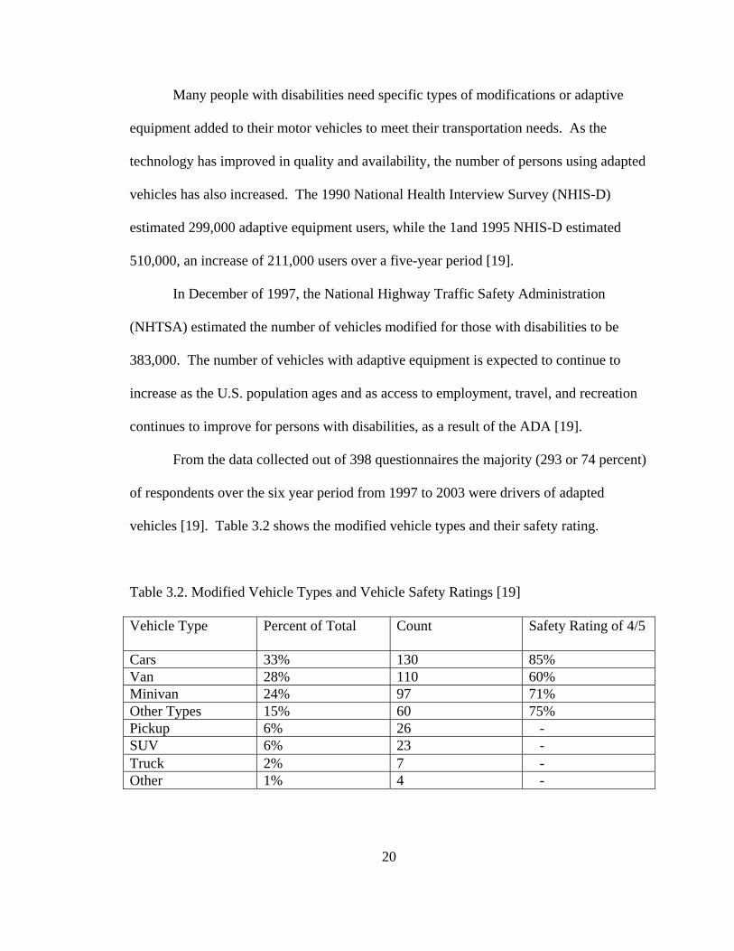
vehicles [19]. Table 3.2 shows the modified vehicle types and their safety rating.
Table 3.2. Modified Vehicle Types and Vehicle Safety Ratings [19] Vehicle Type Percent of Total Count Safety Rating of 4/5
Cars 33% 130 85% Van 28% 110 60% Minivan 24% 97 71% Other Types 15% 60 75% Pickup 6% 26 - SUV 6% 23 - Truck 2% 7 - Other 1% 4 -
21
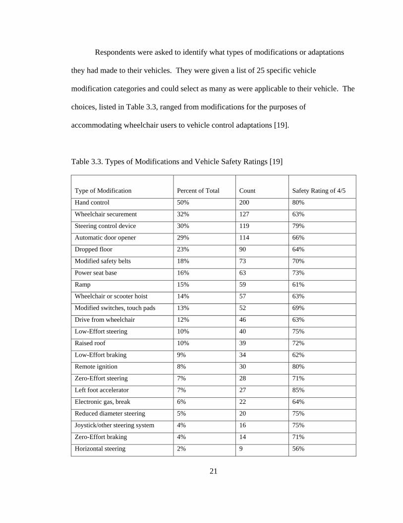
Respondents were asked to identify what types of modifications or adaptations
they had made to their vehicles. They were given a list of 25 specific vehicle
modification categories and could select as many as were applicable to their vehicle. The
choices, listed in Table 3.3, ranged from modifications for the purposes of
accommodating wheelchair users to vehicle control adaptations [19].
Table 3.3. Types of Modifications and Vehicle Safety Ratings [19]
Type of Modification
Percent of Total
Count
Safety Rating of 4/5
Hand control 50% 200 80%
Wheelchair securement 32% 127 63%
Steering control device 30% 119 79%
Automatic door opener 29% 114 66%
Dropped floor 23% 90 64%
Modified safety belts 18% 73 70%
Power seat base 16% 63 73%
Ramp 15% 59 61%
Wheelchair or scooter hoist 14% 57 63%
Modified switches, touch pads 13% 52 69%
Drive from wheelchair 12% 46 63%
Low-Effort steering 10% 40 75%
Raised roof 10% 39 72%
Low-Effort braking 9% 34 62%
Remote ignition 8% 30 80%
Zero-Effort steering 7% 28 71%
Left foot accelerator 7% 27 85%
Electronic gas, break 6% 22 64%
Reduced diameter steering 5% 20 75%
Joystick/other steering system 4% 16 75%
Zero-Effort braking 4% 14 71%
Horizontal steering 2% 9 56%
22
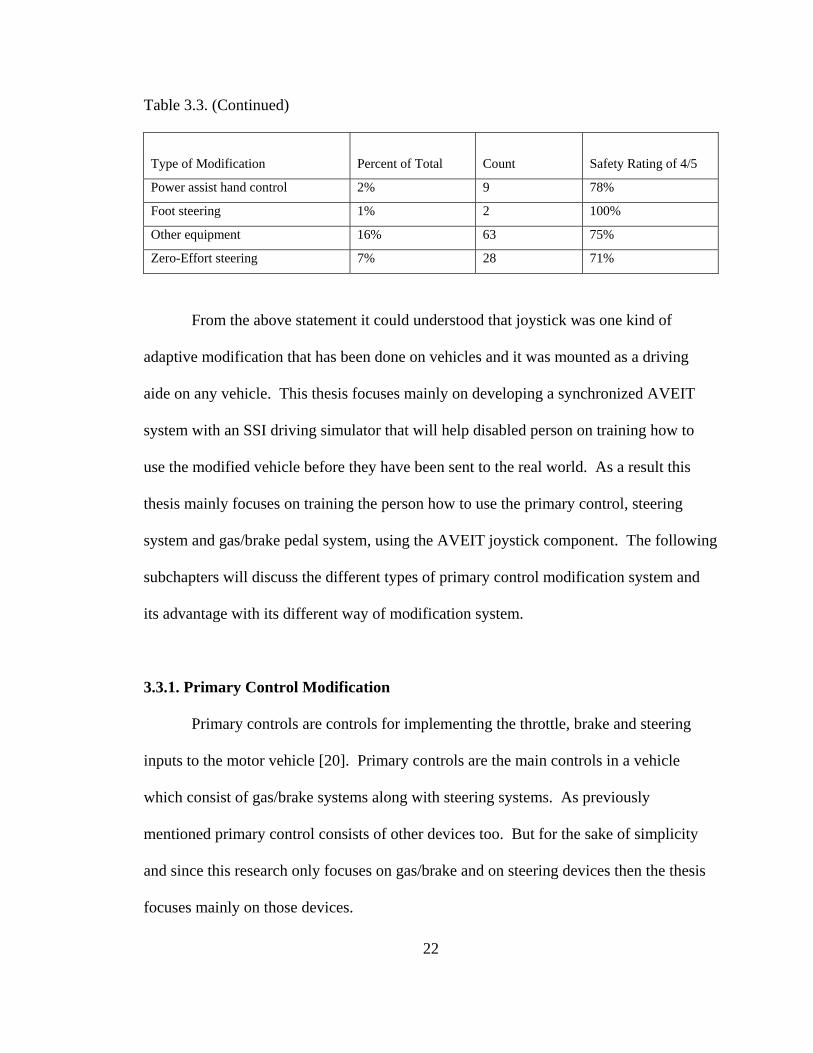
Table 3.3. (Continued)
Type of Modification
Percent of Total
Count
Safety Rating of 4/5
Power assist hand control 2% 9 78%
Foot steering 1% 2 100%
Other equipment 16% 63 75%
Zero-Effort steering 7% 28 71%
From the above statement it could understood that joystick was one kind of
adaptive modification that has been done on vehicles and it was mounted as a driving
aide on any vehicle. This thesis focuses mainly on developing a synchronized AVEIT
system with an SSI driving simulator that will help disabled person on training how to
use the modified vehicle before they have been sent to the real world. As a result this
thesis mainly focuses on training the person how to use the primary control, steering
system and gas/brake pedal system, using the AVEIT joystick component. The following
subchapters will discuss the different types of primary control modification system and
its advantage with its different way of modification system.
3.3.1. Primary Control Modification
Primary controls are controls for implementing the throttle, brake and steering
inputs to the motor vehicle [20]. Primary controls are the main controls in a vehicle
which consist of gas/brake systems along with steering systems. As previously
mentioned primary control consists of other devices too. But for the sake of simplicity
and since this research only focuses on gas/brake and on steering devices then the thesis
focuses mainly on those devices.
23
3.3.1.1. Steering Wheel Aid Modification
Steering wheel aid modification is one of the main modifications applied on
vehicles. It helps to control the factory manufactured wheel by installing some important
parts on either four quadrant of the wheel based on the users need. This modification can
either be removable or fixed. The steering wheel aid can take the form of a knob or an
adaptor to connect the hand, wrist or arm of a disabled person to the steering wheel or
sometimes use a joystick for person who has a paraplegic or tetraplegic disability.
It is generally intended to allow single-handed operation of the steering wheel.
However, those with restricted use of their hand or those with some parts of their arm
missing will require some degree of manipulating of the steering wheel aid. An assessor
of an adaptation should check that the adaptation conforms to the objectives and
specifications stated by the aid manufacturer [21]. To enhance the usefulness of the
adaptation it is advisable that it can be adjusted or fitted with different configurations of
grips to meet the needs of people with different types of disability e.g. shape, size and
axis angle, etc. For those unable to grip a knob, an adaptor can be provided to attach the
hand, wrist or arm of the disabled person to the steering wheel aid or sometimes if the
person has severe disability the vehicle can be modified with joystick capable driving
aide which includes:
• Back-Up Steering System: provides emergency power steering in the event the
factory-installed power steering system fails due to engine failure, power steering
pump failure, broken power steering belt, or ruptured lines. The back-up system
activates instantaneously when the steering fails and allows the driver to steer the
24
vehicle out of traffic. The back-up system can be operated with or without
reduced-effort steering modifications and is available for most vehicles.
• Foot Steering: is a car steering device designed for individuals with limited or no
use of the hands and arms. This special floor-mounted device is intended to
afford complete steering capability with the foot.
• Horizontal Steering: is a horizontal steering column manufacturer recommended
for drivers with limited reach and strength capabilities. The system utilizes a
level-planed steering wheel as opposed to the conventional vertical-planed
steering wheel that is extended over the driver's lap.
• Zero-Effort Steering Modifications: are sensitized steering components designed
to enable drivers with hand and/or arm weakness to steer a vehicle by reducing
the effort needed. Approximately 450 to 500 in. oz. of torque are needed to
control standard factory installed power steering. These modifications are
intended to reduce that effort to less than 50 in. oz. of torque [22].
3.3.1.2. Gas and Brake Modification
Most of the procedures and restrictions that apply to gas/brake modifications are
similar to the steering modifications. Reduced and zero-effort gas/brake systems are
available in the pneumatic and electronic models. The term reduced-effort braking is
defined as a modification to reduce the effort required to brake the vehicles to a specified
level below that needed for a factory power breaking which is up to 112 lbs [21].
Reduced-effort brake is one of the two types: Low-effort and zero-effort braking which
its modifications include:
25
• Zero-Effort Braking Modification: is sensitized brake modifications designed to
enable drivers with little strength in their hands and/or arms.
• Back-Up Brake System: is an emergency braking system designed for drivers
with hand and/or arm weakness to break the vehicle in the event the factory-
installed power brakes fail due to engine failure or low vacuum [22].
3.3.2. Joystick Driving Control
The joystick driving control is a one-hand drive control system for steering,
acceleration, and braking control operated with a joystick. The joystick mounts in any
position on the left or right side. Acceleration is achieved by pulling back on the
joystick; braking by pushing forward, and steering with a side-to-side motion [22].
26
Chapter 4
Simulator Systems International and AEVIT Driving Control System
4.1. Introduction
In the last chapter the need for automotive adaptive driving controls was
discussed. I also described some existing adaptive driving controls for the disabled and
how they are incorporated into the driving environment through vehicle modifications.
This chapter describes one such adaptive driving system, which is currently in use for
modified driving by persons with disabilities. It is known as the AEVIT (Advanced
Electronic Vehicle Interface Technology) driving control system manufactured by EMC
(Electronic Mobility Controls), LLC. Also, this chapter provides a description of a
driving simulator which is introduced by Simulator Systems International. It is fully-
interactive driver rehabilitation training and assessment simulator.
The AEVIT driving system and the driving simulator device are connected
through an interface of mechanical parts between the gas/brake servo of the AVEIT
device and the gas/brake pedal of the driving simulator. The steering wheel of the
AVEIT system and the driving simulator also connected mechanically through the use of
motor and a mechanically designed coupler that couples the steering wheels of AVEIT
and SSI system interfaced with electrical device.
27
The intention of this thesis is to obtain a qualitative result of electromechanical
synchronization between the steering wheels of the AVEIT system and that of the driving
simulator and also a mechanical synchronization between the gas/brake servo of the
AVEIT system and gas/brake pedal of the driving simulator. In this chapter the hardware
and software of the AVEIT system and the driving simulator that is important to use in
this research will be discussed.
4.2. The AVEIT Driving System
The AEVIT System (Advanced Electronic Vehicle Interface Technology) is a
product of Electronic Mobility Controls, LLC (EMC). EMC manufactures a variety of
primary driving control options designed to operate the gas, brake and steering controls
of a motor vehicle. It basically combines the primary driving control devices, the DS-
2000 (steering wheel), the EGB (gas/brake), and the DIGIDRIVE (joystick) into one
single control system, AEVIT. The AEVIT system has more than ten input devices
available to meet different user-needs and capabilities, thus making it an easier
alternative for operating the factory installed steering, brake and gas controls [23].
The AEVIT primary driving control system provides a low-effort control solution
for operation of the factory gas, brake, and steering control. Each of the different control
inputs can be used in conjunction with the same control drives and output servomotor.
The two servomotors, one for the device and the other for the steering device, convert the
mechanical input into motion [20].
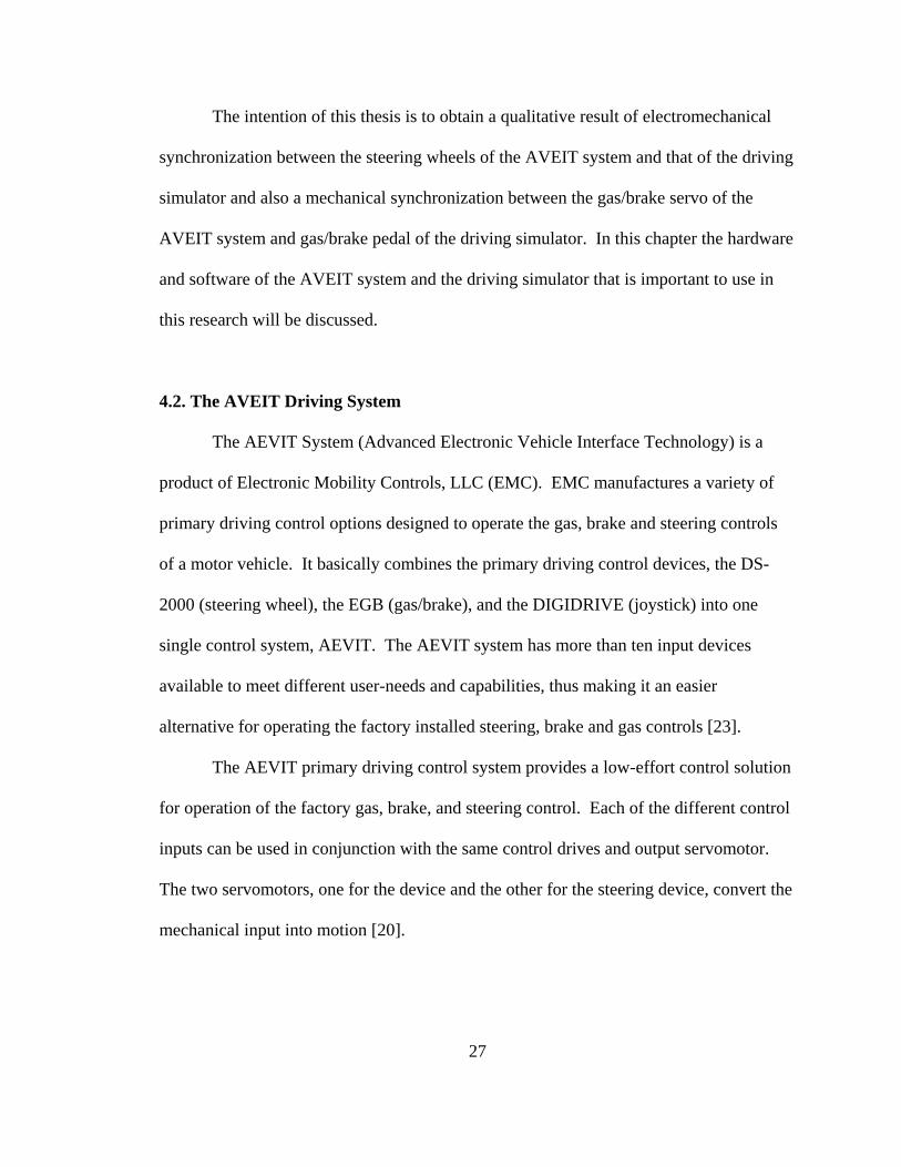
A diagram has been provided to show all of the components of the AEVIT system
and how they connect. Each line below represents a connection and is marked with the
type of information that it carries.
Figure 4.1. AEVIT System Layout [23]
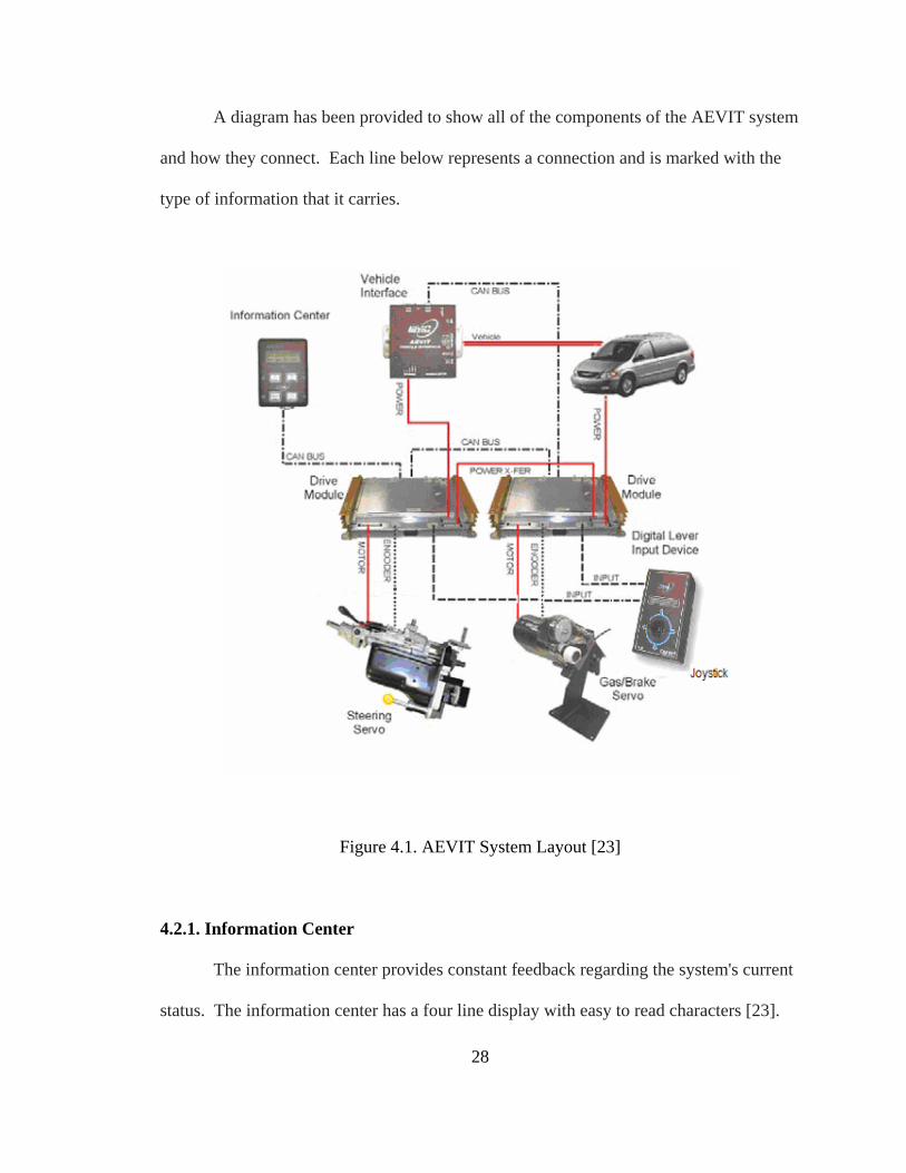
4.2.1. Information Center
The information center provides constant feedback regarding the system's current
status. The information center has a four line display with easy to read characters [23].
28
When the AVEIT driving aide is rebooted, the information center is the one that tells the
exact information weather the primary control is rebooted or not to default position.
Figure 4.2. Information Center [23]
The SCROLL keys are used to move around within a menu. At the end of a
Menu, they will also bring you back to the first screen. These keys are safe to use at all
times. The SELECT key performs two functions. First, it is used to select a processor to
view diagnostic information. Second, it is used to clear any diagnostic information that
may be displayed during normal operation. The OFF (ESC) key is used to boot down
AEVIT after the ignition has been turned OFF. There are two connections on the bottom
of the information center. The Controller Area Network (CAN) bus port is the only port
that will be connected to the AEVIT touchpad [20].
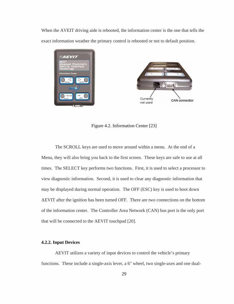
4.2.2. Input Devices
AEVIT utilizes a variety of input devices to control the vehicle’s primary
functions. These include a single-axis lever, a 6" wheel, two single-axes and one dual-
29
axis joysticks, and a wheel/joystick combination. All input devices have three electronic
position sensing components called potentiometers that monitor each controller’s position
at all times. With three components monitoring the same circuit and their respective
input, the system’s safety and reliability is enhanced far beyond that of a system that uses
only one type of sensing device [23]. For this thesis the joystick is the focus.
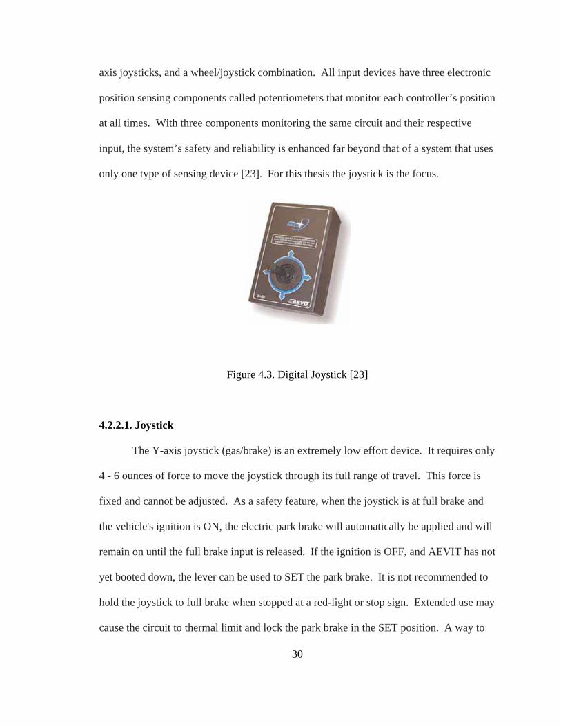
Figure 4.3. Digital Joystick [23]
4.2.2.1. Joystick
The Y-axis joystick (gas/brake) is an extremely low effort device. It requires only
4 - 6 ounces of force to move the joystick through its full range of travel. This force is
fixed and cannot be adjusted. As a safety feature, when the joystick is at full brake and
the vehicle's ignition is ON, the electric park brake will automatically be applied and will
remain on until the full brake input is released. If the ignition is OFF, and AEVIT has not
yet booted down, the lever can be used to SET the park brake. It is not recommended to
hold the joystick to full brake when stopped at a red-light or stop sign. Extended use may
cause the circuit to thermal limit and lock the park brake in the SET position. A way to
30
avoid this is once it comes to a complete stop; ease off the joystick just enough to no
longer activate the park brake, but not enough to allow the vehicle to roll [23].
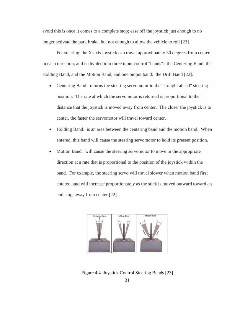
For steering, the X-axis joystick can travel approximately 30 degrees from center
in each direction, and is divided into three input control "bands": the Centering Band, the
Holding Band, and the Motion Band, and one output band: the Drift Band [22].
• Centering Band: returns the steering servomotor to the” straight ahead" steering
position. The rate at which the servomotor is returned is proportional to the
distance that the joystick is moved away from center. The closer the joystick is to
center, the faster the servomotor will travel toward center.
• Holding Band: is an area between the centering band and the motion band. When
entered, this band will cause the steering servomotor to hold its present position.
• Motion Band: will cause the steering servomotor to move in the appropriate
direction at a rate that is proportional to the position of the joystick within the
band. For example, the steering servo will travel slower when motion band first
entered, and will increase proportionately as the stick is moved outward toward an
end stop, away from center [22].
Figure 4.4. Joystick Control Steering Bands [23] 31
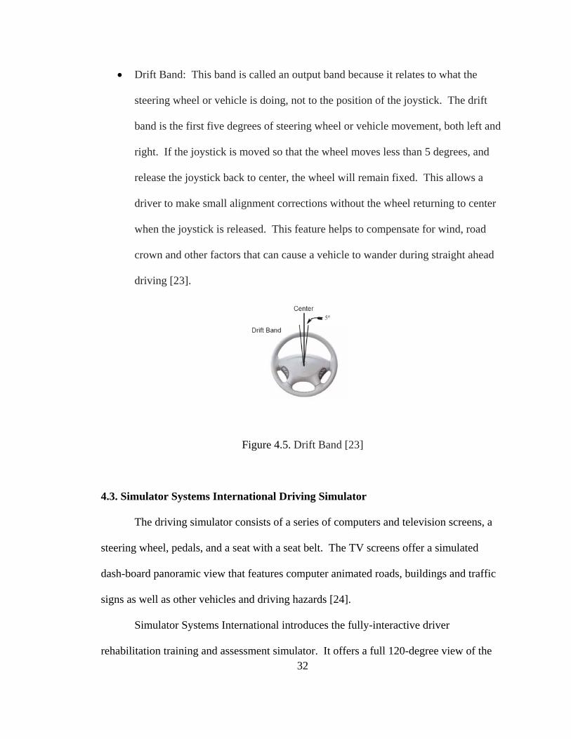
• Drift Band: This band is called an output band because it relates to what the
steering wheel or vehicle is doing, not to the position of the joystick. The drift
band is the first five degrees of steering wheel or vehicle movement, both left and
right. If the joystick is moved so that the wheel moves less than 5 degrees, and
release the joystick back to center, the wheel will remain fixed. This allows a
driver to make small alignment corrections without the wheel returning to center
when the joystick is released. This feature helps to compensate for wind, road
crown and other factors that can cause a vehicle to wander during straight ahead
driving [23].
Figure 4.5. Drift Band [23]
4.3. Simulator Systems International Driving Simulator
The driving simulator consists of a series of computers and television screens, a
steering wheel, pedals, and a seat with a seat belt. The TV screens offer a simulated
dash-board panoramic view that features computer animated roads, buildings and traffic
signs as well as other vehicles and driving hazards [24].
Simulator Systems International introduces the fully-interactive driver
rehabilitation training and assessment simulator. It offers a full 120-degree view of the 32
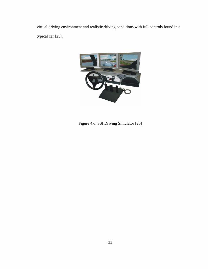
virtual driving environment and realistic driving conditions with full controls found in a
typical car [25].
Figure 4.6. SSI Driving Simulator [25]
33
34
Chapter 5
Electromechanical Design and Synchronization of the Driving Systems
5.1. Introduction
Prior to starting this project a van which is used for the research was bought and
modified to accommodate the research. As a result half of its length was cut and almost
all parts of its motor and the dashboard was removed. In order to move the van easily
wheels were attached to it which makes the van to easily movable around the lab. At the
same time the AVEIT driving aide and SSI driving simulator were also bought for the
purpose of the study.
This chapter begins with modification of the inside of a working van so that it will
be suitable to install or assemble the driving aide and driving simulator for training
persons with disabilities. It explains what methods are used to come up with the
particular kind of design and why the material was selected to hold the driving aide parts.
This chapter also explains how the two driving systems are synchronized together. That
is, it explains the different approaches of mechanical and electrical designs. The
mechanical parts of the design are classified into two parts which include a design for the
AVEIT driving aide and SSI driving simulator couplers. Some other parts such as
bearing, gears and collars were bought from outside vendors to make the mechanical
design to a complete working shape. It also explains the particulars of the design and
35
part of the factors that suit an engineering design. For the electrical part it shows the
circuit diagram and also explains how the systems of the electrical circuit work. When
this design was successfully finished the system was synchronized to show that it is in a
working condition and it is feasible. Finally a test was made to check on whether the
driving aide is working with driving simulator or not and made conclusion based on the
result.
5.2. Van Assembly
As the main idea of the project is to synchronize the driving aide with the driving
simulator and then study the use of this method to train persons with disability how to
drive a motor vehicle, it is necessary to make the virtual reality driving system inside the
van. As a result it was found to be necessary to assemble the entire driving aide, some
driving simulator parts and other necessary parts inside the van. Due to the bulkiness of
the SSI unit the monitor and gas/brake control was the only parts that were assembled but
the SSI console was not assembled inside it. However, the entire AVEIT driving aide
was assembled inside the van. Before the AVEIT driving aide was installed to the van, a
mechanical part to hold the system was built. As a result, detailed dimensions of the
inside of the van were measured and at the same time, the dimensions of all parts of the
driving aide were also measured. Because all the AVEIT driving system has to be built
inside the van, it is necessary to take into consideration the strength of the design that
holds all the parts. As a result before the design was given to machine shop for
machining a stress analysis was performed on the parts. The cost of the parts was also
taken into consideration. A two angle bars of 2”x3”x10” steel metal were used as a side
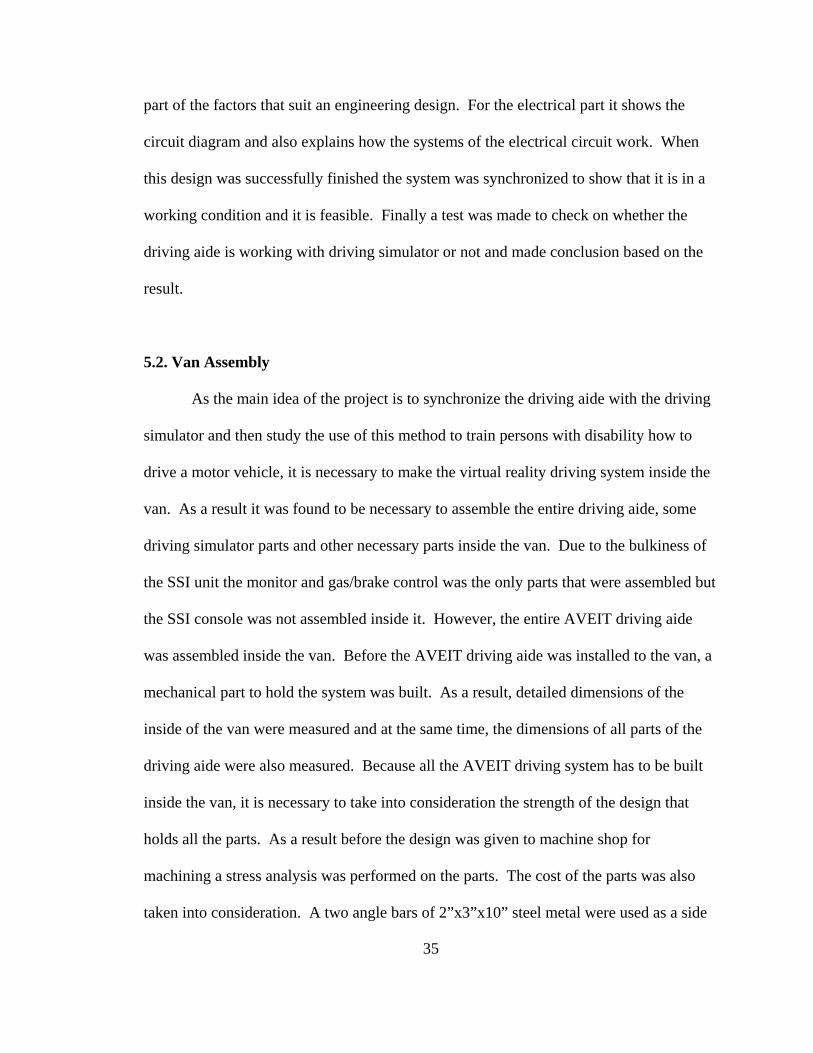
support. These angle bars were mounted on each side of the van. A longitudinal bar of
wood 4”x2”x64” crossed the van and placed on top of the two steel bar.
Figure 5.1. Wood Bar
As shown in Figure 5.1 above the wood bar is crossing the van longitudinally and
placed on top of the steel metal. The wood bar is used to hold the entire driving aide
parts and the monitor. The total weight of the AVEIT driving aide and the monitor of the
driving simulator is approximately 75 lb. The CAD software Solidworks was used to
design the two steel bars. A stress calculation was done on the longitudinal wood bar to
check the strength of the material and ANSYS was also used to check the hand
calculation. The value of stress at any point was calculated using the following formula
where σ =stress, P=Load, x=distance, l=length, b=base, h=height, S=section modulus,
SF=safety factor, Y=yield stress.
36
lSxlxP
**2)(** −
=σ where 6
* 2hbS =
SlP
center *8*
=σ
σY
StressStrengthSF ==
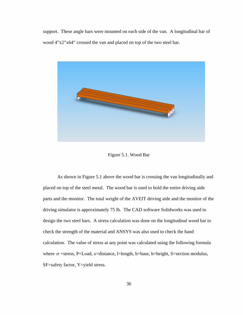
The maximum stress for constant cross section area is located at the center. From
the calculation =maxσ 225 lbf/in2 and the material property Y = 7977 lbf/in2, giving a
safety factor of 35. From this result it can be determined that the design is safe to hold
the material. A stress analysis was done using ANSYS and the maximum stress was
located at the center of the material and it shows the same result as obtained using hand
calculation. Figure 5.2 below shows the maximum bending stress on the bar with a unit
in Megapascal (MPa).
Figure 5.2. Stress Analysis of the Base Holder
37
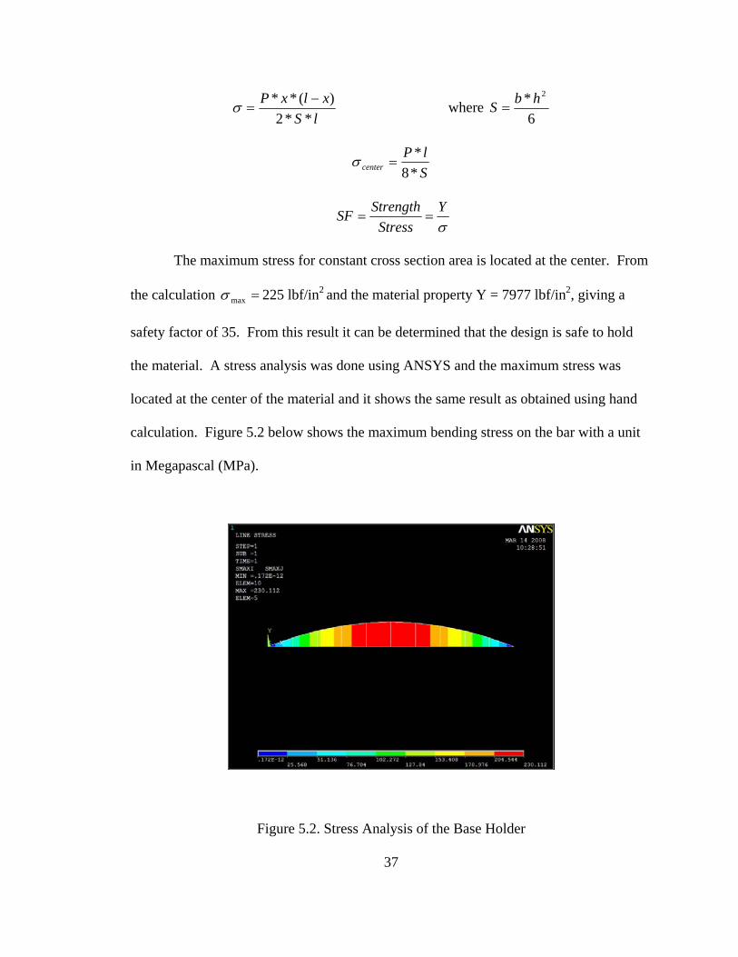
Figure 5.3 is a picture showing the complete assembled AVEIT driving system
and SSI monitor inside the van. The picture was taken from the back of the van and the
front mirror of the van was replaced by the SSI monitor. The idea behind this installation
as shown in the figure below is the driver uses the joystick located to the right of the
steering to rotate the steering. The information center is located to the left of the steering.
So the two main parts of the AVEIT system were mounted on an elongated arm so that it
will be easy as it was extended to the driver. The other parts were placed below the
monitor. Some of the electrical parts of the van were not dismantled as it does not affect
the installations.
Figure 5.3. Assembled Van
38
39
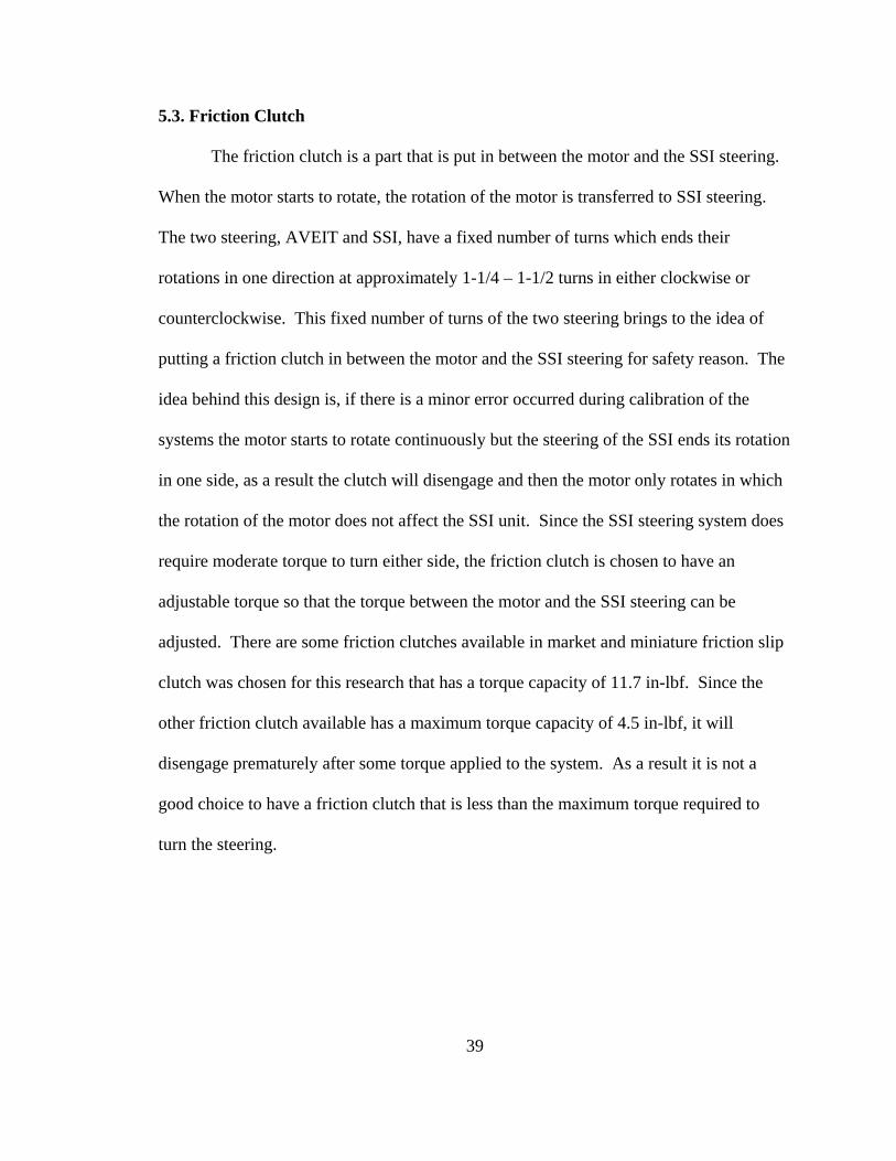
5.3. Friction Clutch
The friction clutch is a part that is put in between the motor and the SSI steering.
When the motor starts to rotate, the rotation of the motor is transferred to SSI steering.
The two steering, AVEIT and SSI, have a fixed number of turns which ends their
rotations in one direction at approximately 1-1/4 – 1-1/2 turns in either clockwise or
counterclockwise. This fixed number of turns of the two steering brings to the idea of
putting a friction clutch in between the motor and the SSI steering for safety reason. The
idea behind this design is, if there is a minor error occurred during calibration of the
systems the motor starts to rotate continuously but the steering of the SSI ends its rotation
in one side, as a result the clutch will disengage and then the motor only rotates in which
the rotation of the motor does not affect the SSI unit. Since the SSI steering system does
require moderate torque to turn either side, the friction clutch is chosen to have an
adjustable torque so that the torque between the motor and the SSI steering can be
adjusted. There are some friction clutches available in market and miniature friction slip
clutch was chosen for this research that has a torque capacity of 11.7 in-lbf. Since the
other friction clutch available has a maximum torque capacity of 4.5 in-lbf, it will
disengage prematurely after some torque applied to the system. As a result it is not a
good choice to have a friction clutch that is less than the maximum torque required to
turn the steering.
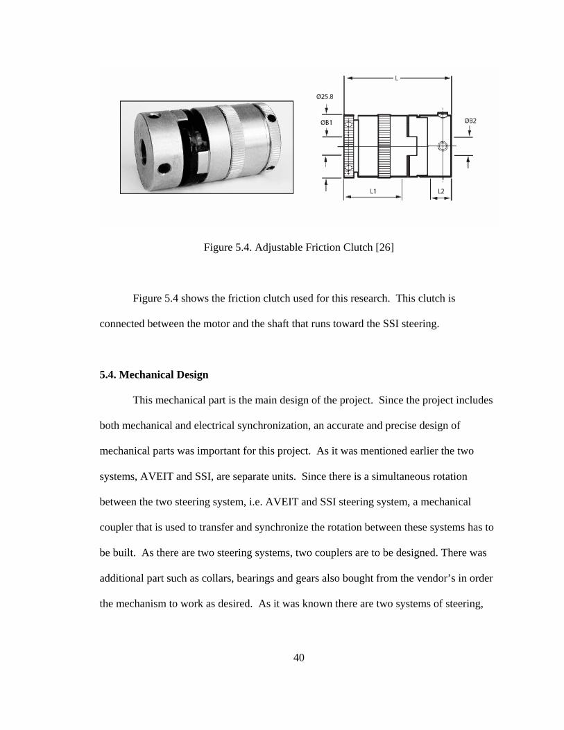
Figure 5.4. Adjustable Friction Clutch [26]
Figure 5.4 shows the friction clutch used for this research. This clutch is
connected between the motor and the shaft that runs toward the SSI steering.
5.4. Mechanical Design
This mechanical part is the main design of the project. Since the project includes
both mechanical and electrical synchronization, an accurate and precise design of
mechanical parts was important for this project. As it was mentioned earlier the two
systems, AVEIT and SSI, are separate units. Since there is a simultaneous rotation
between the two steering system, i.e. AVEIT and SSI steering system, a mechanical
coupler that is used to transfer and synchronize the rotation between these systems has to
be built. As there are two steering systems, two couplers are to be designed. There was
additional part such as collars, bearings and gears also bought from the vendor’s in order
the mechanism to work as desired. As it was known there are two systems of steering,
40

41
hence this mechanical design includes two kinds of coupler design and explains in detail
how it works with the help of figures.
5.4.1. SSI Coupler
The SSI system is located in a separate unit and has a shaft elongated from its
steering. A coupler is build to help all the rotation and that holds all the necessary parts
inside. Since the mechanical part of the coupler attaches the motor and the SSI steering
wheel, the coupler consist of different parts including long shaft, two gears,
potentiometer, and different size of bearings, collars and friction clutch. The coupler is
attached to the motor via friction clutch on one side of the shaft and it has an extension on
the other side attached to the steering of SSI. The shaft is designed in order to fit the
desired dimensions of the bore size of the gears and collars. Since it is the main part that
translates the rotation between the motor and the steering system, the material has to have
an appropriate criterion of engineering design in its strength. As a result the material that
is used for the shaft was chosen to be steel. The shape and size of the shaft was designed
based on the parts that it couples.
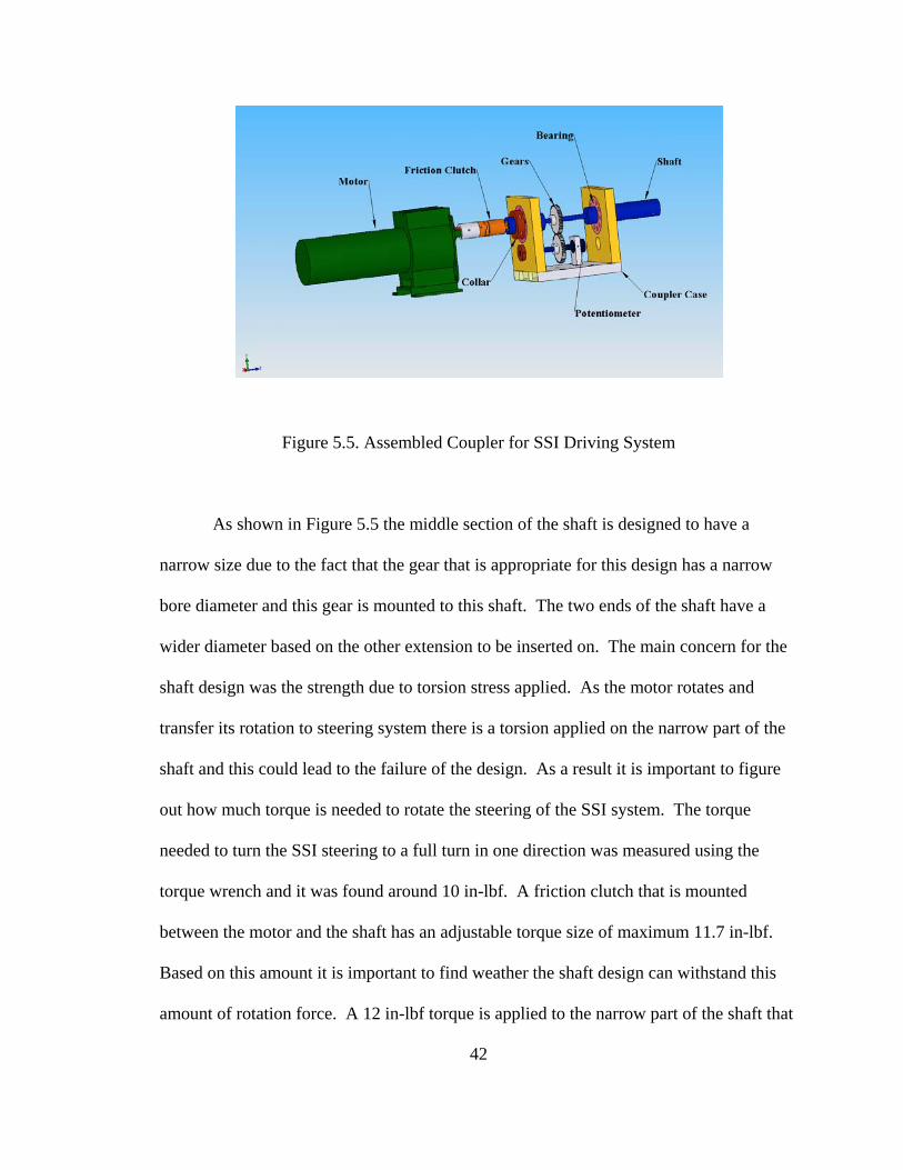
Figure 5.5. Assembled Coupler for SSI Driving System
As shown in Figure 5.5 the middle section of the shaft is designed to have a
narrow size due to the fact that the gear that is appropriate for this design has a narrow
bore diameter and this gear is mounted to this shaft. The two ends of the shaft have a
wider diameter based on the other extension to be inserted on. The main concern for the
shaft design was the strength due to torsion stress applied. As the motor rotates and
transfer its rotation to steering system there is a torsion applied on the narrow part of the
shaft and this could lead to the failure of the design. As a result it is important to figure
out how much torque is needed to rotate the steering of the SSI system. The torque
needed to turn the SSI steering to a full turn in one direction was measured using the
torque wrench and it was found around 10 in-lbf. A friction clutch that is mounted
between the motor and the shaft has an adjustable torque size of maximum 11.7 in-lbf.
Based on this amount it is important to find weather the shaft design can withstand this
amount of rotation force. A 12 in-lbf torque is applied to the narrow part of the shaft that
42
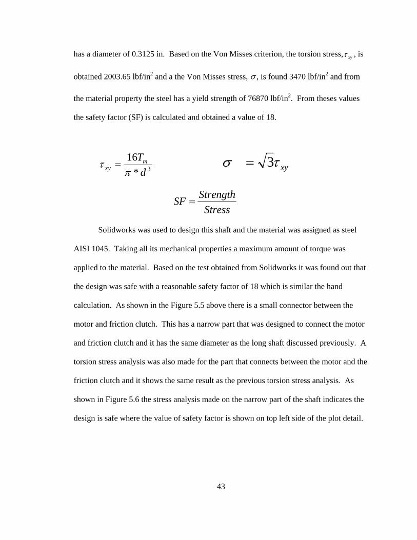
has a diameter of 0.3125 in. Based on the Von Misses criterion, the torsion stress, , is
obtained 2003.65 lbf/in
xyτ
2 and a the Von Misses stress, σ , is found 3470 lbf/in2 and from
the material property the steel has a yield strength of 76870 lbf/in2. From theses values
the safety factor (SF) is calculated and obtained a value of 18.
3*16
dTm
xy πτ = xyτσ 3=
StressStrengthSF =
Solidworks was used to design this shaft and the material was assigned as steel
AISI 1045. Taking all its mechanical properties a maximum amount of torque was
applied to the material. Based on the test obtained from Solidworks it was found out that
the design was safe with a reasonable safety factor of 18 which is similar the hand
calculation. As shown in the Figure 5.5 above there is a small connector between the
motor and friction clutch. This has a narrow part that was designed to connect the motor
and friction clutch and it has the same diameter as the long shaft discussed previously. A
torsion stress analysis was also made for the part that connects between the motor and the
friction clutch and it shows the same result as the previous torsion stress analysis. As
shown in Figure 5.6 the stress analysis made on the narrow part of the shaft indicates the
design is safe where the value of safety factor is shown on top left side of the plot detail.
43
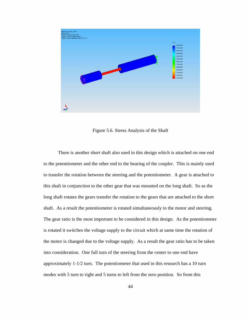
Figure 5.6. Stress Analysis of the Shaft
There is another short shaft also used in this design which is attached on one end
to the potentiometer and the other end to the bearing of the coupler. This is mainly used
to transfer the rotation between the steering and the potentiometer. A gear is attached to
this shaft in conjunction to the other gear that was mounted on the long shaft. So as the
long shaft rotates the gears transfer the rotation to the gears that are attached to the short
shaft. As a result the potentiometer is rotated simultaneously to the motor and steering.
The gear ratio is the most important to be considered in this design. As the potentiometer
is rotated it switches the voltage supply to the circuit which at same time the rotation of
the motor is changed due to the voltage supply. As a result the gear ratio has to be taken
into consideration. One full turn of the steering from the center to one end have
approximately 1-1/2 turn. The potentiometer that used in this research has a 10 turn
modes with 5 turn to right and 5 turns to left from the zero position. So from this
44
45
criterion a 1:1 ratio between the two gears was chosen. This ratio gives to the design so
that no damage will be done on the potentiometer as a result of the rotation of the shafts.
In order to smooth out the rotation, bearings were used on the connection according to its
bore size and at same time to make the shafts in constant position collars are also used.
These gear, bearings and collars were ordered from vendors based on the desired design.
To discuss the operation of this design in short, as the AVEIT steering system rotates, it
initiates the potentiometer and this also initiates the motor to turn due to voltage change.
When the motor turns it rotates the long shaft and the rotation transferred to the steering
of SSI and at same time a gear attached to long shaft also rotates and it transfers the
rotation to the other gear attached to the short shaft. Then the potentiometer rotates until
it is turned off due to voltage change. The electrical process will be explained later on
the electrical system. Figure 5.5 shows the assembled design of the coupler in detail that
is going to be mounted to the SSI steering system.
5.4.2. AVEIT Coupler
This is another mechanical part of the coupler that attached to the steering of the
AVEIT system. Similar to the previous coupler this one also consists of two shafts,
gears, potentiometer, bearings and collars. This coupler is used to transfer the rotation
between the steering and the potentiometer by the help of the gears. The ratio between
the two gears is the most important to take into consideration in this design because it
helps a synchronized transfer of rotation between the steering and that of the
potentiometer. To determine what gear ratio to use in this design, first it is important to
know the one sided full turn of the AVEIT steering from the center or zero degree
46
position. From manufacturer the default AVEIT steering turns almost 1-1/2 to make a
full one side turn. Similarly to the previous one the potentiometer used for this coupler
also has 10 turn model with 5 turn in either side. So from these two factors it is important
to determine what ratio to use for the two gears and from this relationship a factor of 1:1
ratio was chosen.
The long shaft of this mechanism attached or connected on one end only to the
steering servo of the AVEIT system and the short shaft extended inside the coupler and
its one end is attached to potentiometer. The gears are mounted on each shaft. These two
gears are interconnected so that they translate an angular rotation between the steering
servo and the potentiometer. The idea behind this design was when the handicap person
maneuver the joystick by turning either side horizontally, i.e. X-axis, the steering of the
AVEIT rotates with it. So as the long shaft rotates it translates the rotation of the steering
servo to the potentiometer by the help of gears. Then potentiometer will be powered on
the circuit and it changes the voltage supply of the circuit. Since there are no constraints
on this coupler and the unit rotates with insignificant amount of torque, stress calculation
is not of importance for the shaft. Figure 5.7 shows the detailed design of the assembled
coupler.
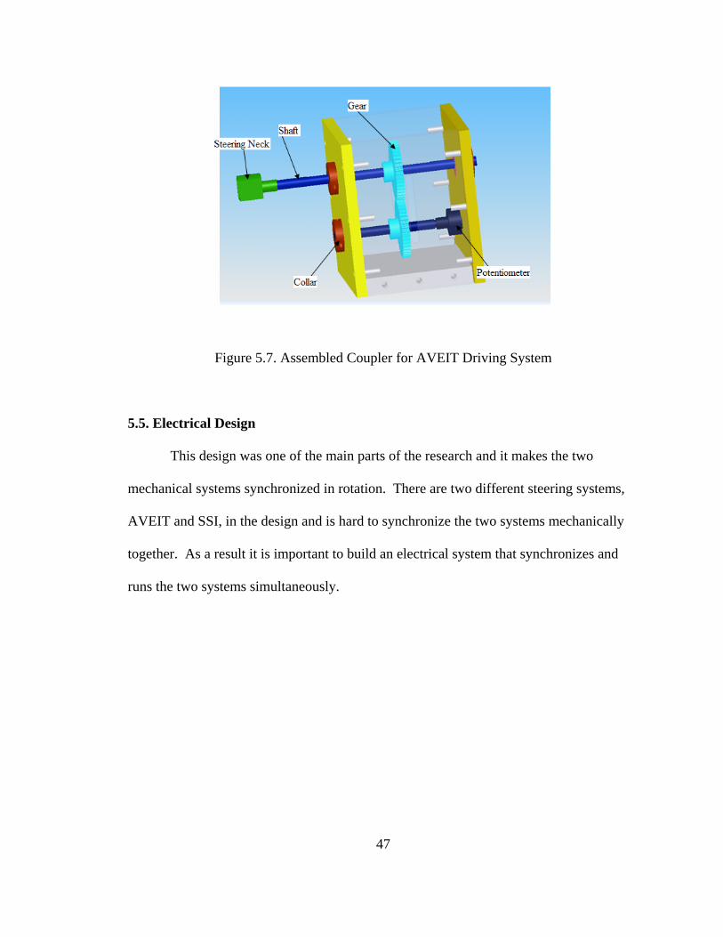
Figure 5.7. Assembled Coupler for AVEIT Driving System
5.5. Electrical Design
This design was one of the main parts of the research and it makes the two
mechanical systems synchronized in rotation. There are two different steering systems,
AVEIT and SSI, in the design and is hard to synchronize the two systems mechanically
together. As a result it is important to build an electrical system that synchronizes and
runs the two systems simultaneously.
47

48
Figure 5.8. Circuit Diagram for Synchronized Rotation
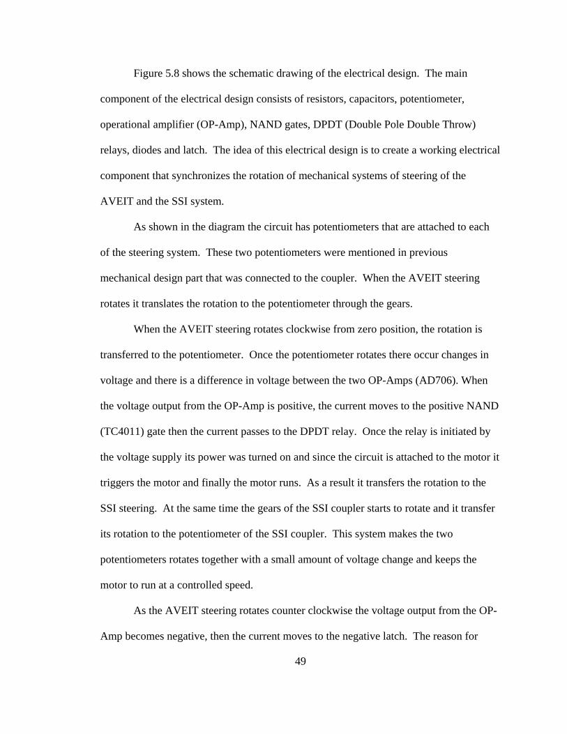
49
Figure 5.8 shows the schematic drawing of the electrical design. The main
component of the electrical design consists of resistors, capacitors, potentiometer,
operational amplifier (OP-Amp), NAND gates, DPDT (Double Pole Double Throw)
relays, diodes and latch. The idea of this electrical design is to create a working electrical
component that synchronizes the rotation of mechanical systems of steering of the
AVEIT and the SSI system.
As shown in the diagram the circuit has potentiometers that are attached to each
of the steering system. These two potentiometers were mentioned in previous
mechanical design part that was connected to the coupler. When the AVEIT steering
rotates it translates the rotation to the potentiometer through the gears.
When the AVEIT steering rotates clockwise from zero position, the rotation is
transferred to the potentiometer. Once the potentiometer rotates there occur changes in
voltage and there is a difference in voltage between the two OP-Amps (AD706). When
the voltage output from the OP-Amp is positive, the current moves to the positive NAND
(TC4011) gate then the current passes to the DPDT relay. Once the relay is initiated by
the voltage supply its power was turned on and since the circuit is attached to the motor it
triggers the motor and finally the motor runs. As a result it transfers the rotation to the
SSI steering. At the same time the gears of the SSI coupler starts to rotate and it transfer
its rotation to the potentiometer of the SSI coupler. This system makes the two
potentiometers rotates together with a small amount of voltage change and keeps the
motor to run at a controlled speed.
As the AVEIT steering rotates counter clockwise the voltage output from the OP-
Amp becomes negative, then the current moves to the negative latch. The reason for
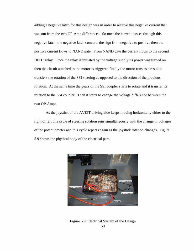
adding a negative latch for this design was in order to receive this negative current that
was out from the two OP-Amp differences. So once the current passes through this
negative latch, the negative latch converts the sign from negative to positive then the
positive current flows to NAND gate. From NAND gate the current flows to the second
DPDT relay. Once the relay is initiated by the voltage supply its power was turned on
then the circuit attached to the motor is triggered finally the motor runs as a result it
transfers the rotation of the SSI steering as opposed to the direction of the previous
rotation. At the same time the gears of the SSI coupler starts to rotate and it transfer its
rotation to the SSI coupler. Then it starts to change the voltage difference between the
two OP-Amps.
As the joystick of the AVEIT driving aide keeps moving horizontally either to the
right or left this cycle of steering rotation runs simultaneously with the change in voltages
of the potentiometer and this cycle repeats again as the joystick rotation changes. Figure
5.9 shows the physical body of the electrical part.
50Figure 5.9. Electrical System of the Design
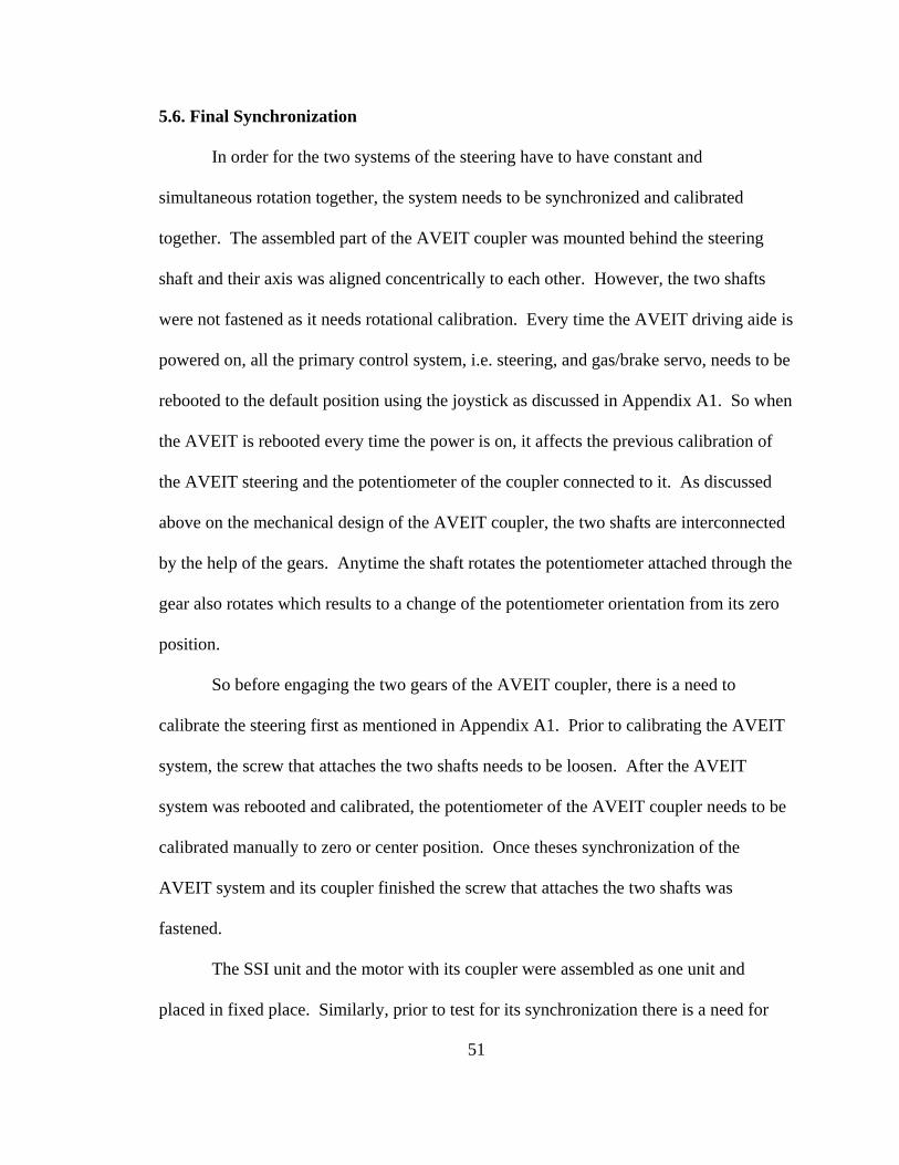
51
5.6. Final Synchronization
In order for the two systems of the steering have to have constant and
simultaneous rotation together, the system needs to be synchronized and calibrated
together. The assembled part of the AVEIT coupler was mounted behind the steering
shaft and their axis was aligned concentrically to each other. However, the two shafts
were not fastened as it needs rotational calibration. Every time the AVEIT driving aide is
powered on, all the primary control system, i.e. steering, and gas/brake servo, needs to be
rebooted to the default position using the joystick as discussed in Appendix A1. So when
the AVEIT is rebooted every time the power is on, it affects the previous calibration of
the AVEIT steering and the potentiometer of the coupler connected to it. As discussed
above on the mechanical design of the AVEIT coupler, the two shafts are interconnected
by the help of the gears. Anytime the shaft rotates the potentiometer attached through the
gear also rotates which results to a change of the potentiometer orientation from its zero
position.
So before engaging the two gears of the AVEIT coupler, there is a need to
calibrate the steering first as mentioned in Appendix A1. Prior to calibrating the AVEIT
system, the screw that attaches the two shafts needs to be loosen. After the AVEIT
system was rebooted and calibrated, the potentiometer of the AVEIT coupler needs to be
calibrated manually to zero or center position. Once theses synchronization of the
AVEIT system and its coupler finished the screw that attaches the two shafts was
fastened.
The SSI unit and the motor with its coupler were assembled as one unit and
placed in fixed place. Similarly, prior to test for its synchronization there is a need for
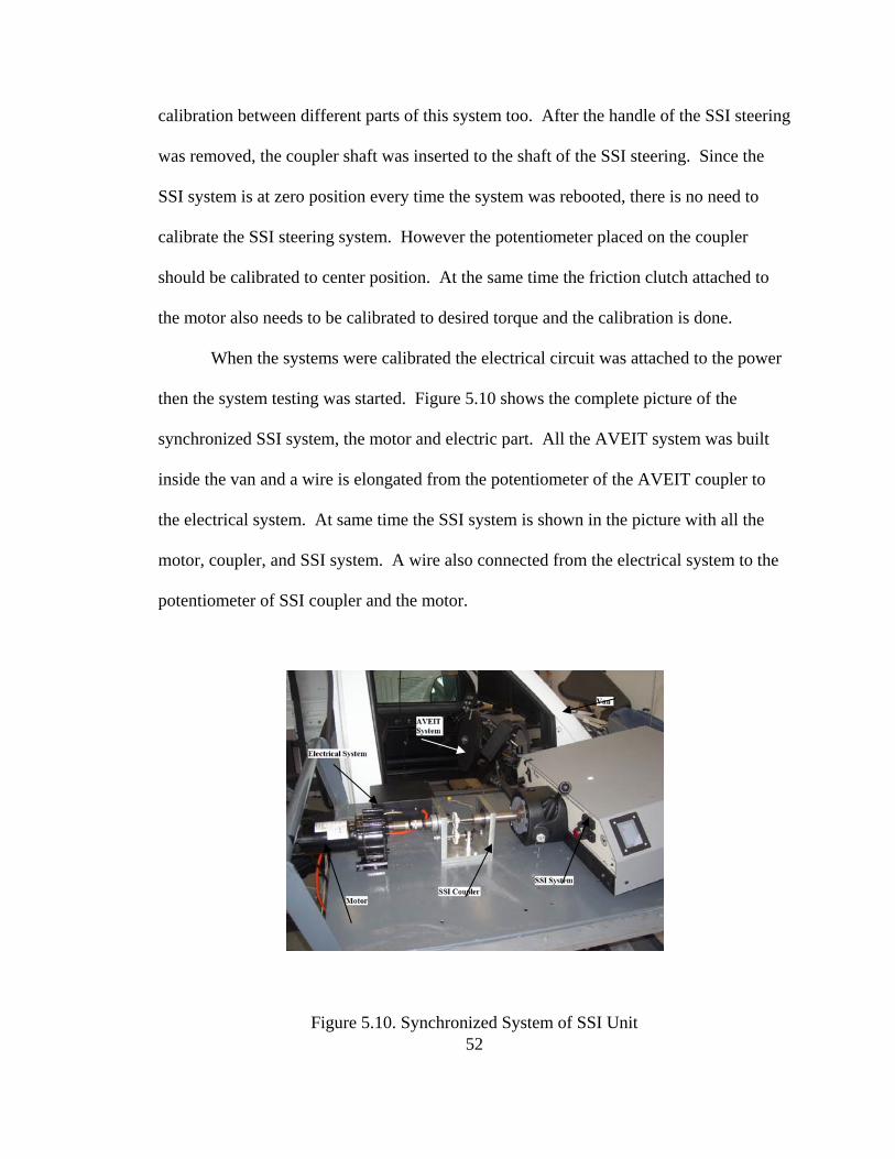
calibration between different parts of this system too. After the handle of the SSI steering
was removed, the coupler shaft was inserted to the shaft of the SSI steering. Since the
SSI system is at zero position every time the system was rebooted, there is no need to
calibrate the SSI steering system. However the potentiometer placed on the coupler
should be calibrated to center position. At the same time the friction clutch attached to
the motor also needs to be calibrated to desired torque and the calibration is done.
When the systems were calibrated the electrical circuit was attached to the power
then the system testing was started. Figure 5.10 shows the complete picture of the
synchronized SSI system, the motor and electric part. All the AVEIT system was built
inside the van and a wire is elongated from the potentiometer of the AVEIT coupler to
the electrical system. At same time the SSI system is shown in the picture with all the
motor, coupler, and SSI system. A wire also connected from the electrical system to the
potentiometer of SSI coupler and the motor.
52Figure 5.10. Synchronized System of SSI Unit
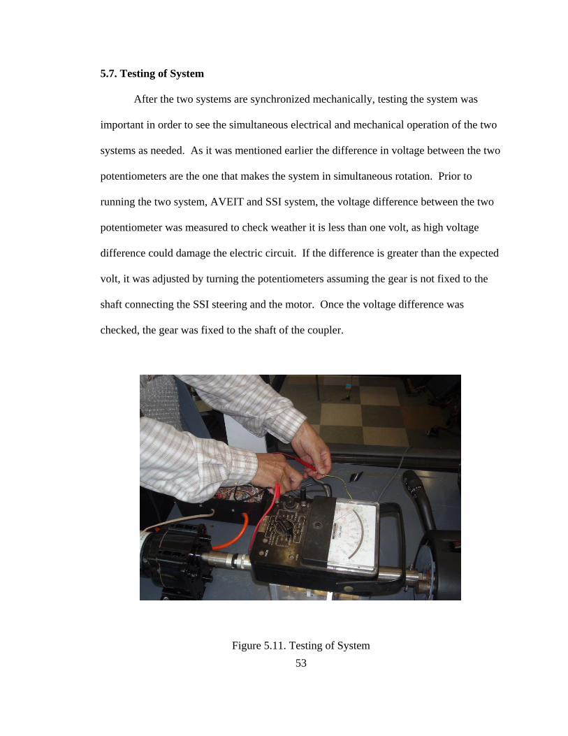
5.7. Testing of System
After the two systems are synchronized mechanically, testing the system was
important in order to see the simultaneous electrical and mechanical operation of the two
systems as needed. As it was mentioned earlier the difference in voltage between the two
potentiometers are the one that makes the system in simultaneous rotation. Prior to
running the two system, AVEIT and SSI system, the voltage difference between the two
potentiometer was measured to check weather it is less than one volt, as high voltage
difference could damage the electric circuit. If the difference is greater than the expected
volt, it was adjusted by turning the potentiometers assuming the gear is not fixed to the
shaft connecting the SSI steering and the motor. Once the voltage difference was
checked, the gear was fixed to the shaft of the coupler.
Figure 5.11. Testing of System 53
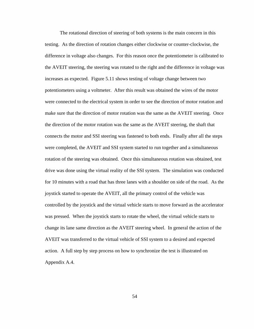
54
The rotational direction of steering of both systems is the main concern in this
testing. As the direction of rotation changes either clockwise or counter-clockwise, the
difference in voltage also changes. For this reason once the potentiometer is calibrated to
the AVEIT steering, the steering was rotated to the right and the difference in voltage was
increases as expected. Figure 5.11 shows testing of voltage change between two
potentiometers using a voltmeter. After this result was obtained the wires of the motor
were connected to the electrical system in order to see the direction of motor rotation and
make sure that the direction of motor rotation was the same as the AVEIT steering. Once
the direction of the motor rotation was the same as the AVEIT steering, the shaft that
connects the motor and SSI steering was fastened to both ends. Finally after all the steps
were completed, the AVEIT and SSI system started to run together and a simultaneous
rotation of the steering was obtained. Once this simultaneous rotation was obtained, test
drive was done using the virtual reality of the SSI system. The simulation was conducted
for 10 minutes with a road that has three lanes with a shoulder on side of the road. As the
joystick started to operate the AVEIT, all the primary control of the vehicle was
controlled by the joystick and the virtual vehicle starts to move forward as the accelerator
was pressed. When the joystick starts to rotate the wheel, the virtual vehicle starts to
change its lane same direction as the AVEIT steering wheel. In general the action of the
AVEIT was transferred to the virtual vehicle of SSI system to a desired and expected
action. A full step by step process on how to synchronize the test is illustrated on
Appendix A.4.
5.8. Block Diagram of the Mechanism
In order to provide a quick and good level view of the work and also to rapidly
lead to a point of interest, a block diagram will be of great help in giving a
comprehensive idea on how the mechanism work. For the mechanism the input will be
an AVEIT steering and the output is SSI load or SSI steering rotation.
Figure 5.12. Block Diagram of Mechanism
Figure 5.12 shows the block diagram of the mechanism. The potentiometer 2 and
the gear are located on the SSI coupler and the potentiometer 1 is located on the AVEIT
coupler. After the AVEIT system starts to run, there is an input signal from the
potentiometer 1 and at same time an output from potentiometer 2. The difference
between the input and output creates a potential difference or error signal and this error
signal, which is voltage difference, amplified at the electric circuit where its output
voltage applied to the motor. As the motor runs its torque applied to the SSI system. If
55
56
the AVEIT input was reversed by turning the opposite direction the system output also
reverse simultaneously and SSI system rotates same as AVEIT system.
5.9. Quantitative Result
After testing of the mechanism shows that the system is working properly, it is
necessary to support the practical outcome by a qualitative result. A test was done to
check the change in voltage between the two potentiometers using a digital oscilloscope.
The objective of this test is to confirm the behavior of the previous practical test based on
the specific key points. As it was mentioned before in the practical test, rotating the
AVEIT steering clockwise or counter-clockwise changes the sign of the voltage
difference, i.e. clockwise rotation of steering gives a positive voltage difference and
counter-clockwise rotation gives a negative voltage difference, between the two
potentiometers. As a result testing using quantitative method confirms the behaviors of
the system. In addition this method helps in finding the average value of voltage required
to rotate the motor by finding the voltage difference between the input and output voltage
applied to the potentiometers. Similarly finding the time delay between the two input and
output of the systems is of main objective of this test.
Before a qualitative test was started, a digital oscilloscope was used to gather the
data between the two potentiometer differences. The oscilloscope that been used for this
test was a PC based digital oscilloscope, DSO-8500, which is a product of Link
Instrument, Inc.
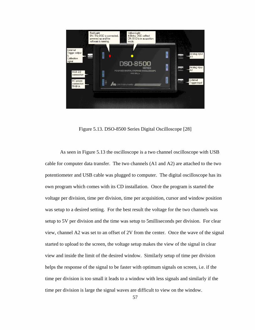
Figure 5.13. DSO-8500 Series Digital Oscilloscope [28]
As seen in Figure 5.13 the oscilloscope is a two channel oscilloscope with USB
cable for computer data transfer. The two channels (A1 and A2) are attached to the two
potentiometer and USB cable was plugged to computer. The digital oscilloscope has its
own program which comes with its CD installation. Once the program is started the
voltage per division, time per division, time per acquisition, cursor and window position
was setup to a desired setting. For the best result the voltage for the two channels was
setup to 5V per division and the time was setup to 5milliseconds per division. For clear
view, channel A2 was set to an offset of 2V from the center. Once the wave of the signal
started to upload to the screen, the voltage setup makes the view of the signal in clear
view and inside the limit of the desired window. Similarly setup of time per division
helps the response of the signal to be faster with optimum signals on screen, i.e. if the
time per division is too small it leads to a window with less signals and similarly if the
time per division is large the signal waves are difficult to view on the window. 57
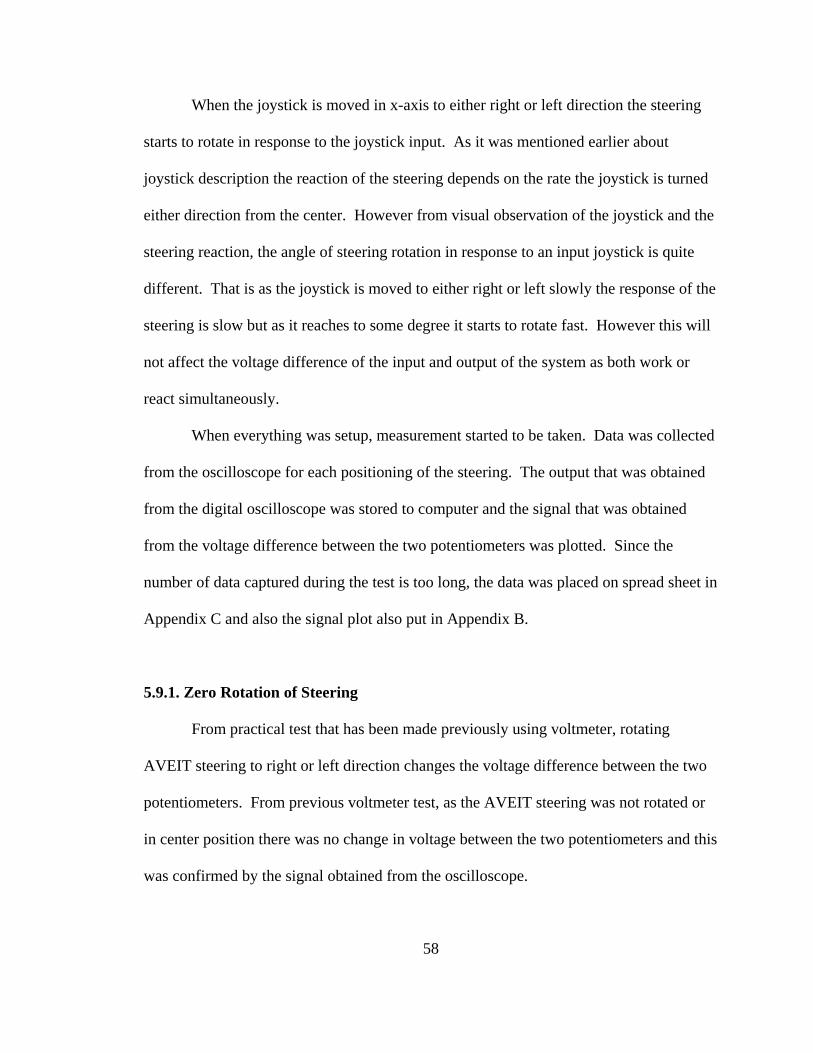
58
When the joystick is moved in x-axis to either right or left direction the steering
starts to rotate in response to the joystick input. As it was mentioned earlier about
joystick description the reaction of the steering depends on the rate the joystick is turned
either direction from the center. However from visual observation of the joystick and the
steering reaction, the angle of steering rotation in response to an input joystick is quite
different. That is as the joystick is moved to either right or left slowly the response of the
steering is slow but as it reaches to some degree it starts to rotate fast. However this will
not affect the voltage difference of the input and output of the system as both work or
react simultaneously.
When everything was setup, measurement started to be taken. Data was collected
from the oscilloscope for each positioning of the steering. The output that was obtained
from the digital oscilloscope was stored to computer and the signal that was obtained
from the voltage difference between the two potentiometers was plotted. Since the
number of data captured during the test is too long, the data was placed on spread sheet in
Appendix C and also the signal plot also put in Appendix B.
5.9.1. Zero Rotation of Steering
From practical test that has been made previously using voltmeter, rotating
AVEIT steering to right or left direction changes the voltage difference between the two
potentiometers. From previous voltmeter test, as the AVEIT steering was not rotated or
in center position there was no change in voltage between the two potentiometers and this
was confirmed by the signal obtained from the oscilloscope.
Figure 5.14. Signal of Center Position of Steering
Figure 5.14 shows a signal obtained when the steering was in center position. The
yellow line, F1, represents the change between the two channels. For the sake of clarity a
cursor was aligned to the peak of the three signals and kept at same place all the time
throughout the testing. As mentioned earlier channel A1 represents AVEIT
potentiometer and channel A2 represents SSI potentiometer. From this diagram it can be
understood that as the AVEIT steering is not rotated there is no change in voltage.
The figure is taken from the signal obtained during testing. It measures the
response of voltage change between two potentiometers. When there is no input rotation
from the steering or the steering is set at center position. As mentioned earlier time per
division of the program was set to 5 milliseconds and this result the collected data of the
59
60
reading to have a quite big files when the program runs for quite few minutes. For this
reason the first page of the figure is plotted on this section to represent the responses of
the two voltage difference. However, the detailed signal is shown in Appendix B.1.
5.9.2. Clockwise Rotation of Steering
When the steering of AVEIT is rotated toward right or clockwise direction, there
occur changes in voltage between the two potentiometers. This change in voltage
between the potentiometer makes the motor to rotate toward right. While the motor runs
its rotation also transferred to the other potentiometer which helps to control the change
in voltage between the potentiometers. The right rotation of the AVEIT steering makes a
positive change in voltage difference and this helps the motor to run in right direction.
Data collected on to the oscilloscope shows the two channels change its position from the
previous position by shifting upward. However the rate of change is not similar to both
channels which lead to a difference in voltage change between them. This difference in
voltage, F1, is represented by the yellow line which equals to the change in voltage
between the two potentiometers.
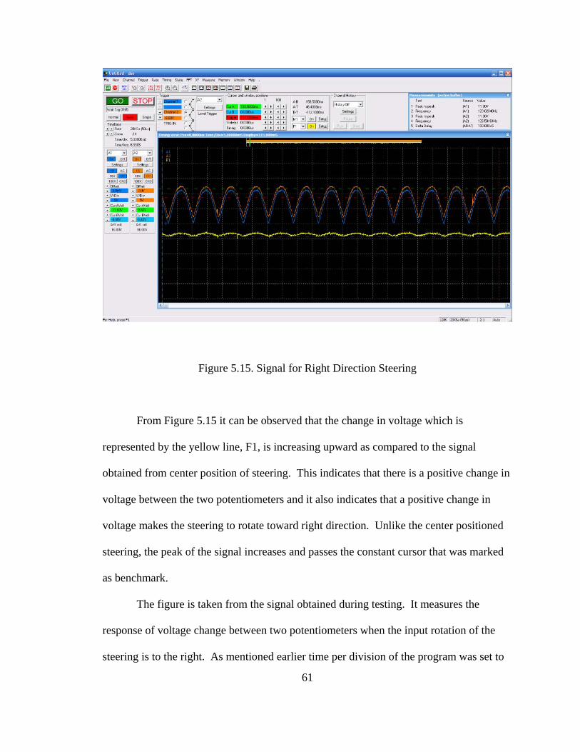
Figure 5.15. Signal for Right Direction Steering
From Figure 5.15 it can be observed that the change in voltage which is
represented by the yellow line, F1, is increasing upward as compared to the signal
obtained from center position of steering. This indicates that there is a positive change in
voltage between the two potentiometers and it also indicates that a positive change in
voltage makes the steering to rotate toward right direction. Unlike the center positioned
steering, the peak of the signal increases and passes the constant cursor that was marked
as benchmark.
The figure is taken from the signal obtained during testing. It measures the
response of voltage change between two potentiometers when the input rotation of the
steering is to the right. As mentioned earlier time per division of the program was set to
61
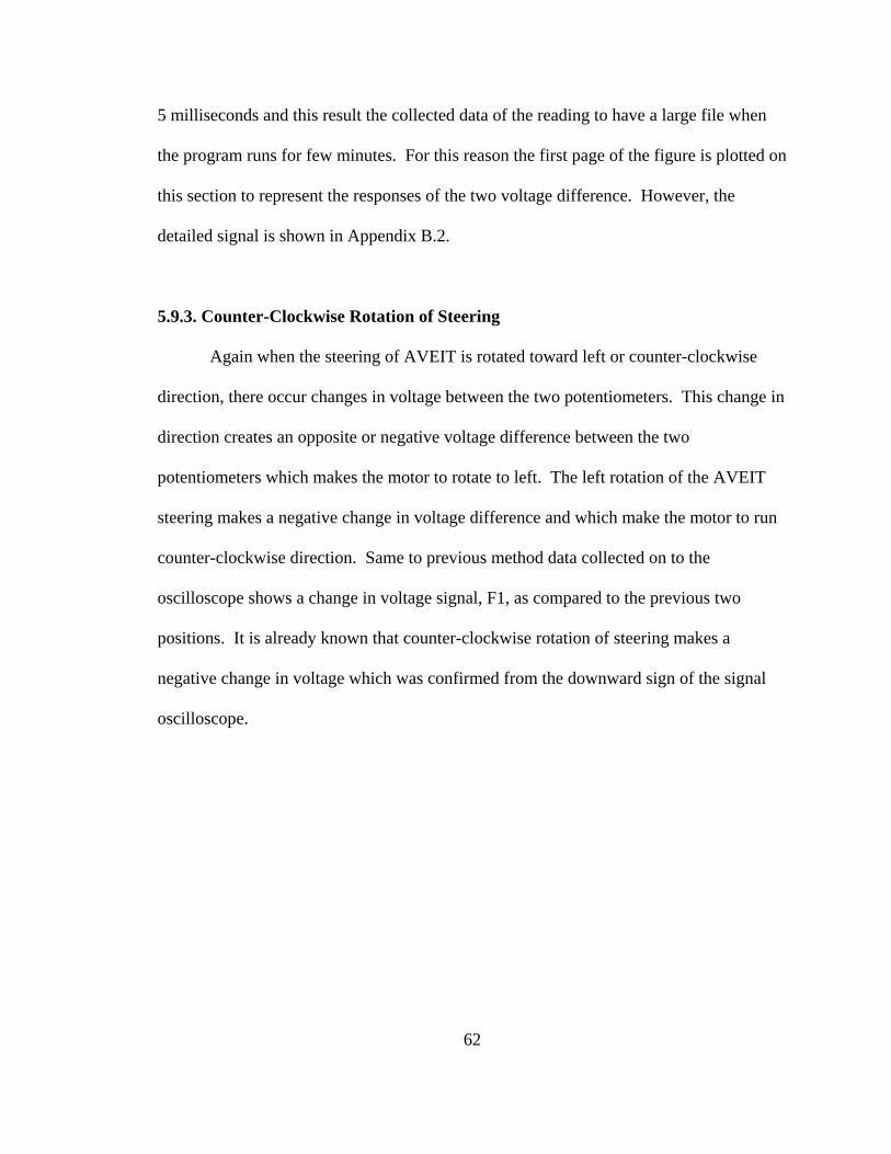
62
5 milliseconds and this result the collected data of the reading to have a large file when
the program runs for few minutes. For this reason the first page of the figure is plotted on
this section to represent the responses of the two voltage difference. However, the
detailed signal is shown in Appendix B.2.
5.9.3. Counter-Clockwise Rotation of Steering
Again when the steering of AVEIT is rotated toward left or counter-clockwise
direction, there occur changes in voltage between the two potentiometers. This change in
direction creates an opposite or negative voltage difference between the two
potentiometers which makes the motor to rotate to left. The left rotation of the AVEIT
steering makes a negative change in voltage difference and which make the motor to run
counter-clockwise direction. Same to previous method data collected on to the
oscilloscope shows a change in voltage signal, F1, as compared to the previous two
positions. It is already known that counter-clockwise rotation of steering makes a
negative change in voltage which was confirmed from the downward sign of the signal
oscilloscope.
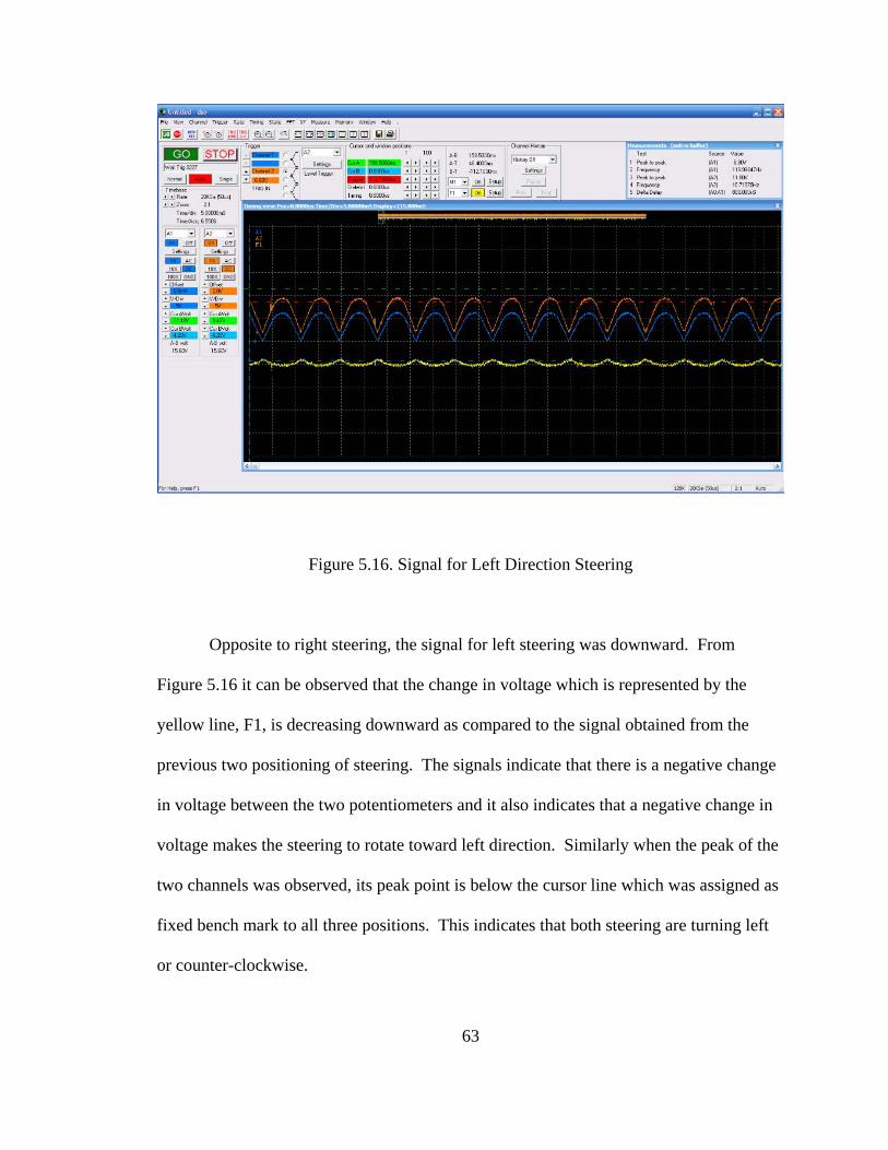
Figure 5.16. Signal for Left Direction Steering
Opposite to right steering, the signal for left steering was downward. From
Figure 5.16 it can be observed that the change in voltage which is represented by the
yellow line, F1, is decreasing downward as compared to the signal obtained from the
previous two positioning of steering. The signals indicate that there is a negative change
in voltage between the two potentiometers and it also indicates that a negative change in
voltage makes the steering to rotate toward left direction. Similarly when the peak of the
two channels was observed, its peak point is below the cursor line which was assigned as
fixed bench mark to all three positions. This indicates that both steering are turning left
or counter-clockwise.
63
64
The figure is taken from the signal obtained during testing. It measures the
response of voltage change between two potentiometers when the input rotation of the
steering is to the left. As mentioned earlier time per division of the program was set to 5
milliseconds and this result the collected data of the reading to have a large file when the
program runs for few minutes. For this reason the first page of the figure is plotted on
this section to represent the responses of the two voltage difference. The detailed signal
is shown in Appendix B.3.
5.10. Analysis of Testing
Once the mechanical and electrical designs were synchronized, a practical test
was conducted to check how the two systems act with each other. From the practical test,
using a voltmeter, it was found that with no input from the AVEIT potentiometer,
through AVEIT steering, there is zero voltage difference between the input and output
potentiometer of the systems. To confirm the practical test a qualitative test has been
made using the digital oscilloscope. As mentioned before, the potentiometers were
connected to the analog inputs (A1 and A2) of the digital oscilloscope and the data was
captured into the computer. After setting up the program to a desired setting, the
program was started to capture data and create a viewable signal on the oscilloscope
window of the computer. From the data stored and the signal captured there shows a
constant voltage reading and signal oscillation between the two potentiometers. The data
shows the two channels have an average voltage of 5.5V for each potentiometer and a
constant oscillation of the signal observed on the window. The difference in voltage, F1,
between the two channels shows a value of zero voltage difference. As it was mentioned
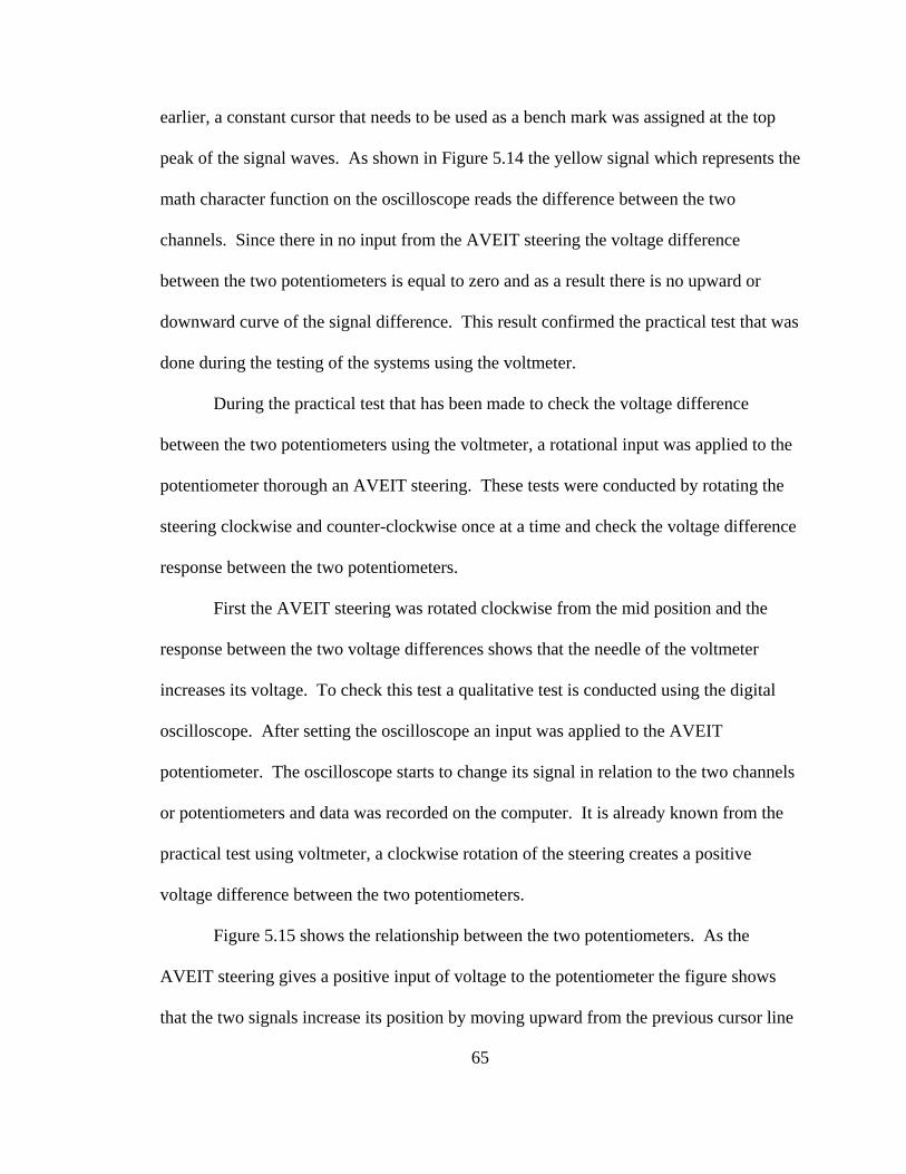
65
earlier, a constant cursor that needs to be used as a bench mark was assigned at the top
peak of the signal waves. As shown in Figure 5.14 the yellow signal which represents the
math character function on the oscilloscope reads the difference between the two
channels. Since there in no input from the AVEIT steering the voltage difference
between the two potentiometers is equal to zero and as a result there is no upward or
downward curve of the signal difference. This result confirmed the practical test that was
done during the testing of the systems using the voltmeter.
During the practical test that has been made to check the voltage difference
between the two potentiometers using the voltmeter, a rotational input was applied to the
potentiometer thorough an AVEIT steering. These tests were conducted by rotating the
steering clockwise and counter-clockwise once at a time and check the voltage difference
response between the two potentiometers.
First the AVEIT steering was rotated clockwise from the mid position and the
response between the two voltage differences shows that the needle of the voltmeter
increases its voltage. To check this test a qualitative test is conducted using the digital
oscilloscope. After setting the oscilloscope an input was applied to the AVEIT
potentiometer. The oscilloscope starts to change its signal in relation to the two channels
or potentiometers and data was recorded on the computer. It is already known from the
practical test using voltmeter, a clockwise rotation of the steering creates a positive
voltage difference between the two potentiometers.
Figure 5.15 shows the relationship between the two potentiometers. As the
AVEIT steering gives a positive input of voltage to the potentiometer the figure shows
that the two signals increase its position by moving upward from the previous cursor line
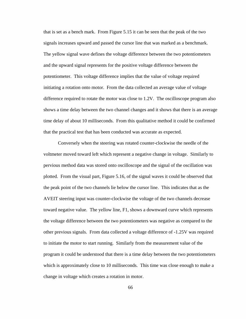
66
that is set as a bench mark. From Figure 5.15 it can be seen that the peak of the two
signals increases upward and passed the cursor line that was marked as a benchmark.
The yellow signal wave defines the voltage difference between the two potentiometers
and the upward signal represents for the positive voltage difference between the
potentiometer. This voltage difference implies that the value of voltage required
initiating a rotation onto motor. From the data collected an average value of voltage
difference required to rotate the motor was close to 1.2V. The oscilloscope program also
shows a time delay between the two channel changes and it shows that there is an average
time delay of about 10 milliseconds. From this qualitative method it could be confirmed
that the practical test that has been conducted was accurate as expected.
Conversely when the steering was rotated counter-clockwise the needle of the
voltmeter moved toward left which represent a negative change in voltage. Similarly to
pervious method data was stored onto oscilloscope and the signal of the oscillation was
plotted. From the visual part, Figure 5.16, of the signal waves it could be observed that
the peak point of the two channels lie below the cursor line. This indicates that as the
AVEIT steering input was counter-clockwise the voltage of the two channels decrease
toward negative value. The yellow line, F1, shows a downward curve which represents
the voltage difference between the two potentiometers was negative as compared to the
other previous signals. From data collected a voltage difference of -1.25V was required
to initiate the motor to start running. Similarly from the measurement value of the
program it could be understood that there is a time delay between the two potentiometers
which is approximately close to 10 milliseconds. This time was close enough to make a
change in voltage which creates a rotation in motor.
67
From the analysis it was understood that the two systems, AVEIT and SSI,
function simultaneously as expected. As there is an input rotation from the AVEIT
steering, the change in voltage that was created between the two potentiometers makes
the motor to run and simultaneously the output will transfer to SSI steering. This
practical test is supported by doing the qualitative test. From analyzing the test it is
confirmed that the change in input of AVEIT steering rotation to either clockwise or
counter-clockwise direction gives a simultaneous output of SSI steering rotation. This
test supports the thesis hypothesis by providing a qualitative result and showing how
effective the training method will be for persons with disability, i.e. as the there is an
input to steering from joystick the output obtained was consistent for both clockwise and
counter-clockwise direction. This test also helps the objectives of the thesis to meet its
goal by showing the accurate interface between the mechanical and electrical system and
also confirms the outcome of the practical test as expected which makes the system ready
for training.
68
Chapter 6
Conclusions and Recommendations
6.1. Conclusions
All AVEIT parts and SSI monitor were mounted inside the van as desired. The
longitudinal bar was strong enough to carry all the loads and the space was suitable for
operation during training. The AVEIT coupler was installed at the back of the AVEIT
steering system. When the joystick changes its direction, it shows a simultaneous
translation of rotation between the steering and the potentiometer.
The electrical system was put inside a commercialized box with wiring outlet so
that it would be easy to attache with the wiring of the battery and the potentiometers. In
addition to this, the motor, SSI coupler and SSI system was assembled together.
When all the design and assembly was finished the AVEIT driving aide and the
SSI unit are synchronized together electromechanically and have shown a smooth
transition of rotations between the two systems. This synchronization enables the
mechanical system of the AVEIT system to initiate the electrical system and change the
voltage outputs and from the electrical system it also converts to mechanical action of the
SSI system. Since the torque capacity of the SSI steering is about 10 in-lbf and the motor
has a torque capacity of 50 in-lbf, the friction clutch was adjusted closely to 10 in-lbf and
from the rotation test it could be observed the system will not face overload. The testing
69
of the system shows that a voltage difference of less than one volt is necessary to have
between the two potentiometers. Therefore prior to starting the mechanism again it is
necessary to check the voltage difference between the two potentiometers. After all this
procedure was taken into consideration the system was tested and both the AVEIT and
SSI system run successfully with a constant and smooth rotation.
The result for the practical part of the research was obtained as expected.
However it is important this practical test to be supported by quantitative result. For this
reason a digital oscilloscope was used to measure the action between the two systems by
checking its potentiometer difference. The voltage difference captured using the
oscilloscope confirmed that with a change in rotation there is a change in voltage between
the two potentiometer. The results show when the steering rotates in a clockwise
direction an upward voltage difference occurs and when the steering rotates oppositely, a
downward voltage difference occurs on the signal. Overall the objectives of the research
were met successfully.
This research helps in learning joystick operated driving aide by giving the real
feeling or feedback of the actual steering that is built on real vehicles as opposed to the
virtual joystick mounted on driving simulator. In addition to simultaneous rotation, the
use of electromechanical synchronization helps in its flexibility to a space constraint, i.e.
if there is no enough space between the two systems, AVEIT and SSI, integrating the two
systems electromechanically is of best advantage.
70
6.2. Final Recommendation
The primary control of the AVEIT driving system, i.e. steering and the gas/brake
servo, have been successfully interfaced and synchronized with the SSI system. When
the joystick started to activate on steering servo, the joystick does not have high
sensitivity. This necessitates an application of some extra force on the joystick for the
steering to rotate, however once the joystick turns approximately 10 degree, the rotation
of the steering wheel speeds up faster. This becomes a minor problem which needs an
extra care and practice when operating the joystick. To improve the electro-mechanical
synchronization of the two systems it is recommended to use a joystick with high
sensitivity. When the system starts to run, the electric circuit get overheat after the motor
runs for over 30 minutes. It is recommended to modify the resistors so that it could
withstand extra current. During operation the motor have loud noise which is not
comfortable to operate close to the system. For the benefit of the operator it is
recommended to improve the sound of the motor by either changing the motor or build a
sound proof cover. The power supply that was used during this research was AC power
supply. It is recommended to conduct a DC power supply and compare the result of the
two powers. In order to check the robustness of the system it is recommended to conduct
a multiple trials. As future work it is recommended to conduct testing on persons with
disability and make conclusion based on the outcome of the result. As an additional
recommendation, an evolution of AVEIT system with its driving simulator in one unit
will be of great benefit for training persons with disability.
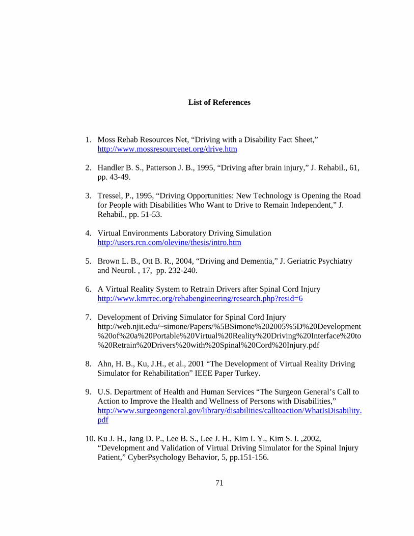
71
List of References
1. Moss Rehab Resources Net, “Driving with a Disability Fact Sheet,” http://www.mossresourcenet.org/drive.htm
2. Handler B. S., Patterson J. B., 1995, “Driving after brain injury,” J. Rehabil., 61,
pp. 43-49.
3. Tressel, P., 1995, “Driving Opportunities: New Technology is Opening the Road for People with Disabilities Who Want to Drive to Remain Independent,” J. Rehabil., pp. 51-53.
4. Virtual Environments Laboratory Driving Simulation
http://users.rcn.com/olevine/thesis/intro.htm
5. Brown L. B., Ott B. R., 2004, “Driving and Dementia,” J. Geriatric Psychiatry and Neurol. , 17, pp. 232-240.
6. A Virtual Reality System to Retrain Drivers after Spinal Cord Injury
http://www.kmrrec.org/rehabengineering/research.php?resid=6 7. Development of Driving Simulator for Spinal Cord Injury
http://web.njit.edu/~simone/Papers/%5BSimone%202005%5D%20Development%20of%20a%20Portable%20Virtual%20Reality%20Driving%20Interface%20to%20Retrain%20Drivers%20with%20Spinal%20Cord%20Injury.pdf
8. Ahn, H. B., Ku, J.H., et al., 2001 “The Development of Virtual Reality Driving
Simulator for Rehabilitation” IEEE Paper Turkey. 9. U.S. Department of Health and Human Services “The Surgeon General’s Call to
Action to Improve the Health and Wellness of Persons with Disabilities,” http://www.surgeongeneral.gov/library/disabilities/calltoaction/WhatIsDisability.pdf
10. Ku J. H., Jang D. P., Lee B. S., Lee J. H., Kim I. Y., Kim S. I. ,2002,
“Development and Validation of Virtual Driving Simulator for the Spinal Injury Patient,” CyberPsychology Behavior, 5, pp.151-156.
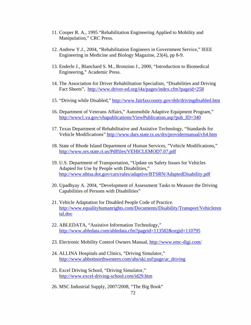
72
11. Cooper R. A., 1995 “Rehabilitation Engineering Applied to Mobility and Manipulation,” CRC Press.
12. Andrew Y.J., 2004, “Rehabilitation Engineers in Government Service,” IEEE
Engineering in Medicine and Biology Magazine, 23(4), pp 8-9.
13. Enderle J., Blanchard S. M., Bronzino J., 2000, “Introduction to Biomedical Engineering,” Academic Press.
14. The Association for Driver Rehabilitation Specialists, “Disabilities and Driving
Fact Sheets”, http://www.driver-ed.org/i4a/pages/index.cfm?pageid=258
15. “Driving while Disabled,” http://www.fairfaxcounty.gov/dsb/drivingdisabled.htm
16. Department of Veterans Affairs,” Automobile Adaptive Equipment Program,” http://www1.va.gov/vhapublications/ViewPublication.asp?pub_ID=340
17. Texas Department of Rehabilitative and Assistive Technology, “Standards for
Vehicle Modifications” http://www.dars.state.tx.us/drs/providermanual/ch4.htm 18. State of Rhode Island Department of Human Services, ”Vehicle Modifications,”
http://www.ors.state.ri.us/Pdffiles/VEHICLEMOD7.07.pdf 19. U.S. Department of Transportation, “Update on Safety Issues for Vehicles
Adapted for Use by People with Disabilities,” http://www.nhtsa.dot.gov/cars/rules/adaptive/BTSRN/AdaptedDisability.pdf
20. Upadhyay A. 2004, “Development of Assessment Tasks to Measure the Driving
Capabilities of Persons with Disabilities” 21. Vehicle Adaptation for Disabled People Code of Practice.
http://www.equalityhumanrights.com/Documents/Disability/Transport/Vehiclerental.doc
22. ABLEDATA, “Assistive Information Technology,”
http://www.abledata.com/abledata.cfm?pageid=113582&orgid=110795
23. Electronic Mobility Control Owners Manual, http://www.emc-digi.com/
24. ALLINA Hospitals and Clinics, “Driving Simulator,” http://www.abbottnorthwestern.com/ahs/ski.nsf/page/ar_driving
25. Excel Driving School, “Driving Simulator,”
http://www.excel-driving-school.com/id29.htm
26. MSC Industrial Supply, 2007/2008, “The Big Book”

73
27. Operation manual S-3100/S-3300 Series http://www.simulatorsystems.com/Auto/handcontrolp1.htm
28. Link Instruments, Inc. 2006, “DSO Software Manual”

74
Appendices
75
Appendix A: Step-Wise Procedures
A.1. Procedure for Booting the AEVIT Driving System
• Make sure the battery is fully charged, if not charge the battery using the charger
accompanied with the system.
• Check all the connections for the system; the steering device and the gas/brake
device should be connected to their respective drive modules.
• Now connect the two probes of the vehicle simulator to the battery, be careful
regarding the polarity to prevent any short circuit.
• After connecting the vehicle simulator put the three switches ON (simulator
power, ignition and engaged buttons). This makes the system ready for booting.
• At this point the information center display is on. Now rotate the steering input
device in clockwise and counter-clockwise direction until the message on the
display shows steering device OK. Next push the gas and brake lever forward
and backward until the message shows gas/brake device OK.
• After both the devices show ok on the message the system is booted and ready for
further operation.
• To put the system off, switch off the same three switches and also the remote
switch. This will shut the system completely.
A.2. Procedure for Booting the SSI Computer
• After all the components have been properly placed and connected the system is
ready to turn the power on and start the simulator.
76
Appendix A (Continued)
• On the back panel of the control consol flip the switch from “O” to the “I”
position. At this time nothing happens to the system.
• Push and hold for one second the reset/power on switch located at the back of the
consol to turn on the control consol.
• Turn the power on to the video monitor.
• At this point the main computer is booting up and various video images being
displayed on the monitor. If this video image does not come up, it is necessary to
check the monitor connections and make sure power is on.
• Once the simulator software has finished loading a touch pad screen image will be
displayed on the monitor.
• Either using the built in Touch Pad or USB mouse click on the screen and this
leads to the Log in Screen.
• As user name and password were entered the system will allow the user to take to
the simulation by clicking on GO TO THE SIMULATION button.
• The main menu will then appear and chose one level from the 5 available main
areas.
• Then the system will show different areas of driving and also helps the user to get
acquainted with the system [27].
A.3. Procedure for Calibrating the AVEIT and SSI Systems
• Make sure all the power connection to the electrical circuit is dismantled.
• Loosen the connection between the potentiometer and the AVEIT steering.
77
Appendix A (Continued)
• Boot the AVEIT steering according to the appendix A.1.
• Once the AVEIT is calibrated to zero position start to calibrate the potentiometer
to center position by turning five turns from the end position.
• After the potentiometer positioned at center, fasten the screw that attaches the
steering shaft and the shaft of the coupler.
• Boot the SSI system according to the appendix A.2.
• The steering of the SSI system is at center position and does not need calibration.
• Loosen the screws that tight the two gears in the SSI coupler.
• Calibrate the SSI potentiometer by turning five turns from the end to make it at
the center position.
• Then tighten the screws of the gears attached to the shaft.
• Once all are calibrated connect the electric wiring to the power.
A.4. Procedure for the Use of the Synchronized Circuit
• Check the voltage between the two potentiometers. The center wire connected to
#3 of AD706 is to be connected with the potentiometer for AVEIT system. The
voltage should be less than one volt. Assume that the shafts of the potentiometers
are not fixed to the steering shaft. The shaft of the potentiometer can be moved by
fingers.
• Fix the shafts of potentiometers to the steering shafts. Rotate the shaft of the
potentiometer connected to AVEIT system and check the voltage difference. The
right direction is for increasing of the voltage difference. Keep the cover on the
78
Appendix A (Continued)
synchronized circuit and watch the solenoids, see they are on and off as expected,
as the potentiometer turned to two different directions.
• If the above operation is normal, connect the wires to the motor. Plug in the
power to the synchronized circuit very briefly to see the motor is rotating in the
same direction as AVEIT steering system.
• If every thing is normal, plug in the power 115 VAC, rotate AVEIT steering with
a small angle and stop. Watch carefully what the response of the SSI steering.
The SSI steering is expected to rotate back and forth in the small angle of rotation.
• If everything is normal then watch it to operate by itself for a while and then
practice to drive the AVEIT system.
• Before stop the two systems make certain the two steering wheels are in the
middle positions. Unplug the power and turn off the powers for the two systems.
Do not move the steering wheels on both systems.
• Before start the systems again, turn on the AVEIT system, boot the system, and
keep the steering wheel in the middle. Turn on the SSI system and keep the
steering wheel in the middle position. Plug in the power 115 VAC for the
synchronized circuit. Start the operation of the AVEIT system. And watch the
response of the SSI system.
79
Appendix B: Oscilloscope Captured Signals
B.1. Mid Steering Position
This is a plot captured from the digital PC oscilloscope for mid steering position.
The plot represents a voltage signal of two channels (A1 and A2) representing the input
and output potentiometer. A1 represents input potentiometer for AVEIT steering and A2
represents output potentiometer for SSI steering. The difference between the A1 and A2
is representing by F1. As you see on the plot A1 has blue line color, A2 has orange line
color and F1 has yellow line color. Based on system test preference the voltage per
division was set to 5V and time per division was set to 5 milliseconds per division. For
the sake of clear view, the two channels are offset differently. Offset for channel A1 is
zero while A2 is offset by 2V; hence this offset helps the view of the two channels as
clear as possible. From the plot it is easy to see A2 above A1; however this difference in
offset does not influence the voltage value of the channels. The plot has a cursor line
crossing horizontally with a different color line of green, red and cyan. These cursor
lines were set as a bench mark for all three steering rotation and become fixed at same
position for the entire test. This will help to examine how the peak point of the voltage
signal changes with changing the rotation. From the test it can be observed that when the
steering is not rotating or the position of the steering is at mid position, there is no change
in voltage between the two channels A1 and A2. The cursor line touches the peak point
of each channel A1 and A2 and the difference in voltage of F1. Since there is no
difference in voltage between the two channels, the yellow line, F1, has a straight line
which means zero difference in voltage between the two potentiometers. The zero value

80
Appendix B (Continued)
of the voltage difference between the two systems shows that the two systems are
synchronized successfully, i.e. when the difference between the two voltages in the
steering system are the same it tells that the system are synchronized successfully.
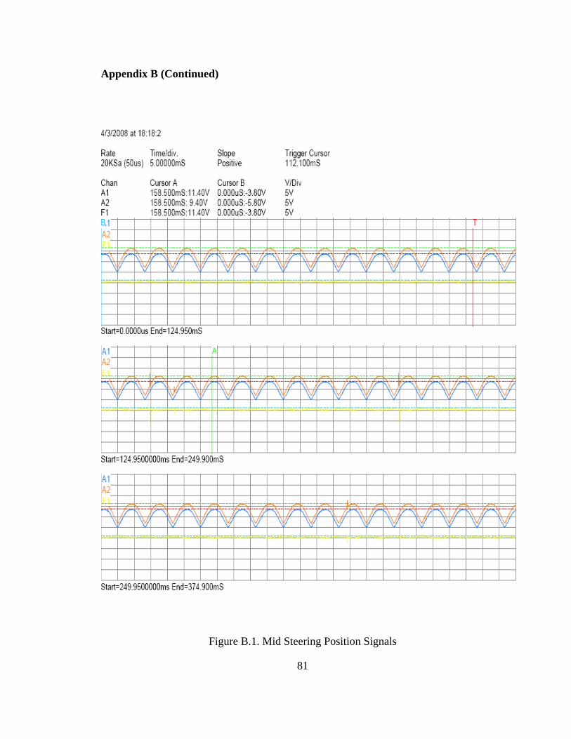
Appendix B (Continued)
Figure B.1. Mid Steering Position Signals
81
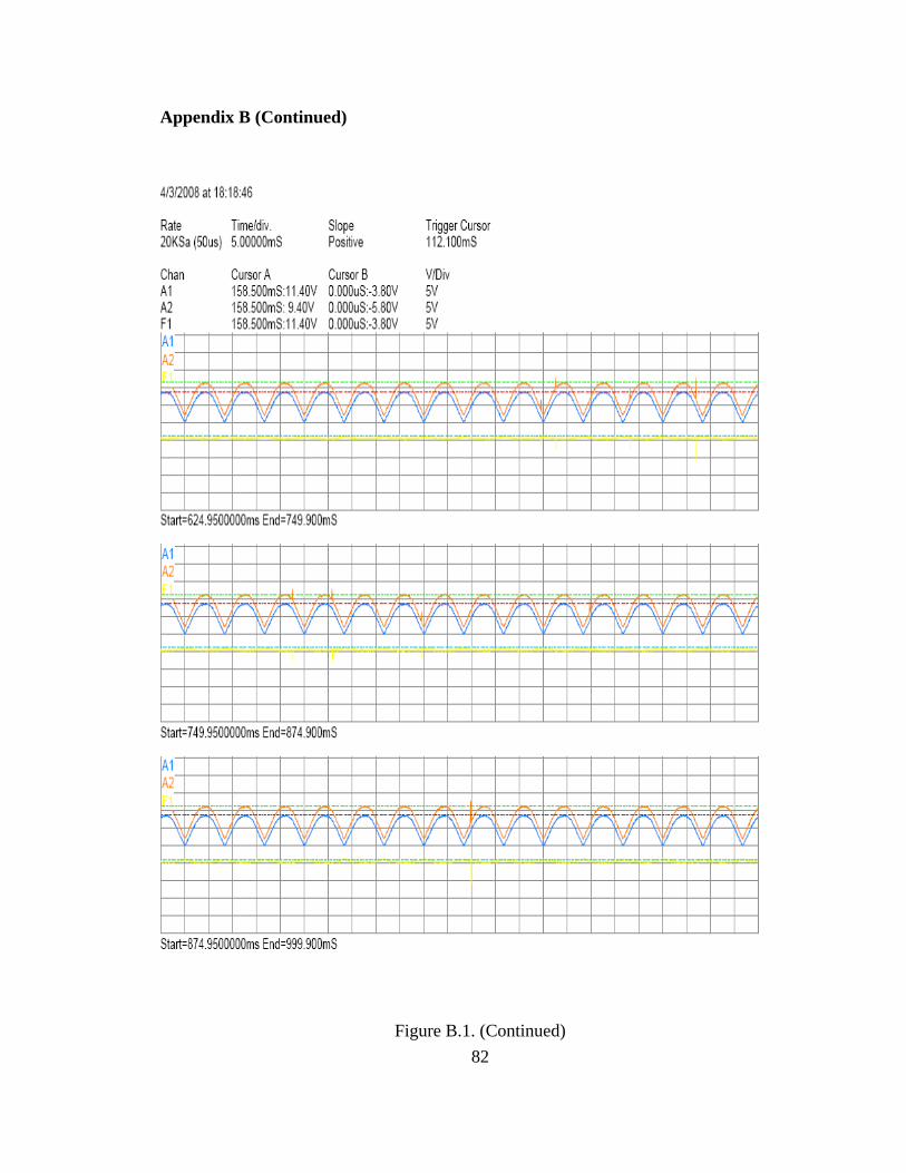
Appendix B (Continued)
Figure B.1. (Continued) 82
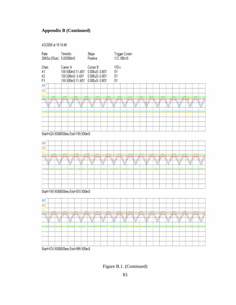
Appendix B (Continued)
Figure B.1. (Continued)
83
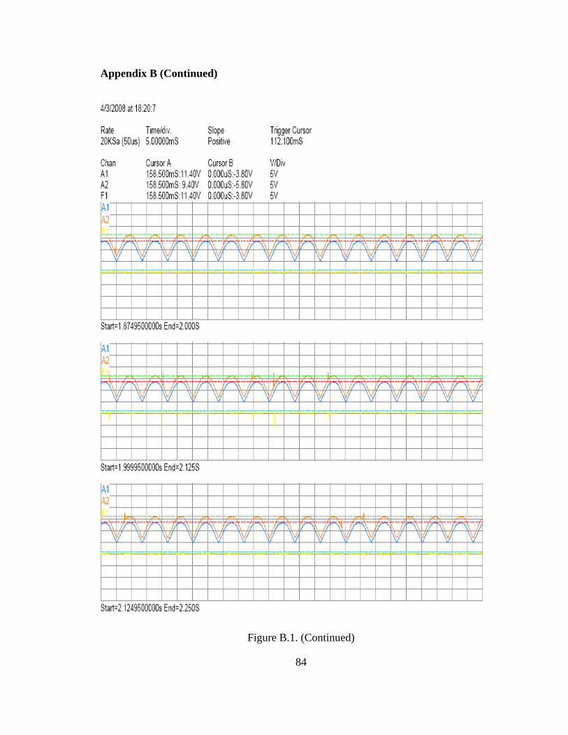
Appendix B (Continued)
Figure B.1. (Continued)
84
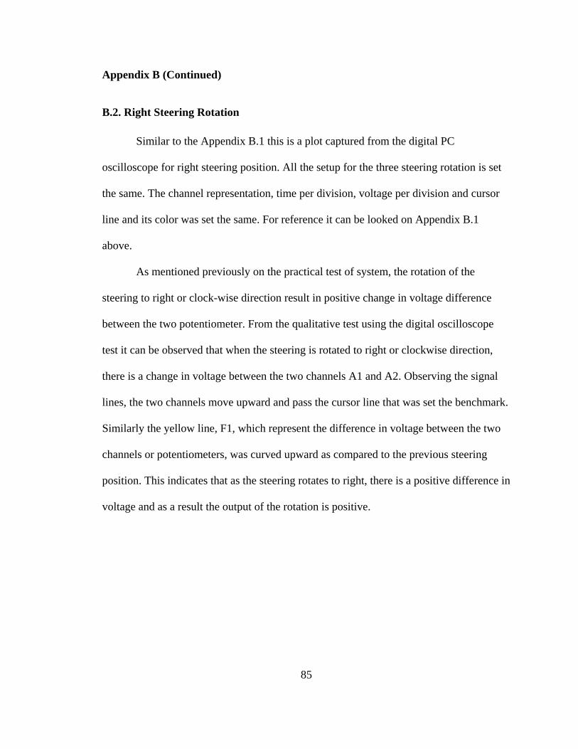
85
Appendix B (Continued)
B.2. Right Steering Rotation
Similar to the Appendix B.1 this is a plot captured from the digital PC
oscilloscope for right steering position. All the setup for the three steering rotation is set
the same. The channel representation, time per division, voltage per division and cursor
line and its color was set the same. For reference it can be looked on Appendix B.1
above.
As mentioned previously on the practical test of system, the rotation of the
steering to right or clock-wise direction result in positive change in voltage difference
between the two potentiometer. From the qualitative test using the digital oscilloscope
test it can be observed that when the steering is rotated to right or clockwise direction,
there is a change in voltage between the two channels A1 and A2. Observing the signal
lines, the two channels move upward and pass the cursor line that was set the benchmark.
Similarly the yellow line, F1, which represent the difference in voltage between the two
channels or potentiometers, was curved upward as compared to the previous steering
position. This indicates that as the steering rotates to right, there is a positive difference in
voltage and as a result the output of the rotation is positive.
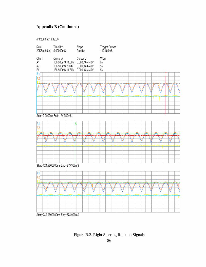
Appendix B (Continued)
Figure B.2. Right Steering Rotation Signals 86
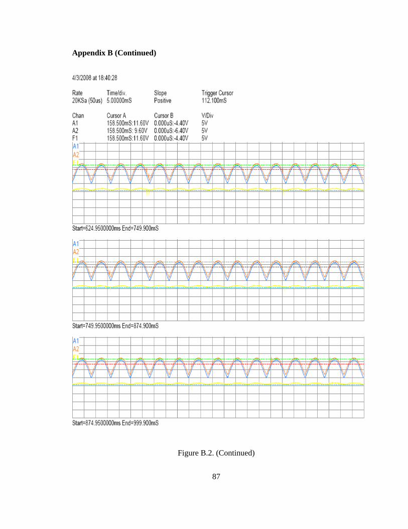
Appendix B (Continued)
Figure B.2. (Continued)
87
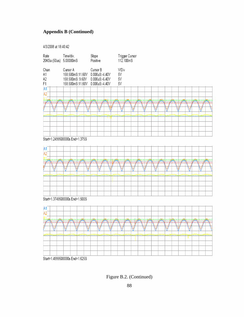
Appendix B (Continued)
Figure B.2. (Continued)
88
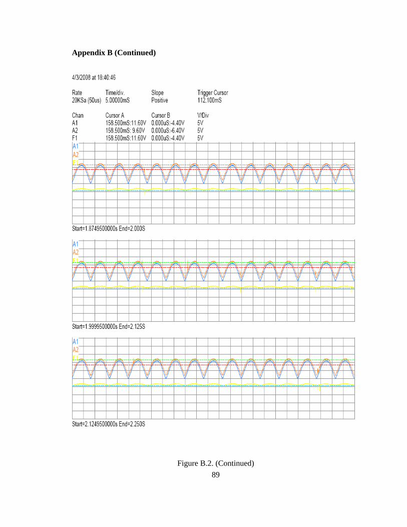
Appendix B (Continued)
Figure B.2. (Continued) 89
90
Appendix B (Continued)
B.3. Left Steering Rotation
This is a plot captured from the digital PC oscilloscope for left steering position.
All the setup for the three steering rotation is set the same. The channel representation,
time per division, voltage per division and cursor line and its color was set the same. For
reference it can be looked on Appendix B.1 above.
As mentioned previously on the practical test of the system, the rotation of the
steering to left or counter clock-wise direction result in negative change in voltage
difference between the two potentiometers. From the qualitative test using the digital
oscilloscope test it can be observed that when the steering is rotated to left or counter-
clockwise direction, there is a change in voltage between the two channels A1 and A2.
Observing the signal lines, the two channels move downward below the cursor line.
Similarly the yellow line, F1, which represent the difference in voltage between the two
channels or potentiometers, was curved downward as compared to the previous steering
positions. This indicates that as the steering rotates to left, there is a negative difference
in voltage and as a result the output of the rotation is negative.
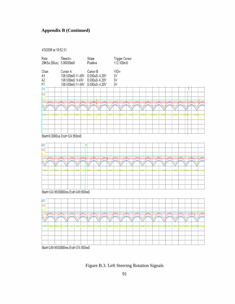
Appendix B (Continued)
Figure B.3. Left Steering Rotation Signals
91
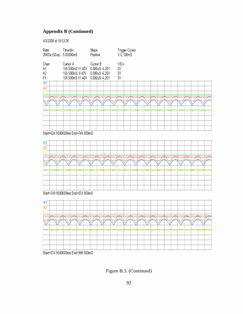
Appendix B (Continued)
Figure B.3. (Continued)
92
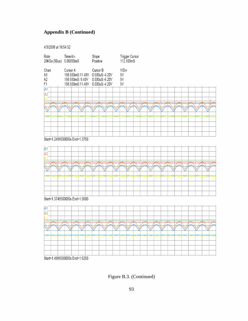
Appendix B (Continued)
Figure B.3. (Continued)
93
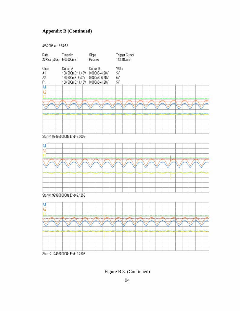
Appendix B (Continued)
Figure B.3. (Continued)
94
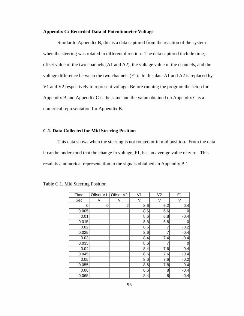
95
Appendix C: Recorded Data of Potentiometer Voltage
Similar to Appendix B, this is a data captured from the reaction of the system
when the steering was rotated in different direction. The data captured include time,
offset value of the two channels (A1 and A2), the voltage value of the channels, and the
voltage difference between the two channels (F1). In this data A1 and A2 is replaced by
V1 and V2 respectively to represent voltage. Before running the program the setup for
Appendix B and Appendix C is the same and the value obtained on Appendix C is a
numerical representation for Appendix B.
C.1. Data Collected for Mid Steering Position
This data shows when the steering is not rotated or in mid position. From the data
it can be understood that the change in voltage, F1, has an average value of zero. This
result is a numerical representation to the signals obtained an Appendix B.1.
Table C.1. Mid Steering Position
Time Offset V1 Offset V2 V1 V2 F1 Sec V V V V V
0 0 2 8.6 6.2 0.4 0.005 8.6 6.6 0
0.01 8.6 6.8 -0.4 0.015 8.6 6.8 0
0.02 8.6 7 -0.2 0.025 8.6 7 -0.4
0.03 8.4 7.4 -0.4 0.035 8.6 7 0
0.04 8.4 7.6 -0.4 0.045 8.6 7.6 -0.4
0.05 8.6 7.6 -0.2 0.055 8.6 7.8 -0.4
0.06 8.6 8 -0.4 0.065 8.4 8 -0.4
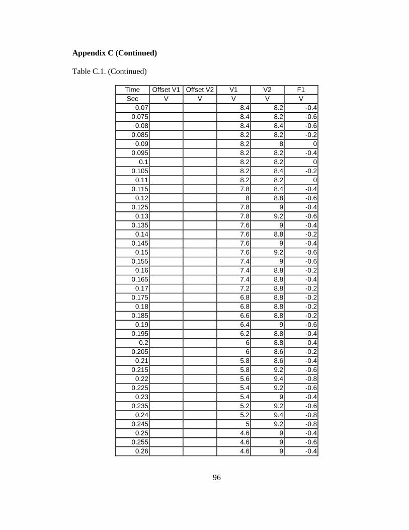
96
Appendix C (Continued)
Table C.1. (Continued)
Time Offset V1 Offset V2 V1 V2 F1 Sec V V V V V
0.07 8.4 8.2 -0.4 0.075 8.4 8.2 -0.6
0.08 8.4 8.4 -0.6 0.085 8.2 8.2 -0.2
0.09 8.2 8 0 0.095 8.2 8.2 -0.4
0.1 8.2 8.2 0 0.105 8.2 8.4 -0.2
0.11 8.2 8.2 0 0.115 7.8 8.4 -0.4
0.12 8 8.8 -0.6 0.125 7.8 9 -0.4
0.13 7.8 9.2 -0.6 0.135 7.6 9 -0.4
0.14 7.6 8.8 -0.2 0.145 7.6 9 -0.4
0.15 7.6 9.2 -0.6 0.155 7.4 9 -0.6
0.16 7.4 8.8 -0.2 0.165 7.4 8.8 -0.4
0.17 7.2 8.8 -0.2 0.175 6.8 8.8 -0.2
0.18 6.8 8.8 -0.2 0.185 6.6 8.8 -0.2
0.19 6.4 9 -0.6 0.195 6.2 8.8 -0.4
0.2 6 8.8 -0.4 0.205 6 8.6 -0.2
0.21 5.8 8.6 -0.4 0.215 5.8 9.2 -0.6
0.22 5.6 9.4 -0.8 0.225 5.4 9.2 -0.6
0.23 5.4 9 -0.4 0.235 5.2 9.2 -0.6
0.24 5.2 9.4 -0.8 0.245 5 9.2 -0.8
0.25 4.6 9 -0.4 0.255 4.6 9 -0.6
0.26 4.6 9 -0.4
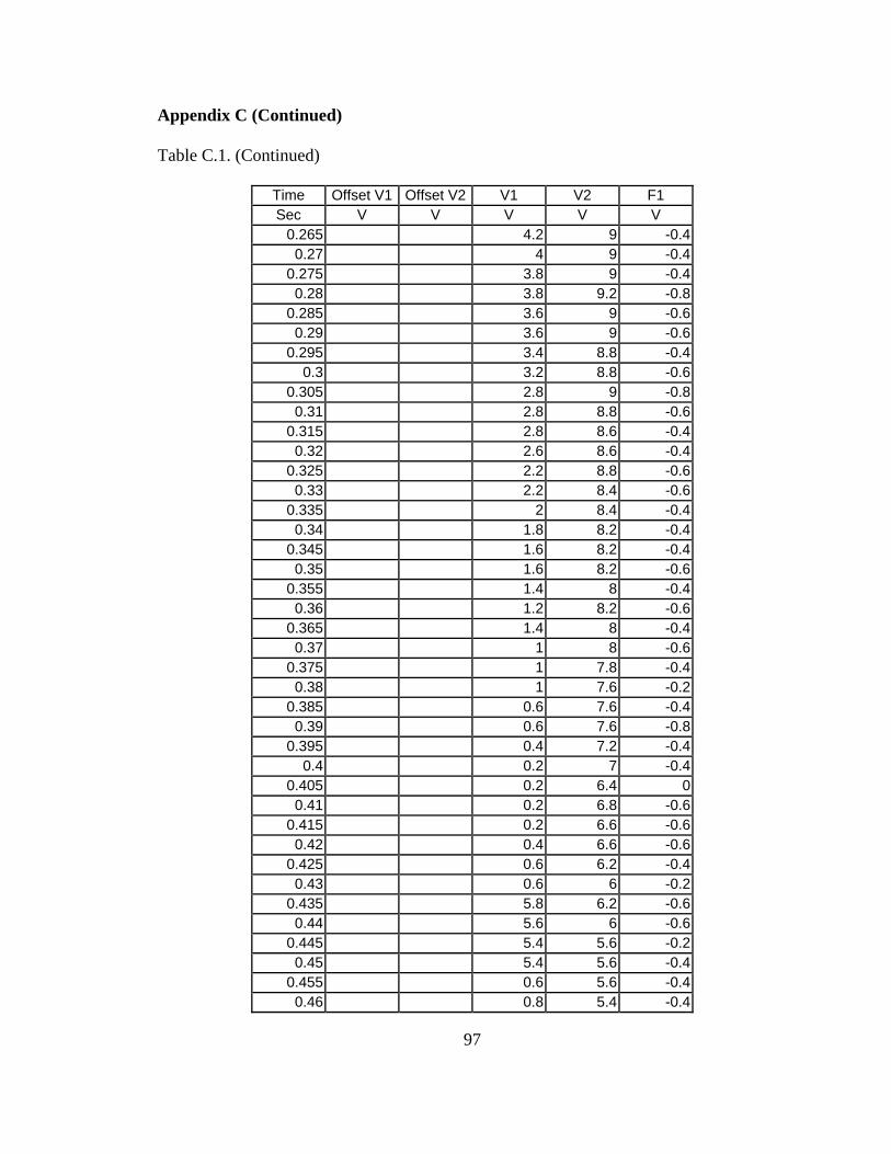
97
Appendix C (Continued)
Table C.1. (Continued)
Time Offset V1 Offset V2 V1 V2 F1 Sec V V V V V
0.265 4.2 9 -0.4 0.27 4 9 -0.4
0.275 3.8 9 -0.4 0.28 3.8 9.2 -0.8
0.285 3.6 9 -0.6 0.29 3.6 9 -0.6
0.295 3.4 8.8 -0.4 0.3 3.2 8.8 -0.6
0.305 2.8 9 -0.8 0.31 2.8 8.8 -0.6
0.315 2.8 8.6 -0.4 0.32 2.6 8.6 -0.4
0.325 2.2 8.8 -0.6 0.33 2.2 8.4 -0.6
0.335 2 8.4 -0.4 0.34 1.8 8.2 -0.4
0.345 1.6 8.2 -0.4 0.35 1.6 8.2 -0.6
0.355 1.4 8 -0.4 0.36 1.2 8.2 -0.6
0.365 1.4 8 -0.4 0.37 1 8 -0.6
0.375 1 7.8 -0.4 0.38 1 7.6 -0.2
0.385 0.6 7.6 -0.4 0.39 0.6 7.6 -0.8
0.395 0.4 7.2 -0.4 0.4 0.2 7 -0.4
0.405 0.2 6.4 0 0.41 0.2 6.8 -0.6
0.415 0.2 6.6 -0.6 0.42 0.4 6.6 -0.6
0.425 0.6 6.2 -0.4 0.43 0.6 6 -0.2
0.435 5.8 6.2 -0.6 0.44 5.6 6 -0.6
0.445 5.4 5.6 -0.2 0.45 5.4 5.6 -0.4
0.455 0.6 5.6 -0.4 0.46 0.8 5.4 -0.4
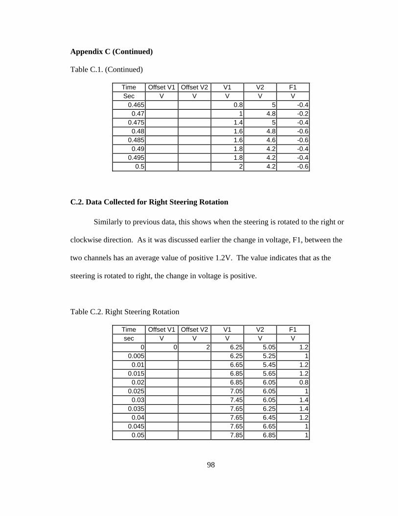
98
Appendix C (Continued)
Table C.1. (Continued)
Time Offset V1 Offset V2 V1 V2 F1 Sec V V V V V
0.465 0.8 5 -0.4 0.47 1 4.8 -0.2
0.475 1.4 5 -0.4 0.48 1.6 4.8 -0.6
0.485 1.6 4.6 -0.6 0.49 1.8 4.2 -0.4
0.495 1.8 4.2 -0.4 0.5 2 4.2 -0.6
C.2. Data Collected for Right Steering Rotation
Similarly to previous data, this shows when the steering is rotated to the right or
clockwise direction. As it was discussed earlier the change in voltage, F1, between the
two channels has an average value of positive 1.2V. The value indicates that as the
steering is rotated to right, the change in voltage is positive.
Table C.2. Right Steering Rotation
Time Offset V1 Offset V2 V1 V2 F1 sec V V V V V
0 0 2 6.25 5.05 1.2 0.005 6.25 5.25 1
0.01 6.65 5.45 1.2 0.015 6.85 5.65 1.2
0.02 6.85 6.05 0.8 0.025 7.05 6.05 1
0.03 7.45 6.05 1.4 0.035 7.65 6.25 1.4
0.04 7.65 6.45 1.2 0.045 7.65 6.65 1
0.05 7.85 6.85 1
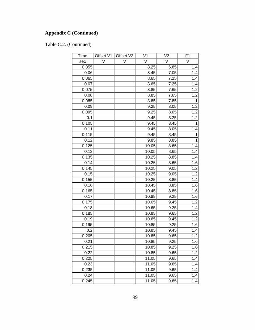
99
Appendix C (Continued)
Table C.2. (Continued)
Time Offset V1 Offset V2 V1 V2 F1 sec V V V V V
0.055 8.25 6.85 1.4 0.06 8.45 7.05 1.4
0.065 8.65 7.25 1.4 0.07 8.65 7.25 1.4
0.075 8.85 7.65 1.2 0.08 8.85 7.65 1.2
0.085 8.85 7.85 1 0.09 9.25 8.05 1.2
0.095 9.25 8.05 1.2 0.1 9.45 8.25 1.2
0.105 9.45 8.45 1 0.11 9.45 8.05 1.4
0.115 9.45 8.45 1 0.12 9.85 8.85 1
0.125 10.05 8.65 1.4 0.13 10.05 8.65 1.4
0.135 10.25 8.85 1.4 0.14 10.25 8.65 1.6
0.145 10.25 9.05 1.2 0.15 10.25 9.05 1.2
0.155 10.25 8.85 1.4 0.16 10.45 8.85 1.6
0.165 10.45 8.85 1.6 0.17 10.85 9.25 1.6
0.175 10.65 9.45 1.2 0.18 10.65 9.25 1.4
0.185 10.85 9.65 1.2 0.19 10.65 9.45 1.2
0.195 10.85 9.25 1.6 0.2 10.85 9.45 1.4
0.205 10.85 9.65 1.2 0.21 10.85 9.25 1.6
0.215 10.85 9.25 1.6 0.22 10.85 9.65 1.2
0.225 11.05 9.65 1.4 0.23 11.05 9.65 1.4
0.235 11.05 9.65 1.4 0.24 11.05 9.65 1.4
0.245 11.05 9.65 1.4
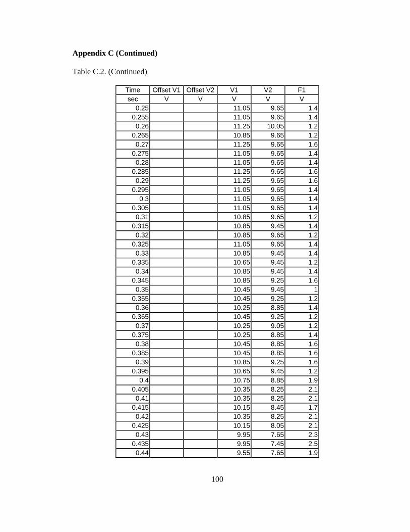
100
Appendix C (Continued)
Table C.2. (Continued)
Time Offset V1 Offset V2 V1 V2 F1 sec V V V V V
0.25 11.05 9.65 1.4 0.255 11.05 9.65 1.4
0.26 11.25 10.05 1.2 0.265 10.85 9.65 1.2
0.27 11.25 9.65 1.6 0.275 11.05 9.65 1.4
0.28 11.05 9.65 1.4 0.285 11.25 9.65 1.6
0.29 11.25 9.65 1.6 0.295 11.05 9.65 1.4
0.3 11.05 9.65 1.4 0.305 11.05 9.65 1.4
0.31 10.85 9.65 1.2 0.315 10.85 9.45 1.4
0.32 10.85 9.65 1.2 0.325 11.05 9.65 1.4
0.33 10.85 9.45 1.4 0.335 10.65 9.45 1.2
0.34 10.85 9.45 1.4 0.345 10.85 9.25 1.6
0.35 10.45 9.45 1 0.355 10.45 9.25 1.2
0.36 10.25 8.85 1.4 0.365 10.45 9.25 1.2
0.37 10.25 9.05 1.2 0.375 10.25 8.85 1.4
0.38 10.45 8.85 1.6 0.385 10.45 8.85 1.6
0.39 10.85 9.25 1.6 0.395 10.65 9.45 1.2
0.4 10.75 8.85 1.9 0.405 10.35 8.25 2.1
0.41 10.35 8.25 2.1 0.415 10.15 8.45 1.7
0.42 10.35 8.25 2.1 0.425 10.15 8.05 2.1
0.43 9.95 7.65 2.3 0.435 9.95 7.45 2.5
0.44 9.55 7.65 1.9
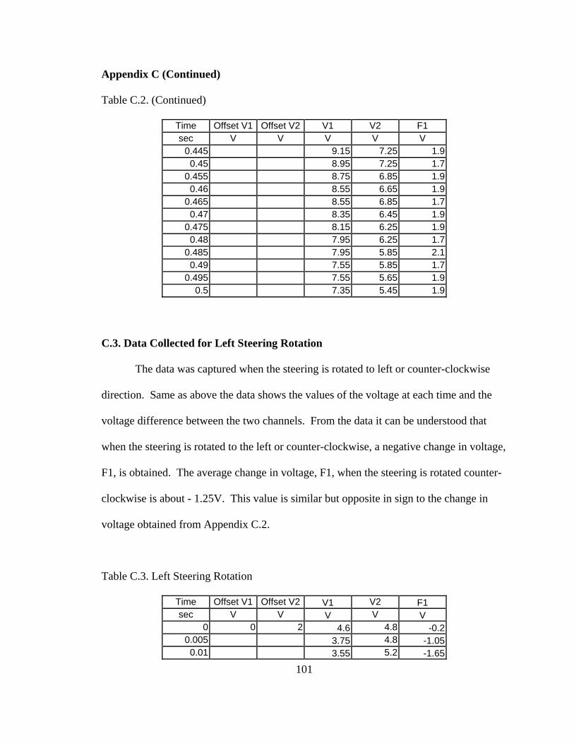
101
Appendix C (Continued)
Table C.2. (Continued)
Time Offset V1 Offset V2 V1 V2 F1 sec V V V V V
0.445 9.15 7.25 1.9 0.45 8.95 7.25 1.7
0.455 8.75 6.85 1.9 0.46 8.55 6.65 1.9
0.465 8.55 6.85 1.7 0.47 8.35 6.45 1.9
0.475 8.15 6.25 1.9 0.48 7.95 6.25 1.7
0.485 7.95 5.85 2.1 0.49 7.55 5.85 1.7
0.495 7.55 5.65 1.9 0.5 7.35 5.45 1.9
C.3. Data Collected for Left Steering Rotation
The data was captured when the steering is rotated to left or counter-clockwise
direction. Same as above the data shows the values of the voltage at each time and the
voltage difference between the two channels. From the data it can be understood that
when the steering is rotated to the left or counter-clockwise, a negative change in voltage,
F1, is obtained. The average change in voltage, F1, when the steering is rotated counter-
clockwise is about - 1.25V. This value is similar but opposite in sign to the change in
voltage obtained from Appendix C.2.
Table C.3. Left Steering Rotation
Time Offset V1 Offset V2 V1 V2 F1 sec V V V V V
0 0 2 4.6 4.8 -0.2 0.005 3.75 4.8 -1.05
0.01 3.55 5.2 -1.65
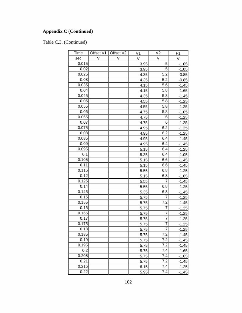
102
Appendix C (Continued)
Table C.3. (Continued)
Time Offset V1 Offset V2 V1 V2 F1 sec V V V V V
0.015 3.95 5 -1.05 0.02 3.95 5 -1.05
0.025 4.35 5.2 -0.85 0.03 4.35 5.2 -0.85
0.035 4.15 5.6 -1.45 0.04 4.15 5.8 -1.65
0.045 4.35 5.8 -1.45 0.05 4.55 5.8 -1.25
0.055 4.55 5.8 -1.25 0.06 4.75 5.8 -1.05
0.065 4.75 6 -1.25 0.07 4.75 6 -1.25
0.075 4.95 6.2 -1.25 0.08 4.95 6.2 -1.25
0.085 4.95 6.4 -1.45 0.09 4.95 6.4 -1.45
0.095 5.15 6.4 -1.25 0.1 5.35 6.4 -1.05
0.105 5.15 6.6 -1.45 0.11 5.15 6.6 -1.45
0.115 5.55 6.8 -1.25 0.12 5.15 6.8 -1.65
0.125 5.55 7 -1.45 0.14 5.55 6.8 -1.25
0.145 5.35 6.8 -1.45 0.15 5.75 7 -1.25
0.155 5.75 7.2 -1.45 0.16 5.75 7 -1.25
0.165 5.75 7 -1.25 0.17 5.75 7 -1.25
0.175 5.75 7 -1.25 0.18 5.75 7 -1.25
0.185 5.75 7.2 -1.45 0.19 5.75 7.2 -1.45
0.195 5.75 7.2 -1.45 0.2 5.75 7.4 -1.65
0.205 5.75 7.4 -1.65 0.21 5.75 7.2 -1.45
0.215 6.15 7.4 -1.25 0.22 5.95 7.4 -1.45
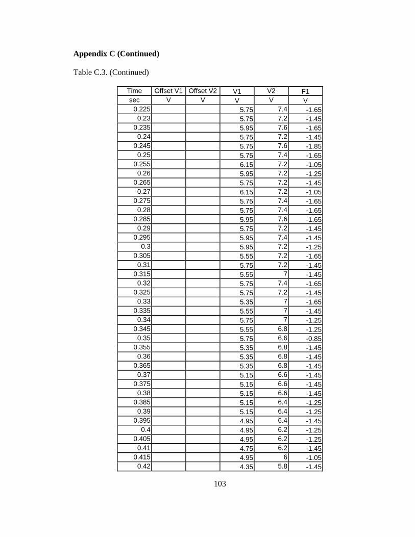
103
Appendix C (Continued)
Table C.3. (Continued)
Time Offset V1 Offset V2 V1 V2 F1 sec V V V V V
0.225 5.75 7.4 -1.65 0.23 5.75 7.2 -1.45
0.235 5.95 7.6 -1.65 0.24 5.75 7.2 -1.45
0.245 5.75 7.6 -1.85 0.25 5.75 7.4 -1.65
0.255 6.15 7.2 -1.05 0.26 5.95 7.2 -1.25
0.265 5.75 7.2 -1.45 0.27 6.15 7.2 -1.05
0.275 5.75 7.4 -1.65 0.28 5.75 7.4 -1.65
0.285 5.95 7.6 -1.65 0.29 5.75 7.2 -1.45
0.295 5.95 7.4 -1.45 0.3 5.95 7.2 -1.25
0.305 5.55 7.2 -1.65 0.31 5.75 7.2 -1.45
0.315 5.55 7 -1.45 0.32 5.75 7.4 -1.65
0.325 5.75 7.2 -1.45 0.33 5.35 7 -1.65
0.335 5.55 7 -1.45 0.34 5.75 7 -1.25
0.345 5.55 6.8 -1.25 0.35 5.75 6.6 -0.85
0.355 5.35 6.8 -1.45 0.36 5.35 6.8 -1.45
0.365 5.35 6.8 -1.45 0.37 5.15 6.6 -1.45
0.375 5.15 6.6 -1.45 0.38 5.15 6.6 -1.45
0.385 5.15 6.4 -1.25 0.39 5.15 6.4 -1.25
0.395 4.95 6.4 -1.45 0.4 4.95 6.2 -1.25
0.405 4.95 6.2 -1.25 0.41 4.75 6.2 -1.45
0.415 4.95 6 -1.05 0.42 4.35 5.8 -1.45
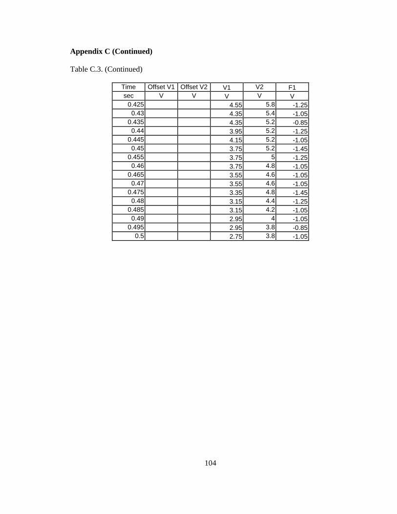
104
Appendix C (Continued)
Table C.3. (Continued)
Time Offset V1 Offset V2 V1 V2 F1 sec V V V V V
0.425 4.55 5.8 -1.25 0.43 4.35 5.4 -1.05
0.435 4.35 5.2 -0.85 0.44 3.95 5.2 -1.25
0.445 4.15 5.2 -1.05 0.45 3.75 5.2 -1.45
0.455 3.75 5 -1.25 0.46 3.75 4.8 -1.05
0.465 3.55 4.6 -1.05 0.47 3.55 4.6 -1.05
0.475 3.35 4.8 -1.45 0.48 3.15 4.4 -1.25
0.485 3.15 4.2 -1.05 0.49 2.95 4 -1.05
0.495 2.95 3.8 -0.85 0.5 2.75 3.8 -1.05
105
Appendix D: Disabilities and Driving Facts
As mentioned many times driving is a cherished part of everybody’s daily life.
However persons with disability have limitation in their driving needs and they require
some special assistance in their driving activities. As there are different types of
disability, a specific need is required for a particular type of disability. Before a vehicle
has been modified, a thorough study should have been undergone by the rehabilitation or
occupational therapist to determine what type of disability the person has and what
driving aide is important for modifying their needs. The following sub-chapter discusses
different types of disability and their driving needs after evaluation has been made by
driver rehabilitation specialist.
The factors of disabilities and its effect on driving for certain populations are
presented in the sections to follow. This information is excerpted from the Association
for Driver Rehabilitation Specialists, “Disabilities and Driving Fact Sheets” [14] and
from “Vehicle Adaptation for Disabled People Code of Practice”
http://www.equalityhumanrights.com/Documents/Disability/Transport/Vehiclerental.doc
[21].
D.1. Aging and Driving
As we all age, changes occur in physical functioning, vision, perception, and
processing abilities that could make driving unsafe. While changes are inevitable, they
occur at different rates in each individual, and age alone is not a good indicator of driving
skills [14]. Most often these changes occur slowly over a long period of time, and the
106
Appendix D (Continued)
individual is able to compensate for minor deficits. If several skill areas are affected, or
there is a sudden change in abilities due to illness or disease, driving may become
impaired. An evaluation is recommended if the person has a noticeable warning signs of
any the following:
• Doesn't observe signs, signals, or other traffic
• Needs help or instructions from passengers
• Slow or poor decisions
• Easily frustrated or confused
• Frequently gets lost, even in familiar areas
• Inappropriate driving speeds (too fast or too slow)
• Poor road position, or wide turns
• Accidents or near misses
A driver rehabilitation specialist can provide a comprehensive evaluation and
make recommendations regarding driving based on the following assessment:
• A review of medical history and medications
• Functional ability
• Vision
• Perception
• Reaction time
• Behind-the-wheel evaluation [14]
107
Appendix D (Continued)
D.2. Driving and Alzheimer's or Dementia
Deciding if and when it is time to stop driving is an extremely difficult and
emotional time. When Alzheimer's or dementia occurs, a decision will need to be made
as to when an individual is no longer capable of operating an automobile safely. The
individuals' independence needs to be measured against the potential hazards to
themselves, and the community. “Studies conducted using driving simulators have
detected that demented patients had more driving problems than non-demented elderly
controls” [14].
An evaluation by the driver rehabilitation specialist can be of great value in
helping to make this difficult decision. A driver evaluation will assess the components of
driving that may be compromised by this progressive condition. Areas assessed should
include: attention, processing speed, visuospatial functioning, decision making,
judgment, planning, memory, and behavior [14].
An evaluation is recommended when a diagnosis or problems first arise.
Compensatory strategies can be used to help maintain safe driving, and to set limits in
preparation for the inevitable. Discussing the issue, and planning for the future, is
important to do while the individual has the insight needed to participate. There are
warning that needs to be considered when the person is to be evaluated who have some
disability and those warnings include:
• Driving too slowly
• Doesn't observe signs or signals
• Difficulty interpreting traffic situations and predicting changes
108
Appendix D (Continued)
• Failure to yield
• Easily frustrated or confused
• Frequently gets lost
• Needs instructions from passengers [14]
D.3. Driving After a Traumatic Brain Injury
Traumatic Brain Injury (TBI) and Closed Head Injury commonly occur due to
motor vehicle collisions. Injuries can range from a loss of consciousness of less than five
minutes to being comatose for many months [14]. Any level of injury can cause an
increase in pre-injury bad driving behaviors or create new, unsafe driving issues. These
issues can stem from problems with vision, accuracy and speed of eye movements, speed
of response, attention, memory, problem solving, judgment and/or loss of physical skills.
It can spare one skill and wipe another skill completely from memory. It commonly
makes learning new information difficult and may keep a survivor from quickly learning
from their mistakes. All of the above can result in unsafe driving encounters,
unpredictable driving actions or repeat collisions for the survivor. Warning signs for
someone who has been in an accident or has had a TBI:
• Inappropriate driving speeds
• Is slow to identify and avoid potentially hazardous situations
• Needs help or instruction from passengers
• Doesn't observe signs or signals or speed limits
• Leaves out important road, traffic or warning information
109
Appendix D (Continued)
• Slow or poor decisions to traffic or road changes
• Easily frustrated or confused
• Pattern of getting lost, even in familiar areas
• Collisions or near misses
• Blames their driving mistakes on the behavior of other drivers [14]
D.4. Driving After a Spinal Cord Injury
The ability to drive a motor vehicle is a fundamental skill that influences various
aspects of daily functioning and independent living status. For the individual with spinal
cord injury, the inability to drive a car can significantly hinder return to employment and
participation in community activities. After a spinal cord injury has occurred, a person is
no longer able to drive an automobile in the normal manner. However, there are several
types of adaptive equipment and vehicle modifications that can allow an individual with a
spinal cord injury to drive. Depending on the level of injury and functional ability, either
a sedan or van may be an appropriate vehicle choice and there are some considerations
for selecting a vehicle. When considering the use of driving a sedan, the individual must
be able to do the following:
• Lock and unlock the door
• Open and close the door
• Transfer to and from the wheelchair
• Store and retrieve the wheelchair (either independently or with a wheelchair
loading device)
110
Appendix D (Continued)
If an individual is unable to drive a sedan, there are several options available for
driving a van. Specialized modifications can allow a person to transfer to the driver seat
or to drive from the wheelchair. There are several levels of driving control technology to
compensate for the loss of strength and/or range of motion where some include:
• Reduced-Effort steering systems to compensate for reduced strength
• Servo brake and accelerator control to compensate for reduced range of motion
and strength
• Joystick driving systems, allowing one hand operation of brake, accelerator and
steering
Adaptive equipment and vehicle modifications for wheelchair access are available
for some full-size and mini vans; however, all vans are not suitable for modifications. A
driver rehabilitation specialist can assist in making the correct van choice. He/she can
provide a comprehensive evaluation to determine a person’s ability to drive. The
Assessment should include: Vision perception, functional ability, reaction time, and a
behind- the-wheel evaluation [14].
D.5. Driving with Rheumatoid Arthritis
Rheumatic disease includes nearly 100 different conditions, which cause pain in
the joints and connective tissue throughout the body. The key factor in the most serious
forms of rheumatic disease is inflammation evidence by heat, swelling, redness, stiffness,
and pain. Depending on the areas affected and functional ability, either a sedan or van
may be an appropriate vehicle choice. Loss of joint mobility may result in diminished
111
Appendix D (Continued)
ability to reach, grasp, manipulate, and release objects. Strength, endurance, and range of
motion difficulties may necessitate adaptive devices: such as extra mirrors, key holders,
extended gear shift levers, power windows and door locks. More extensive adaptive
equipment or vehicle modifications may be needed for persons whose ability to use their
arms and legs is severely affected by the disease. Same as driving after spinal injury there
are some considerations to be taken for selecting a vehicle.
When considering the use of driving a sedan the individual must be able to do the
following task in order to be recommended by occupational therapist.
• Lock and unlock the door
• Open and close the door
• Transfer to and from the wheelchair if applicable
• Store and retrieve the wheelchair (either independently or with a wheelchair
loading device)
Since characteristics and dimensions of vehicles vary, it is important that the
individual performs these functions in the vehicle being considered prior to purchase. A
driver rehabilitation specialist can provide recommendations for sedan selection.
If an individual is unable to drive a sedan, there are several options available for
driving a van. Specialized modifications can allow a person to transfer to the driver seat
or to drive from the wheelchair. There are several levels of driving control technology to
compensate for the loss of strength and/or range of motion:
• Reduced-Effort steering systems to compensate for reduced strength
112
Appendix D (Continued)
• Servo brake and accelerator control to compensate for reduced range of motion
and strength.
• Joystick driving systems, allowing one hand operation of brake, accelerator and
steering [14].
D.6. Driving with Multiple Sclerosis
Multiple Sclerosis can affect individuals in varying ways including tingling,
numbness, slurred speech, blurred or double vision, muscle weakness, poor coordination,
unusual fatigue, muscle cramps, bowel and bladder problems and paralysis. Due to these
symptoms, special equipment or accommodations may need to be made to aid a person in
safely maintaining their mobility independence for as long as possible. During selecting
a vehicle there are physical considerations to look for, i.e. when selecting a van for
driving the individual must be able to do the following:
• Open and close the door
• Transfer in and out of the vehicle
• A wheelchair or scooter must be able to be stored and retrieved. Special
equipment is available to aid with storage
Options may include a mini-van with a lowered floor and a ramp or a full size van
with a lift. Specialized modifications allow a person to transfer to the driver's seat or
drive from a wheelchair. Technology may be able to compensate for the loss of strength
or range of motion such as:
• Reduced-Effort steering and/or brake systems to compensate for reduced strength
113
Appendix D (Continued)
• Mechanical hand controls allow for operation of the gas and brake using upper
extremities
• Servo brake/ accelerator systems compensate for reduced strength/range of
motion of arms
• If spasticity is difficult to manage, it may lead to an inability to drive [14]
D.7. Driving After a Limb Amputation
After a limb amputation, a person is sometimes unable to drive an automobile in
the normal manner. There are, however, several types of adaptive devices that can allow
an individual with an amputation to safely resume driving. The site of amputation(s) will
determine the degree of difficulty an amputee will have with driving a standard equipped
vehicle. In most cases, the adapted equipment will involve compensation for the inability
to reach and operate primary and secondary driving controls. Person with specific type
of limb amputation their vehicle is adapted on their specific needs.
For a right leg amputation the equipment which is necessary to adapt includes:
• Left foot gas pedal
• Automatic transmission
• Power braking
For a left leg amputation the equipment which is necessary to adapt includes:
• Hand controls for brake and accelerator spinner knob
• Automatic transmission
• Hand operated dimmer switch
114
Appendix D (Continued)
• Emergency Brake Extension
• Chest strap
For an upper extremity amputation the equipment which is necessary to adapt
includes:
• Automatic transmission
• Steering device
• Reduced effort steering
• Modified gear shifter
• Modified secondary controls (turn signals, dimmers)
For a triple or quadruple amputation the equipment which is necessary to adapt
includes:
• Additional modifications can be made to car or van
• Reduced effort steering system
• Servo brake and accelerator control
• Joystick driving systems [14]
D.8. Driving After a Stroke
Driving is viewed not just as a 'privilege' but also as a necessity. When a stroke
occurs it can affect the skills necessary for independent driving. A majority of stroke
survivors can return to independent driving. The goal is to maintain safe and independent
driving for as long as possible [14]. Driving ability has been assessed differently. The
most common method has been driving in real traffic. Another method has been to use a
115
Appendix D (Continued)
driving simulator, in which the driving situation can be standardized, but is not quite as
realistic as real traffic driving [21].
Adaptive equipment is frequently used for physical problems. A spinner knob
can be attached to the steering wheel to allow controlled steering with the use of one
hand. A left gas pedal may be used if you are unable to use your right foot to gas or
brake. Training is essential with any equipment to be safe with your new adapted driving
method [14]. There are a warning signs that can be important to look for after having a
stroke and a rehabilitation specialist can determine if the person has some of those sign
which includes:
• Inappropriate driving speeds (too fast or too slow)
• Needs help or instructions from passengers
• Doesn't observe signs or signals
• Slow or poor decisions (poor judge of distances, too close to other cars)
• Easily frustrated or confused
• Pattern of getting lost, even in familiar areas
• Accidents or near misses
• Drifting across lane markings, into other lanes
Noticing any of the above warning signs require a driver evaluation. A driver
rehabilitation specialist can provide a comprehensive evaluation to determine the ability
to drive [14].
116
Appendix D (Continued)
D.9. Driving and Spina Bifida
Spina Bifida is a congenital defect in which part of one or more vertebrae (the
bone structure that surrounds the spinal column), fail, to develop completely, leaving part
of the spinal cord exposed. It can occur anywhere on the spine but is most common in
the lower back. The severity of the condition depends on how much nerve tissue is
exposed. Frequently special adaptations on a vehicle are necessary for independent
driving. The person with spina bifida may also have impairments in the areas of vision,
perception (how the brain interprets what the eyes see) or learning [21].
Adaptive driving equipment is frequently used for physical problems. A spinner
knob and hand controls can be used if a person is unable to use either foot for gas or
brake. Specialized modifications can also allow a person to transfer to the driver's seat or
drive from the wheelchair in a van or minivan where common factors that can affect safe
driving are:
• Limited range of motion and strength
• Difficulty with coordinated movements
• Visual impairments (poor acuity)
• Trouble visually scanning or tracking quickly
• Learning difficulties
• Impaired judgment in complex situations
• Slow processing and reaction time
A driver rehabilitation evaluation will examine the strengths and weaknesses of
each individual as related to the driving task. The goal is independent, safe driving. No
117
Appendix D (Continued)
modifications or vehicle selection should be made until the person has completed a driver
evaluation and the assessment should include:
• Vision
• Perception
• Functional ability
• Behind-the-wheel evaluation [14]
D.10. Driving and Cerebral Palsy
Cerebral Palsy (CP) applies to a number of non-progressive motor disorders
present from birth. The involvement varies widely from person to person. The person
with CP may or may not be a wheelchair user. Frequently special vehicle adaptations are
necessary for independent driving. The person with CP may also have impairments in
the areas of vision, perception (how the brain interprets what the eyes see) or learning.
Adaptive equipment is frequently used for physical problems. A spinner knob
can be attached to the steering wheel to allow controlled steering with the use of one
hand. A left gas pedal may be used if a person is unable to use the right foot for gas or
brake. Hand controls may be indicated for the person unable to use either foot for gas or
brake. Specialized modifications can also allow a person to transfer to the driver seat or
drive from the wheelchair in a van or minivan with common factors that can affect safe
driving:
• Limited range of motion and strength
• Exaggerated startle reflex to loud noise
118
Appendix D (Continued)
• Increased muscle tone
• Difficulty in coordinated movements
• Visual impairments (poor acuity)
• Trouble visually scanning or tracking quickly
• Learning difficulties
• Impaired judgment in complex situations
• Slow processing and reaction time
A driver rehabilitation evaluation will examine the strengths and weaknesses of
each individual as related to the driving task. The goal is independent, safe drive. No
modifications or vehicle selection should be made until the person has completed a driver
evaluation where the assessment should include:
• Vision
• Perception
• Functional ability
• Reaction time
• Behind-the-wheel evaluation [14]
D.11. Driving and Attention Deficit Hyperactivity Disorder
Attention Deficit Hyperactivity Disorder (ADHD) commonly becomes evident in
early childhood and probably will be chronic in nature. The disorder consists of
developmental deficiencies that can range from inhibiting behaviors to initiating and
119
Appendix D (Continued)
sustaining behaviors. The individual may improve with age. Any level of ADD or
ADHD may increase the risk of unsafe driving issues. These issues stem from under
developed visual perception skills, impaired ability to self-regulate behavior, moods and
responses. Lack of organization and the inability to concentrate are also underlining
issues. Their ability to learn information for the licensing knowledge test works well
when one on one instruction is provided. Learning from their driving mistakes takes
extra time. All of the above can result in unsafe driving encounters, unpredictable
driving actions or an increased number of "minor" accidents and there are warning signs
that interfere safe driving:
• Doesn't observe signs/signals
• Drifting while driving
• Failure to yield right of way
• Difficulty with interpreting traffic environments / does not anticipate dangerous
situations
• Impaired eye/ hand/foot coordination
• Neglects to observe all areas of the vehicle before driving in reverse
• Multiple minor accidents
• Slow to respond to traffic lights
• Speed fluctuation / Inappropriate speeds
• Unable to coordinate distractions and driving


![Electromechanical Virtual Simulator CT QA Image quality Quality Management Program ... trouble in paradise VSim hosts file ... Microsoft PowerPoint - 49-14445-40528-950.ppt [Read-Only]](https://img.pdfslide.us/doc/110x75/5afc93ef7f8b9a444f8c3b19/electromechanical-virtual-simulator-ct-qa-image-quality-quality-management-program.jpg)