Embed Size (px)
Citation preview

54 Junhu a Teng e t al.; An Efncic lll Algori thm for Raster-l o-Vec tor Data COil vers ion
An Efficient Algorithm for Raster-to-Vector Data COllversion
JunhU3 Tengl, Fahui W:mgl, Yu Liu J
! Sla te Key Labor:uory of Sate lli te Ocean Env ironment DYIl<l mics, Seco nd Insti tu te of Oceanography, Slate Occ,mic Admi ni s tr:llion , H:lllgzhou.31 00 t 2, C hina
E-mail: htgis@163 .com ~ Department of Geogmphy and Anthropology, Loui siana Slate Univers it y. Balon Rouge , LA 70803, USA;
3 Insti tute o r Remot e Sensing and Geographic:!l Informat ion Systems, Peking University. Beijing t 0087 1. China
AbslTact Data conversion from (liste r 10 vector (R2V) is a key function in Geographic lnformat ion Systems (GIS) and remote sensing (RS) image process ing for integrating GIS and RS data. The R2V module is avai lable in commercial RS software packages, but there is still room to improve the computat ion effic iency. This paper presents an efficient R2V algorithm that processes large imnges and automati call y builds GIS topology wh ile scanning image lines one by one. The new algorithm, tenned Two-Arm Chains Edge Tracing (TACET), has severa l significmlt advruHages. First, it converts all types of area objec ts of RS class ification in only one process ing cycle. Secondly, it conslnicts complete area topological relationsilip by recording the shared edge between two polygons onl y once. Finally, it is scalable when process ing large images. The program based on the algorithm is faster in process ing large RS images with comparison to commercial software sllch as ENVl. Keywords rasler to vector, data cOllversion, Two-Ann Chains Edge Tracing (TACET) algorithm, LilfleHuskie R2V
I. INTRODUCnON
RaSler to vector (R2V) data convers ion or veetoriZa/ioll is a key function in geographical information systems (GIS) and remote sensing (RS) image processing for data integration between RS and GIS (Mallikalli , el aI. , 1995). Tn general, there are two types of R2V algoril lull , namely line vectorization and polygon vectorizntion. Line veetorizatioll is often lI sed in CA D for di gita liz ing im ngcs from pnper medin, e.g., ext rnct illg conto ur lines from scanned topogrnph.ic maps. During thi s process, linear elements on n map are automatically recogn ized nnd represented in a vec tor formnt. Numerous algorithms of line vectorization are developed, and mnny software pnckages s lI c h as A lgoLab (htt p ://www.n lgo lnb.co mlr2v. htm ). RasterVect (httpJ/www.nJstervec t.com) and Scan2CAD (http: / /www.softcover.com) nre available to cnter the Inrge CA D nnd art des ign mnrke ts. Polygon vee/ariza/ion is often used in extract ing geographical features from RS imagelY clnssificntion result s. One npplication of polygon vec tori zation is to update lnnd use databnse from RS data. This pape r focllses on polygon vectorizat ioll .
Severa l important ex isting studies all polygon vec torization a re hi g h I ighted he re. Congaiton (1997) d isc nssed the impoI1ance of R2V or V2R in theory, and explored nnd evnhmted the outcomes of R2V and V2R convers ions. Lou et al. (2005) disc ll ssed the problem of R2V COil version based on classified remote sensing images, and recogni zed the difficulties of hand ling all classes of geographical objects s imultaneous ly in the process. Riekert (1993) proposed a n a lgor ithm of extrac ting aren objects from raster image data, which proved to be sign ificlUlt improvements over previous algorithms. At present , the R2V module is included in many RS software packnges such ns ENVI. However, there is still room to improve
the algorithm to enhnnce its pelformance. This research buiJds upon th e work by Ri ekert ( 1993) and makes rnrth e r improvements and clarifi cations. Its adva nlnges become evident in hnndling complex large imnges .
The R2V convers ion is nn important tnsk for nt least three reasons as explained in the following.
• R2V is a time-consuming process nnd de mands hi gh computing power. The fnster the nlgorithm is, the larger image it can handle. Genernlly, the time complexity of a R2V algorithm is 0(11*111) , where n nnd III denote the size of an imnge, because ench pixel needs to be accessed nt leas t once to be determined whe the r it is a node or n vel1ex.
• The speed of n R2V algorithm is also detennincd by spntial compl ex it y. As the resolution of an image becomes sharpe r, the dnta vol ume increases. This may e ither significantly slow down the display of an image or prevcnt it from bei ng w holl y loaded due to limited computer cnpncity. It is crilicnlto find an approach with reduced spat inl complexity.
• In order to make R2V results ready for GIS users, it is desirable for the vector dntn to contnin nll types of classification in one fil e inslend ofmulliple files with each type snved ill one single file. It is also more convenient to manage the comple te topologicnl relati onship among classes. RS dnta have become a fnst and convenient source for updating spntinl databnse. Take land use c hanges ns an exnmple. If nll land use c1 nssificat ions me saved in one da ta se t w ith topology, it is easy to edit one area nnd maintnin consistency in ndj ncent arens.
1082-4006/08/ 14(0 1)-54$5.00 <02008 The Internat ional Associat ion of Chinese Professional s
in Geographic Information Science (CPGIS)
Geograph ic Informati on Sciences Vol. 14, No. I. June 2008 55
Il. BASIC CONCEPTS IN R2V ALGORITHM
As di scussed in the prev ious section , R2 V in clu des line vectorization and polygon vec torizatioll. Line vectoriza tion focll ses on Line thinnjng by converting bold lines in a digital scanned image into skele ton lines. This paper focuses o n polygon vectori za tion. Polygon vectorizatioll may be also related to line vectorizat ion . For instance, one may use line vectorization to ex tract polygon edges fi rst, and then export the de ri ved edges into a GIS soft ware package for fmther processing. However, this approach is rarely used because of its low transformation accuracy and efficiency. In contrast to line vectorization where line features nre extracted based on ce nte r points of pixe ls, polygo n vcc tori zati on de fine s boundaries by edges between pixels.
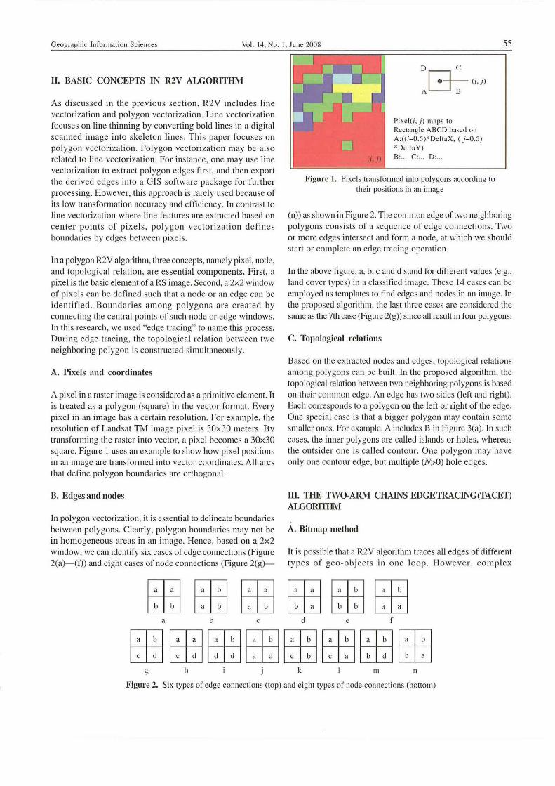
In a polygon R2V algorithm, three concepts, namely pixel, node, and topological re lation, are essential components. First, a pixel is the basic element of a RS image. Second, a 2x2 window of pixels can be defin ed such that a node or an edge can be id entifi ed . Boundaries amon g polygons are created by connecting the central points of such node or edge windows. in this research, we Ll sed "edge tracing" to name this process. During edge trac ing, the topo logical relation between two neighboring polygon is constructed simultaneously.
A. Pixels find coordinates
A pixel in a raster image is considered as a pri.mitive element. It is trea ted as n polygon (square) in the vector format. Every pixel in an image has a certain resoluti on. For example, the resolution of Landsat TM image pixel is 30x30 meters. By transforming the raster into vector, a pixel becomes a 30x 30 square. Figure I uses an example to show how pixel positions in (Ul image are trrulsfonned into vec tor coordinates. All arcs that defi ne polygon boundaries are orthogonal.
B. Edges mId nodes
In polygon vec tori zation, it is essential to delineate boundaries between polygons. Clearly, polygon boundaries may not be in homogeneous areas in an image. Hence, based on a 2x2 wi ndow, we can identify six crises of edge cOlUlections (Figure 2(a)-(I)) and eighl cases of node conl1cctiol1s (Figure 2(g)-
GLJG:liJ GLJ ~
a b
GLJ LJiJ
c
(/ J)
D C
r:l-- C;,j)
A~
Pixel (i, j) maps to Rcc t,mgle ABe D based 0 11
A:«i-O.S)*DcltnX. (j- O.S) *Delta Y) B, .. C. D,.
Figure I. Pixe ls transformed into polygons according to their positions in an illlrtge
(n» mi shown in Figure 2. ThecOIlUllon edge of two neighboring polygons consists of a sequence of edge connections . Two or more edges intersect and form a node, at which we should start or complete an edge tracing operntion.
in the above figure, a, b, c and d stand for different values (e.g., land cover types) in a classLfi ed i.tnage. These i4 cases can be employed as templates to find edges and nodes in an image. In the proposed algorithm, the Inst three cases are considered the same as the 7th case (Figure 2(g» since aU result in fOllr polygons.
C. Topological relations
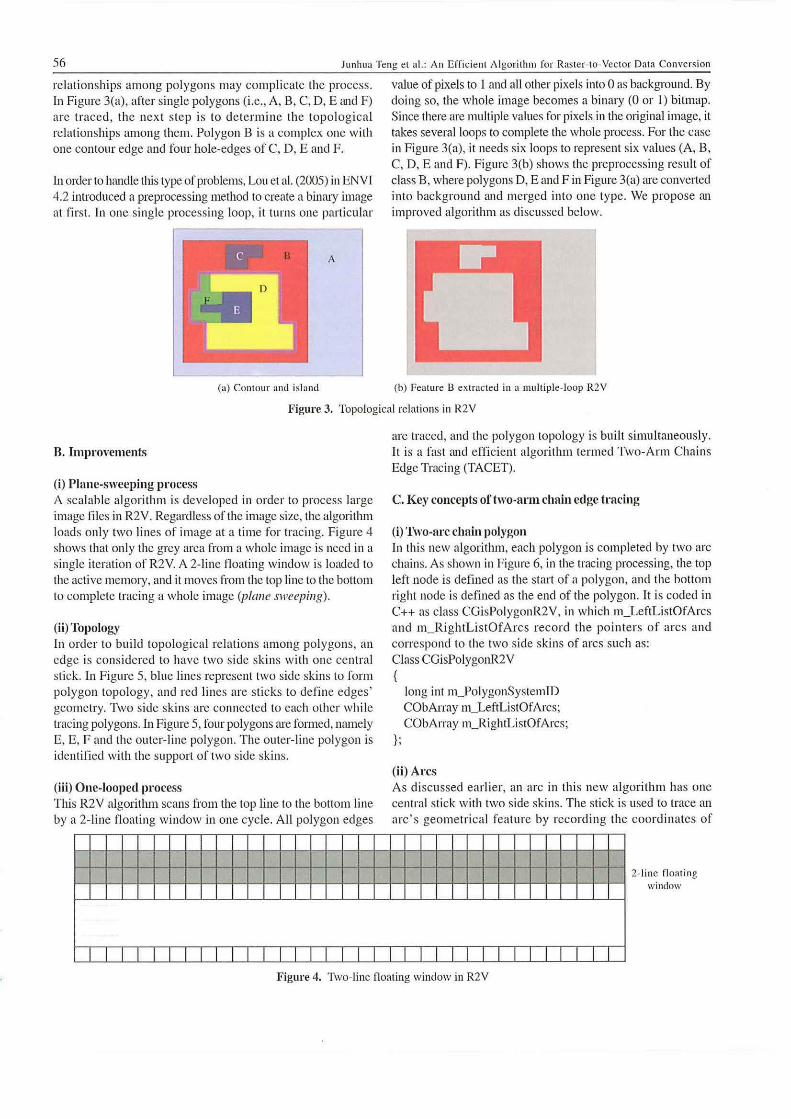
Based on the extracted nodes and edges, topological re lations among polygons can be built. In the proposed algOlithm, the topological relation between two neighboring polygons is based on their cOllllllon edge. An edge has two sides (left and right). Each cOlTesponds to n polygon on the left or right of the edge. One special case is that a bigger polygon may contain some smaller ones. For example, A includes B in Figure 3(a). [n slIch cases, the inner polygons are caUed islands or holes, whereas the ou tsider one is call ed contour. One polygon may have onl y one contour edge, but multiple (N;,O) hole edges.
ill. THE TWO·ARM CHAINS EDGETRACING(TACEf) ALGORfIHM
A. Bihnap method
It is possible that a R2V algorithm traces all edges of different types of geo-obj ec ts in o ne loop. However, complex
GLJ~~ ~~GLJ
d e r
G:liJGLJ~~~~~~ ~~~~GEJGLJ~~
g h k III 11
Figure 2. Six types of edge connections (top) nnd e ight types of node conncct ions (bottom)
56 lunhua Tcng el al.: An Efficient A lgori thm fo r Raster-I o-Vector Data CO I1\'ersion
re lationships among polygons may complicate the process. In Fignre 3(a), after single polygons (i.e., A, B, C, D, E and F) are traced, the nex t step is to determine th e topolog ical reinlionships among them. Polygon B is a complex one with one contour edge and four hole~edges of C, D, E and F.
[n order to handle this type of problellls, Lou et al. (2005) in ENVI 4.2 illlroduced a preprocessing method to create n binary image at first. In one single processing loop, it turns onc particular
8 A
(a) Contour and island
value of pixels to 1 and all other pixels into 0 as background. By doing so, the whole image becomes a binary (0 or 1) bitmap. Since there are multiple values for pixels in the OIiginal imnge, it takes several loops to complete the whole process. For the case in Figure 3(a), it needs six loops to represent six va lues (A, B, C, D, E and F). Figure 3(b) shows the preprocessing result of class B, where polygons D. E and F in Figure 3(a) are convel1ed into background and merged into one type. We propose an improved algorithm as di scussed below.
(b) Feat ure 8 ex tracted in a mu ltipl e-loop R2V
Figure 3. Topological relations in R2V
B. ImproYements
(i) Plane-sweeping process A scalable algorithm is developed in order to process large image fil es in R2V. Regardless of the image size, the algorithm loads only two lines of image at a time for traci ng. Figure 4 shows that only the grey area from a whole image is need in a single iteration of R2Y. A 2- line noating wi ndow is loaded to the active memory, and it moves from the top line to the bottom to complete tracing a whole image (plalle sweeping) .
(ii) Topology In order to build topolog ical relations among polygons, an edge is considered to have two side skin s with one central stick. In Figure 5, blue lines represent two side skins to form polygon topology, and red lines are sticks to defin e edges' geometry. Two side skins are connected to each other while tracing polygons. In Figure 5, four polygons are formed, namely E, E, F and the outer-line polygon. The ollter-line polygon is identified with the supp0l1 of two side sk ins.
(iii) One-looped process This R2V algoritlull scans from the top line to the bottom line by a 2- line n OtHing window in one cycle. All polygon edges
I I I I I I I I I I I
are traced, and the polygon topology is built simultaneously. It is a fast and efficient algorithm termed Two-Arm Chains Edge Tracing (TACET).
c. Key concepts of two-arl11 chain edge tracing
(i) 1\\'O-arc chain polygon In this new algorithm, each polygon is completed by two arc chains. As shown in Figure 6, in the tracing processing. the top left node is defined as the start of a polygon , and the bottom right node is defined as the end of the polygon. It is coded in C++ as class CGisPolygonR2V, in which I11_LeftListOfArcs and I11_RightListOfArcs record the po inters of arcs and correspond to the two side ski ns of arcs such as: Class CGisPolygonR2V {
};
long int l11]olygonSystel11lD CObArray Ill_LeftListOfArcs; CObArray I11_RighIListOfArcs;
(ii) Arcs As di sc llssed earlie r, an arc in this new algorithm has one central stick with two side ski ns. The stick is used to trace an arc's geometrical feature by recording the coordin ates of
I I I I I
2- lillc floating window
Figure 4. Two- line floating window in R2V

Geographi c Information Sc iences Vol. 14 , No . I t June 2008 57
D F
E
Bluc Line: Skin Red Line: Slick
OUler-Line pol ygo n
¥'
Figure 5. Two side skins tracing to fOfm polygon topology
left List or Arcs
A polygon i s {"Omplett"d by Iwo Arl' chains
Polygon ends ;\ t
the hOllom \...,--- " right node
Figure 6. 1\\'0 arc chains are lI sed ill polygon tnlc ing
vertices . The Iwo side skins, defined as le ft skin and right skin , are lIsed to trace polygons. \Vhcn one arc ends (e.g., :ll a node), its pointer is added to the polygon arc chains, i.e., the le ft skin is added to III_LeftListOfArcs and the right sk in to III_RightListOfArcs. The C++ codes are: Class CcsArc (
long int m_ArcSystemlD; CObAJTay m_ListOtVe,1exCo,Tdinate;
) ;
(iii)'l\vo-AI'IIl Chain A comprehensive class CHIArllls is lI sed to record the traci ngs of both arcs and polygons. Since the R2V algorithm is a planesweep process, the tracing is always from left to right in the horizontal direct ion and from top to bottom in the ve rtical direc tion. Figure 7 shows all member variab les in the class e NIAnu. Two arms are used to trace polygons and arcs : the vertica l ann 11I-1JArc VerlicalArm and the horizontal ann IJI..../JArcHor;ZolloIAnli . The concepts of virtual ann and solid ann are introduced here, if the pi xel has the same value with the above one, then the horizontal arlll "'..../JArcH orizol1aIArm is virtual, otherwise is solid, and in the same way, ir the pixel has the same value with the left one, the hori zontal ann l1I_pArcHor;zollaIArm is virhml, otherwise solid. Considering that the whole two-d imension space is divided into three PUliS by the two arms, three variables, namely I1I-pAbovePolygoll, 1lI_lll sidePo/ygol/ and fIJ--pLe!tPolygoll , are used to record
lIl_p Above Polygon
In_p Arc lIorillluli l Ann
c E 0
'" ..: ~
-0 " "- u Ill_p In side Polygon .;: ·c u ;';] oJ 0- e , « E 0-
I E
t Figure 7. An ill slance of CHIArlll class
th e above pol ygon, in sid e po lygo n and le ft pol ygon respectively. Con-esponding to Ihe side skins or arcs (i.e., arms), these polygons are necessa ry ro r building the topology simultaneously with edge traci ng. The variable III_Pixe/Value records a pixel's value (e.g. , land use type), and the variable lII_fCo/Pos records the pixe l' s columll pos ition. The C++ definition of the Two-Ann Chain class is: c lass CHtArm:public CObject ( pubHc:
) ;
long int long int CGisPolygonR2V CGisPolygonR2V CGisPolygonR2V CCsArc CCsArc
m_Pixe IValue; m_ICoIPos;
*m_ plnsidePolygon; *m_pAbovePolygon; *m_pLeft Polygon; *m_pArcVeliicaIArm; *m_pArcHorizonaIAnn;
D. Conllecting rules for two~al'm chains
Since topological relations among edges and polygons are built in each arm, the whole R2V process can be implemented by connecting the arms. This was not made clear in Riekert ( 1993). The followin g explains the connecting rules for the Two-Arm Chains algorithm .
(i) Rules for creating polygons Ln this new algorithm, a polygon is traceu by beginning rrom thc top left node and end ing at the bottom right node. It should be noted thm the o ll ter polygon is created when the last node (i.e., the bottom right pixel) of the whole image is reached.
(ii) Rules for passing topological relations among neighboring CHtArlll objects When tracing from olle arm to another from left to right and from top to bottom, topologicnl inrormation is passed between them. Two other two-arm objec ts (i.e., pTwv;\I'II1Previolls and

58 Jtlnhua Te ng el tt l. : An Efficient Algorithm for Rmacr· loNcc tor Data Conve rsion
pTwoAnl1Above) are considered in connecting the arms by fo llowing the fo llowing principles. First, the vertical arm of pTwoArlllPreviolts obje c t and the hori zo ntal arm of pTwoArl1lAbove object are ignored because the iteration goes from lefl to right and from lOp to bottom . Secondly. the sideskins information of each ann is inheri ted from its neighboring solid ann and passed 0 11 to the next arm across the virtual arm. Third ly. afte r conn ec ting the arm s, a ll horizon tal arm information in each two-arm object is transferred to the Ilext
solid ven ical arm, or terminated when the polygon is closed.
+ ... ~ :.: m p Two Arm Above
~--~:.:
.... ;·;· .. ;..111 ...... .... ....... "JIIlIIII""'"
t P Two Arm Prc\' ious P Two Arm Next
Ignored Ann
Figure 8 shows two typical examples out of II scenarios (fUJ1her illuslmled in Figure 9 and Figure 10). In Ihe leti gmph of Figure 8, the ve rtical and horizontal arms of pTlI'oAl"lIIAlJove object are both virtual. The "TlI'oArmPreviolls objec t passes its le ft side-skin informmion onto pTlI'oArl1lNexl, and pTwoA rl1lNex/
also inherits the right side-skin infollllalion from ils neighboring solid arm of pTlI'oA nllPrevio/ls objecl. The corresponding transferring nile is: pTwoAnnNext-> lll_pAbove Polygon = pTwoAnnPreviolls-> ll1_pAbovePolygon
. . . ~ P Two A rm Above
Polygon cI~~ ~ .. ...... ....... ~" "" '''JIIII'''''"
t P Two Arm Prc\·iotls p Two AntI Nex t
Vi rtllu] Arm Solid Arm
Figul'e 8. Two typical eXilmples o f passing topolog ical relations between arms
(a) Prior li ne
(b) Two-Arm Ch:1in of prior line
(c) Curren t line
(e1) Two-Arm Chain of Curren! line
(e) Add E:ma Two-Arm Chains based on prior line
(r) Run-Length Code Tracing Ed ges(TwoArm e lwin Creati ng)
(g) Con nec ting Two-A nn Chain o f prior line
Line scann in g direction
rrrr
Figul'e 9. Edge trac ing while creating two-arm chain

Geogmphic In format ion Sciences Vol. 14 . No. I, June 2008 59
•
(a)
1 ~ ....
(e)
1 • ~
.. (i)
•
.. ...... ~
~ •
+
i (d)
r
·1 (II) , t . ................... .--~~ ,
+ .. i-U) (k) (t)
1 1 1 • ~ • ~ . . ~ • +--........ .. ... ~ • .. -.... ~ .-.- ~ .-........... ~ ................ ~
~ ~ ~ + (m) (n) (0) (p)
Figure 10. 16 poss ible scenarios ofl\vo-Arm Chains conneclions
pTwoAnnNext-> m_plnsidePolygon = pTwoAnnPreviolls-> m_pAbovePolygon pTwoArmNext-> lll_pLeftPolygon = pTwoAnnPrev iolis-> m_plnsidePolygon; In the right graph of Figure 8, the left side-skin info rmation of p1'woArlllPrevious object and the right side-skin information of pTI\!oArIl1Ahove are terminated because of closing of the polygon at the bottom right, i.e., the end of polygon tracing. Its left side-skin information is inherited from p7l\IoArIl1Above, and its right side-ski n information from its neighboring pTwoArl1lPreviolis object. Here a11 horizontal arms information is transferred into vel1ical arms.
E. RlIl~s foJ' connecting arcs to form a polygon
If nodes are met during the process of connecting two-ann objects, the correspond ing arc tracing is completed. AI this time, the CCsAre object should be saved and assigned to the resulting polygon. [fthe endi ng arc object is a horizontal ann, the left side skin is appended to the left arc chai n of the II1--1JAbol'ePo/ygoll object of current two-arm object, and the ri ght side skin is appended to the right arc chain of the
J11-plllsitiePoiygoll object of current two-arm object. If the ending arc object is a vertica l ann, the right side skin is appended to the right arc chain of the III...JJLeJrPolygoll object of current two-arm object, and the left side skin is appended to the left arc chain of the lII-pillsidePolygoll object of current two-arm object (also see Figure 7).
F. Implementing the two-arm chain edge tracing (TACET) algorithm
(i) Edge tracing based oulhe (wo-ann chain algorithm Figure 9 shows the edge tracing procedures based on the Two-Arm Chain al gorithm. Fi gure 9(a) illu strates the distribution of pixel s in the top line of an image. Because of the Illap boundary. the corresponding arcs are aU solid except for the last one (as shown in Figure 9(b». Figure 9(c) shows the distribution pattern of pixels in the next line, and Figure 9 (d) is the derived Two-Arm Chains. In Figure 9(d), two TwoArm objects have viltual horizontal arms because of the same pixel values C and A as in the prior line. As the Two-Arm objects in the prior linc( in Figure 9(b» have to be inherited, extra Two-Ann objects are added inlO current line (Figure 9

60 Junhua Teng et al.: An Effi cie nt Algo rithm for Ras ter-(Q-Vcctor Data Co nversio n
Cd» though these objects have the virtual vertical arms. As showll in Figure 9(e), the blue ones are inherited fromlhe prior chain. As a pixel's position in each arm (represented by class CHtAnn ) is saved in the member variabl e 1II _ICo/Pos, the hori zontal edges can be formed by recording the rUllningle ngth codes accordin g to its conti guous CJ-JtAnn objects. For example, 1II_l\lo/Pas is 0 in the first CHfAnn object, ,Uld III_lCD/Pas is 2 in the second CHtA1'I1I object. Therefore, the horizontal edge is from 0 to 2 along the horizontal axis. Figure 9([) shows the complete chains' information , where solid arms arc represented as solid lines and viliunl al111 5 are dashed lines. As discll ssed in the next subsection , solid and virtual arms play different roles in connecting arms. Figure 10(g) shows how two Two-Arm Chai ns (one shown in Fi gure 9(b) and another in Figure 9(f)) nre cOllnected. If 110 corresponding Two-Arm objects exist between Figures 9(b) Imd 9(0, extra Two-Ann objects wi th vil1ual vCI1icai arms are created similarly.
(ti ) '1\vo-AI'JIl Chaills COIll1eCnOn Analysis During the above process of cOllnecting the Two-Arm Chains, polygons are nl so c rented. 11 valid cases can be identifi ed from 2..\ (=16) possible scenarios. In Fi gure 10, solid lines represent cases when two nei ghboring pixels have different values , and dashed lines represent two neighborin g pi xels with the same va lues.
In Figure I O(a), all arms in four directions are solid (a lso refer to the 7'" case (Figure 2(g)) in Figure 2). In thi s case, one polygon (top le ft of the node) is closed, and it begins trac ing a uew polygou (bottoIlllight of the node) . lu Figure I O(b), the top connection is a virtual ann , and the polygon' s information is thus transferred from left to right. Since the arms of right and bottom are both solid , it starts tracing a new polygo ll . Tn Figure lO(c), the polygon's information is trtlil sferred from top to bottom, it also stat1s tracing a new polygon. In Figure IO(d), it s tarts trac ing two polygons. In Fi gure IO(e), one traced polygon is closed , and other po lygons' info rmation is trans ferred from top to bottom. Figure IO(f) shows the connection by a vel1ex where the left arlll is ex tended into the bottom arm, and Figure lO(g) is si mibr as the top arm extends to the bottom arm. Figure 10(h) is an in valid case because there is only one solid ann. In Figure I O(i), o lle traced polygon
B J
4 3 4
-----~~ G---J c
2 2
(a)
D
is closed, and the polygon's informati on is tran sferred from left 10 right. Figure IOU) and Figure I O(k) are both connections by a vel1ex, and Figure 10(1) is also an invalid case. In Figure lO(m), one Iraced polygon is c1oscd. Fi gures 10(m)-(p) are three invalid cases.
(iii) Ridge and island detecnons Since this algorithm traces polygons while scanning lines olle by one, it canllot detect whether it is an island (as shown in the left of Figure 11 ) or a ridge (as shown in the right of Figure II ). A solution to this problem is provided below.
In th e TACET algorithm, lopological relationships are generated at the le ft-top corner of polygons when a polygon tracing process is completed at the righi -bottom corner. Each polygon on ly consis ts of two arm-chains. For an island , we need to decide the parent polygon that contains the is land. UnfOitunately, this issue was not described by Rickert (1993) in detai l. According to the defi nition of a CHIAnll object, the member 11I_ICa1Pas records the order of this CHtAnn objec t along a horizontal scan. Hence. it is straightforward to find the polygon associated with the arlll prior to the current one. The previoll s pol ygon is a parent polygon if the current traced polygon is an is land.
As shown in Figure l1 (a), at point A as the starting node of Two-Arm Chains, it creates two polygons til and t12. \Vhen it mects po int B. it creates two new polygons #3 and #4, and detec ts that #3 is an island of #2. When it meets point C as an ending node, polygons #3 and #4 are closed. Whi le it meets point D, polygons III and 112 are c losed. In Figure 11(b), the same results are derived at points E and F. However, when it reaches point G as a bo ttom ri ght node, the polygons are closed . What is the d ifference between points C and G? At point G, the arm pointing to polygon #2 connccts with the ,11111
pointing to a different polygon t13. This means that assuming polygon 113 as an outer polygon at the beginning point F is not valid. Therefore, polygon #3 docs not ex ist, Hnd the edges of polygon #3 are combined with those of polygoll #2. On the contrary, at point C, the vertical ann pointing to polygon 114 connects wi th the horizontal arm also pointing to polygon tl4 all the inner s ide. On the outer side, they point to the sa me
4 3 4
1- ------4- - : 1- --:.:
~ t:~ i:':i:':!:':i:~ f:~w:~r:~ f: 23 4 4 41
c I D
(b)
Figure 11. Ridge and island detection in polygon trac ing

Geographic Inform ation Sc iences Vol. 14, No. I. June 2008 61
po lygon 113 as well. This leads to closing two polygons 113 and 114 . and generating an is land .
In summary. Ihe Two-A rm Chain algorit hm leads to two different outcomes in these two cases and detects ridges and is lands. According to the above discussions. the two cases depicted by Figure I I are similarly dealt with in the proposed TACET algorithm , The only diffe rence ex ists in the way of connecting two arms. Since all poss ible connec tions nre enumerntcd in Si mply Section ill, it indicates the completeness of the TACET nlgorithm. It should be noted that we assull1e every polygon consists of two arms in this research. However, polygon 114 in Figure II (a) can be simply represented by one arc. In o the r words, pse udo-nodes may be c reated in thi s algorithm . These pseudo-nodes arc " harmless" in milnaging topologicnl relnlionships of the result ing map. Hence, the twoarm assumption mnkcs the proposed method simpler and more elegant than that of Riekel1 ( 1993),
IV, CASE STUDY AND EVALUATION
The progrnm implementing the Two-Ann Chain Edge Tracing algorithm is Ilicknnmed "LittleHuskie R2\r' . Huskie is the mnscot of N0I1hem LlLillOis University (NTU). where the primmy au th or, s upp or ted by the Z h ejiang Assoc iation for International Exchange of Personnel (ZAlEP), was visiting in 2006 and the secondary author was at the time affiliated with, Bulk of the programming work was done from July to December 2006, The performance of LittleHlIskie R2V is evaluated and va lidated by compariL1 g with ENV I 4.2, a wide ly used commercial RS image processing software package.
The original sample images came from TM of Landsnt 5 (Figure 12(a)), Three different sizes were used: 500x500, IUUOx 1000 and 2000x2000. Bnsed on the images, land lise class ifications (as shown in Figure 12(b)) were deri ved, The class ificat ion fi les were lI sed as the input raster fil e for Littl eHuskie and ENVI to perform the task of R2V conversion.
Table I li sts the testing results of LittleHuskie and ENVI 4,2, It was earried out in a PC with a 2.4GHz CPU and a 5 12MB memory. The results demonstrate that LittleHusike was 8 times faster than ENV I in large unage process ing,
V. CONCLUSION
Data conversion from raster to vector (R2V) is a key fUllction included in commercial RS softwnre packages. However. R2V is curre ntly a time-consuming process in software sti ch as ENV I, and ca ll s for the need to improve the computation efficiency. This pape r presents an cfficient R2V algorithm that processes large images and automatica lly builds GIS topology whi le scnlll1ing imagc lines one by one. The new algorithm. termed Two-A nn Chai ns Edge Trncing (TACET), has severnl significant ndvantages. Firs t, it cOll ve rt s all types of area
(a) Original T~I image
(b) Class ifi cation result of T~\'I image
Figure 12
Table I. Comparison of LiLtleHuskic "S. ENV l 4.2
Image size Pol ygons Time by Time by Litt lc Hllslde
ENVt4,2(,) (seconds)
500x 500 22,6t9 38 5
10OOx lOOO 90, 18 1 417 3 t
2000x2000 230,824 4,840 282
objects of RS class ification in only one process ing cycle. Secondly, it constructs complete area topological rela tionship by recording the shared edge betwee n two polygons onl y once. Finally, it is scalable whcn process ing large images. The program based on the algorithm, called "Litt leHuskie R2V", is faster in processing Inrge RS images with compari son to ENVI.

62 Junhua Tcng Ct a!. : An Effi cient Algorithm for Raster- Io-Vector Data Conve rsion
ACI{NOWLEOGElVlliNl"S
Financial support s from the Natural Science Foundation of Zhej iang Province (No. Y506185) and two National Technical Support Projects of China (No. 2006BAC03B02 and No. 2006BAC03BOl) are gratefully acknowledged.
REFERENCES
(II Congalton R. G. , 1997, Explming and evaluating the consequences
of veC lor- lo-ras te r and ra ster- lo-veC lor co n ve rs ion. Photograllllllelric Engill ee ring & Remofe Sellsillg 63: 425-434.
(2} Lou X" Huang \V., Shi A., Tcng J., 2005, Raster to vcctor convers ion of classified remote sensing image. Geoscience mui Remote Sel/sillg Symposi/llll IGARSS-05 Proceedi/lgs . IEE£ II/Iem a/;olla/S : 3656--3658.
[3} Mattikalli N. M., Devereux B. J. , Richards K. S., 1995. lntegration of remote ly sensed sa te llit e images with a geographica l info rmat ion system. COli/pilfers amI Geosciences 2 1: 947-956.
14] Rickcr1 \Y . F. , 1993, Extracting area objects from raster image data. IEEE Compllter Graphics & Applications, March 1993: 68-73.