Embed Size (px)
Citation preview

An Effective Setup for Realizing
Projects in the Area of Projection
Mapping as a Small Group
Research Paper
Bachelor course on Media Technology
at St. Pölten University of Applied Sciences
by:
Fabian Kindl mt131038
Supervising tutor: Mag. Markus Wintersberger
Sankt Pölten, 19.02.2016

II
Declaration
- The attached research paper is my own, original work undertaken in partial
fulfillment of my degree.
- I have made no use of sources, materials or assistance other than those which
have been openly and fully acknowledged in the text. If any part of another
person’s work has been quoted, this either appears in inverted commas or (if
beyond a few lines) is indented.
- Any direct quotation or source of ideas has been identified in the text by author,
date, and page number(s) immediately after such an item, and full details are
provided in a reference list at the end of the text.
- I understand that any breach of the fair practice regulations may result in a mark
of zero for this research paper and that it could also involve other repercussions.
Sankt Pölten, 19.02.2016
.................................................. ................................................
Place, Date Signature

III
Abstract
You can find numerous videos of great projection mapping projects in the World
Wide Web. As a result, a lot of people develop an enthusiasm to create their own
projection mappings. Today several techniques and tools exist to realize each
one of these projects. But which ones are the most effective and most useful for
small project groups? This research paper examines the idea, the challenges and
the possibilities of projection mapping. Three varying, current projects are
analyzed on their techniques and tools and they are compared to each other. The
most useful tools for a small group are selected and tested together in a project.
The experiences and the results of every single step of the project are
documented and may verify a very effective setup for realizing projects in the
area of projection mapping as a small group. In this way, the research paper
allows an insight into the great topic of projection mapping and illustrates
beginners the actual techniques to enable them a quick start.
IV
Table of contents
Declaration II
Abstract III
Table of contents IV
1 Introduction 1
2 Method 3
3 What is Projection Mapping? 4
3.1 Idea 4
3.2 Challenges 5
3.2.1 Geometric Warping 6
3.2.2 Radiometric Compensation 7
3.2.3 Multifocal Projection 8
3.3 Possibilities 10
4 Production Chain 12
5 Box – Bot & Dolly 15
5.1 Autodesk Maya 16
5.2 Christie DLP 4K Projector 17
6 555 KUBIK – Urbanscreen 18
6.1 MXWendler 19
6.2 Sanyo XT35 20
7 Wooden Toy – Leviathan 21
7.1 TouchDesigner 22
7.2 Barco FLM HD20 23
8 Test Project “BREAKfast” 24
8.1 Tool Selection 24
8.2 Execution 26
8.2.1 Set-up – Projector & Table 26
8.2.2 Shoot Footage 27
8.2.3 Test Credibility of Footage on Projection Surface 28
8.2.4 Capture Reference Image 29
8.2.5 Create Keystone Correction 30
V
8.2.6 Create Alpha Masks 31
8.2.7 Create Content 31
8.3 Reflection 32
9 Conclusion 34
References 35
List of figures 38
1 Introduction
1
1 Introduction
The following chapters concentrate on “Projection Mapping” (PM). The term PM
describes the projection on objects instead of classic projection screens. In this
way, huge, complex 3D screens are created. In 1969, this technique was used
the first time in Disneyland to make the “Grim Grinning Ghosts” alive. Today PM
enables stunning advertisements, live visuals, façade projections and many other
possibilities (Jones, 2012b).
In section 3.1 the idea of PM is shown. To build up the transformation from an
object into a 3D screen credible, a lot of adaptions are required. In section 3.2
these adaptions are listed and discussed. The projected content has to be
warped to fit the shape of the object exactly (Pauser, 2010, p. 19). If the object’s
surface is colored and textured, the projector’s output has to be adapted to
compensate the variance (Nayar et al., 2003, p. 1). The last part of section 3.2
describes the problem of using multiple projectors.
For such projects a variety of software and hardware like computer programs,
media servers and projectors are available. Chapters 5, 6, 7 analyze three
current projects from various fields in their way of proceeding and list and explain
their used software and hardware. The short film “Box” from Bot & Dolly uses
industrial robots to move the camera and two 4’ x 8’ white canvases. Through a
4K projector incredible visuals are projected onto the moving objects to create
stunning illusions. To combine all the geometric data “Autodesk Maya”1 has been
used (Box Process, 2014).
The second project is “555 KUBIK” from Urbanscreen. This façade projection
was performed on the “Galerie der Gegenwart” in Hamburg, Germany. The
projections are similar to the cubical shape of the building. Thereby, the blending
of the building and the projections has been strengthened. For the realization
Urbanscreen worked with the “Stage Designer” and the “FXServer” from
1 http://www.autodesk.de/products/maya/overview

1 Introduction
2
“MXWendler”2 (Urbanscreen, 2015a). They used four projectors to cover the
whole building and to create enough luminance (Böhm, 2011).
The last analyzed project is “Wooden Toy” from Leviathan. This work is a piece
of the “ISAM” show by Amon Tobin. A huge, complex construction out of boxes
serves as stage design and projection area. The content of “Wooden Toy” was
produced by filming puppets and other small machines to bring analog flair to the
digital music. “TouchDesigner”3 has been used to control the PMs (Leviathan,
2012).
This gained knowledge is used to realize a real PM project in chapter 8. Section
8.1 tries to compare these tools to each other, evaluates their effectiveness for
this project and determines the setup. Section 8.2 documents the progress of the
project and section 8.3 reflects the work and lists the advantages and
disadvantages of each used tool to evaluate the effectiveness of the setup.
In this way, the reader should gain a basic knowledge of PM in general and
should have an overview of the most important tools to be able to start with own
PM projects.
2 http://www.mxwendler.net/
3 http://www.derivative.ca/

2 Method
3
2 Method
PM is a relatively modern term and it is not defined clearly yet. Because of that,
in this research paper PM is defined as controlling the emitted light of an object to
change the color and texture of it.
At the beginning of the research, the definition of “projection mapping” was
searched in “google.at”. For the history and the definition of PM the website
“projection-mapping.org” was used.
To get more into the topic, the thesis “Oberfläche als Gestaltungsmittel
verwirklicht durch perspektivisch korrigierte Projektion auf dreidimensionale
Objekte” from Veronika Pauser was studied. With the help of the thesis the book
“Spatial Augmented Reality” was found. With this book it was possible to see the
topic in a more technical way. Furthermore, scientific papers were used to handle
with detailed technical questions. As search engine of the papers “IEEE” was
utilized.
To gain information about the projects the original videos, the making-of videos
and different articles about the projects were analyzed. Moreover, for the
comparison of the hardware and software the homepages and manuals of the
manufacturer were used.

3 What is Projection Mapping?
4
3 What is Projection Mapping?
3.1 Idea
The term “Projection Mapping” (PM) is relatively new. The older, academic name
is “Spatial Augmented Reality” or “Video Mapping”, but all terms have the same
meaning. Light is mapped onto any complex surface to create a 3D display out of
everyday objects, as illustrated in figure 1 (Jones, 2012a).
figure 1 – the idea of projection mapping (Jones, 2012a)
PM requires one or more controllable light sources, a surface and a viewer. The
idea is to control the emitted light of an object’s surface. Therefore, the surface
properties such as texture and color can be changed by time. By these changes
the illusion of motion can be created (Oliver & Ramesh, 2005, pp. 87-90).
Because everyday objects have a more complex shape and radiosity than classic
projector screens, the projected light has to be adapted in a few ways. In section
3.2 these ways are explained more detailed. The better these adaptions, the
more credible are the illusions (Oliver & Ramesh, 2005, pp. 214-216).
Most of the time projectors are used as light sources and are controlled with
computers. The computer is responsible for content delivery and image adaption.
For a small setup everyday video projectors and computers can be used. For
bigger installations on buildings for example high-performance projectors and
computers are needed (Hronek & Dieni, 2011).
In 1969 light was projected the first time on non-planar surfaces, with the
intention to create an illusion where the real and the virtual objects merge

3 What is Projection Mapping?
5
together. In the “Haunted Mansion Ride” in Disneyland five busts of the “Grim
Grinning Ghosts”, shown in figure 2, sang because of PM. Five singers have
been filmed with 16mm film. To create the illusion of singing busts, the film of the
singers has been projected onto the busts (Jones, 2012b).
figure 2 - 5 singing busts (Jones, 2012b)
The video of this installation is shown in (haunted mansion ride, 2013).
3.2 Challenges
Today projectors are widespread. They are used for presentations in schools and
universities, for home cinema and slide shows. But all of these usages utilize
projectors to convert two-dimensional images in two-dimensional images,
because projector screens have planar surfaces. In the field of PM projectors are
used to convert two-dimensional images into three-dimensional images. This
process is comparable with UV-Mapping in 3D computer graphic software.
Because this converting requires a lot of corrections and adaptions, the classic
projector settings like keystone correction and position are insufficient.
Depending on the shape and position of the object and on the position of the
projector, the projected image has to be warped to fit the object. This process is
explained more detailed in section 3.2.1 (Oliver & Ramesh, 2005, pp. 93-94).
Another difference, projector screens have consistent color and no texture. White
light projected on a textured object looks different to white light projected on a
projector screen. This challenge is explained in section 3.2.2 (Pauser, 2010, pp.
42-45).
If bigger objects with more complex surfaces are used, most of the time more
than one projector is needed. Each projector has a defined area on the surface.
Around the borders overlapping occurs. To remove overlapping, the projectors
3 What is Projection Mapping?
6
need to be adjusted to each other. In section 3.2.3 such problems are listed and
explained (Oliver & Ramesh, 2005, pp. 129-131).
3.2.1 Geometric Warping
As mentioned in section 3.2 the projected image has to be warped to fit the
object. For example, if the object has a cubical shape, it can be illuminated with
one projector on three faces. The image has to be adapted, so that each face
has its own plane. If this warping was successful, the viewer can move around
and perceives anywhere three individual illuminated and distortion-free faces.
The projected image should therefore plate the object with a new color or texture
(Pauser, 2010, p. 19).
To build such planes and layers for objects, photographs of the objects or manual
adjustable grid points can be used. Usually the objects have a more complex
shape than a cube. To be able to fit these shapes, models of the objects are
created. These models can be imported into any 3D computer graphic software
and serve as planning guides (Pauser, 2010, pp. 30-31).
There exist different techniques to create such models:
Stereoscopy: Two cameras are located side by side and are oriented to
the object. The position and the camera settings are calibrated, so that
each camera provides a different view. Via triangulation the coordinates
of the object can be created. The dependence of ambient light is a
disadvantage of this method.
Structured light scanning: This method is similar to stereoscopy. One
camera is replaced by a projector, which projects defined gray code
sequences. Because of the object’s shape, this grey code looks in the
view of the camera deformed. Positions of camera, projector and
deformation points allow the calculation of the object’s coordinates.
Shape from focus: This method uses the depth of field of cameras.
Pictures with different focus values are created. The depth of field gives
information about the distance. These pictures can be put together and
can create the coordinates (Pauser, 2010, pp. 31-35).
Infrared sensor: Devices using infrared like the “Structure Sensor”4 allow
the creation of a model in combination with an “iPad” (Occipital, Inc.,
2015).
4 http://structure.io/developers

3 What is Projection Mapping?
7
Because the positions of the projector and of the model are known, the software
is able to render the content in projector’s view (Pauser, 2010, pp. 41-42).
3.2.2 Radiometric Compensation
Another challenge of projecting images on objects instead of consistent, planar
projector screens is that most of the used objects have textured and colored
surfaces. The light which receives the viewer’s eyes and creates their images
depends on the projectors emitted light, on the surface characteristics of the
object and on the environmental light. In ordinary, planar projector-purposes the
surface characteristics can be ignored, because the projector screens have
consistent surfaces. Because the surfaces of the most objects have areas with
different reflection values, the perceived image is the projected image modulated
by spatially varying reflectance properties of the surface. Because these
superimpositions interfere with the desired illusion of color an object with
controllable light, the projected image has to be adjusted in color and intensity.
These adjustments, called radiometric compensation, should eliminate or even
minimize the perception of texture and color of the object’s surface like bricks of a
wall or scratches (Nayar et al., 2003, p. 1).
A method to realize radiometric compensation is shown in (CVPR 2004 Video,
2010). In this setup a camera is added to the computer and projector structure.
An image of a woman’s face is projected onto a tulips poster. The added camera
observes the scene and is mapped with the projectors points. By projecting six
different images (red, green, blue, dark, bright, spatially varying) onto the poster
the computer with the help of the camera is able to create the reflectance
properties of the surface. Based on this data a compensation image can be
created. This image is calculated with the projector images and a radiometric
compensated projection is formed. The viewer perceives just the images of the
computer without the texture and color of the object. In figure 3 the desired,
uncompensated, compensation and compensated image of this method is
shown.

3 What is Projection Mapping?
8
figure 3 – radiometric compensation (CVPR 2004 Video, 2010)
But radiometric compensation has also limits. The range is limited by the
brightness, dynamic range and resolution of the projector. Also the diffuse
reflectance of the surfaces has to be in acceptable ranges. For example, as
described in (Oliver & Ramesh, 2005, p. 217) a red surface cannot change to
green or a specular surface cannot change to be non-specular.
3.2.3 Multifocal Projection
The easiest way to realize projection mapping projects is to use a single
projector, but in some cases more than one projector is needed, because most
projectors have just one focal plane. In the following examples multiple projectors
are required.
The shape of the used object is too complex and has more focal planes, for
example, spherical objects or stairs-like objects as shown in figure 4 (a) and (c).
The depth of field of one projector is not enough for such uses.

3 What is Projection Mapping?
9
figure 4 – multifocal projection (Multi-Focal Projection, 2008)
The size and the shape of an object require projections from different directions.
If something has to be projected onto a big cube, its geometry blocks the view on
other faces.
Another reason for using multiple projectors is, if more light intensity is needed.
Several projectors can be overlaid to generate more light per area.
Projectors are limited by their maximum distance to an object, these results in a
maximum projection area. If the object is bigger than the maximum projection
area, multiple projectors are formed into projector arrays to cover the whole
object. If the possibility of peoples’ presence between projector and object exist,
multiple projectors can be used to eliminate the shadows produced by persons.
To create a credible illusion with the usage of multiple projectors a lot of
adjustments have to be done. The colors and intensities of each projector have to
be matched. But the most difficult part of using multiple projectors is the area of
overlapping. The intensity and color of each overlapping pixel has to be adjusted
to create a smooth and invisible transition (Bimber & Emmerling, 2006).
In (Bimber & Emmerling, 2006) a multifocal projection concept is described. This
concept uses a camera to evaluate the value of defocus for each pixel and for
each projector shown in figure 4 (b). After creating a defocused map for each
projector a composition of a final image with minimal defocus can be calculated.
To improve the crossover area, the edges are filtered with a low-pass. Thereby,
the individual projector images can be overlaid.

3 What is Projection Mapping?
10
3.3 Possibilities
The field of PM opens a wide range of new and different styles of narration.
Because PM is not a finalized subject, technologies from other departments are
used and are combined with the classic PM setup to create new ones.
Only the possibility to control the texture and color of an object over the time
offers enormous freedom of design. In this way huge three-dimensional screens
for storytelling are created. Especially impressing results emerge, if the projection
interacts with the object. “555 KUBIK”, explained in chapter 6, is a very good
example for these phenomena. It was created by Urbanscreen from Bremen,
Germany.
PM is famous for projects in the areas of live visuals, façade projection and
product presentation, but also wedding cakes have been used for lots of PMs
(Jones, 2015a).
The work of V Squared Labs for Skrillex is a good example for live visuals. They
build an object, which consists of a lot of hexagonal pillars and they used live
motion tracking to create an amazing PM show (V Squared Labs, 2014).
(Budhiraja, 2015) shows a combination of façade projection and product
presentation. The entertainment company Blizzard used a façade projection for
their presentation of the game “Heroes of the Storm”.
Because a lot of projects use 3D computer graphic software, different input and
output data like music, motion tracking information or positions of robots can be
combined with the projection. The project “Box” from Bot & Dolly, described in
chapter 5, is a great example for combining different data. They used industrial
robots and motion tracking for their performance.
Another great example is the project “Searchlight” from Urbanscreen. They
installed a moving head projector on the ceiling of a room. The projector can be
controlled in pan and tilt rotation and projects additional information onto the
walls and pillars. So the projector beam moves through the room and enables the
view behind the surface or creates objects on the surface (Urbanscreen, 2015b).
“Amadeus – Interactive Projection Mapped Piano” is an installation, where the
player can interact with a projected piano on the floor to create music and visuals
on a façade (Jones, 2015b).
It is a big advantage for a PM project to know the viewer’s position, because the
awareness makes it possible to create specular and transparency effects for the

3 What is Projection Mapping?
11
projected object. Either, the position of the viewer is fixed, for example in some
cases of façade projection the viewers are bounded by barriers, or the position of
the viewer is tracked and the tracking information is sent to the software (Nayar
et al., 2003, p. 1).
As a result, the basic PM setup enables a lot of possibilities to narrate with
creative content. But these possibilities can be extended by the combination with
other systems. In this way setups can be created where for example content is
projected on moving objects or the viewer influences the content.

4 Production Chain
12
4 Production Chain
To create a successful PM you have to follow some steps during the production.
Depending on the field of application these steps can vary. As mentioned in
(Pauser, 2010, pp. 19-27) there exist several implementation options for different
fields of application:
Pre-adjusted content
Subsequent video-mapping
Relief projection
Distortion as a stylistic device
The focus in this research paper is on subsequent video-mapping, because it is
useful for the majority of the projects. This method is used when the whole
projection cannot be planned previously. For example it isn’t clear where the
projector can be mounted. The production chain for this method can be
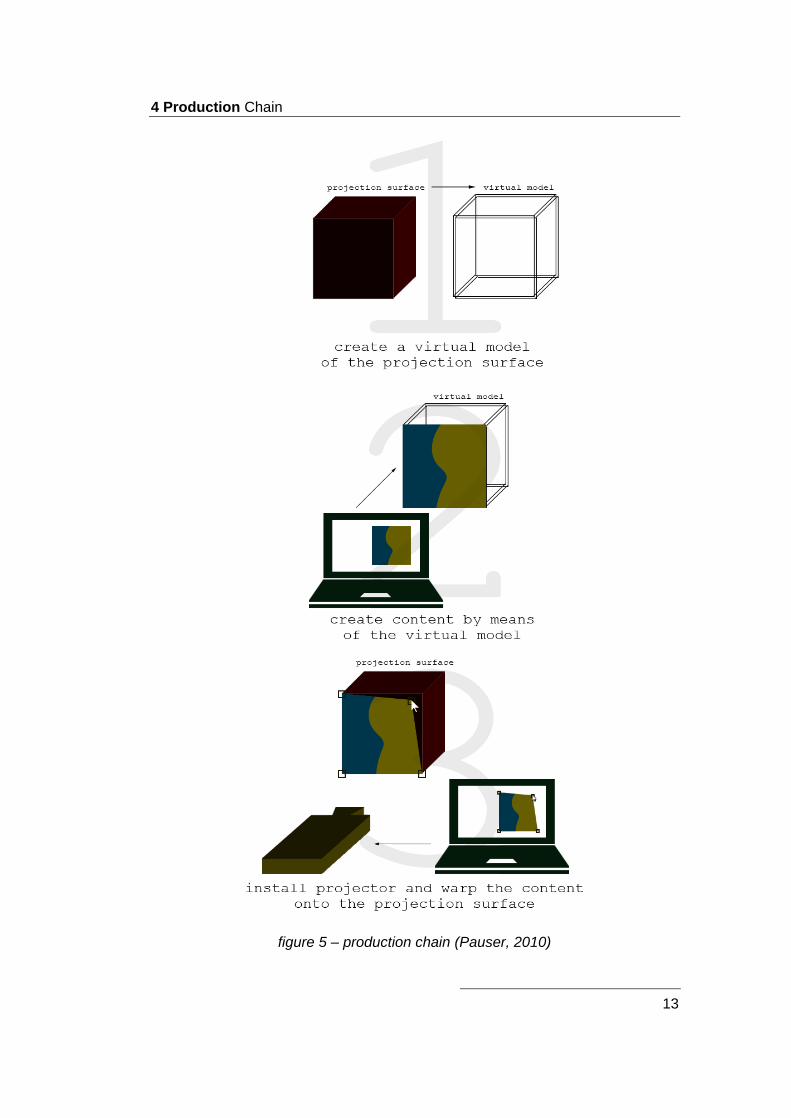
separated into three big steps as shown in figure 5 (Pauser, 2010, pp. 21-22).
The first step is the creation of a virtual model of the projection surface. The goal
is to create a virtual model, which has the exact geometry as the projection
surface. The more exact the model the better the result of the work. In the
simplest case, the model can be created from a picture with high resolution, or it
can be created with infrared sensors. In section 3.2.1 the different methods to
create such a model are listed and described. This step is necessary because
the artist, who creates the content for the PM needs something to work on as
described in the next step.
4 Production Chain
13
figure 5 – production chain (Pauser, 2010)

4 Production Chain
14
If the creation of the virtual model was successful, you can start creating the
content for the PM. The quality of the result benefits, if the artist works close
together with the model to get a good feeling what the projection surface looks
like. This means for example to separate layers like pillars and windows in a
façade projection from each other to merge the real and the virtual world
together. To create such content software like “Adobe After Effects”5 or
“Autodesk Maya” can be used. If you know the approximate position of the
projector in relation to the projection surface, you can create a virtual camera in
the composition and render the scene with a black background through this
camera to compensate first distortions. With the finalized render you can move to
the next step.
The aim of the third step is to install the projector and warp the content onto the
projection surface to compensate the position offset. For this task there is a lot of
different mapping software available. Software like “MXWendler” and
“Resolume”6 allow manually warping with different elements. This means on the
computer are different points visible, which can be repositioned on the surface to
warp it. Other software like “TouchDesigner” allows the import of the virtual
model and it calculates the position offset. The user just has to specify six points
on the projection surface.
Chapter 5, 6 and 7 analyze the work of three different, professional projects. In
addition, the software of one of these three steps and the projector they used are
described. In chapter Fehler! Verweisquelle konnte nicht gefunden werden. a
project goal is defined, different software is analyzed selected and is tested
together to evaluate the effectiveness of the setup.
5 http://www.adobe.com/at/products/aftereffects.html
6 https://resolume.com/

5 Box – Bot & Dolly
15
5 Box – Bot & Dolly
The experimental project “Box” by Bot & Dolly uses industrial robots, an actor,
illusion techniques and PM to create an astonishing performance, which was
captured in-camera. All effects of the five minutes video are created by the
complex installation without adding effects in the postproduction. The design of
the whole video is kept simple but it is all the more impressing. The design
concept of “Box” is based on five principles of illusion: transformation, levitation,
intersection, teleportation and escape. Each principle is built upon the previous
one (Munkowitz, 2013).
The performance takes place in Bot & Dolly’s hall in San Francisco, California.
Three industrial robots are used. Two of them are holding and controlling 4’ x 8’
white canvases, which function as projector screens. One of them is static; the
other one is mounted on a dolly system to cover a bigger range. The third robot is
responsible for the camera movement and takes care of the “viewer’s” right
position, to enable the illusions. Behind the canvases background lighting is
installed to expand the perceived projection area. In figure 6 you can see the
performance during the intersection part (Munkowitz, 2013).
figure 6 – Box (Box, 2013)
5 Box – Bot & Dolly
16
All illusions of the performance work because of the interaction between camera,
canvases and projected images. So the crucial point for working illusions is the
common coordinate system of the components. The projected images are
created in “Autodesk Maya”. The canvases and the camera are also controllable
through the robot software in the 3D scene. To synchronize all different 3D
scenes, Bot & Dolly developed their own software, called “BD Move”. In this way
a preprogrammed performance was created, which looks each take the same, so
that the actor has enough freedom to interact with the system to get the best out
of it (Cone, 2013).
To create the perception of the viewer more credible, the camera movements of
the robot have been humanized. A camera operator filmed the whole
performance with a shoulder rig. The movements of the shoulder rig have been
tracked and this motion path has been applied to the camera robot (The Creators
Project, 2013).
5.1 Autodesk Maya
As mentioned in chapter 5, most of the PM content was created in “Autodesk
Maya” (AM). AM is a 3D computer graphic software where the focus is on
animation, modelling, simulation and rendering. In the film and TV industry AM is
leading software for creating graphics and animations. It is designed for non-real-
time utilization. The user can operate in a three-dimensional grid to model
objects, animate them and the virtual camera and render the scene with different
materials and lights into motion pictures. “Autodesk Maya” is free for non-
commercial usage. The full version costs 200 euros per month (Autodesk, 2015).
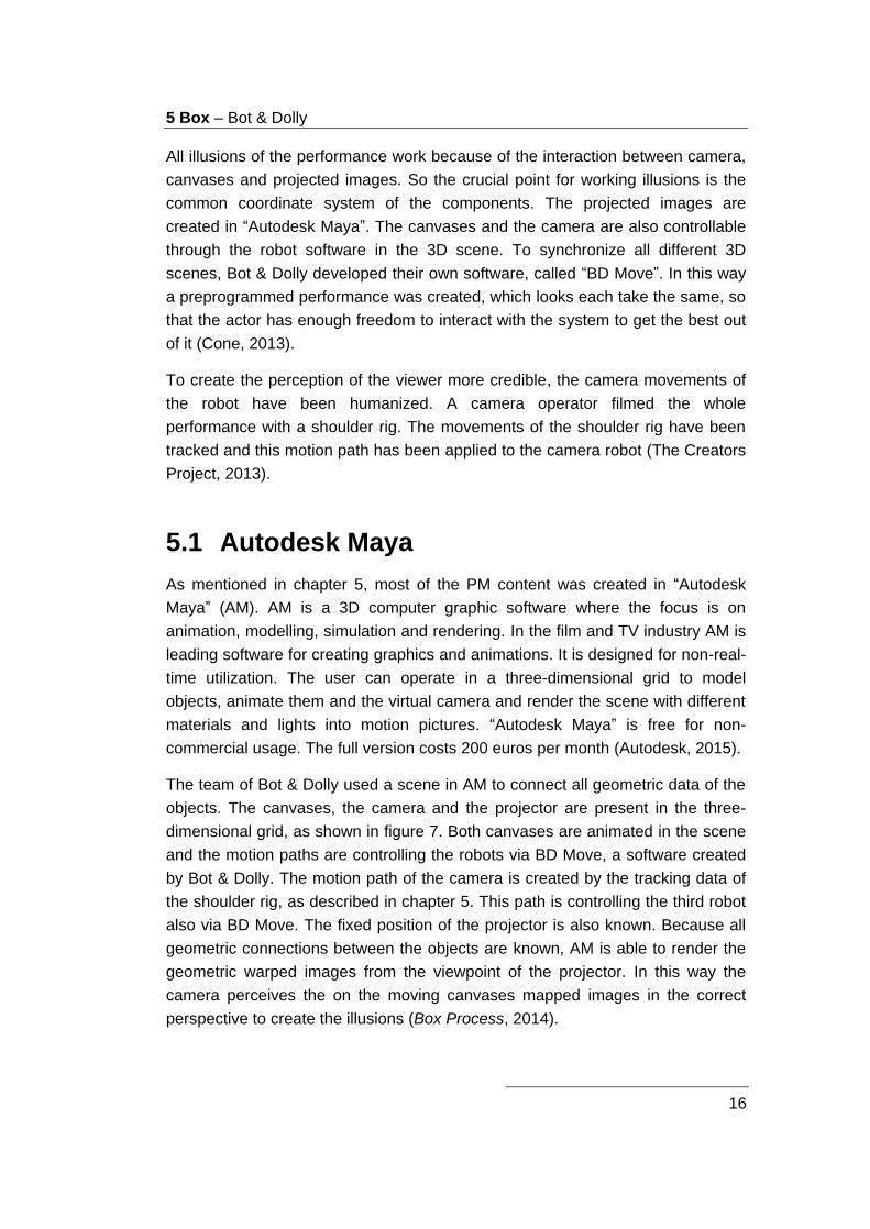
The team of Bot & Dolly used a scene in AM to connect all geometric data of the
objects. The canvases, the camera and the projector are present in the three-
dimensional grid, as shown in figure 7. Both canvases are animated in the scene
and the motion paths are controlling the robots via BD Move, a software created
by Bot & Dolly. The motion path of the camera is created by the tracking data of
the shoulder rig, as described in chapter 5. This path is controlling the third robot
also via BD Move. The fixed position of the projector is also known. Because all
geometric connections between the objects are known, AM is able to render the
geometric warped images from the viewpoint of the projector. In this way the
camera perceives the on the moving canvases mapped images in the correct
perspective to create the illusions (Box Process, 2014).

5 Box – Bot & Dolly
17
figure 7 – Autodesk Maya scene box (Box Process, 2014)
5.2 Christie DLP 4K Projector
Bot & Dolly used a Christie DLP 4K projector for their performance “Box”. For the
comparison with other projectors the Christie D4K3560 is assumed (Box
Process, 2014). This 3-chip-DLP projector has a native resolution of 4096x2160
pixels and provides a contrast of 2.000:1. With the 6.000 kilowatt lamp a
luminous power of 35.000 lumens in the center is generated (Christie Digital
Systems USA, 2015). The projector’s weight is about 114 kg and the price is
around 161.000 USD (Linda, 2013).
6 555 KUBIK – Urbanscreen
18
6 555 KUBIK – Urbanscreen
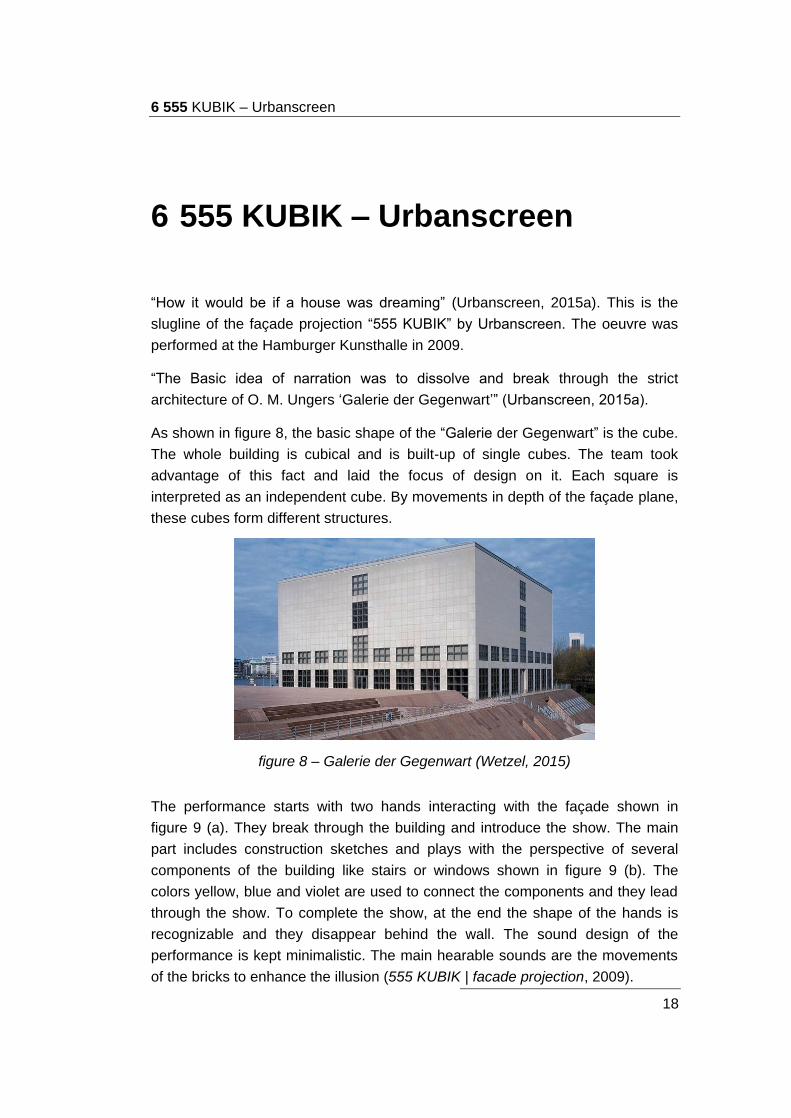
“How it would be if a house was dreaming” (Urbanscreen, 2015a). This is the
slugline of the façade projection “555 KUBIK” by Urbanscreen. The oeuvre was
performed at the Hamburger Kunsthalle in 2009.
“The Basic idea of narration was to dissolve and break through the strict
architecture of O. M. Ungers ‘Galerie der Gegenwart’” (Urbanscreen, 2015a).
As shown in figure 8, the basic shape of the “Galerie der Gegenwart” is the cube.
The whole building is cubical and is built-up of single cubes. The team took
advantage of this fact and laid the focus of design on it. Each square is
interpreted as an independent cube. By movements in depth of the façade plane,
these cubes form different structures.
figure 8 – Galerie der Gegenwart (Wetzel, 2015)
The performance starts with two hands interacting with the façade shown in
figure 9 (a). They break through the building and introduce the show. The main
part includes construction sketches and plays with the perspective of several
components of the building like stairs or windows shown in figure 9 (b). The
colors yellow, blue and violet are used to connect the components and they lead
through the show. To complete the show, at the end the shape of the hands is
recognizable and they disappear behind the wall. The sound design of the
performance is kept minimalistic. The main hearable sounds are the movements
of the bricks to enhance the illusion (555 KUBIK | facade projection, 2009).

6 555 KUBIK – Urbanscreen
19
figure 9 – 555 KUBIK (555 KUBIK | facade projection, 2009)
To make the movements of the bricks visible, a virtual light source was added to
the scene. It was positioned near the plane of the wall, to create long shadows.
The combination of shadows, sound effects and the real building creates a
credible illusion (555 KUBIK | facade projection, 2009).
As mentioned in (Böhm, 2011), four Sanyo XT35 projectors have been used for
the project “555 KUBIK”. To provide four projectors with synchronized content, a
main controller is needed. For “555 KUBIK” Urbanscreen worked with the
“FXServer” from “MXWendler”. In section 6.1 this device and the software are
described more detailed.
6.1 MXWendler
“MXWendler” is a company located in Germany. They develop software and
hardware for PMs and lightings in the field of theaters, events and installations.
Their software is called “Stage Designer” and it is optimized for their “FXServer”
(Hendrik, 2014).
“Stage Designer” is a real time video software and it can work with a lot of
different industrial standards. One of these standards is “Digital Multiplex” (DMX).
This digital protocol can be used for choosing media files or for remote keystone
control. Another compatible standard is “Open Sound Control” (OSC). The
“FXServer” utilizes OSC to communicate program flows to other systems or for
the synchronization with other “FXServers”, if more are required. It is also
possible to integrate devices with “Musical Instrument Digital Interface” (MIDI) to
control different properties, for example the opacity of a layer (Hendrik, 2014).
The simplest workflow for “MXWendler Stage Designer” is to import different
media, like images, video or audio, create a playlist out of them and warp the
output image to the shape of the object. The software is available in three
different price packages. The cheapest one costs about 190 euros and the pro,
6 555 KUBIK – Urbanscreen
20
the most expensive version, costs about 1.200 euros. Both versions are the
same but you have to buy the pro version if your venture has revenues higher
than 25.000 euros. The third version costs about 600 euros and is a downgraded
pro-version without playlists (device+context, 2015b).
“MXWendler” offers also a hardware solution for such projects. Their customized
“FXServer” is built in a 19 inches rack case and its components are optimized for
“Stage Designer”. The output reaches from two to six on VGA, DVI, HDMI and
SDI and the pricing starts at 10.000 euros (device+context, 2015a).
6.2 Sanyo XT35
As mentioned in chapter 6, Urbanscreen projected their “555 KUBIK” graphics
with four Sanyo XT35 projectors. To generate higher luminance two projectors
deliver the same image and are overlaid to each other. To cover the whole
façade two of this projector pairs are positioned next to each other (Böhm, 2011).
This 3-LCD projector creates 5.000 ANSI-lumen with a 330 watt projection lamp
and delivers a contrast of 1.000:1. With the Sanyo XT35 it is possible to project
images with 76.2 cm to 762 cm in the diagonal and it has a native XGA resolution
(1024x768 pixels) with an aspect of 4:3. If the projector is mounted angularly to
the plain of the object, it provides a vertical digital keystone correction of
plus/minus 40 degrees. The user can supply the Sanyo XT35 with images via
DVI-D. Without lens it has a weight of about 8 kg and it costs around 7.000 USD
(Projector Central, 2015).

7 Wooden Toy – Leviathan
21
7 Wooden Toy – Leviathan
In June 2011 Amon Tobin, a Brazilian musician and DJ, started his tour called
“ISAM” (Rousset, 2011). The show consists of live music and visuals. He and the
team of V Squared Labs developed a huge stage set. A lot of cubes form an
astonishing construction, which serves as a projection screen. In the center of
this construction Amon Tobin is placed, to provide this complex with energy. PM
is used to colorize the whole cube construction. The content of the PM was
generated by different design teams. The following part is about the work
“Wooden Toy” created by Leviathan (V Squared Labs, 2013).
“Wooden Toy – Hyperspace Steam Dream”, changes the construction of cubes
into a big system of wooden boxes. Some of them open from time to time and
enable the view inside. In this huge system strange machines and other moving
parts are working surrounded by steam. In this way, in combination with music, a
mysterious world in the wooden boxes is created as you can see in figure 10
(Leviathan, 2012).
figure 10 – Wooden Toy (Leviathan, 2012)
They attached great importance to work with analog materials in the projection
production process to create a certain analog feeling after joining the PMs with
the digital, electronic music. The design company Leviathan worked together with
the non-profit performance company Red Moon to create puppets and other
small machines, as shown in figure 11. These impressing objects combined with

7 Wooden Toy – Leviathan
22
steam, fire, motion and green screen were filmed and composited into the design
of the PMs (Leviathan, 2012).
figure 11 – puppets (Leviathan, 2012)
7.1 TouchDesigner
For the controlling of “ISAM’s” PMs V Squared Labs uses “TouchDesigner”,
which was developed by the Canadian company Derivative. It is a visual
development platform and it is specialized for real time projects. This tool can be
used for creating interactive media systems, PMs, live music visuals or just for
rapid-prototyping (Derivative, 2015a).
The idea of this visual development platform is to create different operators and
to connect them to each other. Each operator can have inputs and outputs and
changes the signal in a certain logical way. These in- and outputs are connected
through wires. The combinations of these operators form the so called network
(Lechner, 2014).
The software is able to handle with a lot of standards and enables in this way a
lot of possibilities. Audio and video data can be used as input source. Also input
data from different controllers can function as a source. “TouchDesigner” is able
to communicate through the internet with databases to exchange information. By
the use of DMX the software can control different lighting systems. Through
intelligent interconnection of these and many other elements, it is possible to
customize the logic system in any imaginable way (Derivative, 2015b).
7 Wooden Toy – Leviathan
23
An important tool for PMs is the feature called “CamSchnappr”. It works in
“TouchDesigner” and it can be used for aligning the projector’s output to the real
world geometry. The software knows the geometric data in form of the virtual
object. By aligning six or more points to the real world geometry, “CamSchnappr”
is able to warp the projector’s output to the real world geometry (Derivative,
2015b).
“TouchDesigner” is free for non-commercial use. This version includes only the
basic operators, a limited resolution of 1280x1280 and a DMX limitation of 32
channels. The versions with charge are divided into three price categories. The
educational version costs 300 USD, the commercial version 600 USD and the
pro version 2.200 USD. The first two versions are a downgraded pro version. If
“TouchDesigner” is used for paid work, the commercial or the pro version is
required (Derivative, 2015c).
7.2 Barco FLM HD20
Because for faster calibration, V Squared Labs used only one Barco FLM HD20
for the projection of “ISAM”. Another one served as a substitute (Barco, 2012).
It is important to have enough luminance, using just one projector. The Barco
FLM HD20 is a 3-chip-DLP projector and delivers 19.000 ANSI-lumen. The
projector has a Full-HD resolution of 1920x1080 pixels with an aspect of 16:9. A
3 kilowatt xenon lamp provides a contrast of 2.700:1. The Barco FLM HD20
weights 99 kg and costs about 70.000 USD (Barco, 2015).

8 Test Project “BREAKfast”
24
8 Test Project “BREAKfast”
In chapter 5, 6 and 7 three different computer programs and three different
projectors for projects in the field of PM were presented. Section 8.1 tries to
compare these tools to each other, evaluates their effectiveness for this project
and determines the setup. Section 8.2 documents the progress of the project and
section 8.3 reflects the work and lists the advantages and disadvantages of each
used tool to evaluate the effectiveness of the setup.
Project goal and general conditions:
For the whole projection one projector is used. To provide the projector with
warped images a computer with “Windows 7” is utilized. Because the projection
surface should consist of different shaped elements, a breakfast table consisting
of a plate, spoon, fork, cup and so forth was selected. Each one of these
elements should be masked to play an own role in the projection. To increase the
impression of the projection, it is supported by sound. Therefore, the used
software should also support sound. The duration for the show should be
between one and two minutes. The goal is to create a believable and stunning
performance. The tools should be selected on their suitability for the required
task and should move the project forward as fast as possible.
8.1 Tool Selection
The 3D computer graphic software “Autodesk Maya” is normally aimed at the film
and TV industry. Because it is developed for the non-real-time utilization, it is not
used to play back the footage for the PM, but it is used to create the content for
the PM. With the help of this tool, through modeling, animation and rendering, it
is possible to create photorealistic images. Because of the software’s enormous
force, it is often used in PM projects. But this force brings along a complex
usability and it has a long learning curve. Another disadvantage of “Autodesk
Maya” is the insufficient robustness. So it is always good to have enough
backups. If the geometric data of the projector and the object is known, the
software is able to render the correct geometric warped output for the projector.
8 Test Project “BREAKfast”
25
The software is free for students and for non-commercial usage, so that they can
learn to handle it.
In contrast, the focus of “MXWendler Stage Designer” is on real time utilization
for artists, VJs, theatres and performances. In the user interface preload different
media serves as source material. Effects like position, scale, transparency and
rotation can be applied to the source and it can be triggered with the keyboard.
The user interface playlist enables the possibility to create a program flow for
shows. For live sets the user interface live editor is used. It provides a spectrum
analyzer, with which you can control the amount of an effect depending on the
amount of an explicit frequency. The software’s keystone correction allows the
geometric warping on objects. With “MXWendler Stage Designer” it is possible to
supply two projectors at the same time. For up to six projectors, the “FXServer” is
required. The panorama wizard facilitates multifocal projection, by setting the
number of projectors, the soft edge and the amount of overlapping. Compared to
“Autodesk Maya” the “MXWendler Stage Designer” is easy to operate and you
can achieve good results much faster.
The most versatile tool of these three is “TouchDesigner” from Derivative. This
visual development platform provides the opportunity to create interactive media
systems and can be used for rapid-prototyping. The interconnections of different
operators through wires form a logic network. Especially the feature
“CamSchnappr” makes “TouchDesigner” a perfect tool for PMs. Through the
integration of a variety of sensors, protocols, controllers and data, a wide range
of projects can be realized. “TouchDesigner” is free for non-commercial usage.
To make the tool selection clearly, this paragraph refers to the production chain
in chapter 4. The tools are selected for each of the different steps, “create a
virtual model of the projection surface”, “create content by means of the virtual
model” and “install projector and warp the content onto the projection surface” on
the basis of their suitability.
In “BREAKfast” the projector is mounted above the plane of the breakfast table,
so the plane is, except of the dishes’ height, two-dimensional. Because of this
fact, a creation of a virtual three-dimensional model is needless. Therefore an
image from the projectors’ position is used as a reference image and a virtual
model.
After capturing the virtual model the content will be created in “Adobe After
Effects”. This software delivers a quite good result in a short time. Furthermore, it
works close together with other Adobe products like “Adobe Photoshop”. Another
8 Test Project “BREAKfast”
26
option would be “Autodesk Maya”, but it would need a lot more effort to get the
same result for this project.
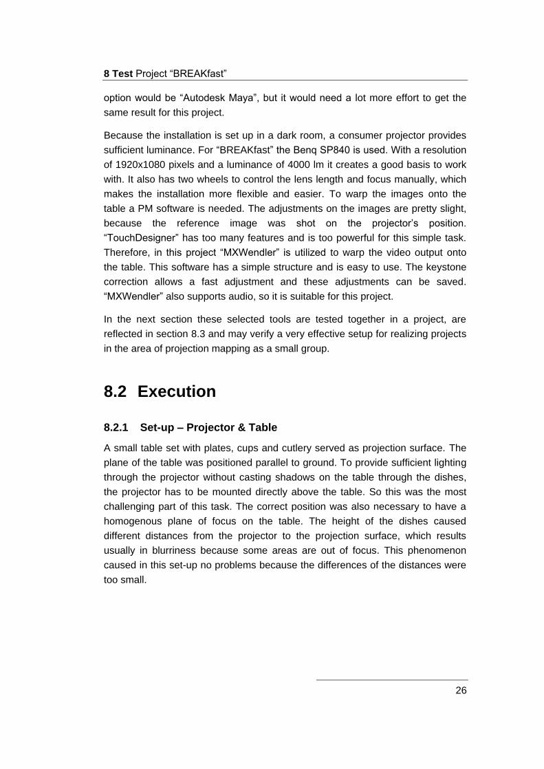
Because the installation is set up in a dark room, a consumer projector provides
sufficient luminance. For “BREAKfast” the Benq SP840 is used. With a resolution
of 1920x1080 pixels and a luminance of 4000 lm it creates a good basis to work
with. It also has two wheels to control the lens length and focus manually, which
makes the installation more flexible and easier. To warp the images onto the
table a PM software is needed. The adjustments on the images are pretty slight,
because the reference image was shot on the projector’s position.
“TouchDesigner” has too many features and is too powerful for this simple task.
Therefore, in this project “MXWendler” is utilized to warp the video output onto
the table. This software has a simple structure and is easy to use. The keystone
correction allows a fast adjustment and these adjustments can be saved.
“MXWendler” also supports audio, so it is suitable for this project.
In the next section these selected tools are tested together in a project, are
reflected in section 8.3 and may verify a very effective setup for realizing projects
in the area of projection mapping as a small group.
8.2 Execution
8.2.1 Set-up – Projector & Table
A small table set with plates, cups and cutlery served as projection surface. The
plane of the table was positioned parallel to ground. To provide sufficient lighting
through the projector without casting shadows on the table through the dishes,
the projector has to be mounted directly above the table. So this was the most
challenging part of this task. The correct position was also necessary to have a
homogenous plane of focus on the table. The height of the dishes caused
different distances from the projector to the projection surface, which results
usually in blurriness because some areas are out of focus. This phenomenon
caused in this set-up no problems because the differences of the distances were
too small.

8 Test Project “BREAKfast”
27
figure 12 – projector mount
To mount a projector in such an unusual way the “OMB Monoprojector” ceiling
mount was bolted onto a wooden cube. This cube was mounted through screw
clamps onto the wardrobe as shown in figure 12.
8.2.2 Shoot Footage
To create photorealistic content the majority was shot beforehand. It was
important to keep the angle between the camera and the object the same as the
angle between the projector and the object, this means shooting straight down on
the top of the objects. Soft light was used to illuminate the scene to avoid strong
shadows, which could limit the creative possibilities during the compositing. The
theme of this project is breakfast, so the goal of the shooting was to capture as
many meals as possible. The filmed footage gave a good basis to compose with,
as shown in figure 13.

8 Test Project “BREAKfast”
28
figure 13 – shot footage
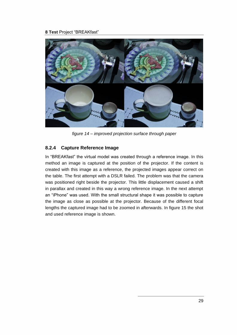
8.2.3 Test Credibility of Footage on Projection Surface
After shooting the footage it was projected onto the table and the dishes to check
the credibility of it. Some parts needed improvements. The plates were too
reflective so that the projected food was blurry. Gray paper circles solved the
problem. They were laid in the middle of the plates and the projected images
appeared sharper. A similar problem occurred at the cup and the bowl. The
projected images immersed into them and it felt unnatural and not credible. Here
the paper solved again the problem. A circle was laid on top of the cup, the bowl
and the eggcup and lifted the projection surface. In this way the projected images
got credible. The improvements through the paper are shown in figure 14.
8 Test Project “BREAKfast”
29
figure 14 – improved projection surface through paper
8.2.4 Capture Reference Image
In “BREAKfast” the virtual model was created through a reference image. In this
method an image is captured at the position of the projector. If the content is
created with this image as a reference, the projected images appear correct on
the table. The first attempt with a DSLR failed. The problem was that the camera
was positioned right beside the projector. This little displacement caused a shift
in parallax and created in this way a wrong reference image. In the next attempt
an “iPhone” was used. With the small structural shape it was possible to capture
the image as close as possible at the projector. Because of the different focal
lengths the captured image had to be zoomed in afterwards. In figure 15 the shot
and used reference image is shown.

8 Test Project “BREAKfast”
30
figure 15 – reference image
8.2.5 Create Keystone Correction
The captured reference image got adjusted in color and luminance to create
sharp contrast at the edges of the dishes to make the creation of the alpha
masks easier. The image was also scaled to the approximate size of the
projector frame. This corrected image was imported in “MXWendler” and was
played back. While projecting the reference image onto the same table, the
keystone correction of “MXWendler” was utilized to warp the image into the real
object as shown in figure 16.
figure 16 – keystone correction in “MXWendler”

8 Test Project “BREAKfast”
31
Because the picture was captured almost at the same position as the projector,
these warp adjustments are pretty slight. The software allows saving such a
keystone correction. In this way the content can be produced with the reference
image and by using the saved keystone correction it is ensured that the final
video is correctly warped onto the dishes.
8.2.6 Create Alpha Masks
Alpha masks were made, to speed up the creation of the content. Because every
single object on the table should play an own role in the project, each of those
got an own mask. They were created in “Adobe Photoshop” by drawing over the
reference image as shown in figure 17.
figure 17 – alpha masks
While drawing these masks, they were imported into “MXWendler” and were
projected with the saved keystone correction onto the table to double check their
precision.
8.2.7 Create Content
The one and a half minutes presentation starts with realistic food and drinks on
the plates and cups. After the break it turns into a surreal world. Audio was
designed beforehand and video was adapted to it. The filmed footage and
footage from the World Wide Web was composed together in “Adobe After
Effects” into a presentation as shown in figure 18.

8 Test Project “BREAKfast”
32
figure 18 – content creation in “Adobe After Effects”
The final piece of work is online and available under following link:
https://youtu.be/ktnT7EhAP_4
8.3 Reflection
In section 8.2 the work and the used tools of “BREAKfast” were presented. This
section reflects the experiences and tries to evaluate the effectiveness of the
tools for such projects to enable a quick start for beginners in this field.
A big advantage was that the set-up of the projector and the table was present
during the whole time of content creation. This allows tests on the real installation
all the time. A requirement therefore is a robust set-up. This means the position
of the projector and the table has to be totally fixed for the whole time. The
“Monoprojector” ceiling mount from “OMB” isn’t completely robust. It allows 360
degrees rotation and 30 degrees up and down tilt and is therefore very flexible.
But the whole mount is a bit shaky with a projector on top, which could cause
problems during the development and presentation.
To shoot own footage for the PM project could save a lot of time. For this project
it was possible to shoot many different objects with the same set-up. The whole
process of eating a meal was filmed in one clip. The parts where the food got
reduced were cut out and played back like a stop motion film. Another option
would be to shoot it just with still frames, which would have the same effect, but it
would be possible to record it in a RAW-file. An alternative option would be to

8 Test Project “BREAKfast”
33
include the action of the eating and serving hands and integrate them into the
compositing.
The method with the reference image at the position of the projector worked
pretty well. The final result was good. The only improvement would be to invest
more time in capturing this image. Because there was not enough light, the
quality of the image is low. This resulted in a time-consuming creation of the
alpha masks. It wasn’t possible to use the magic wand tool in “Adobe Photoshop”
so the masks had to be drawn manually. In future projects it would be better to
spend more time in lighting the object before shooting the reference image than
in drawing masks.
The experience with “Adobe After Effects” in this project was great. It was
possible to realize ideas in a short amount of time. Parts of the video or just
frames were rendered and imported into “MXWendler” to check the feeling of the
images on the real object.
“MXWendler” was utilized to play back the final video and audio and to warp the
image onto the table. These tasks were done quickly. The user interface of the
keystone correction allows fast warping. The grid can be manipulated manually
with the cursor for big adjustments and with the arrows of the keyboard for fine
adjustments. It was the right decision to use this software instead of
“TouchDesigner”, because these easy tasks were fulfilled with a great result in a
short time.
Since the presentation took place in a darkened room, a variety of consumer
projectors would make it possible to illuminate the object. The Benq SP840 did a
great job and supported the project with the resolution of 1920x1080 progressive
and a luminance of 4000 lm. Other benefits are the adjustment wheels for focal
length and focus, which make it really flexible.

9 Conclusion
34
9 Conclusion
At the beginning of this research paper the idea of PM in general was defined.
Additionally, the necessary techniques were introduced, which are important for a
credible PM. The need of geometric warping was explained and their different
types were listed. A good example of radiometric compensation was shown and
illustrated. If it is essential to use multiple projectors, a scientific experiment
explained its process.
Furthermore, to receive an impression about the possibilities of PM, three actual
projects were analyzed. “Box” demonstrated the possibility to connect PM with
other technical equipment. “555 KUBIK” served as a good example for façade
projection and “Wooden Toy” showed the connection between analog and digital
work.
Moreover, with the gained knowledge of the professional projects an own project
goal was defined. For each step of the production chain the most appropriate
tools were selected and tested together in this project. The effectiveness of these
used tools was evaluated, reflected and presented to form a good basis for
beginners to enable them a quick start in their own projects.
Following researches in this field could concentrate on specific, detailed
questions and could go deeper into the topic. In addition, it would be also
interesting to test different tools in projects where the position of the audience is
known and three-dimensional effects could be included. Another suggestion is to
test and improve the workflow of capturing and importing the geometric data of
the used object into any software.
35
References
555 KUBIK | facade projection. (2009). Retrieved from https://vimeo.com/5595869 Autodesk. (2015). Software für 3D-Animation und Modellierung | Maya | Autodesk. Retrieved June 27, 2015, from http://www.autodesk.de/products/maya/overview Barco. (2012). Amon Tobin’s ISAM Live tour features Barco projection for 3D musical art installation created by V Squared Labs, blasthaus and Vita Motus Design Studio Rancho Cordova. Retrieved June 15, 2015, from http://www.barco.com/de/News/Press-releases/Amon-Tobins-ISAM-Live-tour-features-Barco-projection-for-3D-musical-art-installation-created-by-V-Sq.aspx Barco. (2015). 20.000 Lumen, 1080p HD, 3-Chip-DLP-Projektor - FLM-HD20 | Barco. Retrieved June 28, 2015, from http://www.barco.com/de/Produkte-und-L%C3%B6sungen/Projektoren/Projektoren-f%C3%BCr-Gro%C3%9Fveranstaltungen/20000-Lumen-1080p-HD-3-Chip-DLP-Projektor.aspx#!specs Bimber, O., & Emmerling, A. (2006). Multifocal projection: a multiprojector technique for increasing focal depth. IEEE Transactions on Visualization and Computer Graphics, 12(4), 658–667. http://doi.org/10.1109/TVCG.2006.75 Böhm, G. (2011). 3D Videomapping - die Kunst der Architektursimulation. FH Hagenberg, Hagenberg, Austria. Box. (2013). Retrieved from https://vimeo.com/75260457 Box Process. (2014). Retrieved from https://vimeo.com/102776011 Budhiraja, P. (2015, June 4). Blizzard uses Projection Mapping to launch new game! - Projection Mapping Central. Retrieved June 5, 2015, from http://projection-mapping.org/blizzard-uses-projection-mapping-to-launch-new-game/ Christie Digital Systems USA. (2015). Christie D4K3560 high frame rate 3-chip DLP 4K Projector | Christie – Visual Solutions. Retrieved June 28, 2015, from http://www.christiedigital.com/en-us/business/products/projectors/3-chip-dlp/pages/christie-d4k3560-3-chip-dlp-4k-projector.aspx Cone, J. (2013, October 1). Bot & Dolly: “Box” Interview and Behind the Scenes. Retrieved May 11, 2015, from http://motionographer.com/2013/10/01/bot-dolly-box-interview-and-behind-the-scenes/ CVPR 2004 Video. (2010). Retrieved from http://www.cs.columbia.edu/CAVE/projects/pr_any/mpegs/controlAppearance.mpg

36
Derivative. (2015a). Derivative TouchDesigner. Retrieved June 28, 2015, from https://www.derivative.ca/ Derivative. (2015b). Derivative TouchDesigner 088. Retrieved June 28, 2015, from https://www.derivative.ca/088/Features/ Derivative. (2015c). Licensing - TouchDesigner 088 Wiki. Retrieved June 28, 2015, from http://www.derivative.ca/wiki088/index.php?title=Licensing device+context. (2015a). Products - Mediaserver - MXWendler, Mediaserver, VJ Software, Videomapping, LED lighting- MX Wendler. Retrieved June 27, 2015, from http://www.mxwendler.net/products/mediaserver.html device+context. (2015b). Products - Software - MXWendler, Mediaserver, VJ Software, Videomapping, LED lighting- MX Wendler. Retrieved June 27, 2015, from http://www.mxwendler.net/products/software.html haunted mansion ride. (2013). Retrieved from https://www.youtube.com/watch?v=Ft9fxLAhZBE Hendrik, W. (2014). Benutzerhandbuch MXWENDLER 5.0. Hendrik Wendler. Retrieved from http://www.mxwendler.net/fileadmin/user_upload/downloads/manual_mxw_5.0_de.pdf Hronek, J., & Dieni, G. (2011). HOW TO. Retrieved from http://videomapping.org/?page_id=42 Jones, B. (2012a, November 15). What is projection mapping? Retrieved March 25, 2015, from http://projection-mapping.org/whatis/ Jones, B. (2012b, December 20). The Illustrated History of Projection Mapping - Projection Mapping Central. Retrieved May 25, 2015, from http://projection-mapping.org/the-history-of-projection-mapping/ Jones, B. (2015a, January 19). So you think Disney invented the projected wedding cake? - Projection Mapping Central. Retrieved June 5, 2015, from http://projection-mapping.org/disneys-projection-mapped-wedding-cake/ Jones, B. (2015b, May 30). Amadeus - Interactive Projection Mapped Piano - Projection Mapping Central. Retrieved June 7, 2015, from http://projection-mapping.org/amadeus-interactive-projection-mapped-piano/ Lechner, P. (2014). Multimedia Programming Using Max/MSP and TouchDesigner. Packt Publishing Ltd. Leviathan. (2012). Wooden Toy. Retrieved June 15, 2015, from http://www.lvthn.com/work/wooden-toy/ Linda. (2013, April 25). Christie Debuts 4K Resolution, 60 Hz Projector | PMA Research. Retrieved from http://www.pmaresearch.com/pma-blogs/christie-debutes-4k-resolution-60-hz-projector/

37
Multi-Focal Projection. (2008). Retrieved from https://www.youtube.com/watch?v=C_jtOy6wKRs Munkowitz, B. G. (2013, September). BOX DEMO - .work | GMUNK. Retrieved May 11, 2015, from http://work.gmunk.com/BOX-DEMO Nayar, S. K., Peri, H., Grossberg, M. D., & Belhumeur, P. N. (2003). A projection system with radiometric compensation for screen imperfections. Occipital, Inc. (2015). The Structure Sensor - Developer Information - SDK. Retrieved May 26, 2015, from http://structure.io/developers Oliver, B., & Ramesh, R. (2005). Spatial Augmented Reality Merging Real and Virtual Worlds. A K Peters, Ltd. Pauser, V. (2010). Oberfläche als Gestaltungsmittel verwirklicht durch perspektivisch korrigierte Projektion auf dreidimensionale Objekte. FH Hagenberg, Hagenberg. Retrieved from http://theses.fh-hagenberg.at/thesis/Pauser10 Projector Central. (2015). Sanyo Projectors: Sanyo PLC-XT35 3 LCD projector. Retrieved June 15, 2015, from http://www.projectorcentral.com/Sanyo-PLC-XT35.htm Rousset, I. (2011, July 12). ON VISUALIZING AMON TOBIN’S ISAM with the V SQUARED TEAM. Retrieved May 14, 2015, from http://www.derivative.ca/Events/2011/AmonTobinVSquared/ The Creators Project. (2013, October 1). Behind The Scenes Of Box By Bot & Dolly. Retrieved May 11, 2015, from http://thecreatorsproject.vice.com/blog/exclusive-video-the-making-of-box Urbanscreen. (2015a). 555 KUBIK / Hamburg. Retrieved May 11, 2015, from http://www.urbanscreen.com/555-kubik/ Urbanscreen. (2015b). SEARCHLIGHT / Bremen. Retrieved June 7, 2015, from http://www.urbanscreen.com/searchlight/ V Squared Labs. (2013). Amon Tobin ISAM. Retrieved from http://vsquaredlabs.com/project/amon-tobin/ V Squared Labs. (2014). Skrillex: Mothership Tour. Retrieved from http://vsquaredlabs.com/project/skrillex/ Wetzel. (2015, June 10). 005_012_02_KunstinselHamburg_L.jpg (730×520). Retrieved June 10, 2015, from http://www.wetzelvonseht.com/uploads/tx_projekte/005_012_02_KunstinselHamburg_L.jpg

38
List of figures
figure 1 – the idea of projection mapping (Jones, 2012a) ..................................... 4
figure 2 - 5 singing busts (Jones, 2012b) .............................................................. 5
figure 3 – radiometric compensation (CVPR 2004 Video, 2010) ........................... 8
figure 4 – multifocal projection (Multi-Focal Projection, 2008) ............................... 9
figure 5 – production chain (Pauser, 2010) ......................................................... 13
figure 6 – Box (Box, 2013) ................................................................................... 15
figure 7 – Autodesk Maya scene box (Box Process, 2014) ................................. 17
figure 8 – Galerie der Gegenwart (Wetzel, 2015) ................................................ 18
figure 9 – 555 KUBIK (555 KUBIK | facade projection, 2009) ............................. 19
figure 10 – Wooden Toy (Leviathan, 2012) ......................................................... 21
figure 11 – puppets (Leviathan, 2012) ................................................................. 22
figure 12 – projector mount ................................................................................. 27
figure 13 – shot footage ....................................................................................... 28
figure 14 – improved projection surface through paper ....................................... 29
figure 15 – reference image ................................................................................ 30
figure 16 – keystone correction in “MXWendler” ................................................. 30
figure 17 – alpha masks ...................................................................................... 31
figure 18 – content creation in “Adobe After Effects” ........................................... 32