Embed Size (px)
Citation preview
Vol.:(0123456789)
https://doi.org/10.1007/s10443-021-09948-1
1 3
An Effective Method of Modeling the Deformation Behavior of Polymer Sandwich Structures with Adhesive Joints
László Takács1,2 · Ferenc Szabó1
Received: 3 January 2021 / Accepted: 22 July 2021 © The Author(s) 2021
AbstractPolymer sandwich structures have high bending stiffness and strength and also low weight. Therefore, they are widely used in the transportation industry. In the conceptual design phase, it is essential to have a method to model the mechanical behavior of the sandwich and its adhesive joints accurately in full-vehicle scale to investigate different structure partitioning strategies. In this paper, a novel approach using finite element modeling is introduced. The sandwich panels are modeled with layered shells and the joint lines with general stiffness matrices. Stiffness parameters of the face-sheets and the core material are obtained via mechanical tests. Stiffness parameters of the joints are determined by using the method of Design of Experiments, where detailed sub-models of the joints serve as a reference. These models are validated with experimental tests of glass-fiber reinforced vinyl ester matrix composite sandwich structure with a foam core. By using two joint designs and three reference geometries, it is shown that the method is suitable to describe the deformation behavior in a full-vehicle scale with sufficient accuracy.
Keywords Sandwich · Adhesive joint · Finite element method
1 Introduction
In the case of polymer composite structures, the most common joint technique is the adhe-sive joint [1]. The reliability of these joints is growing fast due to important technological developments regarding bonding technology and surface preparation of composites as well [2–5]. In the design phase, it is essential to model the mechanical behavior of the structures together with their joints accurately. In recent years extensive studies have been performed due to its industrial significance by using analytical or numerical calculations.
* László Takács [email protected]
Ferenc Szabó [email protected]
1 Department of Polymer Engineering, Faculty of Mechanical Engineering, Budapest University of Technology and Economics, 1111 Budapest, Hungary
2 eCon Engineering Kft, Budapest, Hungary
Published online: 17 August 2021
Applied Composite Materials (2021) 28:1959–1978
/
1 3
Manalo and Aravinthan [6] showed an analytical and experimental investigation of a glued sandwich material used in civil engineering applications. It consists of a glass fiber reinforced polymer skin and a high strength phenolic core material. An analytical method called Fiber Model Analysis (FMA) is adopted, which is widely used for the analysis of concrete beam structures. The analytical method takes into account the non-linear behavior of the core material in compression, the cracking of the core in tension, and the linear elas-tic behavior of the composite face-sheets. By considering these effects, the results showed a good agreement with experimental tests, so the method can be efficient when design-ing sandwich structures under flexural load. Navarro et al. [7] introduced a new analytical method to model indentation of foam-core sandwich beams caused by localized loadings. It assumes that the response of the foam-core in compression can be modeled as elastic-perfectly plastic. The analytical results were validated with Finite Element calculation and experimental tests as well. The deformation behavior, as well as the stress state can be efficiently modeled with this method, and accurate results can be given. Paczos et al. [8] pointed out the effect of material inhomogeneity on stiffness and strength in an analytical method. The authors tested short sandwich beams with a honeycomb type of core. The specimens were made with fused deposition modeling (FDM), an additive manufacturing technology, using polylactide acid (PLA) material. Stiffness properties were investigated with three-point bending, and deformation behavior was modeled analytically. Anish et al. [9] developed a 2D analytical tool to calculate the failure of laminated composite sandwich beams. Higher-order shear deformation theory was used, and the method was implemented in Fortran. The model is robust enough, and the results show good agreement with 3D models.
Analytical methods can give a less time-consuming solution or can be a good base for developing the more application-close finite element methods. Finite element models, on the other hand can provide a deeper understanding of the mechanical behavior of the struc-tures. The development and application of the numerical simulations are widespread in all industries.
Kpeky et al. [10] developed a new element type for finite element calculations for sand-wich beams with harmonic excitations or free vibration, which is a solid-shell finite ele-ment. The element was implemented in MatLab, and several numerical tests were carried out with various cantilever beam configurations. With the new element-type, the authors could overcome the limitations of sandwich structures like the high contrast of material properties or high geometric aspect ratios. Ferdous et al. [11] also investigated a so-called layered sandwich beam that consists of glass fiber reinforced polymer matrix skins and a phenolic core, and several layers of this type of sandwich beams are glued together with epoxy resin. The authors tested different layer configurations and different skin orienta-tions experimentally, and developed a finite element model also. Possibilities of stiffness and strength increase were shown while preventing wrinkling and buckling at the same time. Vidal et al. [12] developed a high-order beam element for finiteelement analysis to allow the user to model a laminated beam with a genericcross-section, thus reducing the computational cost. A so-called variable separation method was used, where the displace-ment field is approximated as a sum of separated functions of the cross-section coordinates and the axial coordinate. Results are shown with different sandwich beams comparing the modelwith a 3D-model of second-order solid elements. The accuracy of providing even 3D results is confirmed. A non-linear model was developed by Odessa et al. [13] for the simulation of the debonding process between the face-sheet and the core of a sandwich panel. The model uses extended high-order sandwich panel theory and cohesive interface modeling techniques [14]. Double cantilever beam (DCB) and cracked sandwich beam
1960 Applied Composite Materials (2021) 28:1959–1978
1 3
(CSB) specimens were used to investigate global modeI and mode II loadings. The model is validated with experimental results. Besides the stiffness and strength of sandwich struc-tures, theload-introduction with these materials is also a problem to solve. Assaad et al. [15] analyzed the behavior of non-structural sandwich panels against wind-load or seismic-load. Stiffness and strength of different material mixtures were tested experimentally, and differ-ent load-introduction designs were investigated to fix the panels to a load-bearing structure. Composite load-carrying boxes with different geometries and load conditions were ana-lyzedby Tang et al. [16] in the early design phase. They also used a commercial finite ele-ment software and evaluated static and buckling failure. These kinds of studies help engi-neers a lot during the design phase, but the accuracy canbe challenging when dealing with big-sized and complex-shaped structures.
In the automotive or in the autobus industry where the parts are geometrically complex, the design process is heading from integral to the so-called differential design when parti-tioning parts due to cost reasons [17]. Thus, the mechanical characterization of adhesive joints of polymer structures is also essential to investigate. Standard tests to characterize even the stiffness properties of adhesive bonds have several deficiencies. When testing lap joints, the specimens produce complex stress distributions, irregularities, or even singulari-ties. Dragoni and Brinson [18] investigated a method to determine the shear strength and shear modulus of an adhesive with the three-point bending of a single sandwich specimen, which consists of two flat plates and the adhesive between them. They developed an accu-rate model and validated it with finite element analysis. Optimization studies were per-formed to examine the possibilities of finding the proper material and sizes of the adher-ents of the specimen with different adhesives. The method can be effectively used when having an adhesive with linear deformation behavior. With a linear assumption, also Van Loock et al. [19] performed a fundamental research and showed comprehensive maps of regimes of failure mechanisms of adhesive joints as a function of elastic mismatch and non-linearity of cracked sandwich specimens where the loading is tension only. If the test of an adhesive with pure loading is to be done, a complex test-fixture (e.g., Arcan) is needed. Jiang et al. [20] developed a specific loading device to test the adhesive joint of a polymer sandwich panel to steel girders of a bridge. Six different loading angles can be applied, pure shear, pure tension, and four combined loadings, and the mechanical behav-ior of the joint can be investigated. The authors used linear elastic finite element calcula-tions as well to characterize the stress distribution in the adhesive. The results show that the joint has a higher load-bearing capacity at pure loading and lower at combined loading. A corrugated core sandwich panel is introduced by Yu et al. [21], in which the core panel is bonded with an adhesive joint to the face sheet. Elastic constants of the sandwich panel are derived considering the adhesive layer distortions, and a closed-form solution is given. The results are validated with a 3D finite element analysis. By Yu et al. [22], also the finite element method was used to predict the failure of adhesively bonded composites. Cen et al. [23] investigated different adhesive joint designs with polymer sandwich panels consist-ing of glass fiber reinforced polymer composite face-sheets and PVC foam as core mate-rial. Four-point bending tests and dynamic finite element simulations were performed. In the simulations, the 3D Hashin failure criterion was used, which could predict failure in a good agreement with the tests. The Hashin criterion was also used to evaluate the strength of composite materials by Li et al. [24]. An adhesively bonded T-joint with braided com-posites was analyzed with finite element simulations where cohesive elements were used to model the failure of the adhesive. Composite sandwich T-joints were also analyzed by Khosravani et al. [25]. The authors carried out different mechanical tests to investigate the effect of strain-rate on failure mode and fracture behavior of honeycomb sandwich
1961Applied Composite Materials (2021) 28:1959–1978
1 3
structures. Strain measurements with digital image correlation and results of numerical analysis performed with Abaqus software showed an excellent agreement. Adhesively bonded reinforcements of a ship deck made of polymer sandwich structure were investi-gated by Bella et al. [26]. They also carried out experimental tests and performed finite ele-ment simulations using solid- and shell elements. Different design variants were compared regarding stiffness and strength.
The mechanical behavior of the joints is influenced by the geometry, the material prop-erties, and loading conditions as well. The complexity of the joints is increasing, and the material non-linearity is also difficult to model in a mathematical formulation. Experimen-tal tests can often be time-consuming and costly; therefore, the importance of numerical simulation becomes higher. Several methods of finite element analysis of adhesive joints with composite adherents can be found in the literature, Budhe et al. [27] summarized them in a comprehensive review article.
A review of the literature shows that there are extensive studies to develop analyti-cal models and simulation methods to understand the mechanical behavior of sandwich structures and their adhesive joints. The analytical methods often work only with beam- or plate-like geometries with idealized boundary conditions. At the same time, the finite ele-ment models are often too detailed and can be effectively used only in specimen scale. In recent years the product development aims to maximize virtualization and minimize pro-totyping by using even more simulation techniques and even fewer physical prototypes, and so the design cost will decrease. Top manufacturers in the automotive industry target “zero-prototyping” where the role of simulation increases drastically. This indicates the need to develop a modeling method for sandwich panels and their adhesive joints to help the design process in the conceptual design phase, that can be effectively used in a full structure scale.
This paper aims to fill this gap and introduces a new finite element modeling method using layered shell elements with proper orthotropic stiffness constants for the sandwich panels and general stiffness matrices for the joints. The parameters of the stiffness matrices are carried out from specimen tests and a numerical method called design of experiments (DoE). The method is investigated with a polymer sandwich panel with different joint geometries. This new method allows us to test different partitioning strategies and joint designs fast and easily with adequate accuracy and can be an effective tool in a simulation-driven product development.
2 Materials and Experimental Tests
The material chosen to demonstrate the modeling method and to validate the finite element models is a glass fiber reinforced, vinyl ester matrix composite. This mate-rial is generally used in the transportation industry, e.g., buses or truck superstruc-tures. The fiber reinforcement is a multidirectional fabric with a stacking sequence of 0°/45°/90°/-45°. The commercial name of the product is quadraxial fabric. The specific weight is 1232 g/m2. The face-sheet of the tested sandwich structure has three layers of this fabric with the same orientation and with a symmetric lay-up. The thickness of the face-sheet is 2.5 mm. The quasi-isotropic lay-up is common in the industry, it is a safe solution if the structure is under multiaxial loading. In a vehicle body, the torsional load is the most typical one, and the layers with ± 45° ori-entation give proper resistance against it. The matrix material is a Distitron VE220
1962 Applied Composite Materials (2021) 28:1959–1978
1 3
vinyl ester. Vinyl ester is the cheaper but a little weaker alternative of epoxy, which is used mostly in transportation industry, e.g., composite autobus manufacturers use this material in Europe and North America. This material is to be used with resin-transfer molding or vacuum infusion technology. The specimens were manufactured with vacuum infusion technology, Butanox-M50 (methyl ethyl ketone peroxide, solu-tion in dimethyl phthalate) was used as an initiator and 0.2 wt% cobalt solution as an activator. The curing time was 24 h at room temperature and then 3 h at 100 °C according to the datasheet of the resin manufacturer.
The core material of the sandwich panel is Airex T90 polyethylene terephthalate (PET) foam. It is a closed-cell foam with a density of 110 kg/m3. The type of the foam is named FlexiCut. It has a thickness of 25 mm with 1.2 mm thick cutsevery 30 mm. Both sides have cuts, on one side, 85% of the thickness is cut; on the other side the 20% of the thickness. These cuts help the manufacturing, they transfer the resin, and this structure allows the full impregnability of the sandwich.
To characterize the mechanical properties of different joint designs, a two-component, high strength, high elongation methacrylate adhesive AcraLock SA 10 HV was used.
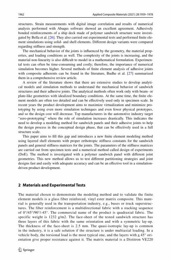
Two different joint geometries were investigated; they are shown in Fig. 1. On the left, the figure of the scarf-joint can be seen; on the right, there is the mortise-tenon joint.
To determine the stiffness parameters of the structure and to validate the deformation behavior of the finite element models, different mechanical tests were performed on a Zwick Z020 uniaxial testing machine on room temperature and with a relative humidity of 46 ± 2%. The Young’s moduli and Poisson-ratios of the composite face-sheets were carried out with a displacement controlled tensile test following EN ISO 527–4 standard with the Type 3 specimen. The test speed was 2 mm/min. The test was performed until failure. The
Fig. 1 Examined joint designs of the sandwich structure
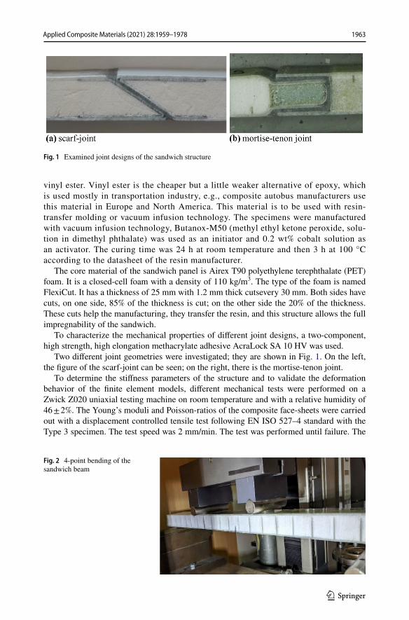
Fig. 2 4-point bending of the sandwich beam
1963Applied Composite Materials (2021) 28:1959–1978
1 3
strain components were measured with two unidirectional strain gauges perpendicular to each other on one side of the specimen. The in-plane shear modulus was carried out with the Iosipescu-test of a V-notched specimen following the standard ASTM-D5379. The test speed was 2 mm/min.
The foam core cannot be tested separately. The resin flows into the cuts of the used FlexiCut foam during manufacturing, and that can significantly influence the stiffness of the core. This effect can be examined by the test of the complete sandwich. For the sandwich beams, a 4-point bending test was performed following the standard ASTM-D7249. The test speed was 6 mm/min. The measured sandwich beam can be seen in Fig. 2.
To check the mechanical performance of the used adhesive, tensile tests were per-formed with the Type 5A specimen of the standard EN ISO 527–2 with a test speed of 1 mm/min. For the manufacturing of the specimens with the adhesive material, a poly(tetrafluoroethylene) (PTFE) mold was milled with a 4-axis milling machine. Dur-ing production, a glass plate was placed on the mold with a release gel on its surface. These measurements served only for the validation of properties on the materials data-sheet. For each type of test, five specimens were tested, average and scatter values were evaluated.
The study aims to develop a method with which the deformation behavior of the sandwich structure and its joints can be effectively modeled in full structure scale in finite element analyses. When modeling a complete structure, e.g., vehicle body, lay-ered shell elements are the most widely used instead of using solid elements. Solids allow deeper understanding of stress-state or even failure modes, but the modeling and the calculation are more time-consuming as well, so they are used generally in speci-men scale.
In this study, we derived first the stiffness parameters of the composite face-sheets from the tensile- and shear-tests, then determined an equivalent elastic modulus of the inhomo-geneous core. When having these stiffness constants, the modeling of the whole sandwich structure with a layered shell is possible. Results of the detailed finite element models are validated with the experimental tests. In the end, a new modeling technique is introduced to calculate the structure’s deformation behavior with different adhesive joint designs. In this new modeling method, we used general stiffness matrices between the layered shells representing the sandwich panel. The parameters of this matrix were derived with the help of numerical specimen-tests using detailed finite element models according to the proper joint design.
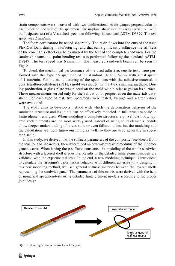
Fig. 3 Extracting stiffness parameters of the joint
1964 Applied Composite Materials (2021) 28:1959–1978
1 3
3 Modeling Method
To describe the mechanical behavior of the adhesive joints that are used to connect the components of a monocoque vehicle body is not straightforward. Of course, with given geometry and material properties, it is possible to create a detailed three-dimensional finite element model. However, due to the typical small feature sizes compared to the whole vehicle, this would require a very fine discretization, which is not feasible due to the high computational demand. To overcome this problem, it is necessary to use an alternative approach whereby elements of a shell model describing components with sufficient accuracy can be combined with simplified modeling of adhesives. In this case, it is not necessary to accurately model the exact geometry and materials of the joint areas. The most important requirement is that the model well describes the behavior of the whole vehicle and that the exact environment of the bonding is not accurately investigated. Of course, for the most critical adhesives, sub-models can be created later.
The task is illustrated in Fig. 3. Here, a 35 × 25 mm rectangular beam made of two sand-wich structures was joined together with a scarf joint. The sandwich lay-ups have the same properties as described in the above section. The left side shows the detailed model as a reference, while the right side shows the corresponding shell model. In the detailed model the face-sheets are modeled as layered shells, but the core is built of solid elements, so the exact geometry of the joints can be taken into account. The adhesives are modeled as one row of isotropic solid elements. On the other hand, in the corresponding shell model, the whole sandwich is modeled as layered shells, while the joints are represented by stiffness matrices between each shell’s coincidence nodes.
The principle of the solution used is that the overlapping node pairs at the edges of the shells representing the body components are connected with a general stiffness ele-ment. In Ansys, this element type is called Matrix27. This element can describe any connection where the geometry is undefined, but the behavior can be described by spec-ifying the stiffness matrices. Each matrix element connects two nodes, each of which has a total of six degrees of freedom: the three translational and the three rotational
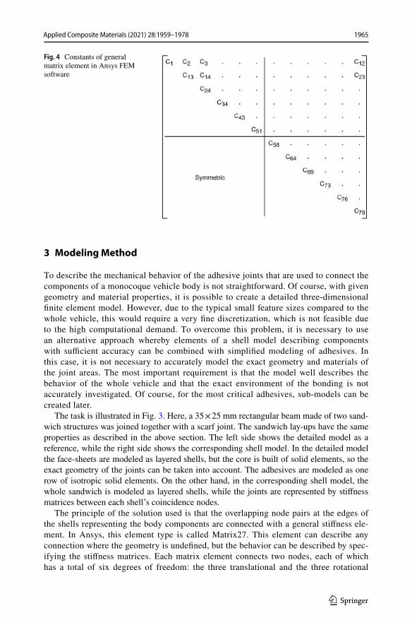
Fig. 4 Constants of general matrix element in Ansys FEM software
1965Applied Composite Materials (2021) 28:1959–1978
1 3
displacements. Assuming that the stiffness matrix is symmetric, the constants of Fig. 4 should be given. From a mechanical point of view, however, only the variables in the upper left quadrant are considered independent, so theoretically, 21 constants have to be defined for a symmetric matrix. These were properly reduced; the used variables will be explained later on.
Constants of the stiffness matrix can be determined experimentally for some typical adhesive geometries. The reference can be either a physical measurement or a detailed finite element model of the reference geometry. The reference geometry should be modeled as a shell model as well, and the matrix constants should be determined by a parameter search the way that the structure’s response at typical loads – e.g., transla-tions and rotations in different directions – match the reference.
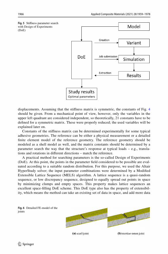
A practical method for searching parameters is the so-called Design of Experiments (DoE). At this point, the points in the parameter field considered to be possible are eval-uated according to a suitable random distribution. For this purpose, we used the Altair HyperStudy solver; the input parameter combinations were determined by a Modified Extensible Lattice Sequence (MELS) algorithm. A lattice sequence is a quasi-random sequence, or low discrepancy sequence, designed to equally spread out points in space by minimizing clumps and empty spaces. This property makes lattice sequences an excellent space-filling DoE scheme. This DoE type also has the property of extensibil-ity, which means the method can take an existing set of data in space, and add more data
Fig. 5 Stiffness parameter search with Design of Experiments (DoE)
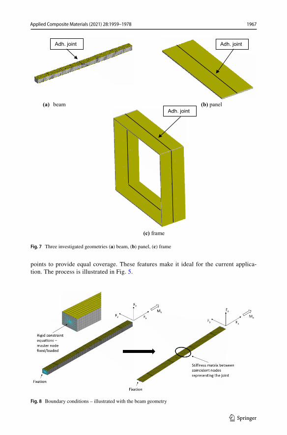
Fig. 6 Detailed FE-model of the joints
1966 Applied Composite Materials (2021) 28:1959–1978
1 3
points to provide equal coverage. These features make it ideal for the current applica-tion. The process is illustrated in Fig. 5.
(a) beam (b) panel
(c) frame
Adh. joint Adh. joint
Adh. joint
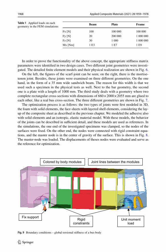
Fig. 7 Three investigated geometries (a) beam, (b) panel, (c) frame
Fig. 8 Boundary conditions – illustrated with the beam geometry
1967Applied Composite Materials (2021) 28:1959–1978
1 3
In order to prove the functionality of the above concept, the appropriate stiffness matrix parameters were identified in two design cases. Two different joint geometries were investi-gated. The detailed finite element models and their physical realization are shown in Fig. 6.
On the left, the figures of the scarf-joint can be seen; on the right, there is the mortise-tenon joint. Besides, these joints were examined on three different geometries. On the one hand, in the form of a 35 mm wide sandwich beam. The reason for this width is that we used such a specimen in the physical tests as well. Next to the bar geometry, the second one is a plate with a length of 1000 mm. The third study deals with a geometry where two complete rectangular cross-sections with dimensions of 660 × 2000 × 2055 mm are glued to each other, like a real bus cross-section. The three different geometries are shown in Fig. 7.
The optimization process is as follows: the two types of joints were first modeled in 3D, the foam with solid elements, the face-sheets with layered shell elements, considering the lay-up of the composite sheet as described in the previous chapter. We modeled the adhesive also with solid elements and an isotropic, elastic material model. With these models, the behavior of the joints can be described in sufficient detail, and these models are used as references. In the simulations, the one end of the investigated specimens was clamped, so the nodes of the surfaces were fixed. On the other end, the nodes were connected with rigid constraint equa-tions, and the master node is in the center of gravity of the surface. This is shown in Fig. 8. The master-node was loaded. The displacements of theses nodes were evaluated and serve as the reference for optimization.
Table 1 Applied loads on each geometry in the FEM simulations
Beam Plate Frame
Fx [N] 100 100 000 100 000Fy [N] 20 200 000 1 000 000Fz [N] 30 1 000 1 000 000Mx [Nm] 1 E3 1 E7 1 E9
Fix supportUnit moment
load
Joint lines between the modulesColored by body modules
Rigidconstraints
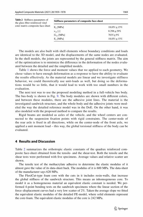
Fig. 9 Boundary conditions – global torsional stiffness of a bus-body
1968 Applied Composite Materials (2021) 28:1959–1978
1 3
The models are also built with shell elements whose boundary conditions and loads are identical to the 3D model, and the displacements of the same nodes are evaluated. In the shell models, the joints are represented by the general stiffness matrix. The aim of the optimization is to minimize the difference in the deformation of the nodes evalu-ated between the detailed and the simplified models.
Table 1 shows the force and moment values that we applied to each geometry. We chose values to have enough deformation as a response to have the ability to evaluate the results effectively. As the material models are linear and we investigate stiffness behavior, we could theoretically use unit-loads as well, but doing so the deforma-tions would be so little, that it would lead to work with too small numbers in the evaluation.
The next test was to use the proposed modeling method in a full-vehicle bus body. The bus-body is shown in Fig. 9. The body modules are shown with different colors, and between these modules, there are the adhesive joint lines. The material is the investigated sandwich structure, and the whole body and the adhesive joints were mod-eled the way the detailed reference model was in the DoE. On the other hand, it was also modeled with the proposed method to compare the results.
Rigid beams are modeled as axles of the vehicle, and the wheel centers are con-nected to the suspension fixation points with rigid constraints. The center-node of the rear axle is fixed in all directions, while on the center-node of the front axle, we applied a unit moment load – this way, the global torsional stiffness of the body can be evaluated.
4 Results and Discussion
Table 2 summarizes the orthotropic elastic constants of the quadrax reinforced com-posite face-sheet obtained from the tensile- and the shear-test. Both the tensile and the shear tests were performed with five specimens. Average values and relative scatter are shown.
The tensile test of the methacrylate adhesive to determine the elastic modulus of it almost gave the value of its data-sheet back. The modulus of it is 600 MPa. The data-sheet of the manufacturer says 620 MPa.
The FlexiCut-type foam core with the cuts in it includes resin-walls, that increase the global stiffness of the sandwich structure. This means an inhomogeneous core. To model it as a homogeneous material an equivalent elastic constant is needed. We per-formed 4-point bending tests on the sandwich specimens where the linear section of the force–displacement curves had a very low scatter of 2%. Taken the average slope we fitted the equivalent elastic modulus of the detailed FE-model, where solid elements represent the core-foam. The equivalent elastic modulus of the core is 242 MPa.
Table 2 Stiffness parameters of the glass fiber reinforced vinyl ester matrix composite face-sheet
Stiffness parameters of composite face-sheet
E2 [MPa] 18,051 ± 15%ν12 [-] 0.298 ± 29%G12 [MPa] 7035 ± 9%E1 [MPa] 18,051 ± 15%
1969Applied Composite Materials (2021) 28:1959–1978
1 3
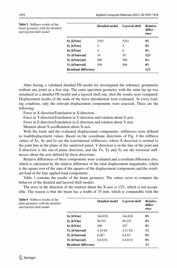
After having a validated detailed FE-model we investigated the reference geometries without any joints as a first step. The same specimen geometry with the same lay-up was simulated as a detailed FE-model and a layered shell one, then the results were compared. Displacement results of the node of the force introduction were evaluated. At every load-ing condition, only the relevant displacement components were assessed. These are the following:
Force in X-directionTranslation in X-direction.Force in Y-directionTranslation in Y-direction and rotation about Z-axis.Force in Z-directionTranslation in Z-direction and rotation about Y-axis.Moment about X-axisRotation about X-axis.With the loads and the evaluated displacement components, stiffnesses were defined
as load/displacement values. Based on the coordinate directions of Fig. 8 the stiffness values of Sx, Sy and Sz are the translational stiffnesses, where X-direction is normal to the joint line in the plane of the sandwich panel, Y-direction is in the line of the joint and Z-direction is the out-of-plane direction, and the Tx, Ty and Tz are the torsional stiff-nesses about the axis defined by these directions.
Relative differences of these components were evaluated and a resultant difference also, which is calculated by the relative difference of the total displacement magnitudes, which is the square root of the sum of the squares of the displacement components and the result-ant load of the four applied load-components.
Table 3 contains the results of the beam geometry. The values serve to compare the behavior of the detailed and layered shell models.
The error in the direction of the rotation about the X-axis is 12%, which is not accept-able. The reason is that the beam has a width of 35 mm, which is comparable with the
Table 3 Stiffness results of the beam geometry with the detailed and layered shell model
Detailed model Layered shell Relative differ-ence
Sx [kN/m] 5263 5263 0%Sy [kN/m] 4 4 0%Sz [kN/m] 6 6 0%Tx [kNm/rad] 34 30 12%Ty [kNm/rad] 990 990 0%Tz [kNm/rad] 508 508 0%Resultant difference 12%
Table 4 Stiffness results of the plate geometry with the detailed and layered shell model
Detailed model Layered shell Relative differ-ence
Sx [kN/m] 344,828 344,828 0%Sy [kN/m] 90,253 90,253 0%Sz [kN/m] 408 407 0%Tx [kNm/rad] 4.54 E8 4.51 E8 1%Ty [kNm/rad] 6.6E7 6.6 E7 0%Tz [kNm/rad] 6.6 E10 6.6 E10 0%Resultant difference 1%
1970 Applied Composite Materials (2021) 28:1959–1978
1 3
thickness that is 30 mm. It is not a shell-like geometry that is modeled with shells, so the torsional behavior is different. In reality, the vehicle bodies are shell-like structures, with a considerably smaller thickness than the other two dimensions. Thus, the next reference geometry was a plate. The results are shown in Table 4.
This geometry fulfills the basic requirements of shell models in practice. This is well reflected in the results with almost zero deviation for almost all components, so this model may already be suitable for optimizing the joints.
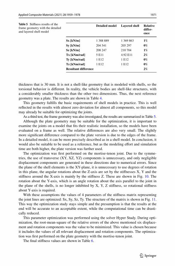
As a third test, the frame geometry was also investigated, the results are summarized in Table 5.Although the plate geometry may be suitable for the optimization, it is important to
examine the joints on a model that fits their realistic installation, so the models have been evaluated on a frame as well. The relative differences are also very small. The slightly more significant difference compared to the plate version is due to the edges of the frame. In a detailed model, it can be more precisely described as in a shell model. In conclusion, it would also be suitable to be used as a reference, but as the modeling effort and simulation time are both higher, the plate version was further used.
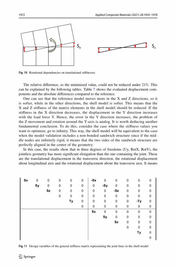
The optimization was first performed on the mortise-tenon joint. Due to the symme-tries, the use of transverse (XY, XZ, YZ) components is unnecessary, and only negligible displacement components are generated in these directions due to numerical errors. Since the plane of the shell elements is the XY-plane, it is unnecessary to use degrees of rotation in this plane, the angular rotations about the Z-axis are set by the stiffnesses X, Y and the stiffness around the X-axis is mainly by the stiffness Z. These are shown in Fig. 10. The rotation about the Y-axis, which is an angle rotation about the axis parallel to the joint in the plane of the shells, is no longer inhibited by X, Y, Z stiffness, so rotational stiffness about Y-axis is required.
With these assumptions the values of 4 parameters of the stiffness matrix representing the joint lines are optimized: Sx, Sy, Sz, Ty. The structure of the matrix is shown in Fig. 11. This way the optimization study stays simple and the presumption is that the results at the end will be accurate to an acceptable extent, while the computational time can be drasti-cally reduced.
This parameter optimization was performed using the solver Hyper Study. During opti-mization, the root-mean-square of the relative errors of the above mentioned six displace-ment and rotation components was the value to be minimized. This value is chosen because it includes the values of all relevant displacement and rotation components. The optimiza-tion was first performed on the plate geometry with the mortise-tenon joint.
The final stiffness values are shown in Table 6.
Table 5 Stiffness results of the frame geometry with the detailed and layered shell model
Detailed model Layered shell Relative differ-ence
Sx [kN/m] 1 388 889 1 369 863 1%Sy [kN/m] 204 541 205 297 0%Sz [kN/m] 208 247 210 704 1%Tx [kNm/rad] 5 E11 4.92 E11 2%Ty [kNm/rad] 1 E12 1 E12 0%Tz [kNm/rad] 1 E12 1 E12 0%Resultant difference 2%
1971Applied Composite Materials (2021) 28:1959–1978
1 3
The relative difference, so the minimized value, could not be reduced under 21%. This can be explained by the following tables. Table 7 shows the evaluated displacement com-ponents and the absolute differences compared to the reference.
One can see that the reference model moves more in the X and Z directions, so it is softer, while in the other directions, the shell model is softer. This means that the X and Z stiffness of the matrix elements in the shell model should be reduced. If the stiffness in the X direction decreases, the displacement in the Y direction increases with the load force Y. Hence, the error in the Y direction increases, the problem of the Z movement and rotation around the Y-axis is analog. It is worth deducing another fundamental conclusion. To do this, consider the case where the stiffness values you want to optimize, go to infinity. This way, the shell model will be equivalent to the case when the model validation includes a non-bonded sandwich structure since if the mid-dle nodes are infinitely rigid, it means that the two sides of the sandwich structure are perfectly aligned in the center of the geometry.
In this case, the results show that in three degrees of freedoms (Uy, RotX, RotY), the jointless geometry has more significant elongation than the one containing the joint. These are the translational displacement in the transverse direction, the rotational displacement about longitudinal axis and the rotational displacement about the transverse axis. It means
Fig. 10 Rotational dependencies on translational stiffnesses
Sx 0 0 0 0 0 -Sx 0 0 0 0 0Sy 0 0 0 0 0 -Sy 0 0 0 0
Sz 0 0 0 0 0 -Sz 0 0 00 0 0 0 0 0 0 0 0
Ty 0 0 0 0 0 -Ty 00 0 0 0 0 0 0
Sx 0 0 0 0 0Sy 0 0 0 0
Sz 0 0 00 0 0
Ty 00
Fig. 11 Design variables of the general stiffness matrix representing the joint lines in the shell-model
1972 Applied Composite Materials (2021) 28:1959–1978
1 3
that the relative difference between the models in these three degrees of freedom can only be higher since, even with infinitely rigid coupling the shell model elongation is higher. Because for the other degrees of freedom, the stiffnesses must be reduced relative to an infinitely rigid connection, and since the components are not independent of each other, this error can only be greater in these three components. Thus, a new model is needed for successful optimization.
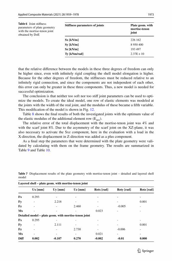
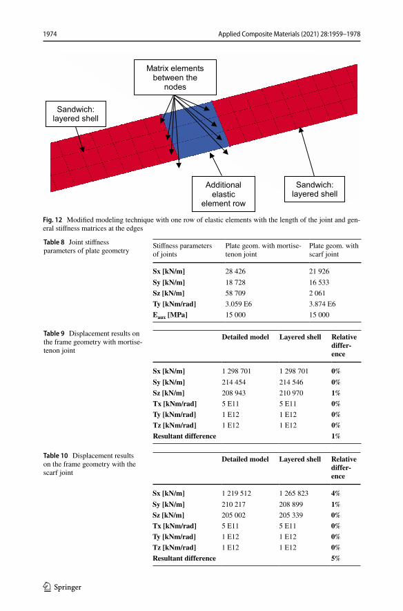
The conclusion is that neither too soft nor too stiff joint parameters can be used to opti-mize the models. To create the ideal model, one row of elastic elements was modeled at the joints with the width of the real joint, and the modulus of these became a fifth variable. This modification of the model is shown in Fig. 12.
Table 8 shows the final results of both the investigated joints with the optimum value of the elastic modulus of the additional element row (Eaux).
The relative error of the total displacement with the mortise-tenon joint was 4% and with the scarf joint 8%. Due to the asymmetry of the scarf joint on the XZ-plane, it was also necessary to activate the Sxz component, here in the evaluation with a load in the X-direction, the displacement in Z-direction was added as a plus component.
As a final step the parameters that were determined with the plate geometry were vali-dated by calculating with them on the frame geometry. The results are summarized in Table 9 and Table 10.
Table 6 Joint stiffness parameters of plate geometry with the mortise-tenon joint obtained by DoE
Stiffness parameters of joints Plate geom. with mortise-tenon joint
Sx [kN/m] 226 162Sy [kN/m] 8 950 400Sz [kN/m] 193 497Ty [kNm/rad] 2.37E + 10
Table 7 Displacement results of the plate geometry with mortise-tenon joint – detailed and layered shell model
Layered shell – plate geom. with mortise-tenon joint
Ux [mm] Uy [mm] Uz [mm] Rotx [rad] Roty [rad] Rotz [rad]
Fx 0.293 - - - - -Fy - 2.218 - - - 0.001Fz - - 2.460 - -0.005 -Mx - - - 0.023 - -Detailed model – plate geom. with mortise-tenon jointFx 0.295 - - - - -Fy - 2.111 - - - 0.001Fz - - 2.730 - -0.006 -Mx - - - 0.021 - -Diff 0.002 -0.107 0.270 -0.002 -0.01 0.000
1973Applied Composite Materials (2021) 28:1959–1978
1 3
Sandwich:layered shell
Sandwich:layered shell
Additionalelastic
element row
Matrix elementsbetween the
nodes
Fig. 12 Modified modeling technique with one row of elastic elements with the length of the joint and gen-eral stiffness matrices at the edges
Table 8 Joint stiffness parameters of plate geometry
Stiffness parameters of joints
Plate geom. with mortise-tenon joint
Plate geom. withscarf joint
Sx [kN/m] 28 426 21 926Sy [kN/m] 18 728 16 533Sz [kN/m] 58 709 2 061Ty [kNm/rad] 3.059 E6 3.874 E6Eaux [MPa] 15 000 15 000
Table 9 Displacement results on the frame geometry with mortise-tenon joint
Detailed model Layered shell Relative differ-ence
Sx [kN/m] 1 298 701 1 298 701 0%Sy [kN/m] 214 454 214 546 0%Sz [kN/m] 208 943 210 970 1%Tx [kNm/rad] 5 E11 5 E11 0%Ty [kNm/rad] 1 E12 1 E12 0%Tz [kNm/rad] 1 E12 1 E12 0%Resultant difference 1%
Table 10 Displacement results on the frame geometry with the scarf joint
Detailed model Layered shell Relative differ-ence
Sx [kN/m] 1 219 512 1 265 823 4%Sy [kN/m] 210 217 208 899 1%Sz [kN/m] 205 002 205 339 0%Tx [kNm/rad] 5 E11 5 E11 0%Ty [kNm/rad] 1 E12 1 E12 0%Tz [kNm/rad] 1 E12 1 E12 0%Resultant difference 5%
1974 Applied Composite Materials (2021) 28:1959–1978
1 3
It can be seen that the maximal error rate is 5%, and no single component exceeds 5%. Thus, the method is suitable for modeling sandwich panels with layered shells and their joints with general stiffness matrices.
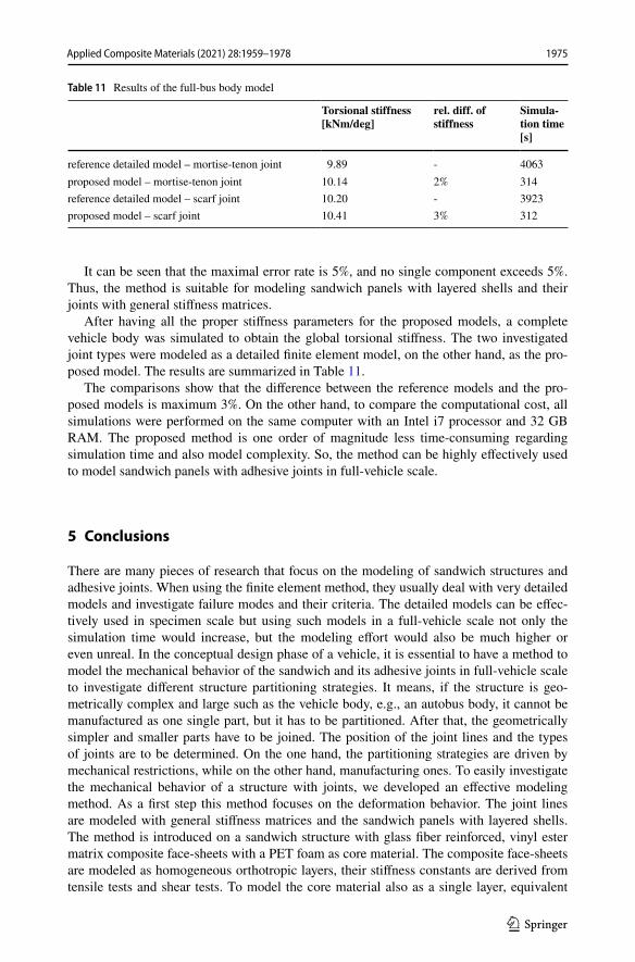
After having all the proper stiffness parameters for the proposed models, a complete vehicle body was simulated to obtain the global torsional stiffness. The two investigated joint types were modeled as a detailed finite element model, on the other hand, as the pro-posed model. The results are summarized in Table 11.
The comparisons show that the difference between the reference models and the pro-posed models is maximum 3%. On the other hand, to compare the computational cost, all simulations were performed on the same computer with an Intel i7 processor and 32 GB RAM. The proposed method is one order of magnitude less time-consuming regarding simulation time and also model complexity. So, the method can be highly effectively used to model sandwich panels with adhesive joints in full-vehicle scale.
5 Conclusions
There are many pieces of research that focus on the modeling of sandwich structures and adhesive joints. When using the finite element method, they usually deal with very detailed models and investigate failure modes and their criteria. The detailed models can be effec-tively used in specimen scale but using such models in a full-vehicle scale not only the simulation time would increase, but the modeling effort would also be much higher or even unreal. In the conceptual design phase of a vehicle, it is essential to have a method to model the mechanical behavior of the sandwich and its adhesive joints in full-vehicle scale to investigate different structure partitioning strategies. It means, if the structure is geo-metrically complex and large such as the vehicle body, e.g., an autobus body, it cannot be manufactured as one single part, but it has to be partitioned. After that, the geometrically simpler and smaller parts have to be joined. The position of the joint lines and the types of joints are to be determined. On the one hand, the partitioning strategies are driven by mechanical restrictions, while on the other hand, manufacturing ones. To easily investigate the mechanical behavior of a structure with joints, we developed an effective modeling method. As a first step this method focuses on the deformation behavior. The joint lines are modeled with general stiffness matrices and the sandwich panels with layered shells. The method is introduced on a sandwich structure with glass fiber reinforced, vinyl ester matrix composite face-sheets with a PET foam as core material. The composite face-sheets are modeled as homogeneous orthotropic layers, their stiffness constants are derived from tensile tests and shear tests. To model the core material also as a single layer, equivalent
Table 11 Results of the full-bus body model
Torsional stiffness [kNm/deg]
rel. diff. of stiffness
Simula-tion time [s]
reference detailed model – mortise-tenon joint 9.89 - 4063proposed model – mortise-tenon joint 10.14 2% 314reference detailed model – scarf joint 10.20 - 3923proposed model – scarf joint 10.41 3% 312
1975Applied Composite Materials (2021) 28:1959–1978
1 3
stiffness constants are determined via bending tests of the sandwich. Validation of the model of the complete sandwich was performed with a 4-point bending test. The following conclusions of our method development be drawn:
(1) we developed an effective modeling method to model the deformation behavior of sandwich structures with adhesive joints by using layered shells for the sandwich panels and general stiffness matrices for the joint regions, where the stiffness parameters of the matrices were obtained by the design of experiments based on detailed finite element models validated with mechanical tests;
(2) taking 4 independent variables Sx, Sy, Sz, Ty of a general stiffness matrix with 21 parameters and one elastic constant in the optimization run of the DoE analysis brings accurate results. The relative difference of the displacement components and the total magnitude between the proposed equivalent finite element model and the reference detailed model stayed under 5% by investigating beam-, plate- and frame-like geom-etries with scarf-joint and mortise-tenon joint lines. The X-direction is normal to the joint line in the plane of the sandwich panel, Y-direction is in the line of the joint and Z-direction is the out-of-plane direction;
(3) with the proposed method, high computational cost can be saved. The computational time of the global torsional stiffness calculation of a polymer composite bus-body was one order of magnitude faster than the same bus-body with detailed modeling. The simulations were run on the same hardware. When investigating different designs or performing optimization tasks of a vehicle body in the conceptual design phase, this is a highly effective method.
A further plan to this research is to enhance this modeling method with the failure of the joints by using element birth–death feature and after that including this procedure in a framework, with which the partitioning strategies of a vehicle body can be investigated automatically.
6 Data Availability Statement
The datasets generated during and/or analysed during the current study are available from the corresponding author on reasonable request.
Funding Open access funding provided by Budapest University of Technology and Economics. The project is funded by the National Research, Development and Innovation (NKFIH) Fund, Project title: "Produc-tion of polymer products by short cycle time, automatized production technology for automotive applica-tions, with exceptional focus on the complexity and recyclability of the composite parts"; The application ID number: NVKP_16-1–2016-0046. The developers are grateful for the support. The research reported in this paper was supported by the BME-Nanotechnology FIKP grant (BME FIKP-NAT).
Declarations
Conflicts of Interest The authors declare no conflict of interest.
Open Access This article is licensed under a Creative Commons Attribution 4.0 International License, which permits use, sharing, adaptation, distribution and reproduction in any medium or format, as long as you give appropriate credit to the original author(s) and the source, provide a link to the Creative Commons
1976 Applied Composite Materials (2021) 28:1959–1978
1 3
licence, and indicate if changes were made. The images or other third party material in this article are included in the article’s Creative Commons licence, unless indicated otherwise in a credit line to the mate-rial. If material is not included in the article’s Creative Commons licence and your intended use is not per-mitted by statutory regulation or exceeds the permitted use, you will need to obtain permission directly from the copyright holder. To view a copy of this licence, visit http:// creat iveco mmons. org/ licen ses/ by/4. 0/.
References
1. Dilger, K.: Selecting the right joint design and fabrication techniques. In: Dillard, D. (ed) Advances in structural adhesive bonding, vol. 1, pp. 295–315. Woodhead Publishing (2010)
2. Crane, R., Dillingham, G., Oakley, B.: Progress in the Reliability of Bonded Composite Structures. Appl. Compos. Mater. 24, 221–233 (2017). https:// doi. org/ 10. 1007/ s10443- 016- 9523-2
3. Kim, J.-S., Shim, G.-S., Baek, D., Back, J.-H., Jang, S.-W., Kim, H.-J., Choi, J.-S., Yeom, J.-S.: UV/UV step-curing of optically clear acrylate adhesives for mobile devices. Express Polym Lett 13(9), 794–805 (2019). https:// doi. org/ 10. 3144/ expre sspol ymlett. 2019. 68
4. Geier, N., Pereszlai, Cs.: Analysis of characteristics of surface roughness of machined CFRP com-posites. Period. Polytech. Mech. Engg. 64(1), 67–80 (2020). https:// doi. org/ 10. 3311/ PPme. 14436
5. Gao, Q., Li, Y., Wang, H., Liu, W., Shen, H., Zhan, X.: Effect of scanning speed with UV laser cleaning of adhesive bonding tensile properties of CFRP. Appl. Compos. Mater. 26, 1087–1099 (2019). https:// doi. org/ 10. 1007/ s10443- 019- 09768-4
6. Manalo, A., Aravinthan, T.: Behaviour of glued fibre composite sandwich structure in flexure: Experiment and Fibre Model Analysis. Mater. Des. 39, 458–468 (2012). https:// doi. org/ 10. 1016/j. matdes. 2012. 02. 052
7. Navarro, P., Abrate, S., Aubry, J., Marguet, S., Ferrero, J.F.: Analytical modeling of indentation of composite sandwich beam. Compos. Struct. 100, 79–88 (2013). https:// doi. org/ 10. 1016/j. comps truct. 2012. 12. 017
8. Paczos, P., Wichniarek, R., Magnucki, K.: Three-point bending of sandwich beam with special structure of the core. Compos. Struct. 201, 676–682 (2018). https:// doi. org/ 10. 1016/j. comps truct. 2018. 06. 077
9. Anish Kumar, A., Chakrabarti, A.: Failure mode analysis of laminated composite sandwich plate. Eng. Fail. Anal. 104, 950–976 (2019). https:// doi. org/ 10. 1016/j. engfa ilanal. 2019. 06. 080
10. Kpeky, F., Boudaoud, H., Abed-Meraim, F., Daya, E.M.: Modeling of viscoelastic sandwich beams using solid–shell finite elements. Compos. Struct. 133, 105–116 (2015). https:// doi. org/ 10. 1016/j. comps truct. 2015. 07. 055
11. Ferdous, W., Manalo, A., Aravinthan, T., Fam, A.: Flexural and shear behaviour of layered sand-wich beams. Constr. Build. Mater. 173, 429–442 (2018). https:// doi. org/ 10. 1016/j. conbu ildmat. 2018. 04. 068
12. Vidal, P., Giunta, G., Gallimard, L., Polit, O.: Modeling of composite and sandwich beams with a generic cross-section using a variable separation method. Compos. B Eng. 2019(165), 648–661 (2019). https:// doi. org/ 10. 1016/j. compo sitesb. 2019. 01. 095
13. Odessa, I., Frostig, Y., Rabinovitch, O.: Modeling of interfacial debonding propagation in sandwich panels. Int. J. Solids Struct. 148–149, 67–78 (2018). https:// doi. org/ 10. 1016/j. ijsol str. 2017. 10. 014
14. Takács, L., Szabó, F.: Experimental and Numerical Failure Analysis of Adhesive Joint of Glass Fiber Reinforced Polymer Composite. Periodica Polytechnica Mechanical Engineering 64(1), 88–95 (2020). https:// doi. org/ 10. 3311/ PPme. 15106
15. Assaad, J., Chakar, E., Zéhil, G.-P.: Testing and modeling the behavior of sandwich lightweight panels against wind and seismic loads. Eng. Struct. 175, 457–466 (2018). https:// doi. org/ 10. 1016/j. engst ruct. 2018. 08. 041
16. Tang, J., Chen, X., Yang, K.: Evaluating Structural Failure of Load-Carrying Composite Box Beams with Different Geometries and Load Conditions. Appl. Compos. Mater. 26, 1151–1161 (2019). https:// doi. org/ 10. 1007/ s10443- 019- 09776-4
17. Mårtensson, P., Zenkert, D., Åkermo, M.: Cost and weight efficient partitioning of composite auto-motive structures. Polym. Compos. 38, 2174–2181 (2017). https:// doi. org/ 10. 1002/ pc. 23795
18. Dragoni, E., Brinson, H.F.: Modeling and optimization of the sandwich beam specimen in three-point bending for adhesive bond characterization. Int. J. Adhes. Adhes. 68, 380–388 (2016). https:// doi. org/ 10. 1016/j. ijadh adh. 2015. 12. 014
1977Applied Composite Materials (2021) 28:1959–1978
1 3
19. Van Loock, F., Thouless, M.D., Fleck, N.A.: Tensile fracture of an adhesive joint: the role of crack length and of material mismatch. J. Mech. Phys. Solids 130, 330–348 (2019). https:// doi. org/ 10. 1016/j. jmps. 2019. 06. 004
20. Jiang, X., Qiang, X., Kolstein, H., Bijlaard, F.: Analysis on Adhesively-Bonded Joints of FRP-steel Composite Bridge under Combined Loading: Arcan Test Study and Numerical Modeling. Polymers (Basel) 8(1), 18 (2016). https:// doi. org/ 10. 3390/ polym 80100 18
21. Yu, Y., Hou, W.-B., Hu, P., Ying, L., Akhmet, G.: Elastic constants for adhesively bonded corrugated core sandwich panels. Compos. Struct. 176, 449–459 (2017). https:// doi. org/ 10. 1016/j. comps truct. 2017. 05. 057
22. Yu, H., Bai, Y.L., Dai, J.G., Gao, W.Y.: Finite Element Modeling for Debonding of FRP-to-Concrete Interfaces Subjected to Mixed-Mode Loading. Polymers (Basel) 9(9), 438 (2017). https:// doi. org/ 10. 3390/ polym 90904 38
23. Cen, B., Liu, Y., Zeng, Z., Wang, J., Lu, X., Zhu, X.: Mechanical behavior of novel GFRP foam sandwich adhesive joints. Compos. B Eng. 130, 1–10 (2017). https:// doi. org/ 10. 1016/j. compo sitesb. 2017. 07. 034
24. Li, X., Liu, Z., Hu, L., Wang, Y., Lei, B., Huang, X.: Numerical Investigation of T-joints with 3D Four Directional Braided Composite Fillers Under Tensile Loading. Appl. Compos. Mater. 24, 171–191 (2017). https:// doi. org/ 10. 1007/ s10443- 016- 9520-5
25. Khosravani, M.R., Anders, D., Weinberg, K.: Influence of strain rate on fracture behavior of sand-wich composite T-joints. Euro. J. Mech. A Solids 78, 103821 (2019). https:// doi. org/ 10. 1016/j. eurom echsol. 2019. 103821
26. Di Bella, G., Galtieri, G., Borsellino, C.: Three-Point Flexural Properties of Bonded Reinforce-ment Elements for Pleasure Craft Decks. Appl. Compos. Mater. 25, 21–34 (2018). https:// doi. org/ 10. 1007/ s10443- 017- 9605-9
27. Budhe, S., Banea, M.D., de Barros, S., da Silva, L.F.M.: An updated review of adhesively bonded joints in composite materials. Int. J. Adhes. Adhes. 72, 30–42 (2017). https:// doi. org/ 10. 1016/j. ijadh adh. 2016. 10. 010
Publisher’s Note Springer Nature remains neutral with regard to jurisdictional claims in published maps and institutional affiliations.
1978 Applied Composite Materials (2021) 28:1959–1978