Embed Size (px)
Citation preview

An Effective Method of Fingerprint Classification Combined with AFIS
Ching-Tang Hsieh, Shys-Rong Shyu, Chia-Shing Hu Department of Electrical Engineering, Tamkang University, Tamsui, Taipei Hsien, Taiwan 25137, Republic of China
Abstract. In this paper, we present a fast and precise method for fingerprint classification. The proposed method directly extracts the directional information from the thinned image of the fingerprint. We use an octagon mask to search the center point of the region of interest and consider both the direction information and the singular points in the region of interest to classify the fingerprints. In the system, not only is the amount of computation reduced but also can the extracted information be used for identification on AFIS. The system has been tested on the NIST special fingerprint database 4. For the 4000 images in this database, 2000 images are randomly chosen by computer and classified. The classification accuracy reaches 93.1% with no rejection for 4-class classification problem. Keywords: Biometrics; Fingerprint classification; Wavelets; Poincare index; Singular point detection
1. Introduction Fingerprints are the innate feature of mankind. The patterns of fingerprints become fixed when a person is about 14
years or older. Due to the invariance and uniqueness of fingerprints, they are used as the tool for crime investigation by the government as far back as A.D. 1897. So far, fingerprints have been used for more than 100 years as the most popular biometric signs of identity. With the large fingerprints database, fingerprint classification is an important subproblem for the automatic fingerprint identification system (AFIS) and automatic fingerprint recognition system (AFRS) [1]. Fingerprint classification improves the computational complexity substantially by reducing the number of candidate matches to be considered, so an effective indexing scheme can be of great help. In this paper we propose a an effective method of fingerprint classification, we extract the only 2D feature vector of the orientation field directly derived from the thinned images. We first use the enhancement algorithm of fingerprint images presented in Pattern Recognition, vol. 36 [10]. We compute the orientation following the skeleton of thinned image, so it is more effective without another enhancement for AFIS. Then we use an octagon mask to fast search the center point of the region of interest and extract the feature from the lower half of the octagon mask. Finally, we simplify the feature vectors and use the two-stage classifier to analyze the features and output the result of classification.
The rest of the paper is organized as follows. In Section 2, we briefly review the algorithm of fingerprint enhancement and describe the computation of orientation filed. In Section 3, we detailed search for the centers of the regions of interest using the octagon mask and feature extraction for classification. Then, Section 4 presents our two-stage classification scheme and Section 5 shows the experimental results tested on the NIST-4 database. The conclusions are presented in Section 6.
2. Orientation field computation
For the fingerprint classification, the global texture information is more important than the local direction. For an automatic fingerprint identification/recognition system, the algorithm we presented in [10] has shown good results of enhancement, so we combine the fingerprint classification AFIS/AFRS to reduce computation. We describes the processing in the flowing subsections.
2.1 Enhancement algorithm review
In an earlier work in Pattern Recognition, vol. 36 [10], we propose an effective enhancement method that combines the texture unit of global information with the ridge orientation of local information. Based on the characteristic of hierarchical framework of multiresolution representation, the wavelet transform is used to decompose the fingerprint image into different spatial/frequency sub-images by checking the “approximation region”. In considering the global information, all the texture units within an approximation sub-image are processed by textural filters. Based on the hierarchical relationship of each resolution, all other sub-images are processed according to the related texture units within the approximation sub-image. Similarly, the directional compensation is implemented by voting technique in considering the orientation of local neighboring pixels. After these two enhancement processes, the improved fingerprint image is obtained by the reconstruction process of wavelet transform. The flowchart is shown as follows

and the results are shown in Fig.2.
2.2 Orientation field computation
Because the thinned image has shown the clear characteristic of ridges and valleys on fingerprints, we use a 5×5 mask to compute the orientation following the skeleton of thinned image. The orientation is quantified by the 5×5 mask to 8 directions, S1 to S8, as shown in Fig.6, there are 0(π ),π /8, π /4,3π /8, π /2,5π /8,3π /4 and 7π /8, respectively. And the pixels of each block belong to the direction
pD as
)max( 8,....,1p iiSDirectionD
== (1)
and
∑∈
×=Myx
ii yxcyxpS),(
),(),( (2)
where M is the 5×5 mask, ),( yx is all the pixels in the mask, (x,y)pi is the gray value of pixel (x, y) in the ith directional mask and ),( yxc is the gray value of the corresponding pixel (x, y) in the thinned image, respectively. When
the computation is completed, each pixel near the skeleton will be given a directional value that they belong to. Fig.3 shows the examples of the processing. Then we divide the image into (height/5) × (width/5) blocks and assign a directional value bD to the block by
( )
⎟⎟⎟
⎠
⎞
⎜⎜⎜
⎝
⎛=
∑∈
N
yx, Direction Direction D blocky)(x,
b (3)
where N is the number of the pixels with direction values in the block. At this stage, the orientation field has been estimated but is still noisy, we need to smooth it and interpolate values
for the noisy region. We use a 5×5 mask to smooth and interpolate the field by replacing the directional value of center point with the directional value that appears in the mask for most times. After the smoothing, the orientation field is ready for the extraction of the feature for classifying. The result is shown in Fig.4. Figure 5 shows the comparison between the original image and the orientation field.
Normalization
Wavelet decomposition
Global texture filtering
Input fingerprint image
Local direction compensation
Wavelet reconstruction
Enhanced fingerprint image
Fig.2 Results of the enhancement, (a) original fingerprint image, (b) normalized image, (c) the result of global texture unit filtering, (d) the result of local directional compensation, (e) thinned image.
Fig.1. The flowchart of fingerprints enhancement on identification system (AFIS) in [10]

Fig.3 The example processing of the orientation estimation, (a) the partial skeleton of the thinned image, (b), (c), (d) the
sequence of processing.
Fig.4 The result of computation by the 5×5 mask, (a) the original image, (b) the thinned image, (c) the result of the first
stage computation, (d) the orientation field, (e) the smoothed orientation field.
3. Feature extraction
In the stage of feature extraction, the Poincare index, which is derived from continuous curves, is the most popular approach for the singularities based classification [1] [3-5]. However, as mentioned above, the approach is especially hard to deal with the noisy or dim images that lose the information about the regions of singularities. In our method, we find a center of a similar circle from the orientation field and extract the features around the center for classification. We also use the Poincare index but only for detecting that whether the region of interest includes any singular points or not, and the computation will be addressed in a later section. In the next subsection, we first make a discussion on the structures of each class of fingerprints and then describe the detail of the feature extraction.
3.1 The discussion on the structures of each class
Before extracting the feature, we have to know what feature is helpful to classification and which feature has the most discriminability for fingerprint pattern. So, here we make the discussions about the regular characteristic of each fingerprint class first. We divide the region around the center into four blocks, left upper, left lower, right upper and right lower, and we discuss the directional features on each block for 4-class problem below: 1. Arch (and tented arch): the orientations of texture around the center are symmetrical and the orientations of each
block are all downward and outward. (see Fig.6) 2. Left loop: the texture orientations of the two blocks above the center are symmetrical and downward, and the
orientations of the two lower blocks are both towards the left. (see Fig.7)
(a) (b) (c) (d)
Fig.5 The comparison between the original image and the orientation field.
Fig.6 The 8 directions 5×5 mask represented, C is the center pixel of the mask.

3. Right loop: the texture orientations of the two blocks above the center are symmetrical and downward, and the orientations of the two lower blocks are both towards the right. (see Fig.8) Whorl: the texture orientations of the left and right blocks are symmetrical each other and downward, and the
orientations of the blocks above the center and that are under the center are outwards and inwards, respectively. By observing the appearances described above, we could draw the conclusion that the orientations of the blocks
above the center are consistent in that they are all symmetrical and are downward and outward and the orientations of the blocks under the center have the discriminability of each fingerprint class.
Hence, we use the information above the center to locate the center point of the region of interest and extract the feature from the information under the center point to classify them. The detailed process is described in the next subsection.
3.2 Center point location
After we accomplished the computation of the orientation field, we still have to determine the region of interest (ROI) to extract the most representative features for classification. Locating the center point of the region of interest is an essential step that can influence the accuracy of the classification. We present a fast method to search and locate the center of the region of interest using an octagon mask. In the octagon mask, for the region of each triangle we assign different score with different conditions for the corresponding pixels of the orientation field. As shown in Fig.3, the mask we used is designed by considering the similar structure of a circle and the values 1, 3, 5 and 7 represent the direction S1, S3, S5 and S7 respectively, as shown in Fig.10. We attempt to find the center of a similar circle from the orientation field of fingerprints, so that the summation of the correlation between the mask and a pattern, if that is an ideal circle, will be the highest. And considering the symmetric of center of fingerprints as mentioned above, we assign different weight for each triangle of the octagon. We increase the weight of upper and both side triangles to emphasize the characteristic of the center point, and the weight of each triangle is shown as Fig.11.
Fig.9 The orientation characteristic of whorl class and its orientations of four blocks around the center
Fig.8 The orientation characteristic of right loop classand its orientations of four blocks around the center
Fig.7 The orientation characteristic of left loop class and its orientations of four blocks around the center
Fig.6 The orientation characteristic of arch class and itsorientations of four blocks around the center
Fig.11 The weight of each triangle of the octagon
Fig.10 The mask for capturing the center point; X denotes the evaluated position of possible center point.
2
1 1
2 2
5 50

The center point location algorithm includes following steps: Step 1: Let D be the orientation field with D (i, j) representing the direction at pixel (i, j). Step 2: Define an octagon mask M including four directions and eight weights. Step 3: Initialize a label image L with the same size of D. L is used to indicate the center point of the region of interest. Step 4: For each pixel )( , cc ji in D, define a local region S with the same size of M. The values of summation L )( , cc ji
can be estimated by using the following formula:
weightjidirjidirjiLSjiMji
mmccmm
×−= ∑∈∈ ),(,),(
, ),(),()( (4)
where ),( jidir is the direction at pixel ),( ji in M and ),( mm jidir is the direction at pixel ),( mm ji in S. The weight is
defined as Fig.11. Step 5: Search for the minimum value and assign the coordinates as the center point of the region of interest. If there are two equal minimum values in L, we will assign the coordinates of the middle point of them as the center point.
Fig.12 The results of the center point location, (a) the result of an arch fingerprint, (b) the label image of (a), (c) the
result of a left fingerprint, (d) the label image of (c). 3.3 Feature extraction As mentioned in section 3.1, the orientation under the center point can most demonstrate the characteristics of each fingerprint class most, so we extract the directional feature of the lower portion of the octagon for classification. Fig.14 shows the region we extract the feature from.
We determine the similarities of each direction in triangles to deduce the feature as the input of classification by using the following formulas:
In the left half the L-score is estimated by
∑∈
⎪⎪⎪
⎩
⎪⎪⎪
⎨
⎧
=
=−=
=−=
==
==
×=−MLji
ji
ji
ji
ji
ji
ji
S
jidirS
jidirS
jidirS
jidirS
weightSscoreL_,
,
,
,
,
,
,
,0 others,
,8or 6),( when 5
,7),( when 10
,4or 2),( when5
,3),( when 10
(5)
In the right half the R-score is estimated by
(a) (b) (c) (d)
(a) (b) Fig.14 The regions we extract the features from. Fig.13 Some examples of the location on poor quality
images, (a) a large number of information is lost, (b) the information of the core is lost.

∑∈
⎪⎪⎪
⎩
⎪⎪⎪
⎨
⎧
=
==
==
=−=
=−=
×=−MRji
ji
ji
ji
ji
ji
ji
S
jidirS
jidirS
jidirS
jidirS
weightSscoreR_,
,
,
,
,
,
,
,0 others,
,8or 6),(n whe5
,7),( when 10
,4or 2),( when 5
,3),( when 10
(6)
where dir( i, j) is the direction of the corresponding pixel in the orientation field and there are also different weights in each triangle as shown in Fig.15. Finally, we can obtain a 2D feature vector (L-score, R-core) and then we use the vectors for classification.
4. Classification
Because the derived features describes the directional information on blocks (left lower and right lower), if there are more than one direction in a block, the features will not be able to show the clear feature with some direction. In other words, they will get a low score on the block that includes the singular points. For this, we detect the singular points in the block with the low score by Poincare index in first stage and classify them into one of three classes of right loop, left loop and whorl. For the others with the clear directional characteristics else, we classify them into one of four classes by c-mean in second stage. The flowchart of classification is shown in Fig.16.
Fig.15 The weights for feature extraction Fig.16 The flowchart of our fingerprint classification
4.1 First stage: filtering the image including singularities
We use the Poincare index to filter the images including singular points in the stage. As for fingerprints images, a double care point has a Poincare as 1m a core point 1/2 and a delta point -1/2. The Poincare index at pixel (x, y), which is enclosed by a digital curve, the boundary of the blocks in the paper, can be computed as follows:
Poincare(x, y) = ∑Ψ
=
∆N
k
k0
)(21π
(7)
where
⎪⎪⎪
⎩
⎪⎪⎪
⎨
⎧
−
−≤+
<
=∆
,),(
,2
)( ),(
,2
)( ),(
)(
otherwisek
kifk
kifk
k
δπ
πδδπ
πδδ
(8)
and ))(),(())(),(()( iiiik yxyx ΨΨΘ−′Ψ′ΨΘ=δ (9)
i′ = (i+1) mod ΨN (10)

Θ is the orientation field, )(ixΨ and )(iyΨ denote the ith point coordinate (x, y) of the enclosed curveΨ .
There are three cases that the block probably includes the singular points, it is described as follows: 1. The case of left loop; when the loop feature is not apparent, the directional features are usually unclear due to the
fact that some block includes the delta points as shown in Fig.17. Hence if we find that the directional feature towards the left in L-score is higher than a predefined threshold and a delta point detected by Poincare index in the right block, it is classified as the class of left loop at the first stage.
2. The case of right loop; the same as left loop, when the loop feature is not apparent, the directional features are usually unclear due to the fact that some block includes the delta points as shown in Fig.18. Hence if we find that the directional feature towards the right in R-score is higher than a predefined threshold and a delta point detected by Poincare index in the left block, it is classified as the class of right loop at the first stage.
3. The case of whorl; as shown in Fig.19 and Fig.20, when the texture of a whorl is large, the region of interest we derived in section 3.2 probably includes a singular point. Hence if we find that the directional feature towards the left in R-score or towards the right in L-score is higher than a predefined threshold and a core point detected by Poincare index in the corresponding block, it is classified as the class of whorl at the first stage. Furthermore, in a few situations there the core point will be replaced by a delta point and we also assign that as the class of whorl as shown in Fig.21.
Fig.21 The situations that the core point is replaced be a delta in the case of whorl.
4.2 Second stage: classification At the second stage, we classify the fingerprint without the first stage by the c-mean classifier. After the second stage classification by c-means classifier, it is all done for the fingerprint classification. The examples of our results are shown in Fig.22 and that shows the singular points detected at the fist stage such as (c), (d) and (f). And Fig.23 shows that the proposed method also can classify the noisy and dim images correctly. The letters A, R, L and W in these
Fig.17 The left loop includes a delta point in the right block and the L-score is high leftward.
Fig.18 The right loop includes a delta point in the left block and the R-score is high on
Fig.19 The whorl includes a core point in the left block and the R-score is high on leftward.
Fig.10 The whorl includes a core point in the right block and the L-score is high on rightward.

figures represent the class of arch, right loop, left loop and whorl, respectively.
Fig.22 The results of fingerprint classification, and there are the singular points in (c), (d) and (f).
Fig.23 The results of the images with poor quality.
5. Experimental results
In our experiment we use the NIST special fingerprint database 4 (NIST-4) that contains 4000 gray-scale fingerprints images from 2000 fingerprints, and they are distributed evenly over the five classes (arch (A), tented arch (T), left loop (L), right loop (R) and whorl (w)). The classification of each fingerprints are stored in the NIST IHead id field of each file. In our results of the experiment for the 4-class classification problem, the classes A and T are merged into one class and the class index of one image in the NIST-4 database does not necessarily belong to only one class. So we consider our result of the classification to be correct if it matches the one of the class index. This approach has also been adopted by other researchers [1, 3]. We test our algorithm with 2000 fingerprints chosen randomly by computer from NIST-4 data base and the results are shown in Table 1 where the first column shows the class index in the image file header and the fist row labels the assigned class using our method. The table also shows the fail rejection rate (FRR) and the fail accept rate (FAR) in the last column and row, respectively. The accuracy is 93.1% (1862/2000) with zero rejection in our system.
Table 1 Our experimental results for 4-class problem on NIST-4 database with no rejection
Exp. as True
Whorl Left loop Right loop Arch FRR
Whorl 374 10 6 0 4.1% Left loop 2 344 3 43 12.5% Right loop 1 2 354 45 11.9% Arch 0 16 10 790 3.3% FAR 0.8% 7.8% 5.1% 10.1%

Table 2 The experimental results of traditional singular based method for 4-class problem with no rejection
Exp. as True
Whorl Left loop Right loop Arch Unknown
Whorl 301 10 11 5 63 Left loop 12 334 3 18 25 Right loop 11 5 345 23 18 Arch 9 16 10 760 21
Table 3 The experimental results with pseudo ridge tracing [16] for 4-class problem with no rejection
Exp. as True
Whorl Left loop Right loop Arch Unknown
Whorl 727 27 26 8 7 Left loop 25 759 5 26 2 Right loop 24 14 740 41 4 Arch 22 38 18 1482 5
From the result table we can see that most of the misclassifications are between the loops and the whorls. The main reason is due to the rotation of loops and the similar pattern between loops and arch, and some of the misclassifications are due to the limitation of the mask size used to extract features; so that the mask cannot include the helpful features like singular points from the images with the lager pattern. Besides, some images have the wrong center of the region of interest located at first stage because of the poor image quality. (See Fig.24)
Fig.24 The misclassified images, (a) a whorl as a left loop, (b) a left loop as an arch, (c) a right loop as an arch, (d)
a right loop as an arch. We also compare the results with the traditional method of singularity based on the same database as shown in
Table 2. We can see that the major difference is that the number of the images that cannot be classified by the traditional classifier is up to 127 and the whorl type is up to 63. So the accuracy of the system with singularity based is only 87% for 4-class problem on the same database. There is a complementary texture for the classification of the whorl type using the pseudo ridge tracing presented by Zhang and Yan [16] in recent research and their classification accuracy reaches 92.7% for the 4-class problem on NIST-4 database without rejection as compared in Table 3.
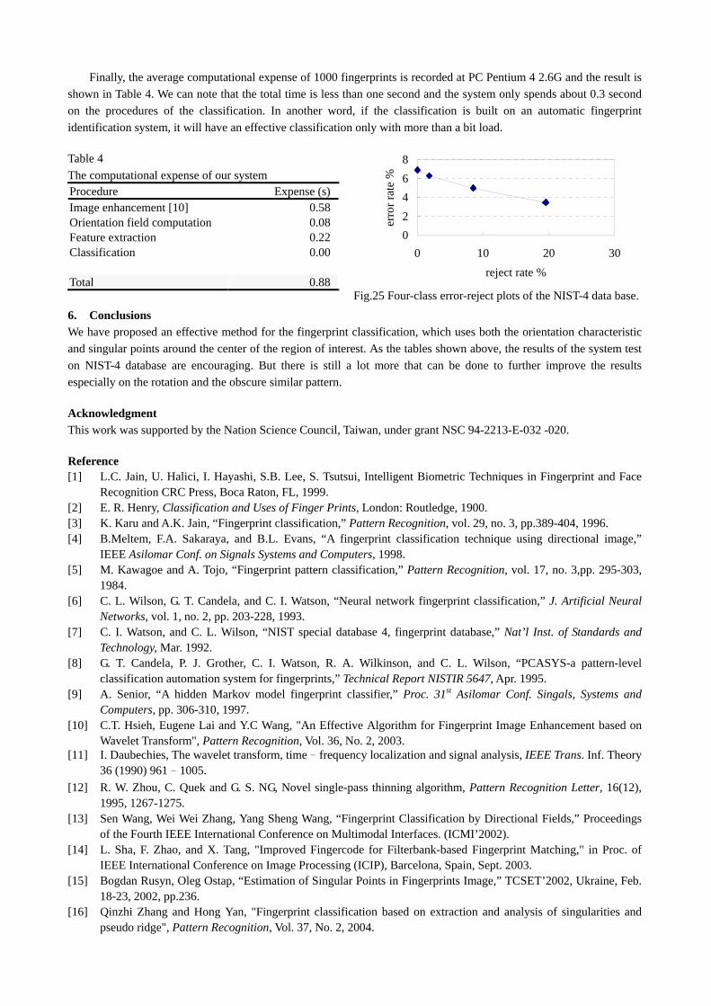
However, there are still many poor quality images, like stained and dim images, on NIST-4 database and they are difficult to recognize even for human. If we discard such obscure images by introducing the rejection scheme, the accuracy of our classification will rise to 93.7% with 1.8 reject rate, 95% with 8.5% reject rate and 96.5% with 19.5% reject rate. Fig.25 shows the corresponding graph of the rejection rate and Fig.26 shows the examples of the rejected images with poor quality
Fig.26 The examples of the rejected images, (a) the noisy image, (b), (c) the faint images, (d) the over- inked image.
Rejected
Finally, the average computational expense of 1000 fingerprints is recorded at PC Pentium 4 2.6G and the result is shown in Table 4. We can note that the total time is less than one second and the system only spends about 0.3 second on the procedures of the classification. In another word, if the classification is built on an automatic fingerprint identification system, it will have an effective classification only with more than a bit load.
Table 4 The computational expense of our system Procedure Expense (s)Image enhancement [10] 0.58Orientation field computation 0.08Feature extraction 0.22Classification 0.00 Total 0.88
6. Conclusions We have proposed an effective method for the fingerprint classification, which uses both the orientation characteristic and singular points around the center of the region of interest. As the tables shown above, the results of the system test on NIST-4 database are encouraging. But there is still a lot more that can be done to further improve the results especially on the rotation and the obscure similar pattern.
Acknowledgment This work was supported by the Nation Science Council, Taiwan, under grant NSC 94-2213-E-032 -020.
Reference [1] L.C. Jain, U. Halici, I. Hayashi, S.B. Lee, S. Tsutsui, Intelligent Biometric Techniques in Fingerprint and Face
Recognition CRC Press, Boca Raton, FL, 1999. [2] E. R. Henry, Classification and Uses of Finger Prints, London: Routledge, 1900. [3] K. Karu and A.K. Jain, “Fingerprint classification,” Pattern Recognition, vol. 29, no. 3, pp.389-404, 1996. [4] B.Meltem, F.A. Sakaraya, and B.L. Evans, “A fingerprint classification technique using directional image,”
IEEE Asilomar Conf. on Signals Systems and Computers, 1998. [5] M. Kawagoe and A. Tojo, “Fingerprint pattern classification,” Pattern Recognition, vol. 17, no. 3,pp. 295-303,
1984. [6] C. L. Wilson, G. T. Candela, and C. I. Watson, “Neural network fingerprint classification,” J. Artificial Neural
Networks, vol. 1, no. 2, pp. 203-228, 1993. [7] C. I. Watson, and C. L. Wilson, “NIST special database 4, fingerprint database,” Nat’l Inst. of Standards and
Technology, Mar. 1992. [8] G. T. Candela, P. J. Grother, C. I. Watson, R. A. Wilkinson, and C. L. Wilson, “PCASYS-a pattern-level
classification automation system for fingerprints,” Technical Report NISTIR 5647, Apr. 1995. [9] A. Senior, “A hidden Markov model fingerprint classifier,” Proc. 31st Asilomar Conf. Singals, Systems and
Computers, pp. 306-310, 1997. [10] C.T. Hsieh, Eugene Lai and Y.C Wang, "An Effective Algorithm for Fingerprint Image Enhancement based on
Wavelet Transform", Pattern Recognition, Vol. 36, No. 2, 2003. [11] I. Daubechies, The wavelet transform, time–frequency localization and signal analysis, IEEE Trans. Inf. Theory
36 (1990) 961–1005. [12] R. W. Zhou, C. Quek and G. S. NG, Novel single-pass thinning algorithm, Pattern Recognition Letter, 16(12),
1995, 1267-1275. [13] Sen Wang, Wei Wei Zhang, Yang Sheng Wang, “Fingerprint Classification by Directional Fields,” Proceedings
of the Fourth IEEE International Conference on Multimodal Interfaces. (ICMI’2002). [14] L. Sha, F. Zhao, and X. Tang, "Improved Fingercode for Filterbank-based Fingerprint Matching," in Proc. of
IEEE International Conference on Image Processing (ICIP), Barcelona, Spain, Sept. 2003. [15] Bogdan Rusyn, Oleg Ostap, “Estimation of Singular Points in Fingerprints Image,” TCSET’2002, Ukraine, Feb.
18-23, 2002, pp.236. [16] Qinzhi Zhang and Hong Yan, "Fingerprint classification based on extraction and analysis of singularities and
pseudo ridge", Pattern Recognition, Vol. 37, No. 2, 2004.
02468
0 10 20 30reject rate %
erro
r rat
e %
Fig.25 Four-class error-reject plots of the NIST-4 data base.