Embed Size (px)
Citation preview
An Automatic Pipe Arrangement Algorithm Considering Elbows and Bends
Yuto Ando
1 and Hajime Kimura
1
ABSTRACT
Pipe arrangement problems are quite complicated in shipbuilding despite development of CAD. We
propose an automatic routing method for simple pipes considering both elbows and bends. In practical
piping layouts, there are many bends that are letter ‘S’ shaped piping parts. They connect straight
eccentric pipes which have gaps within the pipes’ diameter. In order to solve piping design problems
including bends, we formulate them into routing problems in a directed and weighted graph. In addition,
pipe-rack areas and aisle space are considered in this system. The efficiency of the proposed method is
demonstrated through several experiments.
KEY WORDS Piping Layouts; Automatic piping system; Routing problem; Dijkstra’s method; Bends; XML; CAD
INTRODUCTION
In recent years the advancement of 3D-CAD system has helped designers to arrange pipes in ships. Especially, they can grasp
the pipe location visually and check the interference between pipes and structures by using the system. However, the most
part of the pipe routing problem, which is to design the best routes of the pipeline, demands veteran designer’s experiences
because the problem involves many regulations or requirements to be concerned. In this paper, we propose an automatic
routing system considering diagonal routes in the local design space.
Many previous works have been done in many approaches to solve piping problems. And some of these studies, such as Ito
(1999), Park et al. (2002), Asmara et al. (2006, 2007), Paulo et al. (2009), and Lin et al. (2011) applied for Cell
Decomposition approach that is composed to divide the design area into meshes and connect them from the start point to the goal point. There are two main advantages in applying this approach. The first is possible to apply maze solving algorithms to
find solutions. In the maze algorithms, there exist methods to assure to find optimum solutions such as the Dijkstra’s method.
The second is possible to set different cost values in each cell. From this feature, the algorithm can draw pipelines near to a
ship’s hull, while avoiding aisle spaces as possible. In previous works that used Cell Decomposing approach, the mesh size
was restricted to be larger than the pipe diameter. In this paper we challenge a new algorithm of which mesh sizes are not
restricted by the pipe diameter.
FORMULATION OF THE PIPING
The following assumptions are given in the pipe routing problem:
1) [Design space] A space to be designed is provided, and this space is in the shape of a box. All pipes are arranged in this
space.
2) [A target pipeline] Any branches are not included in a pipeline. The pipes’ diameter is invariable at any places in the
pipeline. Proposed algorithm arranges pipelines one by one, while regarding arranged pipelines previously as obstacles.
1 Kyushu University, Japan
3) [Direction of pipes] All pipes except bends are parallel to each axis of the design space. Manufactured elbows are used at
turning points of pipes. These assumptions are basic configurations of the pipe arrangement from point of maintenance
management.
4) [Start point, goal point, and pipes’ diameter] Both start point and goal point include coordinates of the points and the
vectors indicating the direction of the pipe. These points and the diameter of the pipe are provided in advance.
5) [Obstacles] Structures and equipments in ships are regarded as obstacles. The geometric information of obstacles in the
design space is provided as triangles or boxes. It is not allowed that arranged pipes interfere with these obstacles.
6) [Aisle spaces] Aisle spaces are spaces for passages. It is assumed that pipes are not allowed to pass through these spaces unless pipe routes make extreme detours. The geometric information of aisle spaces is given in advance.
7) [Pipe-rack areas] Some spaces for pipe-racks or supports are prepared. The pipe rack is a spot for setting pipes. It is
prefer that pipes go through this space unless routes are not so long. The geometric information of pipe rack areas is
given in advance.
8) [Piping routes] The piping route without branches is represented as lists of coordinates indicating the start point, the goal
point, elbows, and bends.
The algorithm searches pipe routes with following design objectives:
1) to minimize the total length of pipes, 2) to minimize the number of elbows and bends,
3) to pass through the pipe rack areas as possible,
4) to avoid passing the aisle space as possible.
In order to regard the pipe arrangement as a single-purpose optimization, a routing cost which is proportional to the total
length of routes is provided. Moreover, costs elbows and bends are given in advance. The proposed algorithm finds optimal
routes with minimized sum of these costs.
GRAPHING OF STRAIGHT PIPES, ELBOWS, AND BENDS
We apply Cell Decomposition approach which is usually used some automatic piping systems for searching the pipe routes.
The approach consists of decomposing the design space into cells and regarding piping routes as lists of them.
In our system, the algorithm divides the design space into meshes and regards intersection points of meshes as nodes. In
previous works, the properties of nodes are only the coordinates of the point. However, our approach regards not only the
coordinates but direction of the pipe as properties of nodes. With this approach, mesh sizes are not demanded on the diameter
of the pipe. Consequently the proposed algorithm can generate more practical designs.
The algorithm searches a piping route with minimum cost by regarding the pipe arrangement as a routing problem in a
directed and weighted graph. This algorithm uses the Dijikstra’s method during searching the pipe routes. The Dijkstra’s
method is an algorithm that solves the shortest path problem in a directed graph with nonnegative edge weights. This method
guarantees paths with minimum cost between the start point and the goal point.
The Dijkstra’s method is composed to four steps, as shown below.
(1) Set current node and mark the other nodes as unvisited.
(2) Consider all its unvisited neighbors and calculate their distance for current node.
(3) The next current node will be the node with the lowest distance in the unvisited set.
(4) If goal node has been visited, finish. Otherwise, set the unvisited nodes with the smallest distance as the new current
node and continue from step (2).
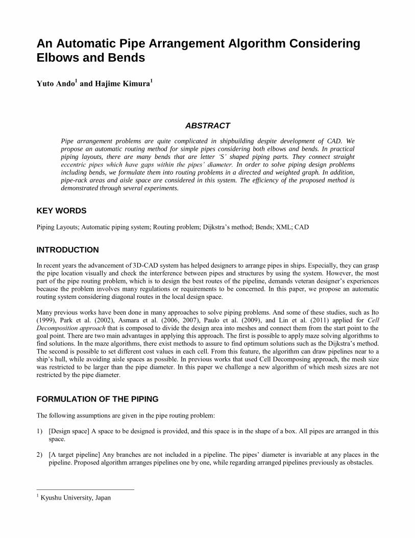
Figure 1 illustrates a simple example using the Dijkstra’s method. The start node is node S and the goal node is node G. The
route between node S and G is found by the Dijkstra’s method repeating the four steps as described. In case with n nodes and
m edges, the amount of computation with this method is O(n2) at worst, and this is the best possible complexity to solve the
routing problem in the directed and weighted graph. The proposed algorithm can find solutions efficiently from this merit.
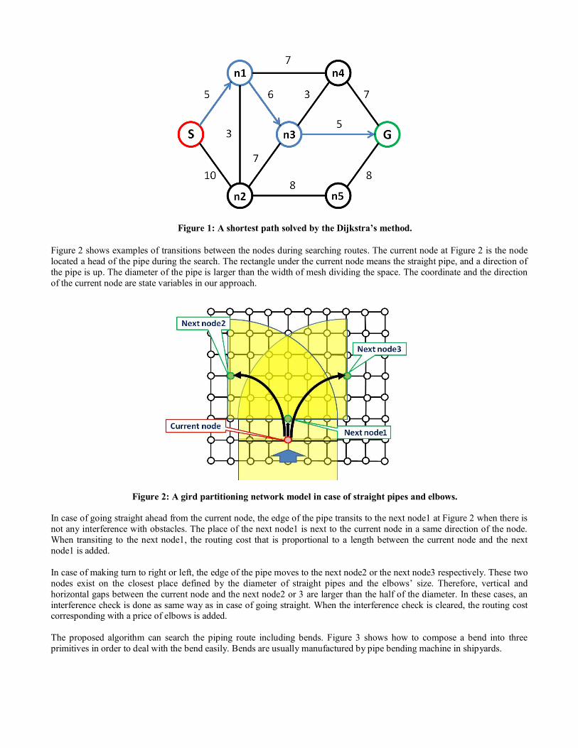
Figure 1: A shortest path solved by the Dijkstra’s method.
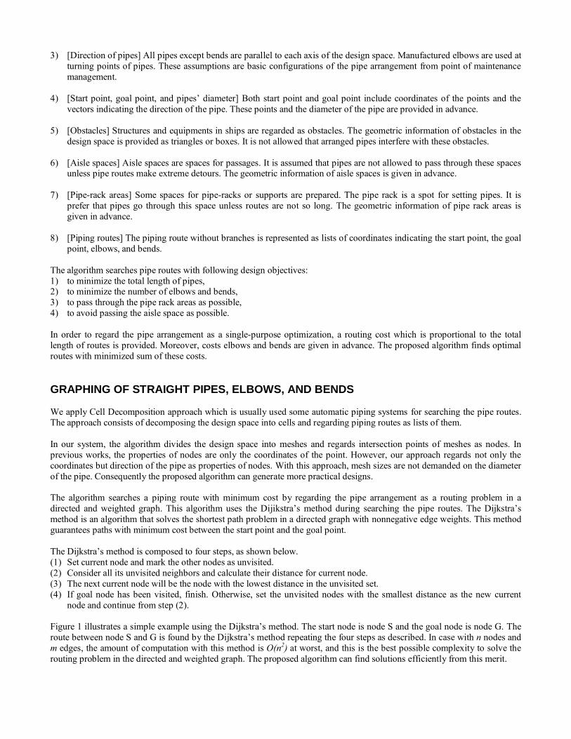
Figure 2 shows examples of transitions between the nodes during searching routes. The current node at Figure 2 is the node
located a head of the pipe during the search. The rectangle under the current node means the straight pipe, and a direction of
the pipe is up. The diameter of the pipe is larger than the width of mesh dividing the space. The coordinate and the direction
of the current node are state variables in our approach.
Figure 2: A gird partitioning network model in case of straight pipes and elbows.
In case of going straight ahead from the current node, the edge of the pipe transits to the next node1 at Figure 2 when there is
not any interference with obstacles. The place of the next node1 is next to the current node in a same direction of the node.
When transiting to the next node1, the routing cost that is proportional to a length between the current node and the next
node1 is added.
In case of making turn to right or left, the edge of the pipe moves to the next node2 or the next node3 respectively. These two
nodes exist on the closest place defined by the diameter of straight pipes and the elbows’ size. Therefore, vertical and
horizontal gaps between the current node and the next node2 or 3 are larger than the half of the diameter. In these cases, an
interference check is done as same way as in case of going straight. When the interference check is cleared, the routing cost corresponding with a price of elbows is added.
The proposed algorithm can search the piping route including bends. Figure 3 shows how to compose a bend into three
primitives in order to deal with the bend easily. Bends are usually manufactured by pipe bending machine in shipyards.
Figure 3: A bend part composed of three primitives.
The degrees of bending can be given by
2222112
12arcsin
112
12arcsin
Rd [1]
where d is the horizontal gaps between the current point and the next point, R is the radius of the bend, α1 is the coefficient of
the bending radius, and α2 is the coefficient of the straight part. The α1 and α2 express constraint condition of the pipe
bending machine that makes the bends. Numerical values of d, R, α1, and α2 are given in advance.
The minimum vertical length of the bend is computed by
cos2sin12 RRL [2]
where β is the value calculated through equation [1]. In our experiments, the value of α1 and α2 are set to 5, 0, respectively,
and the value of d is limited in the diameter of the pipe.
In case of searching the next node through the bend, the algorithm searches nodes which exist in the place away from the
length L calculated through equation [2]. From these nodes, the algorithm chooses the closest node as the next node.
Figure 4 shows an example of a node transition by using a bend. In Figure 4, the current node is the node located a head of
the pipe during search, and the diameter of the pipe is larger than the size of meshes constructing the design area.
In case of using the bend which links the current node and the next node, the algorithm will search the temporary node as
shown in Figure 4. The length between the current node and the temporary node is larger than the pipe diameter. Once the
temporary node is found, the algorithm searches the next node as shown in Figure 4. The next node is placed farther than the
L calculated through equation (2) from the temporary node.
In this case, the interference check is done as the same way as in other cases, and the current node links with the next node if
the check will be cleared. This new link includes the cost of the bend which corresponds with a price of it.
The algorithm searches piping routes from start point while repeating these processes at all linked nodes. The algorithm is
able to search the route without restriction of mesh sizes because of calculating a distance between the current node and the
next node at each time.
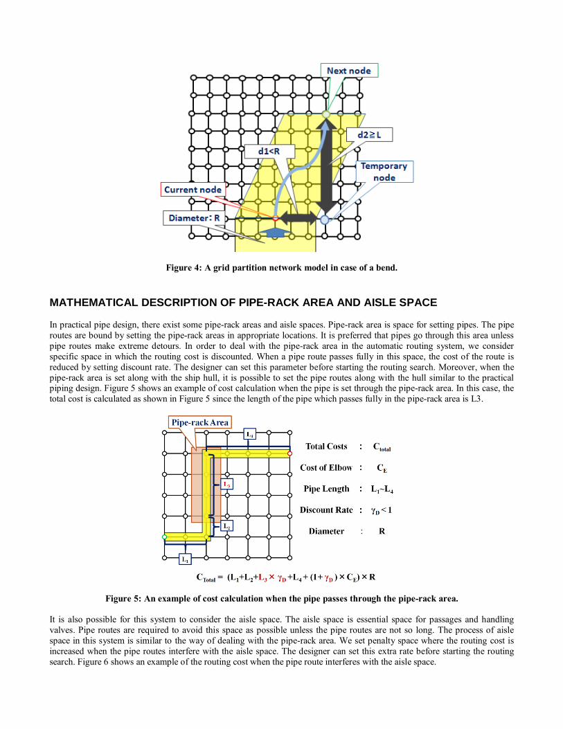
Figure 4: A grid partition network model in case of a bend.
MATHEMATICAL DESCRIPTION OF PIPE-RACK AREA AND AISLE SPACE
In practical pipe design, there exist some pipe-rack areas and aisle spaces. Pipe-rack area is space for setting pipes. The pipe
routes are bound by setting the pipe-rack areas in appropriate locations. It is preferred that pipes go through this area unless
pipe routes make extreme detours. In order to deal with the pipe-rack area in the automatic routing system, we consider
specific space in which the routing cost is discounted. When a pipe route passes fully in this space, the cost of the route is
reduced by setting discount rate. The designer can set this parameter before starting the routing search. Moreover, when the
pipe-rack area is set along with the ship hull, it is possible to set the pipe routes along with the hull similar to the practical piping design. Figure 5 shows an example of cost calculation when the pipe is set through the pipe-rack area. In this case, the
total cost is calculated as shown in Figure 5 since the length of the pipe which passes fully in the pipe-rack area is L3.
Figure 5: An example of cost calculation when the pipe passes through the pipe-rack area.
It is also possible for this system to consider the aisle space. The aisle space is essential space for passages and handling
valves. Pipe routes are required to avoid this space as possible unless the pipe routes are not so long. The process of aisle
space in this system is similar to the way of dealing with the pipe-rack area. We set penalty space where the routing cost is
increased when the pipe routes interfere with the aisle space. The designer can set this extra rate before starting the routing
search. Figure 6 shows an example of the routing cost when the pipe route interferes with the aisle space.
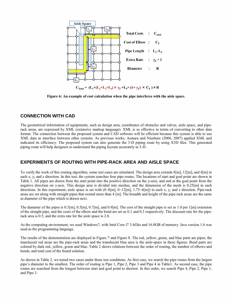
Figure 6: An example of cost calculation when the pipe interferes with the aisle space.
CONNECTION WITH CAD
The geometrical information of equipments, such as design area, coordinates of obstacles and valves, aisle space, and pipe-
rack areas, are expressed by XML (extensive markup language). XML is so effective in terms of converting to other data
format. The connection between the proposed system and CAD software will be efficient because this system is able to use
XML data as interface between other systems. As previous works, Asmara and Nienhuis (2006, 2007) applied XML and
indicated its efficiency. The proposed system can also generate the 3-D piping route by using X3D files. This generated
piping route will help designers to understand the piping layouts accurately in 3-D.
EXPERIMENTS OF ROUTING WITH PIPE-RACK AREA AND AISLE SPACE To verify the work of this routing algorithm, some test cases are simulated. The design area extends 8[m], 12[m], and 4[m] in
each x, y, and z direction. In this test, the system searches four pipe routes. The locations of start and goal point are shown in
Table 1. All pipes are drawn from the start point into the positive direction on the y-axis, and end at the goal point from the
negative direction on y-axis. This design area is divided into meshes, and the dimension of the mesh is 0.25[m] in each
directions. In this experiment, aisle space is set with (0~8[m], 0~12[m], 1.75~4[m]) in each x, y, and z direction. Pipe-rack
areas are set along with straight pipes that extend more than 4 [m]. The breadth and height of the pipe-rack areas are the same
as diameter of the pipe which is drawn next.
The diameter of the pipes is 0.3[m], 0.5[m], 0.7[m], and 0.9[m]. The cost of the straight pipe is set as 1.0 per 1[m] extension
of the straight pipe, and the costs of the elbow and the bend are set as 0.1 and 0.3 respectively. The discount rate for the pipe-
rack area is 0.5, and the extra rate for the aisle space is 2.0.
As the computing environment, we used Windows7, with Intel Core i7 3.4Ghz and 16.0GB of memory. Java version 1.6 was
used as the programming language.
The results of the demonstration are displayed in Figure 7 and Figure 8. The red, yellow, green, and blue parts are pipes, the
translucent red areas are the pipe-rack areas and the translucent blue area is the aisle-space in these figures. Bend parts are
colored by dark red, yellow, green and blue. Table 2 shows relations between the order of routing, the number of elbows and
bends, and total cost of the found solution.
As shown in Table 2, we tested two cases under these test conditions. As first case, we search the pipe routes from the largest
pipe’s diameter to the smallest. The order of routing is Pipe 1, Pipe 2, Pipe 3 and Pipe 4 in Table1. As second case, the pipe
routes are searched from the longest between start and goal point to shortest. In this order, we search Pipe 4, Pipe 2, Pipe 1, and Pipe 3.
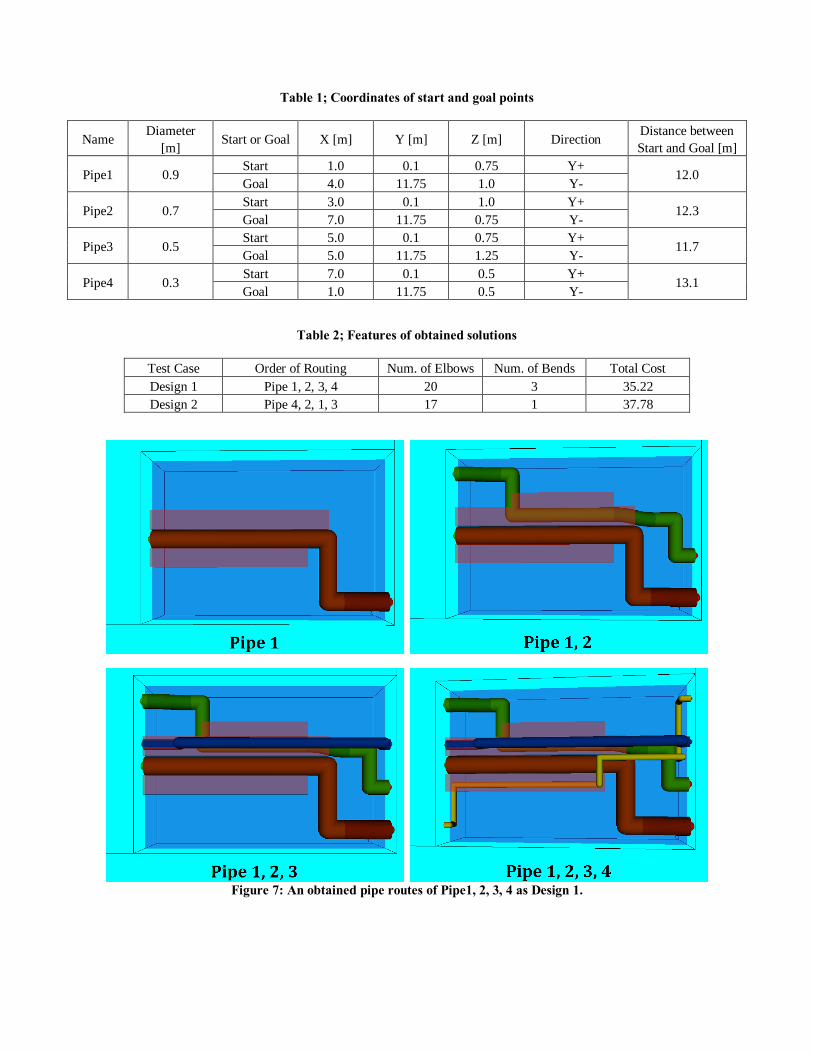
Table 1; Coordinates of start and goal points
Name Diameter
[m] Start or Goal X [m] Y [m] Z [m] Direction
Distance between
Start and Goal [m]
Pipe1 0.9 Start 1.0 0.1 0.75 Y+
12.0 Goal 4.0 11.75 1.0 Y-
Pipe2 0.7 Start 3.0 0.1 1.0 Y+
12.3 Goal 7.0 11.75 0.75 Y-
Pipe3 0.5 Start 5.0 0.1 0.75 Y+
11.7 Goal 5.0 11.75 1.25 Y-
Pipe4 0.3 Start 7.0 0.1 0.5 Y+
13.1 Goal 1.0 11.75 0.5 Y-
Table 2; Features of obtained solutions
Test Case Order of Routing Num. of Elbows Num. of Bends Total Cost
Design 1 Pipe 1, 2, 3, 4 20 3 35.22
Design 2 Pipe 4, 2, 1, 3 17 1 37.78
Figure 7: An obtained pipe routes of Pipe1, 2, 3, 4 as Design 1.
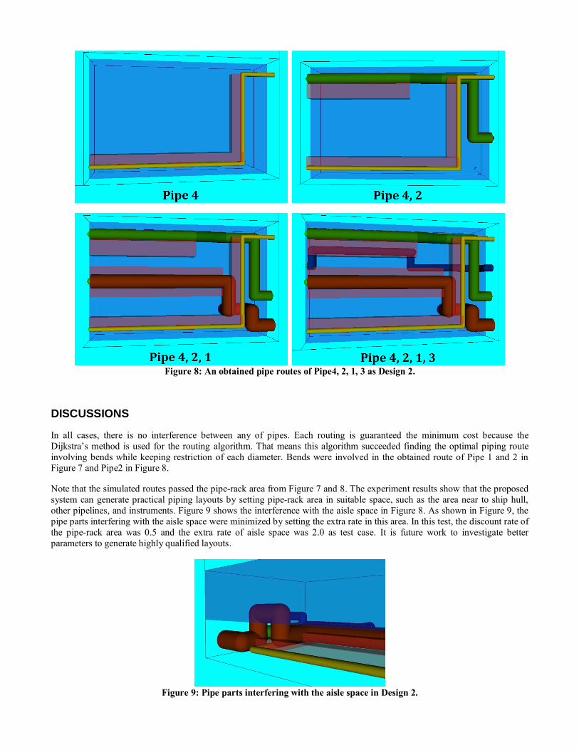
Figure 8: An obtained pipe routes of Pipe4, 2, 1, 3 as Design 2.
DISCUSSIONS
In all cases, there is no interference between any of pipes. Each routing is guaranteed the minimum cost because the
Dijkstra’s method is used for the routing algorithm. That means this algorithm succeeded finding the optimal piping route
involving bends while keeping restriction of each diameter. Bends were involved in the obtained route of Pipe 1 and 2 in
Figure 7 and Pipe2 in Figure 8.
Note that the simulated routes passed the pipe-rack area from Figure 7 and 8. The experiment results show that the proposed
system can generate practical piping layouts by setting pipe-rack area in suitable space, such as the area near to ship hull,
other pipelines, and instruments. Figure 9 shows the interference with the aisle space in Figure 8. As shown in Figure 9, the
pipe parts interfering with the aisle space were minimized by setting the extra rate in this area. In this test, the discount rate of
the pipe-rack area was 0.5 and the extra rate of aisle space was 2.0 as test case. It is future work to investigate better
parameters to generate highly qualified layouts.
Figure 9: Pipe parts interfering with the aisle space in Design 2.
Comparing Figure 7 and 8, the final design of pipe routes is changed by the order of drawing pipes. This automatic routing
system searches the pipe routes one by one. Therefore the final design is very dependent on the order of drawing. As shown
in Table 2, the total cost of Design 1 is lower than the cost of Design 2. In addition, the pipe routes of Design 1 are
concentrated and set in the same direction in middle of the design area. Accordingly, the pipe routes of Design 1 are
considered to be easy to construct in the context of practical design. Because of these points, the order 1(Pipe 1, 2, 3, 4) that
is from largest diameter to the smallest is more suitable for this test condition than the order 2 (Pipe 4, 2, 1, 3) that is the
longest distance between start and goal point to the shortest. In actual design of pipe arrangement, designers usually decide
pipe routes from the largest one to the smallest. Considering this aspect, we regard that the order 1 is appropriate order.
However, further simulation is needed to decide the best order of routing.
In this simulation, notice that the decrease of the diameter caused the increase of the searching time. An improvement of the
algorithm can prevent the increase of searching time. The Dijkstra’s method is classed as the breadth-first search. However
this searching style needs huge memories to find solutions because this method searches all neighbor nodes from the searched
node. We will use the A* search which is improved version of the Dijkstra’s method as our future work.
DISCUSSION ABOUT THE OTHER TEST CASE
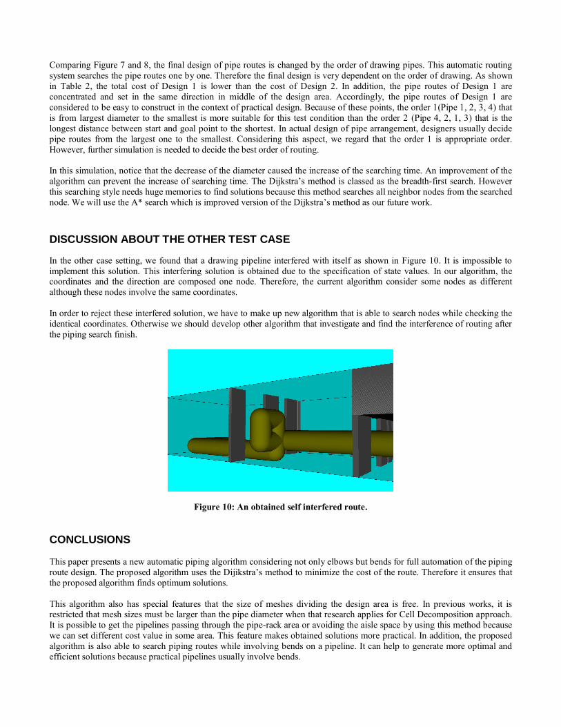
In the other case setting, we found that a drawing pipeline interfered with itself as shown in Figure 10. It is impossible to
implement this solution. This interfering solution is obtained due to the specification of state values. In our algorithm, the coordinates and the direction are composed one node. Therefore, the current algorithm consider some nodes as different
although these nodes involve the same coordinates.
In order to reject these interfered solution, we have to make up new algorithm that is able to search nodes while checking the
identical coordinates. Otherwise we should develop other algorithm that investigate and find the interference of routing after
the piping search finish.
Figure 10: An obtained self interfered route.
CONCLUSIONS
This paper presents a new automatic piping algorithm considering not only elbows but bends for full automation of the piping
route design. The proposed algorithm uses the Dijikstra’s method to minimize the cost of the route. Therefore it ensures that
the proposed algorithm finds optimum solutions.
This algorithm also has special features that the size of meshes dividing the design area is free. In previous works, it is restricted that mesh sizes must be larger than the pipe diameter when that research applies for Cell Decomposition approach.
It is possible to get the pipelines passing through the pipe-rack area or avoiding the aisle space by using this method because
we can set different cost value in some area. This feature makes obtained solutions more practical. In addition, the proposed
algorithm is also able to search piping routes while involving bends on a pipeline. It can help to generate more optimal and
efficient solutions because practical pipelines usually involve bends.

This automatic routing system can consider pipe-rack areas and aisle space by setting the discount or the extra rate in each
area. In consequence the obtained pipe routes are near to each other and the several pipes are able to use the same supports by
setting the pipe-rack areas. Setting the aisle space can balance an easiness of passage with total cost of pipes.
In order to improve the algorithm, we revolve about the many practical aspects of the piping routes such as searching time,
the order of pipes to set, and constraints of piping constructions.
ACKNOWLEDGEMENTS
This paper is the result of work sponsored by Japan Society for the Promotion of Science (JSPS) Grants-in-Aid for Scientific
Research (B) 23360388. This support is gratefully acknowledged.
REFERENCES W. CHEN., “Gaprus-Genetic Algorithm Based Pipe Routing Using Tessellated Objects”, Journal of Computers in Industry,
1998.
S. IKEHIRA, H. KAJIWAEA, and H. KIMURA, “Automatic Design for Pipe Arrangement using Multi-objective Genetic
Algorithm”, International Conference on Computer Applications in Shipbuilding (ICCAS), 2005.
H. KIMURA, and S. IKEHIRA, “Automatic Design for Pipe Arrangement Considering Valve Operability”, International
Conference on Computer Applications in Shipbuilding (ICCAS), 2009.
T. ITO and S. FUKUDA, “A genetic algorithm approach to piping route path planning”, Journal of Intelligent Manufacturing,
1999.
J. H. PARK, and R. L. STORCH, “Pipe-routing Algorithm Development: Case Study of a Ship Engine Room Design”,
Journal of Expert Systems with Application, 2002.
ASMARA, A. and U. NIENHUIS, “Automatic Piping System in Ship”, International Conference on Computer and IT
Application (COMPIT), 2006.
ASMARA, A. and U. NIENHUIS, “Automatic piping system Implementation”, International Conference on Computer and
IT Application (COMPIT), 2007.
T. M. PAULO, and V. J. A. S. LOBO, “A Tool for Automatic Routing of Auxiliary Circuits in Ships”, Portuguese
Conference on Artificial Intelligence (EPIA), 2009.
Chun-Hung Lin, Li-Wei Wang, Jiun-Shiang Peng, “Engine Room Pipeline Arrangement with Consideration of Equipments
Operability Space by Genetic Algorithm”, International Conference on Computer Application in Shipbuilding (ICCAS), 2011


![[PPT]General Arrangement Plan - University of Rijeka · Web viewGeneral Arrangement Plan Lesson 2 General Arrangement Plan depicts the division and arrangement of the ship side view](https://img.pdfslide.us/doc/110x75/5af6fcf37f8b9ae9488f8007/pptgeneral-arrangement-plan-university-of-viewgeneral-arrangement-plan-lesson.jpg)