Embed Size (px)
Citation preview
*Corresponding author tel: +234-703-186-7444.
AN AUTOMATED RAILWAY STATION TRAFFIC CONTROL SYSTEM
J. A. Enokela1,* and K. L. Oladejo2 1,2 DEPT. OF ELECTRICAL AND ELECTRONICS ENGR. FED. UNIVERSITY OF AGRICULTURE, MAKURDI, BENUE STATE, NIGERIA
E-mail addresses: [email protected]; [email protected]
ABSTRACT
Majority of accidents experienced with railway transportation involve collision with automobiles or other vehicles and
collision with other trains. These collisions can be averted by putting safety measures in place. Part of the measures can
be achieved by using computerized railway station traffic control systems that use microcontrollers and
electromechanical devices to shift traffic from one rail lane to another and also to operate the level crossing gate. The two
major stages of the system being described here are thus the track switching stage and the level crossing gate stage. The
system makes use of microcontrollers for decision making. The microcontrollers are programmed to detect signals from
sensors and to output the processed signals to control electromagnetic devices through motor drivers. The codes for the
microcontrollers were written in PIC Basic programming language and were debugged and compiled using Micro Code
Studio Integrated Development Environment. The resultant Hex files were programmed into the memory of the
microcontrollers with the aid of a universal programmer. Software simulation was carried out using the Proteus virtual
system modeling software. A scaled down prototype of the system was built and tested. The prototype was able to
execute all the decisions required to control the given railway station. A practical real life system would require the
scaling up of the power required to drive the various motors; the logic of the system would however remain unchanged.
The inclusion of the automated traffic control lighting system at the level crossing gate in the system eliminates the
fatigue and tedium associated with a manually controlled traffic system. The computerized railway station traffic control
system which helps in track switching and level crossing gate traffic control is capable of improving reliability, speed,
operational safety and efficiency of the railway transportation system.
Keywords: Rail Track Switching, Microcontroller, Rail Level Crossing Gate, Traffic Control
1. INTRODUCTION
The railway transportation system provides services to
millions of passengers worldwide and is also responsible
for the haulage of tones of goods daily. It is a high
capacity system and it is economical. The necessity to
keep train journeys safe and reliable cannot be
overemphasized. A number of recent train accidents
especially train-train collisions on the tracks, and train-
vehicle collisions at the level crossings, have been
attributed to the old methods of signaling and operations
[1].The introduction of computerized railway traffic
control systems that have automatic safety features will
improve the reliability, efficiency, and safety of the
railway system both in the station and at the level
crossing.
Many attempts have been made to design such systems
that will provide a reliable safety measure to the railway.
The works discussed in [2] and [3] considered the safety
of the rail but they do not extend to safety at the level
crossing gate in terms of automatic operation of the gate.
A system that provides efficient rail safety is discussed in
[4]. The main shortcoming of this system is that it does
not extend its scope to track switching; thus it does not
give complete safety as required. The development of a
rail safety system explained in [1] shows that automatic
track switching can be performed both automatically and
manually and also can be controlled by the software from
the main control room which gives the system more
flexibility of operation. The main drawback of this work
is that it does not include the level crossing gate. In the
work done discussed in [5] the track switching and level
crossing were put into consideration to provide complete
rail safety. This work does not extend to the safety within
the train parking yard. An elaborate system that uses
onboard computer that compares the train’s location and
speed with authorized speed limits, automatically
applying the train’s brakes when necessary, is provided
by Signalling Solutions [6]. Some applications of the
Global Navigation Satellite System (GNSS) to rail traffic
are discussed in [7] and [8].
Nigerian Journal of Technology (NIJOTECH)
Vol. 36, No. 1, January 2017, pp. 138 – 147
Copyright© Faculty of Engineering, University of Nigeria, Nsukka,
Print ISSN: 0331-8443, Electronic ISSN: 2467-8821
www.nijotech.com
http://dx.doi.org/10.4314/njt.v36i1.18
AN AUTOMATED RAILWAY STATION TRAFFIC CONTROL SYSTEM J. A. Enokela & K. L. Oladejo
Nigerian Journal of Technology Vol. 36, No. 1, January, 2017 139
In this work, our designed system considered a multi-
track railway station; the process of arrival and
departure of trains to and from the station was
programmed into the memory of a microcontroller and
this program handles all traffic related matters within
the railway station. Another microcontroller was
programmed to handle traffic flow across the two level
crossings that are associated with the railway station
under study. The microcontrollers take inputs from
sensors and, after processing these signals, control
motors through relays and drivers to switch tracks and
also to operate level crossing gates. Some advantages of
our system include:
(i) The design and construction of a computerized
railway station traffic control system will ease
operation of a point or switch in the event that a
train wants to be shunted out of a lane.
(ii) It will assist in sequential parking of train and also
notify the operators when the tracks are full.
(iii) It will help in the control of level crossing gates
which will reduce, if not totally eliminate, train-
vehicle collision.
(iv) The system will help with easy shutting down of
lane(s) that require maintenance.
(v) It will assist in prevention of fatal accidents that
may be caused by train-train collision.
(vi) The system will reduce, if not eliminate, the fatigue
of railway staff at the level crossing junction to
control motorists and pedestrians in order to give
the train priority to pass at the level crossing
junction.
2. MATERIALS AND METHOD
2.1 Architecture of the System
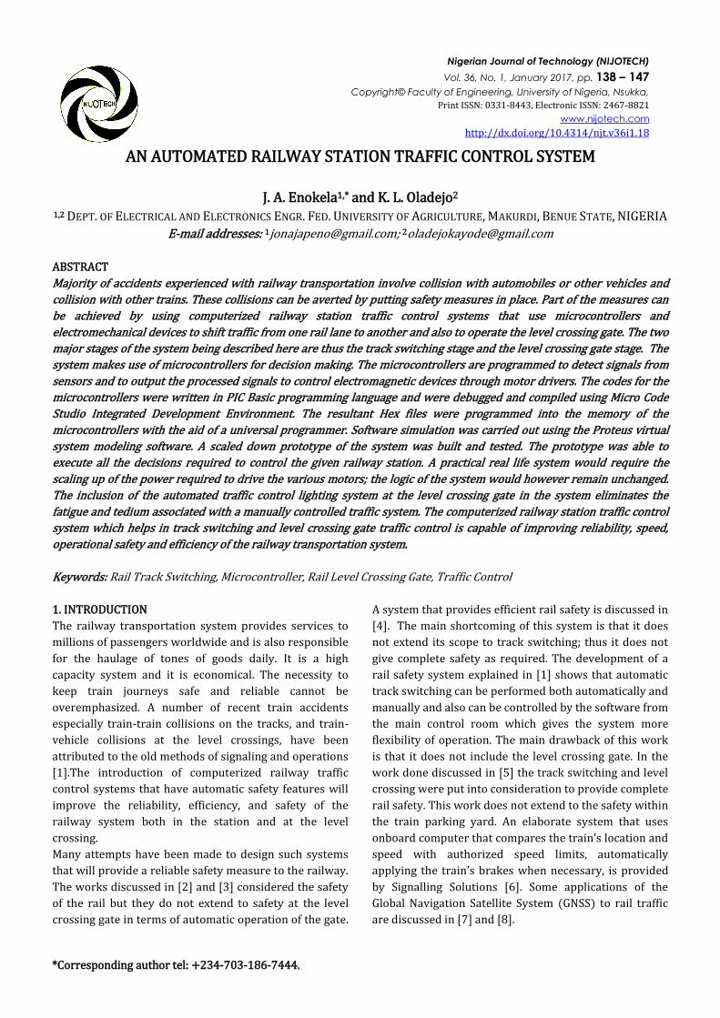
The proposed railway station traffic control system is
made up of two stages: the track switching stage and the
level crossing stage. The block diagrams of the system
are shown in figure 1. The block diagrams show that the
system is made up of three principal units. The detector
unit consists of sensors. Signalling Solutions senses the
passage of train with the aid of a specialized sensor
known as Eurobalise that is installed in the tracks [6].
Various types of sensors including infrared, strain gauge,
and laser may be used [9]. The signal processing unit is
the microcontroller itself. This unit takes inputs from the
sensors in the detector unit and sends output signals to
the control unit that consists of the motor drivers, the
motors, visual display units and the alarm system.
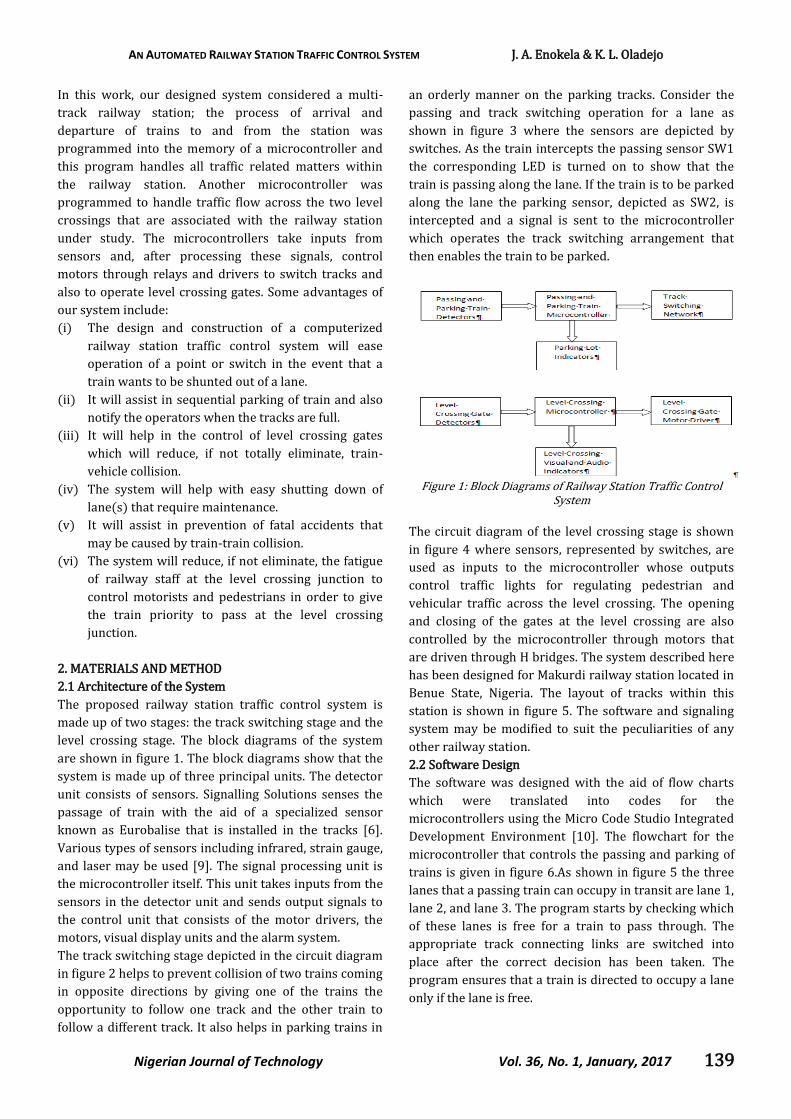
The track switching stage depicted in the circuit diagram
in figure 2 helps to prevent collision of two trains coming
in opposite directions by giving one of the trains the
opportunity to follow one track and the other train to
follow a different track. It also helps in parking trains in
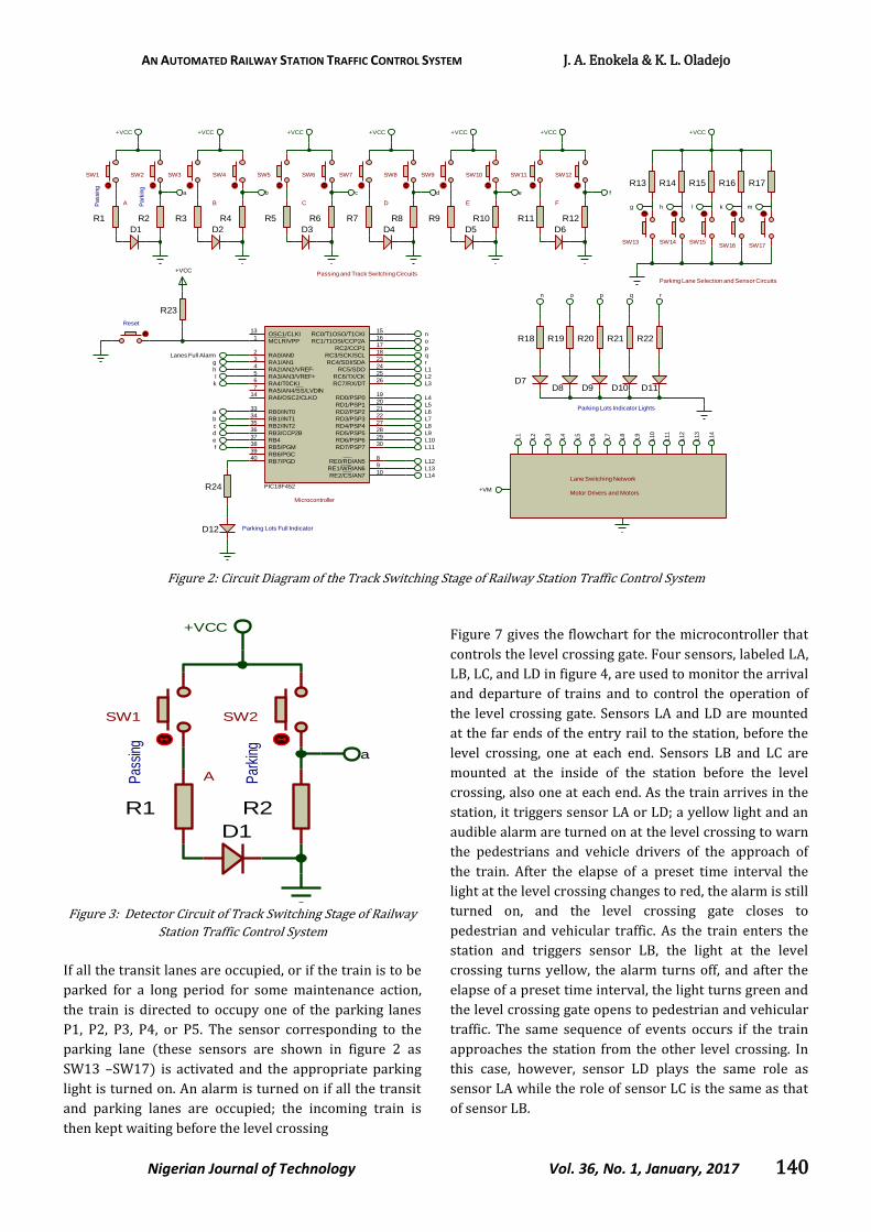
an orderly manner on the parking tracks. Consider the
passing and track switching operation for a lane as
shown in figure 3 where the sensors are depicted by
switches. As the train intercepts the passing sensor SW1
the corresponding LED is turned on to show that the
train is passing along the lane. If the train is to be parked
along the lane the parking sensor, depicted as SW2, is
intercepted and a signal is sent to the microcontroller
which operates the track switching arrangement that
then enables the train to be parked.
Figure 1: Block Diagrams of Railway Station Traffic Control
System
The circuit diagram of the level crossing stage is shown
in figure 4 where sensors, represented by switches, are
used as inputs to the microcontroller whose outputs
control traffic lights for regulating pedestrian and
vehicular traffic across the level crossing. The opening
and closing of the gates at the level crossing are also
controlled by the microcontroller through motors that
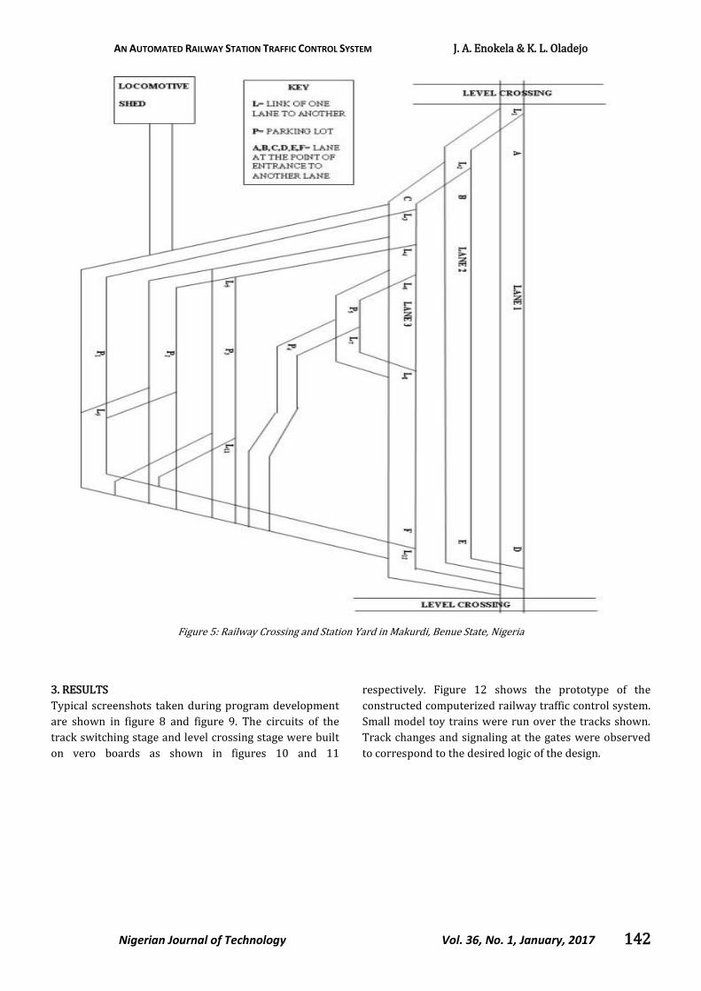
are driven through H bridges. The system described here
has been designed for Makurdi railway station located in
Benue State, Nigeria. The layout of tracks within this
station is shown in figure 5. The software and signaling
system may be modified to suit the peculiarities of any
other railway station.
2.2 Software Design
The software was designed with the aid of flow charts
which were translated into codes for the
microcontrollers using the Micro Code Studio Integrated
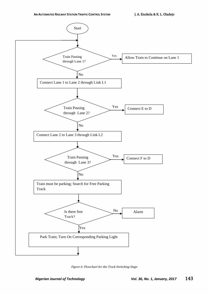
Development Environment [10]. The flowchart for the
microcontroller that controls the passing and parking of
trains is given in figure 6.As shown in figure 5 the three
lanes that a passing train can occupy in transit are lane 1,
lane 2, and lane 3. The program starts by checking which
of these lanes is free for a train to pass through. The
appropriate track connecting links are switched into
place after the correct decision has been taken. The
program ensures that a train is directed to occupy a lane
only if the lane is free.
AN AUTOMATED RAILWAY STATION TRAFFIC CONTROL SYSTEM J. A. Enokela & K. L. Oladejo
Nigerian Journal of Technology Vol. 36, No. 1, January, 2017 140
Figure 2: Circuit Diagram of the Track Switching Stage of Railway Station Traffic Control System
Figure 3: Detector Circuit of Track Switching Stage of Railway
Station Traffic Control System
If all the transit lanes are occupied, or if the train is to be
parked for a long period for some maintenance action,
the train is directed to occupy one of the parking lanes
P1, P2, P3, P4, or P5. The sensor corresponding to the
parking lane (these sensors are shown in figure 2 as
SW13 –SW17) is activated and the appropriate parking
light is turned on. An alarm is turned on if all the transit
and parking lanes are occupied; the incoming train is
then kept waiting before the level crossing
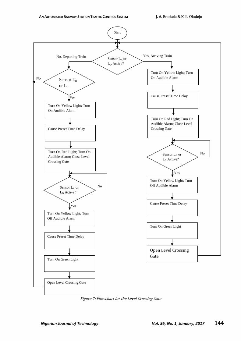
Figure 7 gives the flowchart for the microcontroller that
controls the level crossing gate. Four sensors, labeled LA,
LB, LC, and LD in figure 4, are used to monitor the arrival
and departure of trains and to control the operation of
the level crossing gate. Sensors LA and LD are mounted
at the far ends of the entry rail to the station, before the
level crossing, one at each end. Sensors LB and LC are
mounted at the inside of the station before the level
crossing, also one at each end. As the train arrives in the
station, it triggers sensor LA or LD; a yellow light and an
audible alarm are turned on at the level crossing to warn
the pedestrians and vehicle drivers of the approach of
the train. After the elapse of a preset time interval the
light at the level crossing changes to red, the alarm is still
turned on, and the level crossing gate closes to
pedestrian and vehicular traffic. As the train enters the
station and triggers sensor LB, the light at the level
crossing turns yellow, the alarm turns off, and after the
elapse of a preset time interval, the light turns green and
the level crossing gate opens to pedestrian and vehicular
traffic. The same sequence of events occurs if the train
approaches the station from the other level crossing. In
this case, however, sensor LD plays the same role as
sensor LA while the role of sensor LC is the same as that
of sensor LB.
MCLR/VPP1
RA0/AN02
RA1/AN13
RA2/AN2/VREF-4
RA3/AN3/VREF+5
RA4/T0CKI6
RA5/AN4/SS/LVDIN7
RE0/RD/AN58
RE1/WR/AN69
RE2/CS/AN710
OSC1/CLKI13
RA6/OSC2/CLKO14
RC0/T1OSO/T1CKI15
RC2/CCP117
RC3/SCK/SCL18
RD0/PSP019
RD1/PSP120
RD2/PSP221
RD3/PSP322
RD4/PSP427
RD5/PSP528
RD6/PSP629
RD7/PSP730
RC4/SDI/SDA23
RC5/SDO24
RC6/TX/CK25
RC7/RX/DT26
RB0/INT033
RB1/INT134
RB2/INT235
RB3/CCP2B36
RB437
RB5/PGM38
RB6/PGC39
RB7/PGD40
RC1/T1OSI/CCP2A16
PIC18F452
+VCC
R1 R2
a
SW1 SW2
+VCC
R3 R4
b
SW3 SW4
+VCC
R5 R6
c
SW5 SW6
+VCC
R7 R8
d
SW7 SW8
+VCC
R9 R10
e
SW9 SW10
+VCC
R11 R12
f
SW11 SW12
+VCC
Pa
ssi
ng
Pa
rkin
g
D1 D2 D3 D4 D5 D6
R13 R14 R15 R16 R17
+VCC
g h l k m
SW14 SW15SW16 SW17
SW13
R18 R19 R20 R21 R22
D7D8 D9 D10 D11
n o p q r
Parking Lots Indicator Lights
R23
Reset
R24
D12 Parking Lots Full Indicator
g
h
l
k
a
b
c
d
e
f
n
o
p
q
r
Lane Switching Network
Motor Drivers and Motors
L1
L2
L3
L4
L5
L6
L7
L8
L9
L10
L11
L12
L13
L14
L1
L2
L3
L4
L5
L6
L7
L8
L9
L10
L11
L12
L13
L14
+VM
A B C D E F
Passing and Track Switching Circuits
Parking Lane Selection and Sensor Circuits
Microcontroller
Lanes Full Alarm
R1 R2
a
SW1 SW2
+VCC
R3
Pas
sing
Par
king
D1
A

AN AUTOMATED RAILWAY STATION TRAFFIC CONTROL SYSTEM J. A. Enokela & K. L. Oladejo
Nigerian Journal of Technology Vol. 36, No. 1, January, 2017 141
If a train is leaving the station instead of arriving it, the
roles of the pair of sensors LA, LB or LC, LD are reversed
but the sequence of events, however, remains the same.
The question of determining whether a train is arriving
or leaving a station is resolved by finding out if sensors
LA and LD are triggered before sensors LB and LC
respectively or vice versa.
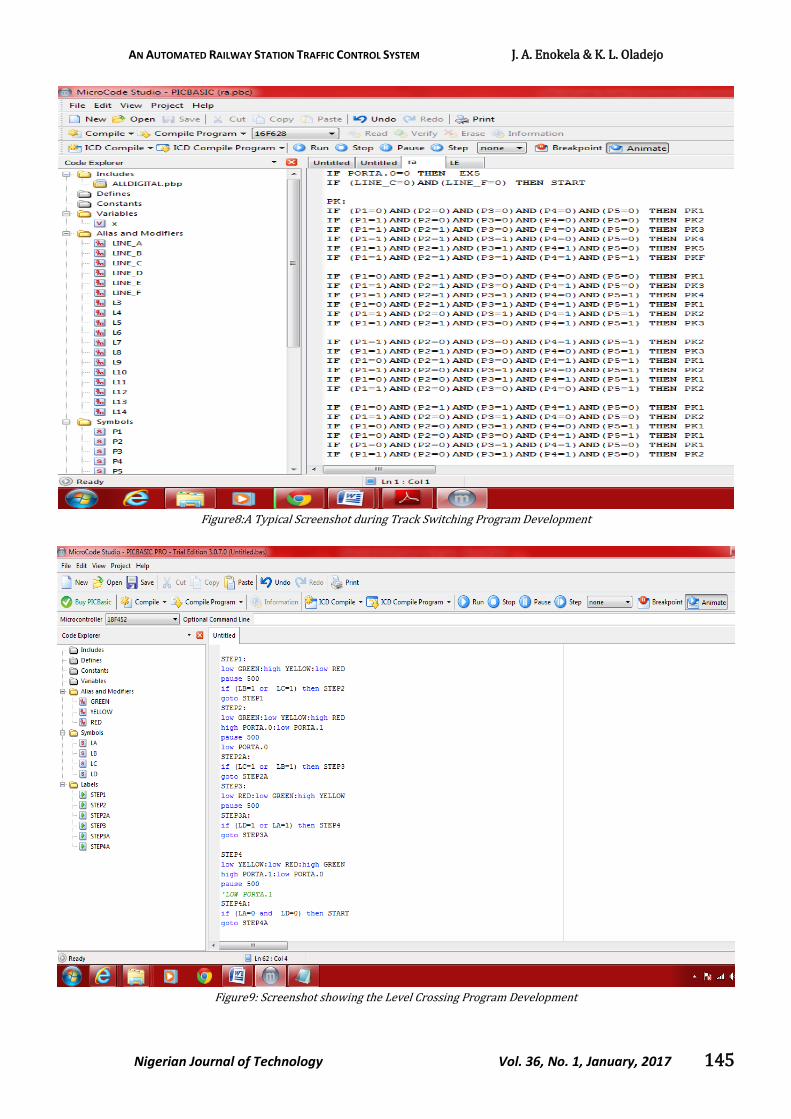
The programs for the microcontrollers were written in
PIC basic language. The programs were compiled and
debugged in the MicroCode Studio Integrated
Development Environment. The simulation of the
firmware and hardware was carried out using the
Proteus Virtual System Modeling (VSM) environment
version 8 [11]. The resultant hex file was burnt into the
program memory of the microcontroller with the aid of a
TOP2007 universal programmer [12].
Figure 4: Circuit Diagram of the Level Crossing Stage of Railway Station Traffic Control System
OSC1/CLKIN16
RB0/INT6
RB17
RB28
RB39
RB410
RB511
RB612
RB713
RA017
RA118
RA21
RA32
RA4/T0CKI3
OSC2/CLKOUT15
MCLR4
U1
PIC16F84A
R1
Q1
+VMC
D1
R2
D2
+VCC
R3
Q2
D3
R4
D4
+VCC
R5
Q3
D5
R6
D6
+VCC
R8 R9 R10
R11 R12 R13 R14
+VCC
e f g h
mk n
a
c
b
d
e
f
g
h
k
n
m
dcba
X1
C1
C2
R7
+VCC
Motor Driver
Green Yellow Red
Reset
Arrival and Departure Sensors
Level Crossing Lights
LA LB LC LD
Level Alarm 1
Level Alarm 2
AN AUTOMATED RAILWAY STATION TRAFFIC CONTROL SYSTEM J. A. Enokela & K. L. Oladejo
Nigerian Journal of Technology Vol. 36, No. 1, January, 2017 142
Figure 5: Railway Crossing and Station Yard in Makurdi, Benue State, Nigeria
3. RESULTS
Typical screenshots taken during program development
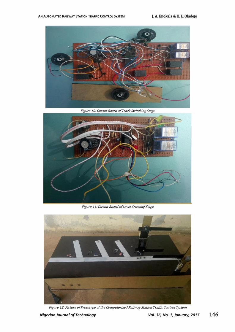
are shown in figure 8 and figure 9. The circuits of the
track switching stage and level crossing stage were built
on vero boards as shown in figures 10 and 11
respectively. Figure 12 shows the prototype of the
constructed computerized railway traffic control system.
Small model toy trains were run over the tracks shown.
Track changes and signaling at the gates were observed
to correspond to the desired logic of the design.
AN AUTOMATED RAILWAY STATION TRAFFIC CONTROL SYSTEM J. A. Enokela & K. L. Oladejo
Nigerian Journal of Technology Vol. 36, No. 1, January, 2017 143
Figure 6: Flowchart for the Track Switching Stage
Start
Train Passing
through Lane 2?
Connect E to D Yes
Train must be parking; Search for Free Parking
Track
Is there free
Track?
Alarm No
Connect Lane 1 to Lane 2 through Link L1
Park Train; Turn On Corresponding Parking Light
Connect Lane 2 to Lane 3 through Link L2
No
No
Yes
Train Passing
through Lane 1? Allow Train to Continue on Lane 1
Yes
Train Passing
through Lane 3?
Connect F to D Yes
No
AN AUTOMATED RAILWAY STATION TRAFFIC CONTROL SYSTEM J. A. Enokela & K. L. Oladejo
Nigerian Journal of Technology Vol. 36, No. 1, January, 2017 144
Figure 7: Flowchart for the Level Crossing Gate
Start
No
Turn On Yellow Light; Turn
On Audible Alarm
Sensor LA or
LD Active?
Yes, Arriving Train
Turn On Red Light; Turn On
Audible Alarm; Close Level
Crossing Gate
Cause Preset Time Delay
Sensor LB or
LC Active?
Turn On Yellow Light; Turn
Off Audible Alarm
Cause Preset Time Delay
Turn On Green Light
Open Level Crossing
Gate
Sensor LB
or LC
No, Departing Train
No
Turn On Yellow Light; Turn
On Audible Alarm
Turn On Red Light; Turn On
Audible Alarm; Close Level
Crossing Gate
Cause Preset Time Delay
Sensor LA or
LD Active?
Turn On Yellow Light; Turn
Off Audible Alarm
Cause Preset Time Delay
Turn On Green Light
Open Level Crossing Gate
Yes
Yes
No
Yes
AN AUTOMATED RAILWAY STATION TRAFFIC CONTROL SYSTEM J. A. Enokela & K. L. Oladejo
Nigerian Journal of Technology Vol. 36, No. 1, January, 2017 145
Figure8:A Typical Screenshot during Track Switching Program Development
Figure9: Screenshot showing the Level Crossing Program Development
AN AUTOMATED RAILWAY STATION TRAFFIC CONTROL SYSTEM J. A. Enokela & K. L. Oladejo
Nigerian Journal of Technology Vol. 36, No. 1, January, 2017 146
Figure 10: Circuit Board of Track Switching Stage
Figure 11: Circuit Board of Level Crossing Stage
Figure 12: Picture of Prototype of the Computerized Railway Station Traffic Control System
AN AUTOMATED RAILWAY STATION TRAFFIC CONTROL SYSTEM J. A. Enokela & K. L. Oladejo
Nigerian Journal of Technology Vol. 36, No. 1, January, 2017 147
4. DISCUSSION
Two different microcontrollers have been used in this
project because of the large number of Input/Output
(I/O) pins required to drive all the peripheral devices
connected to the microcontrollers. This also inhibits the
implementation of the anticlockwise rotation of motors
at the track switching stage for returning the shifted
track to the original position after its operation. This
project can be carried out with a single microcontroller
that has the required number of I/O pins. H-bridge
drivers can also be implemented with the motors at the
track switching stage to control the return of any shifted
track. The system described in this project has been
constructed to operate a small gate at the level crossing
stage and a low weight track at the track switching stage
in order to demonstrate the workability of the design.
The actual materials can still be used with the control
system described but the driver circuitry must use
components that can handle more power required for
expected result to be realized.
5. CONCLUSION
The computerized railway station traffic control system
that has been successfully designed and built in this work
is meant to provide a reliable safety measure against
railway accident, to help in sequential parking of trains
in station yard and also to give the train priority over
road vehicle at the level crossing junction. The system
achieves a good measure of security with the aids of
microcontrollers, electric motors and micro switches
which serve as sensors. It can be modified to industrial
standard using components that can handle more power
required for expected result to be realized.
6. REFERENCES
[1] Azim, R. S., Mahmud, K., and Das, C. K., “Automatic Track Switching System with Computerized Control from the Central Monitoring Unit”, International Journal of u- and e- Service and Technology, 2014, 20(9),p.201-212. http://www.sersc.org/journals/IJUNESST/vol7_no1/18.pdf (accessed on 27/09/2014)
[2] Antoni, M., “Formal Validation Method and Tools for French Computerized Railway Interlocking System”, IJR
International Journal of Railway, 2(3),p.99-106. http://ieexplore.ieee.org>...>Computer$ Industrial Engine (accessed on 28/09/2014) 2009.
[3] Hwang, J., and Jo, H, “Hazard Identification of Railway Signaling System Using PHA and HAZOP Method”, International Journal of Automation and Power Engineering (IJAPE), 2013, 2(2),p.32-39. http://www.ijape.org/Download.aspx?ID =3468 (accessed on 27/09/2014).
[4] Banuchandar, J., Kaliraj, V., Balasubramanian, P., Deepa, S., and Thamilarasi, N., “Automated Unmanned Railway Level Crossing System”, International Journal of Modern Engineering Research (IJMER), 2012, 2(1), p.458-463. http://www.ijmer.com/papers/Vol2_issue1/BX021458463.pdf (accessed on 30/09/2014)
[5] Krishna., Yadav, S., and Nidhi., “Automatic Railway Gate Control Using Microcontroller”, Oriental Journal of Computer Science & Technology, 6(4),p.435-440. http://computerscijournal.org/dnload/.Yadav.../ojSCSV06104P435-440.pdf (accessed on 30/09/2014). 2013,
[6] Signalling Solutions Limited, Borehamwood Industrial Park, Rowley Lane, Borehamwood, Hertfordshire, WD6 5PZ, www.signallingsolutions.com
[7] Bedrich, S., and Gu, X.,“GNSS-Based Sensor Fusion for Safety-Critical Applications in Rail Traffic”, http://www.galileo-services.org/library/2.1-Bedrich.pdf (accessed on 03/04/2015)
[8] Salmi, P., and Torkkeli, M., “Inventions Utilizing Satellite Navigation Systems in the Railway Industry- An Analysis of Patenting Activity”, Journal of Technology Management and Innovation, Vol. 4, Issue 3, pp. 46-58. 2009,.
[9] Dipoppa, G., D’Alessandro, G., Semprini, R., and Tronci, E, “Integrating Automatic Verification of Safety Requirements in Railway Interlocking System Design”, The 6th IEEE International Symposium on High Assurance Systems Engineering (HASE’01), Washington, USA, October 22-24. 2001.
[10] MicroEngineering Labs Incorporation. (online),microcode studio IDE/Debugger/Simulator. Available at:www.pbp3.com/downloads/PBP_Reference manual.pdfb (Accessed on 06/10/2014) 2014.
[11] Labcenter Electronics. (online2014), Proteus Design Suite. Available at: www.labcenter.com/index.cfm (accessed on 06/10/2014).
[12] Universal Programmer. (online2014),Universal Programmer Model: TOP 2005. Available at: http://www.nskelectronics.com/files/top_2007_spec.pdf (accessed on 04/10/2014).