Embed Size (px)
Citation preview
Journal of the Mechanics and Physics of Solids52 (2004) 977–998
www.elsevier.com/locate/jmps
An atomistic-based continuum theory for carbonnanotubes: analysis of fracture nucleation
P. Zhanga, H. Jianga, Y. Huanga ;∗, P.H. Geubelleb, K.C. HwangcaDepartment of Mechanical and Industrial Engineering, University of Illinois, 1206 W. Green Street,
Urbana, IL 61801, USAbDepartment of Aeronautical and Astronautical Engineering, University of Illinois,
Urbana, IL 61801, USAcDepartment of Engineering Mechanics, Tsinghua University, Beijing 100084, China
Received 4 June 2003; accepted 25 September 2003
Abstract
Carbon nanotubes (CNTs) display unique properties and have many potential applications.Prior theoretical studies on CNTs are based on atomistic models such as empirical poten-tial molecular dynamics (MD), tight-binding methods, or 8rst-principles calculations. Here wedevelop an atomistic-based continuum theory for CNTs. The interatomic potential is directlyincorporated into the continuum analysis through constitutive models. Such an approach in-volves no additional parameter 8tting beyond those introduced in the interatomic potential. Theatomistic-based continuum theory is then applied to study fracture nucleation in CNTs by mod-elling it as a bifurcation problem. The results agree well with the MD simulations.? 2003 Elsevier Ltd. All rights reserved.
Keywords: Carbon nanotube; Continuum analysis; Interatomic potential
1. Introduction
There has been extensive research on carbon nanotubes (CNTs) since their 8rst dis-covery (Iijima, 1991; Ebbesen and Ajayan, 1992) and the establishment of e>ectivesynthesis techniques (Thess et al., 1996). A single-wall CNT is a cylinder of graphenewith a single layer of carbon atoms, and its diameter is on the order of 1 nm. Thereare also multi-wall CNTs that are cylinders of graphene with multiple layers of carbon
∗ Corresponding author. Tel.: +1-217-265-5072; fax: +1-217-244-6534.E-mail address: [email protected] (Y. Huang).
0022-5096/$ - see front matter ? 2003 Elsevier Ltd. All rights reserved.doi:10.1016/j.jmps.2003.09.032
978 P. Zhang et al. / J. Mech. Phys. Solids 52 (2004) 977–998
0
1
2
3
4 Thermal Vibration Bending Tension
Multiwall Carbon Nanotubes
Single Wall Carbon Nanotubes
[9][6]
[2]
[4]
[1]
[8]
[7][5]
[4]
[3]
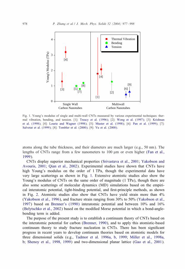
Fig. 1. Young’s modulus of single and multi-wall CNTs measured by various experimental techniques: ther-mal vibration, bending, and tension. [1]: Treacy et al. (1996); [2]: Wong et al. (1997); [3]: Krishnanet al. (1998); [4]: Lourie and Wagner (1998); [5]: Muster et al. (1998); [6]: Pan et al. (1999); [7]:Salvetat et al. (1999); [8]: Tombler et al. (2000); [9]: Yu et al. (2000).
atoms along the tube thickness, and their diameters are much larger (e.g., 50 nm). Thelengths of CNTs range from a few nanometers to 100 �m or even higher (Fan et al.,1999).CNTs display superior mechanical properties (Srivastava et al., 2001; Yakobson and
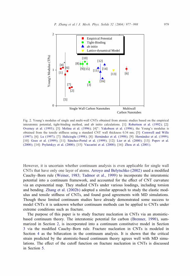
Avouris, 2001; Qian et al., 2002). Experimental studies have shown that CNTs havehigh Young’s modulus on the order of 1 TPa, though the experimental data havevery large scatterings as shown in Fig. 1. Extensive atomistic studies also show theYoung’s modulus of CNTs on the same order of magnitude (1 TPa), though there arealso some scatterings of molecular dynamics (MD) simulations based on the empiri-cal interatomic potential, tight-binding potential, and 8rst-principle methods, as shownin Fig. 2. Atomistic studies also show that CNTs have yield strain more than 4%(Yakobson et al., 1996), and fracture strain ranging from 30% to 50% (Yakobson et al.,1997) based on Brenner’s (1990) interatomic potential and between 10% and 16%(Belytschko et al., 2002) based on the modi8ed Morse potential in which a bond-angle-bending term is added.The purpose of the present study is to establish a continuum theory of CNTs based on
the interatomic potential for carbon (Brenner, 1990), and to apply this atomistic-basedcontinuum theory to study fracture nucleation in CNTs. There has been signi8cantprogress in recent years to develop continuum theories based on atomistic models forthree dimensional solids (e.g., Tadmor et al. 1996a, b, 1999; Miller et al., 1998a,b; Shenoy et al., 1998, 1999) and two-dimensional planar lattice (Gao et al., 2001).
P. Zhang et al. / J. Mech. Phys. Solids 52 (2004) 977–998 979
0
1
2
[3]
[2]
Empirical PotentialTight-Binding ab initioLattice-dynamical Model
[6]
[14]
[13]
[16]
[12]
[11][15]
[10]
[9]
[8]
[7]
[6]
[5]
[4]*
[1]
Multiwall Carbon Nanotubes
Single Wall Carbon Nanotubes
Fig. 2. Young’s modulus of single and multi-wall CNTs obtained from atomic studies based on the empiricalinteratomic potential, tight-binding method, and ab initio calculations. [1]: Robertson et al. (1992); [2]:Overney et al. (1993); [3]: Molina et al. (1996); [4]∗: Yakobson et al. (1996), the Young’s modulus isobtained from the tensile sti>ness using a standard CNT wall thickness 0:34 nm; [5]: Cornwell and Wille(1997); [6]: Lu (1997); [7]: Halicioglu (1998); [8]: HernMandez et al. (1998); [9]: HernMandez et al. (1999);[10]: Goze et al. (1999); [11]: SManchez-Portal et al. (1999); [12]: Lier et al. (2000); [13]: Popov et al.(2000); [14]: Prylutskyy et al. (2000); [15]: Vaccarini et al. (2000); [16]: Zhou et al. (2001).
However, it is uncertain whether continuum analysis is even applicable for single wallCNTs that have only one layer of atoms. Arroyo and Belytschko (2002) used a modi8edCauchy–Born rule (Weiner, 1983; Tadmor et al., 1999) to incorporate the interatomicpotential into a continuum framework, and accounted for the e>ect of CNT curvaturevia an exponential map. They studied CNTs under various loadings, including torsionand bending. Zhang et al. (2002b) adopted a similar approach to study the elastic mod-ulus and tensile sti>ness of CNTs, and found good agreements with MD simulations.Though these limited continuum studies have already demonstrated some success tomodel CNTs it is unknown whether continuum methods can be applied to CNTs underextreme conditions such as fracture.The purpose of this paper is to study fracture nucleation in CNTs via an atomistic-
based continuum theory. The interatomic potential for carbon (Brenner, 1990), sum-marized in Section 2, is incorporated into a continuum constitutive model in Section3 via the modi8ed Cauchy–Born rule. Fracture nucleation in CNTs is modeled inSection 4 as the bifurcation in the continuum analysis. It is shown that the criticalstrain predicted by the atomistic-based continuum theory agrees well with MD simu-lations. The e>ect of the cuto> function on fracture nucleation in CNTs is discussedin Section 5.

980 P. Zhang et al. / J. Mech. Phys. Solids 52 (2004) 977–998
2. An interatomic potential for carbon
Brenner (1990) established an interatomic potential for carbon from Terso> (1988)formalism as
V (rij) = VR(rij)− BijVA(rij) (1)
for atoms i and j, where rij is the distance between atoms i and j, VR and VA are therepulsive and attractive pair terms (i.e., depending only on rij) and are given by
VR(r) =D(e)
S − 1e−
√2S�(r−R(e))fc(r) ; (2)
VA(r) =D(e)SS − 1
e−√
(2=S)�(r−R(e))fc(r) ; (3)
the parameters D(e), S, �, and R(e) are determined from the known physical propertiesof carbon, graphite and diamond, and are given at the end of this section; the func-tion fc is merely a smooth cuto> function to limit the range of the potential, and isgiven by
fc(r) =
1; r ¡R(1);
12
{1 + cos
[�(r − R(1))R(2) − R(1)
]}; R(1)¡r¡R(2);
0; r ¿R(2);
(4)
which is continuous and has a cuto> of R(2) = 0:2 nm and R(1) = 0:17 nm to includeonly the 8rst-neighbor shell for carbon.The parameter Bij in Eq. (1) represents a multi-body coupling between the bond
from atom i to atom j and the local environment of atom i, and is given by
Bij =
1 + ∑
k(�=i; j)G(�ijk)fc(rik)
−�
; (5)
where k represents atoms other than i and j, rik is the distance between atoms i andk, fc is the cuto> function in Eq. (4), �ijk is the angle between bonds i–j and i–k,and the function G is given by
G(�) = a0
[1 +
c20d20
− c20d20 + (1 + cos �)2
]: (6)
For atoms i and j having di>erent local environment, Brenner (1990) suggested toreplace the coeQcient Bij in Eq. (5) by
RBij = (Bij + Bji)=2 : (7)
The parameters D(e), S, � and R(e) in Eqs. (2) and (3), � in Eq. (5), and a0, c0and d0 in Eq. (6) have been determined by Brenner (1990) to 8t the binding en-ergy and lattice constants of graphite, diamond, simple cubic and face-centered-cubic
P. Zhang et al. / J. Mech. Phys. Solids 52 (2004) 977–998 981
structures for pure carbon, as well as the vacancy formation energy for diamond andgraphite as
D(e) = 6:000 eV; S = 1:22; � = 21 nm−1; R(e) = 0:1390 nm;
�= 0:50000;
a0 = 0:00020813; c0 = 330; d0 = 3:5:
(8)
Here R(e) = 0:1390 nm represents the equilibrium bond length for a pair of carbonatoms (i.e., no other atoms such that Bij =1) and it is determined from (9=9rij) (VR −VA)|rij=R(e) = 0. For a single-wall CNT having a hexagonal lattice structure within thetube surface, the equilibrium bond length l0 is determined from
9V9rij
= 0 ; (9)
where V is the interatomic potential accounting for the multi-body coupling e>ect(i.e., Bij �= 1) in Eq. (1). The equilibrium bond length determined from Eq. (9)is l0 = 0:145 nm, which agrees well with the well-known bond length of graphite(0:144 nm).
3. An atomistic-based continuum theory for CNTs
Single-wall CNTs can be grouped to the following three categories accordingto their chiralities (the orientation of tube axis with respect to the hexagonal latticestructure):
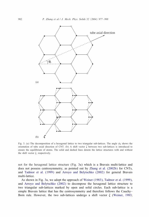
(1) armchair nanotubes where the tube axis is normal to a lattice direction, i.e., theangle between an atomic bond and the tube axis �0 = 30◦ (Fig. 3a);
(2) zigzag nanotubes where the tube axis is parallel to a lattice direction, i.e., �0 =0◦
(Fig. 3a);(3) chiral nanotubes where the tube axis is neither parallel nor normal to the lattice
directions, i.e., 0◦¡�0¡ 30◦ (Fig. 3a).
3.1. Modi:ed Cauchy–Born rule
Unlike MD simulations that keep track of the motion of every atom, the atomistic-based continuum theory developed in this section represents the collective behaviorof atoms via the constitutive model. The Cauchy–Born rule (Born and Huang, 1954;Milstein, 1980) equated the strain energy at the continuum level to the energy storedin atomic bonds. Moreover, atoms are subject to homogeneous deformation such thatthey move according to a single mapping from the undeformed to deformed con8gu-rations. Such a mapping is characterized by the continuum deformation gradient F ofa material point, where the material point represents many atoms that undergo locallyuniform deformation. For simple Bravais lattice that has the centrosymmetric atomicstructure, the Cauchy–Born rule ensures the equilibrium of atoms. However, it does
982 P. Zhang et al. / J. Mech. Phys. Solids 52 (2004) 977–998
ζζζζ
tube axial direction
φ0
(a)
(b)
Fig. 3. (a) The decomposition of a hexagonal lattice to two triangular sub-lattices. The angle �0 shows theorientation of tube axial direction of CNT. (b) A shift vector � between two sub-lattices is introduced toensure the equilibrium of atoms. The solid and dashed lines denote the lattice structures with and withoutthe shift vector �, respectively.
not for the hexagonal lattice structure (Fig. 3a) which is a Bravais multi-lattice anddoes not possess centrosymmetry, as pointed out by Zhang et al. (2002b) for CNTs,and Tadmor et al. (1999) and Arroyo and Belytschko (2002) for general Bravaismulti-lattice.As shown in Fig. 3a, we adopt the approach of Weiner (1983), Tadmor et al. (1999),
and Arroyo and Belytschko (2002) to decompose the hexagonal lattice structure totwo triangular sub-lattices marked by open and solid circles. Each sub-lattice is asimple Bravais lattice that has the centrosymmetry and therefore follows the Cauchy–Born rule. However, the two sub-lattices undergo a shift vector � (Weiner, 1983;
P. Zhang et al. / J. Mech. Phys. Solids 52 (2004) 977–998 983
Tadmor et al., 1999), as shown in Fig. 3b, which represents the relaxation of atompositions in the hexagonal lattice structure in order to minimize the energy and reach theequilibrium.Let r(0)ij = r(0)ij n
(0)ij denote the vector between two atoms i and j on the CNT prior to
deformation, r(0)ij and n(0)ij be the bond length and unit vector, respectively. For atomsi and j within the same sub-lattice, the vector rij after the deformation becomes
rij = F · r(0)ij ; (10)
and its length is
rij(E) =√rij · rij = r(0)ij
√1 + 2n(0)ij · E · n(0)ij ; (11)
where E= 12(F
T ·F − I) is the Lagrangian strain. For atoms i and j from two di>erentsub-lattices, the vector rij after the deformation also depends on the shift vector �between the two sub-lattices, and is given by
rij = F · r(0)ij + �= r(0)ij F · (n(0)ij + �) ; (12)
where � = (1=r(0)ij )F−1 · � is an internal degree of freedom which is equivalent to theshift vector �. The bond length becomes
rij(E ; �) =√rij · rij = r(0)ij
√(n(0)ij + �) · (I + 2E) · (n(0)ij + �) ; (13)
which depends on both E and �.
3.2. Continuum strain energy density
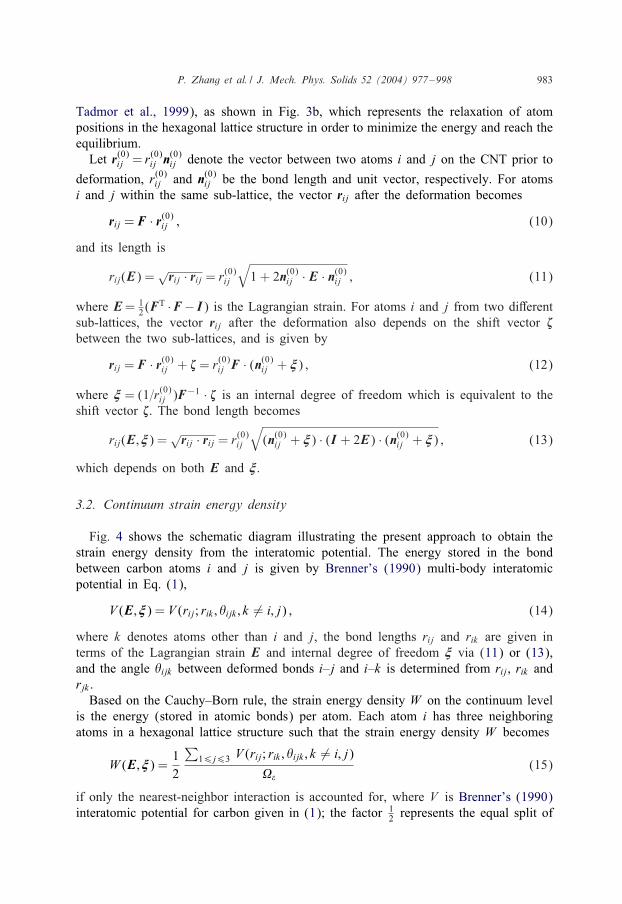
Fig. 4 shows the schematic diagram illustrating the present approach to obtain thestrain energy density from the interatomic potential. The energy stored in the bondbetween carbon atoms i and j is given by Brenner’s (1990) multi-body interatomicpotential in Eq. (1),
V (E ; �) = V (rij; rik ; �ijk ; k �= i; j) ; (14)
where k denotes atoms other than i and j, the bond lengths rij and rik are given interms of the Lagrangian strain E and internal degree of freedom � via (11) or (13),and the angle �ijk between deformed bonds i–j and i–k is determined from rij, rik andrjk .Based on the Cauchy–Born rule, the strain energy density W on the continuum level
is the energy (stored in atomic bonds) per atom. Each atom i has three neighboringatoms in a hexagonal lattice structure such that the strain energy density W becomes
W (E ; �) = 12
∑16j63 V (rij; rik ; �ijk ; k �= i; j)
��(15)
if only the nearest-neighbor interaction is accounted for, where V is Brenner’s (1990)interatomic potential for carbon given in (1); the factor 1
2 represents the equal split of
984 P. Zhang et al. / J. Mech. Phys. Solids 52 (2004) 977–998
r r
V(r) V’(r)
Deformation gradient F Lagrangian strain EDeformed bond length
),(rr ξE=
Interatomic potential),(V),r,r(V θijkikij ξE=
Strain energy density
cellofvolume
),(V),(W
Σ= ξ ξ EE
Energy minimization
0W =∂∂
ξ
Internal degree of freedom ξ = ξ (E)
Strain energy densityW [E,ξ(E)]W (E) =
Fig. 4. A schematic diagram to link the continuum analysis to the interatomic potential for CNTs possessingno centrosymmetric atomic structure.
bond energy between two atoms in each pair;
�� =3√3
4l20t0 (16)
is the average volume per atom, l0 is the unstretched bond length for the hexagonallattice structure in Fig. 3b and its value is reported at the end of Section 2; t0 is the“tube thickness” which is not well de8ned for single wall CNTs but it does not enterthe continuum analysis, as shown in the next section.
3.3. The limit of graphene
Goze et al. (1999) used tight-binding method to investigate the e>ect of nanotuberadius R on the Young’s modulus of CNTs, and showed that, for R¿ 0:4 nm, theYoung’s modulus is essentially independent of the CNT radius. Jiang et al. (2003)also showed that the CNT radius has essentially no e>ect on the Young’s modulusnor on the load-deVation curve of CNTs under tension or torsion. In the limit of largeCNT radius, a CNT becomes a graphene, i.e., a planar sheet of carbon atoms. Thesummation over three atomic bonds in Eq. (15) then becomes the summation over
P. Zhang et al. / J. Mech. Phys. Solids 52 (2004) 977–998 985
three bond orientations within the graphene plane, �0 and �0 ± 120◦, i.e.,
W (E ; �) = 12��
∑�0 ;�0±120◦
V (rij; rik ; �ijk ; k �= i; j) ; (17)
where �0 is the angle between the bond and the tube axis. In other words, (17) is thelimit of Eq. (15) without accounting for the e>ect of CNT radius.
3.4. The shift vector �
The shift vector � introduced in Section 3.1 (Fig. 3) relaxes the atom positions toensure the equilibrium of atoms. For a given Lagrangian strain E, the shift vector �or its equivalence, the internal degree of freedom �, is determined by minimizing thestrain energy density W with respect to � (Weiner, 1983; Tadmor et al., 1999; Arroyoand Belytschko, 2002; Zhang et al., 2002b), i.e.,
9W9� = 0 : (18)
Eq. (18) is a nonlinear and implicit equation that is solved numerically to determine� in terms of E, i.e.,
� = �(E) : (19)
The strain energy density in Eqs. (15) or (17) can then be written as W =W [E ; �(E)].It is straightforward to verify that � = 0 if E = 0 (i.e., no deformation).
3.5. Stress and incremental modulus
The second Piola–Kirchho> stress T is obtained from the total derivative D of strainenergy density W with respect to the Lagrangian strain E,
T =DWDE
=9W9E +
9W9� · d�
dE=9W9E ; (20)
where 9W=9�=0 in Eq. (18) has been used. Eq. (20) gives the second Piola–Kirchho>stress T in terms of the Lagrangian strain E, therefore provides the constitutive relationof single wall CNTs based on the interatomic potential V .The stress increment T is related to the strain increment E via the incremental
modulus tensor C ,
T = C : E ; (21)
where C is the total derivative of T with respect to E, and from Eq. (20)
C =DTDE
=DDE
(9W9E
)=92W9E9E − 92W
9E9� ·(92W9�9�
)−1
· 92W9�9E ; (22)
986 P. Zhang et al. / J. Mech. Phys. Solids 52 (2004) 977–998
which possesses the symmetry Cijkl = Cjikl = Cijlk = Cklij, where we have use
d�dE
=−(92W9�9�
)−1
·(92W9�9E
)
obtained from the derivative of 9W=9� = 0 in Eq. (18).
3.6. Equilibrium equation
The equilibrium equation is
(F · T) ·∇= 0 ; (23)
where ∇ is the gradient in the reference (undeformed) con8guration. In the cylindri-cal coordinates (R; �; Z) for the CNT, ∇ = eR(9=9R) + (e�=R)(9=9�) + eZ(9=9Z), theequilibrium equation (23) takes the form
99R (F · T)RR + (F · T)RR − (F · T)��
R+
1R99� (F · T)R� + 9
9Z (F · T)RZ = 0 ;
(24a)
99R (F · T)�R + (F · T)R� + (F · T)�R
R+
1R99� (F · T)�� + 9
9Z (F · T)�Z = 0 ;
(24b)
99R (F · T)ZR + (F · T)ZR
R+
1R99� (F · T)Z� + 9
9Z (F · T)ZZ = 0 : (24c)
The traction-free boundary condition can be written as
(F · T) ·N = 0 ; (25)
where N is the unit normal to the surface in the reference con8guration. It should bepointed out that Eq. (25) has not accounted for the surface stress e>ect on the boundaryconditions. If such an e>ect is accounted for, we will need to use the continuumformulation including the surface stress, such as Gurtin and Murdoch (1975). On theinner and outer surfaces of the CNT, the traction-free condition becomes
F · T · eR = 0 ; (26)
where eR is the unit vector in the radial direction prior to deformation. Since the singlewall CNT is very thin (a single layer of atoms), F ·T · eR should vanish in the entireCNT, which leads to T ·eR=0 in the CNT. Therefore, the three-dimensional equilibriumequation (24) becomes
1R99� (FR"T"�)−
1RF�"T"� +
99Z (FR"T"Z) = 0 ; (27a)
1RFR"T"� +
1R99� (F�"T"�) +
99Z (F�"T"Z) = 0 ; (27b)
1R99� (FZ"T"�) +
99Z (FZ"T"Z) = 0 ; (27c)
P. Zhang et al. / J. Mech. Phys. Solids 52 (2004) 977–998 987
where R is the nanotube radius; and the summation for " is over � and Z . Eq. (27)gives three partial di>erential equations (with respect to � and Z) for UR, U�, and UZ ,and unlike Eq. (24), they do not involve 9=9R.
4. Fracture nucleation in single-wall CNTs
Similar to the large scattering in the Young’s modulus shown in Figs. 1 and 2,the limited studies on fracture of CNTs also displayed large discrepancies in the frac-ture strain. For example, the atomistic studies of a single wall CNT under tensionbased on Brenner’s (1990) empirical interatomic potential suggested the fracture strainbetween 25% and 55% (Yakobson et al., 1997), while Yu et al.’s (2000) experimen-tal studies reported the fracture strain of multiwall CNTs between 2% and 13%. Therecent atomistic studies of Belytschko et al. (2002) based on a di>erent empirical in-teratomic potential (the modi8ed Morse potential) predicted fracture strain from 10%to 16%. It is important to note that many factors may contribute to these discrep-ancies, such as single wall CNTs under simple tension in atomic studies (Yakobsonet al., 1997) versus multi-wall CNTs subject to tension with possible bending in ex-periments (Yu et al., 2000). The di>erent empirical interatomic potentials, such asBrenner’s (1990) potential used by Yakobson et al. (1997) versus modi8ed Morse po-tential used by Belytschko et al. (2002), may also lead to signi8cantly di>erent fracturestrains.The purpose of this paper is not to evaluate the above work on fracture of CNTs.
Instead, it is to investigate whether the proposed atomistic-based continuum theorycan be used to study fracture nucleation in CNTs, and whether its results agree withthe atomistic studies based on the same interatomic potential without any parameter8tting.Yakobson et al. (1997) studied a single-wall CNT under tension using MD simu-
lations with Brenner’s (1990) empirical interatomic potential for carbon. They foundthat there exists a breaking strain �b prior to which the CNT undergoes uniform defor-mation. Once the breaking strain is reached, one or few atomic bonds break and thisatomic disorder rapidly propagates in the circumferential direction to form a neckedband which eventually leads to fracture of the CNT. The breaking strain has a largevariation from 25% to 55%. Zhang et al. (2002a) conducted an approximate analysis offracture nucleation in CNTs, and several critical assumptions were made, including (i)neglecting the multi-body coupling e>ect by taking Bij =1 in the interatomic potential(1); (ii) approximating the three atomic bonds at each atom by uniformly distributedbonds over all orientations within the tube surface and therefore not accounting forthe e>ect of the shift vector. These assumptions, in fact, do not strictly hold for singlewall CNTs.We study the breaking strain of CNTs via the atomistic-based continuum theory in
the previous section established from Brenner’s (1990) empirical interatomic potential.Instead of modelling the breaking of individual atomic bonds as in Yakobson et al.’s(1997) MD simulations, the continuum analysis focuses on the overall, “macroscopic”characteristics associated with the breaking strain. Since the CNT undergoes uniform
988 P. Zhang et al. / J. Mech. Phys. Solids 52 (2004) 977–998
deformation prior to the 8rst bond breaking in Yakobson et al.’s (1997) MD simula-tions, and nonuniform deformation only steps in after the bond breaking, fracture nucle-ation in CNTs under tension is modeled as a bifurcation in the present atomistic-basedcontinuum theory.
4.1. Armchair and zigzag CNTs
4.1.1. Pre-bifurcation: uniform deformationThe deformation in armchair and zigzag CNTs under tension is uniform and ax-
isymmetric prior to bifurcation, and is characterized by the non-vanishing componentsF�� and FZZ of the deformation gradient. The non-zero components of the Lagrangianstrain are E�� = 1
2(F2�� − 1) and EZZ = 1
2(F2ZZ − 1). The internal degree of freedom
�=�(E��; EZZ) is determined from 9W=9�=0 in Eq. (18). The second Piola-Kirchho>stress T is then obtained in terms of EZZ and E�� from Eq. (20) as
0 = T�� =9W9E��
; (28)
TZZ =9W9EZZ
; (29)
where Eq. (28) results from the requirement that T�� vanishes in uniaxial tension andit is an implicit equation to determine E�� in terms of EZZ , i.e., E�� = E��(EZZ). Thenon-zero components of the incremental modulus C����, CZZZZ , C��ZZ=CZZ�� and C�Z�Z
are obtained from Eq. (22).
4.1.2. Onset of bifurcation: nonuniform increment of deformationLet U denote the displacement, which is related to the deformation gradient F by
F = I +U∇. At the onset of bifurcation, the increment of deformation is not uniformanymore. The non-uniform increment of deformation gradient F is given in terms ofthe displacement increment U by
FR� =1R9UR
9� − U �
R; F�� =
UR
R+
1R9U �
9� ; FZ� =1R9U Z
9� ;
FRZ =9UR
9Z ; F�Z =9U �
9Z ; FZZ =9U Z
9Z ; (30)
where only the components within the tube surface are given. The correspondingnon-zero components of the Lagrangian strain increment E are
E�� = F��F�� ; (31a)
EZZ = FZZFZZ ; (31b)
E�Z = EZ� = 12(F��F�Z + FZZFZ�) ; (31c)
where F�Z = 0 at the onset of bifurcation has been used.
P. Zhang et al. / J. Mech. Phys. Solids 52 (2004) 977–998 989
The non-vanishing components of the stress increment are obtained from Eq. (21)as
T �� = C����E�� + C��ZZ EZZ ; (32a)
T ZZ = CZZ��E�� + CZZZZ EZZ ; (32b)
T �Z = T Z� = 2C�Z�Z E�Z : (32c)
The substitution of Eqs. (30), (31) and (32) into the incremental form of the equilib-rium equation (27) gives(
TZZ929Z2 − 1
R2 C����F2��
)UR − 1
R2 C����F2��9U �
9�
− 1RC��ZZF��FZZ
9U Z
9Z = 0 ; (33a)
1R2 C����F2
��9UR
9� +[1R2 C����F2
��929� 2 + (TZZ + C�Z�ZF2
��)929Z2
]U �
+1R(C��ZZ + C�Z�Z)F��FZZ
92U Z
9�9Z = 0 ; (33b)
1RC��ZZF��FZZ
9UR
9Z +1R(C��ZZ + C�Z�Z)F��FZZ
92U �
9�9Z
+[1R2 C�Z�ZF2
ZZ929� 2 + (TZZ + CZZZZF2
ZZ)929Z2
]U Z = 0 : (33c)
The CNT is subjected to the axial displacement and vanishing shear stress tractions atthe ends. Therefore, at the onset of bifurcation, the increments of the axial displacementand shear stress tractions vanish at both ends. The increment of stress tractions at theends of the CNT can be obtained from Eq. (25) as F · T · eZ + F · T · eZ such thatthe vanishing of increments of shear stress tractions gives FRZTZZ = 0 and F�ZTZZ +F��T �Z = 0 in the R− and �− directions, respectively. In conjunction with Eq. (30),the incremental boundary conditions at the two ends of the CNT can be written as
U Z =9UR
9Z =9U �
9Z = 0 at Z = 0 and Z = L ; (34)
where L is the length of the CNT.The homogeneous governing equations (33) and boundary conditions (34) constitute
an eigenvalue problem for the displacement increment U . The eigenvalue is the axialstrain EZZ (or equivalently, FZZ). In other words, Eqs. (33) and (34) have only thetrivial solution U = 0 until the axial strain EZZ reaches a critical value (EZZ)critical forbifurcation.
990 P. Zhang et al. / J. Mech. Phys. Solids 52 (2004) 977–998
4.1.3. Axisymmetric bifurcationWe 8rst study the axisymmetric bifurcation, UR = UR(Z), U �=0, and U Z = U Z(Z).
The governing equation (33) becomes(TZZ
d2
dZ2 − 1R2 C����F2
��
)UR − 1
RC��ZZF��FZZ
dU Z
dZ= 0 ; (35a)
1RC��ZZF��FZZ
dUR
dZ+ (TZZ + CZZZZF2
ZZ)d2U Z
dZ2 = 0 : (35b)
Its solution, satisfying the homogeneous boundary condition (34), takes the form
[UR ; U Z ] =[U (0)
Rm cosm�ZL
; U (0)Zm sin
m�ZL
]; (36)
where m=1; 2; 3; : : : is the eigen mode number, [U (0)Rm; U
(0)Zm] is the corresponding eigen-
vector, and the superscript (0) denotes the axisymmetric bifurcation. The substitutionof Eq. (36) into Eq. (35) yields two homogeneous, linear algebraic equations for U (0)
Rm
and U (0)Zm. In order to have a non-trivial solution, the determinant of the 2×2 coeQcient
matrix for the linear algebraic equations must vanish. This gives the critical conditionfor bifurcation as
f(0) ≡ C����
(CZZZZ +
TZZF2ZZ
)− C2
��ZZ +TZZF2��
(CZZZZ +
TZZF2ZZ
)(m�RL
)2
= 0 :
(37)
The above equation, in conjunction with T�� = 0 in Eq. (28), provides two equationsto determine E�� and EZZ (or equivalently F�� and FZZ) at the onset of bifurcation.The corresponding axial strain at bifurcation is denoted by (EZZ)critical.It is pointed out that the bifurcation condition (37) is independent of the CNT
wall thickness t0 introduced in Eq. (16). This is because both Eqs. (37) and (28) arehomogeneous with respect to the stress T and incremental modulus C , and T and Care both proportional to t−1
0 , as observed from Eqs. (20) and (22).
4.1.4. Non-axisymmetric bifurcationFor non-axisymmetric bifurcation, the displacement increment takes the form
[UR ; U �; U Z ] = [U (n)R (Z) cos n�; U (n)
� (Z) sin n�; U (n)Z (Z) cos n�] ; (38)
where n=1; 2; 3; : : : is the wave number in the circumferential direction, U (n)R , U (n)
� , andU (n)
Z are functions of Z to be determined. For n= 0, Eq. (38) degenerates to Eq. (36)for axisymmetric bifurcation. The general solution of U (n)
R , U (n)� and U (n)
Z , satisfyingthe homogeneous boundary condition (34), takes the form
[U (n)R ; U (n)
� ; U (n)Z ] =
[U (n)
Rm cosm�ZL
; U (n)�m cos
m�ZL
; U (n)Zm sin
m�ZL
]; (39)
P. Zhang et al. / J. Mech. Phys. Solids 52 (2004) 977–998 991
0 4 6 8 100.35
0.40
0.45
0.50
n = 2n = 1
n = 0
(EZ
Z) cr
itica
l
mπR/L2
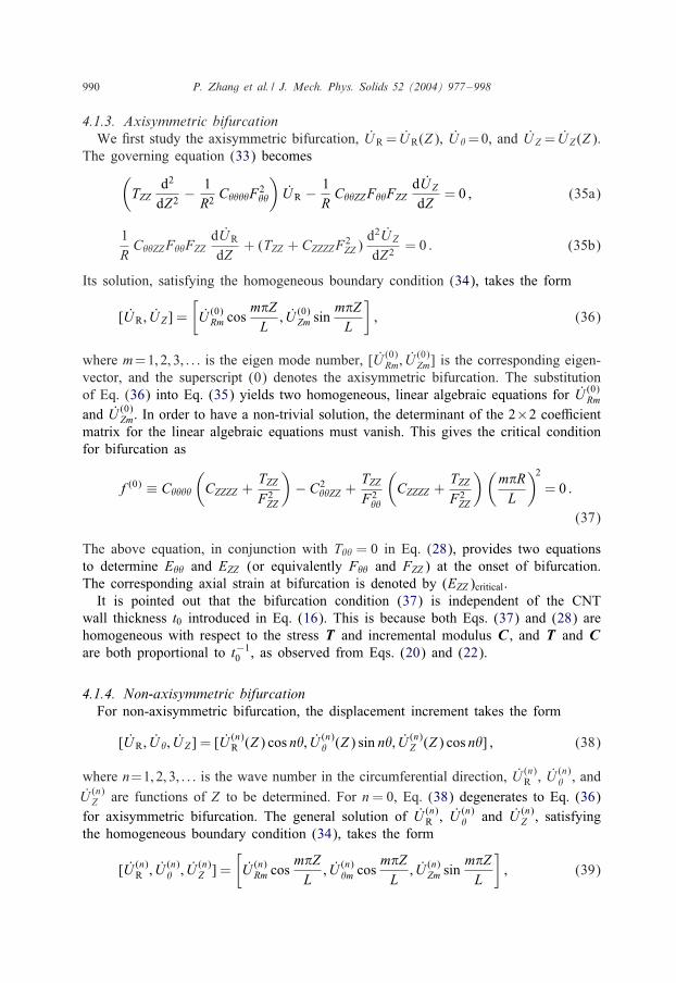
Fig. 5. Bifurcation strain for armchair CNTs.
where m= 1; 2; 3; : : : is the eigen mode number in the axial direction, and [U (n)Rm; U
(n)�m;
U (n)Zm] is the corresponding eigenvector. The substitution of Eqs. (38) and (39) into the
incremental equilibrium equation (33) yields three homogeneous, linear algebraic equa-tions for U (n)
Rm, U(n)�m and U (n)
Zm. In order to have a non-trivial solution, the determinantof the corresponding 3 × 3 coeQcient matrix must vanish. This gives the bifurcationcondition as
f(n) ≡f(0) +n2TZZ
TZZ + C�Z�ZF2��
[C����
(CZZZZ +
TZZF2ZZ
)− (C��ZZ + C�Z�Z)2
+ C�Z�Z
(C�Z�Z +
TZZF2��
)+ (n2 + 1)C����C�Z�Z
(L
m�R
)2]= 0 ; (40)
where f(0) is the function in Eq. (37) de8ned for axisymmetric bifurcation (n = 0).The critical bifurcation strains (E��)critical and (EZZ)critical at the onset of bifurcation aredetermined from Eqs. (28) and (40).
4.1.5. Bifurcation strainFig. 5 shows the bifurcation strain (EZZ)critical versus m�R=L for armchair CNTs,
where m (=1; 2; 3; : : :) is the eigen mode number in the axial direction, and R and Lare the radius and length of the CNT, respectively. Both the axisymmetric bifurcationstrain (n = 0) and non-axisymmetric bifurcation strain (n = 1; 2; 3; : : :) from Eq. (40)are presented. The axisymmetric bifurcation (n=0) gives the lowest bifurcation strain
992 P. Zhang et al. / J. Mech. Phys. Solids 52 (2004) 977–998
0.00 0.05 0.10 0.15 0.20 0.25
0.350
0.375
0.400
0.425
Armchair nanotubes
Zigzag nanotubes
(EZ
Z) cr
itica
l
R/L
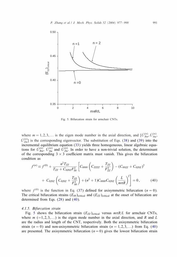
Fig. 6. Bifurcation strain for armchair and zigzag CNTs.
such that the armchair CNTs always bifurcate in the axisymmetric form. For n=0, thebifurcation strain increases very slowly with m�R=L and is essentially a constant, 0:42.Fig. 5 also indicates that the bifurcation takes place with the 8rst mode (m=1) in theaxial direction and the axisymmetric mode (n=0) in the circumferential direction. Thisis because the curve for n= 0 in Fig. 5 increases monotonically (though slowly) withm�R=L such that, at each 8xed R=L, the 8rst eigen mode m= 1 in the axial directiongives the smallest bifurcation strain. Since the CNT length is at least twice its diameter,L¿ 4R, the bifurcation strain (corresponding to n=0 and m=1) is replotted in Fig. 6for R=L less than 0.25.Fig. 6 also shows the bifurcation strain (EZZ)critical for zigzag CNTs, where R and
L are the radius and length of the CNT, respectively. The bifurcation also takes placewith the 8rst eigen mode (m = 1) in the axial direction and the axisymmetric mode(n=0) in the circumferential direction. The bifurcation strain for zigzag CNTs displaysa stronger dependence on the tube aspect ratio than the armchair CNTs, and it increaseswith R=L. For a 1 nm diameter (R= 0:5 nm) and 5 nm long nanotube, the bifurcationstrain predicted by the present atomistic-based continuum theory is around 0.37. Thisis within the range of the breaking strains reported by Yakobson et al.’s (1997) MDsimulations for the same tube aspect ratio.For a 8xed CNT aspect ratio R=L, we have calculated the bifurcation strain with two
di>erent constitutive models of CNTs, Eq. (15) which accounts for the e>ect of 8niteCNT radius and Eq. (17) which neglects such e>ect in the constitutive relation. Thenumerical results show that these two models predict identical bifurcation strains forCNTs with radius ¿ 0:35 nm. Therefore, the CNT radius (¿ 0:35nm) has essentiallyno e>ect on the bifurcation strain.

P. Zhang et al. / J. Mech. Phys. Solids 52 (2004) 977–998 993
4.2. Chiral CNTs
4.2.1. Pre-bifurcation: uniform deformationThe deformation prior to bifurcation is uniform. The non-zero components of the
Lagrangian strain are E�� and EZZ , but the shear stress T�Z does not vanish anymorebecause chiral CNTs give anisotropic material behavior. The stress is obtained fromEq. (20), and the vanishing of stress T�� = 0 gives E�� in terms of EZZ , i.e., E�� =E��(EZZ). The non-zero components of the incremental modulus obtained from Eq. (22)are C����, CZZZZ , C��ZZ = CZZ��, C�Z�Z , C���Z = C�Z�� and CZZZ� = C�ZZZ .
4.2.2. Onset of bifurcation: nonuniform increment of deformationThe increment of deformation gradient and Lagrangian strain are still given by
Eqs. (30) and (31), respectively. The stress increment in Eq. (32) becomes
T �� = C����E�� + C��ZZ EZZ + 2C���Z E�Z ; (41a)
T ZZ = CZZ��E�� + CZZZZ EZZ + 2CZZZ�E�Z ; (41b)
T �Z = T Z� = CZ���E�� + C�ZZZ EZZ + 2C�Z�Z E�Z : (41c)
The equilibrium equation (33) gives(− 1R2 C����F2
�� +2RT�Z
929�9Z + TZZ
929Z2
)U Z
+1R
[− 1RC����F2
��99� − (C���ZF2
�� + 2T�Z)99Z
]U �
+1RF��FZZ
(− 1RC���Z
99� − C��ZZ
99Z
)U Z = 0 ; (42a)
1R
[1RC����F2
��99� + (C���ZF2
�� + 2T�Z)99Z
]UR
+[1R2 C����F2
��929� 2 +
2R(C���ZF2
�� + T�Z)929�9Z + (C�Z�ZF2
�� + TZZ)929Z2
]U �
+F��FZZ
[1R2 C���Z
929� 2 +
1R(C��ZZ + C�Z�Z)
929�9Z + C�ZZZ
929Z2
]U Z = 0 ;
(42b)
1RF��FZZ
(1R2 C���Z
99� +
1RC��ZZ
99Z
)UR
+F��FZZ
[1R2 C���Z
929� 2 +
1R(C��ZZ + C�Z�Z)
929�9Z + C�ZZZ
929Z2
]U �
994 P. Zhang et al. / J. Mech. Phys. Solids 52 (2004) 977–998
0.00 0.05 0.10 0.15 0.20 0.25
0.350
0.375
0.400
0.425
0.450
Chiral nanotubes (φ0 = 6o)
n = 0 n = 1
(EZ
Z) cr
itica
l
R/L
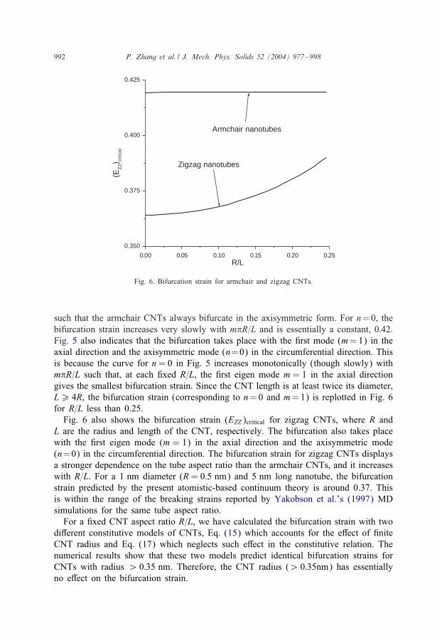
Fig. 7. Bifurcation strain for chiral CNTs.
+[1R2 C�Z�ZF2
ZZ929� 2 +
2R(C�ZZZF2
ZZ + T�Z)929�9Z
+ (CZZZZF2ZZ + TZZ)
929Z2
]U Z = 0 : (42c)
The boundary conditions in Eq. (34) becomes
U Z =9UR
9Z +T�ZTZZ
1R
(9UR
9� − U �
)=9U �
9Z = 0
at Z = 0 and Z = L : (43)
The homogeneous equations (42) and boundary conditions (43) constitute an eigenvalueproblem. They have a non-trivial solution only when the axial strain EZZ reaches theeigenvalue, (EZZ)critical, for bifurcation.
4.2.3. Bifurcation strainThe method to solve the above eigenvalue problem is the same as that in the previous
section. The displacement increment is written as U (n)s (Z) sin n�+ U (n)
c (Z) cos n�, and(42) then gives ordinary di>erential equations for U (n)
s and U (n)c . Details of the solution
method are not presented here.Fig. 7 shows the bifurcation strain (EZZ)critical versus the tube radius-to-length ratio,
R=L, for chiral CNTs with the chiral angle �0 =6◦, where �0 is the angle between thetube axis and a bond. For R=L¡ 0:118, the axisymmetric bifurcation (n=0) occurs, andthe bifurcation strain increases with R=L (similar to zigzag CNTs in Fig. 6). However,for R=L¿ 0:118, the 8rst non-axisymmetric mode (n=1) takes place, and the bifurcation
P. Zhang et al. / J. Mech. Phys. Solids 52 (2004) 977–998 995
strain decreases with the increasing R=L. Contrary to armchair and zigzag CNTs, the8rst non-axisymmetric bifurcation mode can be activated in chiral CNTs, though highermodes (n¿ 2) never take place. We have studied other chiral nanotubes with thechiral angle �0 between 0◦ and 30◦, and have also observed that the non-axisymmetricbifurcation may be activated.
5. The cuto# function
The cuto> function fc in Eq. (4) introduces a dramatic increase in the interatomicforce at the cuto> distance R(1) = 0:17 nm (Belytschko et al., 2002). This strangefeature in the force is a result of the cuto> function on the interatomic potential. Inorder to avoid this unphysical feature, Belytschko et al. (2002) used the modi8edMorse potential instead, while Shenderova et al. (2000) used a larger cuto> distancein Brenner’s (1990) interatomic potential. Since the cuto> function in Eq. (4) has adiscontinuous second order derivative, the incremental modulus tensor C in Eq. (22) isalso discontinuous at the cuto> distance 0:17 nm, and this may inVuence the bifurcationstrain predicted by the present analysis. To exclude this arti8cial e>ect of the cuto>function fc, we do not use the cuto> function in this paper. The results presentedin Figs. 5–7 are obtained with fc replaced by unity (one). Since the bifurcation stilloccurs without the cuto> function, it must be intrinsic to CNTs under tension.The important question now is whether the bifurcation strain will change signi8cantly
if the cuto> function is used. For zigzag CNTs, we have found all three bond lengthsat the bifurcation strain 0.37 [accounting for the shift vector �, or equivalently � asin Eq. (19)] to be less than the cuto> distance 0:17 nm, which means the predictedbifurcation strain will remain the same even if the cuto> function is used. However,for armchair CNTs, two bond lengths are larger than the cuto> distance 0:17 nm atthe predicted bifurcation strain 0.42, which suggests that the cuto> function may inVu-ence the predicted bifurcation strain. In fact, our calculations accounting for the cuto>function show that the bifurcation strain becomes 0.50 for armchair CNTs. This valueagrees well with the maximum fracture nucleation strain for armchair CNTs reportedin MD simulations with the cuto> function (Yakobson et al., 1997), but is higher than0.42 reported in Fig. 5 without the cuto> function. Therefore, even though the bifur-cation is intrinsic to CNTs under tension, the bifurcation strain predicted may dependon the cuto> function.It is noted that the bifurcation strain 0.37 reported in Fig. 6 is still higher than the
fracture strain reported in Belytschko et al.’s (2002) MD simulations based on themodi8ed Morse potential and in Dumitrica et al.’s (2003) tight binding calculations.The use of di>erent potentials may be responsible for this di>erence.
6. Concluding remarks
We have proposed an atomistic-based continuum theory for CNTs based on the inter-atomic potential. It links the continuum constitutive model for CNTs to the interatomic
996 P. Zhang et al. / J. Mech. Phys. Solids 52 (2004) 977–998
potential of carbon (Brenner, 1990). We have applied the atomistic-based continuumtheory to model fracture nucleation in single-wall CNTs under tension as a bifurcationproblem. The results agree reasonably well with MD simulations without any parameter8tting. The proposed approach to link continuum analysis to the interatomic potentialcan be applied to other nano-structured materials if the interatomic potential and theatomic structure are known.
Acknowledgements
Y.H. acknowledges helpful discussions with Professors T. Belytschko, W.K. Liu,R.S. Ruo>, B.I. Yakobson, and the support from NSF (grants #0099909 and #0103257)and NSFC. K.C.H. acknowledges the support form NSFC. We thank an anonymousreviewer who pointed out a new interatomic potential for carbon (Brenner et al., 2002).
References
Arroyo, M., Belytschko, T., 2002. An atomistic-based 8nite deformation membrane for single layer crystalline8lms. J. Mech. Phys. Solids 50, 1941–1977.
Belytschko, T., Xiao, S.P., Schatz, G.C., Ruo>, R.S., 2002. Atomistic simulations of nanotube fracture. Phys.Rev. B 65, 235430-1–235430-8.
Born, M., Huang, K., 1954. Dynamical theory of the crystal lattices. Oxford University Press, Oxford.Brenner, D.W., 1990. Empirical potential for hydrocarbons for use in simulating the chemical vapor
deposition of diamond 8lms. Phys. Rev. B 42, 9458–9471.Brenner, D.W., Shenderova, O.A., Harrison, J.A., Stuart, S.J., Ni, B., Sinnott, S.B., 2002. A second-generation
reactive empirical bond order (rebo) potential energy expression for hydrocarbons. J. Phys.: Condens.Matter 14, 783–802.
Cornwell, C.F., Wille, L.T., 1997. Elastic properties of single-walled carbon nanotubes in compression. SolidState Commun. 101, 555–558.
Dumitrica, T., Belytschko, T., Yakobson, B.I., 2003. Bond-breaking bifurcation states in carbon nanotubefracture. J. Chem. Phys. 118, 9485–9488.
Ebbesen, T.W., Ajayan, P.M., 1992. Large-scale synthesis of carbon nanotubes. Nature 358, 220–222.Fan, S., Chapline, M.G., Franklin, N.R., Tombler, T., Cassell, A.M., Dai, H., 1999. Self-oriented regular
arrays of carbon nanotubes and their 8eld emission properties. Science 283, 512–514.Gao, H., Huang, Y., Abraham, F.A., 2001. Continuum and atomistic studies of intersonic crack propagation.
J. Mech. Phys. Solids 49, 2113–2132.Goze, C., Vaccarini, L., Henrard, L., Bernier, P., Hernandez, E., Rubio, A., 1999. Elastic and mechanical
properties of carbon nanotubes. Synth. Met. 103, 2500–2501.Gurtin, M.E., Murdoch, A.I., 1975. A continuum theory of elastic material surfaces. Arch. Ration. Mech.
Anal. 57, 291–323.Halicioglu, T., 1998. Stress calculations for carbon nanotubes. Thin Solid Films 312, 11–14.HernMandez, E., Goze, C., Bernier, P., Rubio, A., 1998. Elastic properties of C and BxCyNz composite
nanotubes. Phys. Rev. Lett. 80, 4502–4505.HernMandez, E., Goze, C., Bernier, P., Rubio, A., 1999. Elastic properties of single-wall nanotubes. Appl.
Phys. A 68, 287–292.Iijima, S., 1991. Helical microtubules of graphite carbon. Nature 354, 56–58.Jiang, H., Zhang, P., Liu, B., Huang, Y., Geubelle, P.H., Gao, H., Hwang, K.C., 2003. The e>ect of nanotube
radius on the constitutive model for carbon nanotubes. Comput. Mater. Sci. 28, 429–442.Krishnan, A., Dujardin, E., Ebbesen, T.W., Yianilos, P.N., Treacy, M.M.J., 1998. Young’s modulus of
single-walled nanotubes. Phys. Rev. B 58, 14013–14019.
P. Zhang et al. / J. Mech. Phys. Solids 52 (2004) 977–998 997
Lier, G.V., Alsenoy, C.V., Doran, V.V., Geerlings, P., 2000. Ab intitio study of the elastic properties ofsingle-walled carbon nanotubes and graphene. Chem. Phys. Lett. 326, 181–185.
Lourie, O., Wagner, H.D., 1998. Evaluation of young’s modulus of carbon nanotubes by micro-ramansoectroscopy. J. Mater. Res. 13, 2418–2422.
Lu, J.P., 1997. Elastic properties of carbon nanotubes and nanoropes. Phys. Rev. Lett. 79, 1297–1300.Miller, R., Ortiz, M., Phillips, R., Shenoy, V., Tadmor, E.B., 1998a. Quasicontinuum models of fracture and
plasticity. Eng. Fract. Mech. 61, 427–444.Miller, R., Tadmor, E.B., Phillips, R., Ortiz, M., 1998b. Quasicontinuum simulation of fracture at the atomic
scale. Modelling and Simulation in Mater. Sci. Eng. 6, 607–638.Milstein, F., 1980. Review: theoretical elastic behaviour at large strains. J. Mater. Sci. 15, 1071–1084.Molina, J.M., Savinsky, S.S., Khokhriakov, N.V., 1996. A tight-binding model for calculations of structures
and properties of graphitic nanotubes. J. Chem. Phys. 104, 4652–4656.Muster, J., Burghard, M., Roth, S., Duesberg, G.S., HernMandez, E., Rubio, A., 1998. Scanning force
microscopy characterization of individual carbon nanotubes on electrode arrays. J. Vac. Sci. Technol.B 16, 2796–2801.
Overney, G., Zhong, W., TomManek, D., 1993. Structural rigidity and low-frequency vibrational modes oflong carbon tubules. Z. Phys. D: Atoms Mol. Clusters 27, 93–96.
Pan, Z.W., Xie, S.S., Lu, L., Chang, B.H., Sun, L.F., Zhou, W.Y., Wang, G., 1999. Tensile tests of ropesof very long aligned multiwall carbon nanotubes. Appl. Phys. Lett. 74, 3152–3154.
Popov, V.N., van Doren, V.E., Balkanski, M., 2000. Elastic properties of single-walled carbon nanotubes.Phys. Rev. B 61, 3078–3084.
Prylutskyy, Y.I., Durov, S.S., Ogloblya, O.V., Buzaneva, E.V., Schar>, P., 2000. Molecular dynamicssimulations of mechanical, vibrational and electronic properties of carbon nanotubes. Comput. Mater.Sci. 17, 352–355.
Qian, D., Wagner, G.J., Liu, W.K., Yu, M.-F., Ruo>, R.S., 2002. Mechanics of carbon nanotubes. Appl.Mech. Rev. 55, 495–533.
Robertson, D.H., Brenner, D.W., Mintmire, J.W., 1992. Energetics of nanoscale graphitic tubules. Phys. Rev.B 45, 12592–12595.
Salvetat, J.-P., Briggs, G. A.D., Bonard, J.-M., Bacsa, R.R., Kulik, A.J., 1999. Elastic and shear moduli ofsingle-walled carbon nanotube ropes. Phys. Rev. Lett. 82, 944–947.
SManchez-Portal, D., Artacho, E., Soler, J.M., Rubio, A., OrdejMon, P., 1999. Ab Initio structural, elastic, andvibrational properties of carbon nanotubes. Phys. Rev. B 59, 12678–12688.
Shenderova, O.A., Brenner, D.W., Omeltchenko, A., Su, X., Yang, L.H., 2000. Atomistic modeling of thefracture of polycrystalline diamond. Phys. Rev. B 61, 3877–3888.
Shenoy, V.B., Miller, R., Tadmor, E.B., Phillips, R., Ortiz, M., 1998. Quasicontinuum models of interfacialstructure and deformation. Phys. Rev. Lett. 80, 742–745.
Shenoy, V.B., Miller, R., Tadmor, E.B., Rodney, D., Phillips, R., Ortiz, M., 1999. An adaptive 8nite elementapproach to atomic-scale mechanics—the quasicontinuum method. J. Mech. Phys. Solids 47, 611–642.
Srivastava, D., Menon, M., Cho, K.J., 2001. Computational nanotechnology with carbon nanotubes andfullerenes. Comput. Sci. Eng. 3, 42–55.
Tadmor, E.B., Ortiz, M., Philips, R., 1996a. Quasicontinuum analysis of defects in solids. Philos. Mag.A 73, 1529–1563.
Tadmor, E.B., Philips, R., Ortiz, M., 1996b. Mixed atomistic and continuum models of deformation in solids.Langmuir 12, 4529–4534.
Tadmor, E.B., Smith, G.S., Bernstein, N., Kaxiras, E., 1999. Mixed 8nite element and atomistic formulationfor complex crystals. Phys. Rev. B 59, 235–245.
Terso>, J., 1988. New empirical approach for the structure and energy of covalent systems. Phys. Rev.B 37, 6991–7000.
Thess, A., Lee, R., Nikolaev, P., Dai, H.J., Petit, P., Robert, J., Xu, C.H., Lee, Y.H., Kim, S.G., Rinzler,A.G., Colbert, D.T., Scuseria, G.E., Tomanek, D., Fischer, J.E., Smalley, R.E., 1996. Crystalline ropes ofmetallic carbon nanotubes. Science 273, 483–487.
Tombler, T.W., Zhou, C., Alexseyev, L., Kong, J., Dai, H., Liu, L., Jayanthi, C.S., Tang, M., Wu, S.-Y.,2000. Reversible electromechanical characteristics of carbon nanotubes under local-probe manipulation.Nature 405, 769–772.
998 P. Zhang et al. / J. Mech. Phys. Solids 52 (2004) 977–998
Treacy, M.M.J., Ebbesen, T.W., Gibson, J.M., 1996. Exceptionally high Young’s modulus observed forindividual carbon nanotubes. Nature 381, 678–680.
Vaccarini, L., Goze, C., Henrard, L., HernMandez, E., Bernier, P., Rubio, A., 2000. Mechanical and electronicproperties of carbon and boron-nitride nanotubes. Carbon 38, 1681–1690.
Weiner, J.H., 1983. Statistical Mechanics of Elasticity. Wiley, New York.Wong, E.W., Sheehan, P.E., Lieber, C.M., 1997. Nanobeam mechanics: elasticity, strength, and toughness
of nanorods and nanotubes. Science 277, 1971–1975.Yakobson, B.I., Avouris, P., 2001. Mechanical properties of carbon nanotubes. In: Dresselhaus, M.S.,
Dresselhaus, G., Avouris, P. (Eds.), Carbon Nanotubes. Topics in Applied Physics, Vol. 80. pp. 287–329,Springer Verlag, Berlin-Heidelberg, Germany.
Yakobson, B.I., Brabec, C.J., Bernholc, J., 1996. Nanomechanics of carbon tubes: instabilities beyond linearresponse. Phys. Rev. Lett. 76, 2511–2514.
Yakobson, B.I., Campbell, M.P., Brabec, C.J., Bernholc, J., 1997. High strain rate fracture and C-chainunraveling in carbon nanotubes. Comput. Mater. Sci. 8, 341–348.
Yu, M.-F., Lourie, O., Dyer, M.J., Moloni, K., Kelly, T.F., Ruo>, R.S., 2000. Strength and breakingmechanism of multiwalled carbon nanotubes under tensile load. Science 287, 637–640.
Zhang, P., Huang, Y., Gao, H., Hwang, K.C., 2002a. Fracture nucleation in single-wall carbon nanotubesunder tension: a continuum analysis incorporating interatomic potentials. J. Appl. Mech. 69, 454–458.
Zhang, P., Huang, Y., Geubelle, P.H., Klein, P.A., Hwang, K.C., 2002b. The elastic modulus of single-wallcarbon nanotubes: a continuum analysis incorporating interatomic potentials. Int. J. Solids Struct. 39,3893–3906.
Zhou, G., Duan, W., Gu, B., 2001. First-principles study on morphology and mechanical properties ofsingle-walled carbon nanotube. Chem. Phys. Lett. 333, 344–349.

![Concurrent atomistic-continuum simulations of uniaxial ...€¦ · atomic trajectory inside the materials in experiments, numerical simulations via atomistic methods [11,12] and discrete](https://img.pdfslide.us/doc/110x75/5fb2485e21a30672d07b36b4/concurrent-atomistic-continuum-simulations-of-uniaxial-atomic-trajectory-inside.jpg)