Embed Size (px)
Citation preview

An assessment of high-pressure freezing and freeze substitution protocols for cultured cells Gerald Shami1, Delfine Cheng1, Jeffrey Henriquez1 and Filip Braet1,2
1 School of Medical Sciences (Discipline of Anatomy and Histology) – The Bosch Institute, The University of Sydney, NSW 2006, Australia
2 Australian Centre for Microscopy and Microanalysis, The University of Sydney, NSW 2006, Australia
Since the advent of cryo-electron microscopy (cryo-EM), the close-to-life and fine structure preservation of biological samples has become a realized procurement, surpassing the fixation quality and avoiding the numerous artifacts inherent to conventional chemical preservation methods. Cryo-EM techniques such as high-pressure freezing followed by freeze-substitution (HPF/FS) have facilitated the simultaneous immobilization of all supramolecular complexes within a sample within milliseconds, providing a true snapshot of the cell at the moment of freezing.
Based on these attributes HPF/FS presents as an invaluable tool for the quick immobilization, preservation and investigation of such highly dynamic processes as endocytic vesicular internalization. In this contribution we will report on the structural preservation of cells grown on sapphire discs for the subsequent preparation for HPF/FS studies. We will outline different notes and tricks that contributed to the success of subcellular preservation for subsequent high-resolution transmission electron microscopy (TEM) studies. All of this will be illustrated on cultured Caco-2 colorectal cancer cells (CRC) with a special emphasis on the organization of the various membrane-bound vesicles (MBVs) that harbor within the cell cytoplasm.
Keywords: electron microscopy; high-pressure freezing; freeze substitution; caveolae; coated pits; clathrin-coated vesicles; epithelial transport; vesicles
1. Introduction
High-pressure freezing (HPF) is an ultrarapid cryo-immobilization means of immobilizing all molecules within a sample within milliseconds, providing a true snapshot of the cell at the moment of freezing [1]. Unlike conventional biological sample preparation for electron microscopy (EM) where the process is totally chemical, here it is a physical process [2]. Cryo-immobilization is achieved via vitrification, a process whereby the specimen is cooled very rapidly to liquid nitrogen temperatures, so that the water in and around the specimen becomes vitreous, i.e. an amorphous or non-crystalline liquid; a phenomenon that has been demonstrated to be both temperature- and pressure-dependent [3, 4]. During the process of HPF, a pressure of 2100 bar (1 bar = 100 kPa) is placed on the sample only milliseconds prior to being cooled by jet of liquid nitrogen, resulting in the formation of amorphous vitreous ice that does not expand upon solidification [4]. Under 2100 bar, the melting point of water as well as the temperature for the nucleation of ice crystals in pure water is lowered to -22˚C and -90˚C respectively, thereby slowing the nucleation of hexagonal ice crystals which may cause artefactual damage to the sample [5]. Freeze substitution (FS) is the process whereby ice is removed from a cryo-fixed sample by an organic solvent at a temperature below the recrystallization temperature of water (-90˚C) [6]. After dehydration, the temperature is progressively raised and other procedures such as infiltration with resin can be performed. Thus, FS allows the optimal preservation of ultrastructure achieved by cryo-fixation, combined with resin embedding, due to the avoidance of artifacts caused during dehydration at room temperature [7]. Furthermore, in contrast to cryo-electron microscopy of vitreous sections (CEMOVIS), imaging of resin embedded samples as in HPF/FS presents a number of advantages, including: the ability to use heavy metal salt contrasting agents in order to enhance the visualization of biological structures, and; increased sample resistance to the damaging electron beam, facilitating a higher signal-to-noise ratio. Due to these inherent characteristics, HPF/FS presents as an invaluable tool for the routine preparation of biological samples for high-resolution fine-structure investigations. In this Chapter, we will out outline our road to success in the ultrastructural preservation of cells cultured on sapphire discs with a special emphasis on the notes and tricks involved in this technical demanding endeavor. We will present data—and discuss in-depth—in which we directly compare chemically versus physical fixed samples.
2. Materials & Methods
2.1 Chemical fixation comparison: glutaraldehyde, osmium tetroxide & tannic acid (GOT) protocol
In order to provide a comparison between chemical and HPF/FS methods, below we detail a chemical fixation protocol optimized for the specific visualization of membrane-bound vesicles. Caco-2 CRC (American Type Culture Collection, cat. no. HTB-37, Rockville, Maryland USA) cells were plated on carbon-coated coverslips and cultured in complete Dulbecco’s Modified Eagle Medium (DMEM) at a density of 1.3 ×
Microscopy: advances in scientific research and education (A. Méndez-Vilas, Ed.)
© FORMATEX 2014
__________________________________________________________________
10
104 cells/cm2 in 6-well plates (described in [8, 9]). After a confluence of 70-80% has been reached cells were rinsed with 37˚C 0.1 M phosphate buffered saline (PBS) pH 7.4 and fixed with 2% glutaraldehyde in 0.1 M sodium cacodylate buffer pH 7.4 containing 0.1 M sucrose, for 1 hour at room temperature. Samples were post-fixed in 1% osmium tetroxide in sodium cacodylate buffer for 1 hour at room temperature in darkness, in order to fix lipids and enhance contrast of cell membranes. Post-osmication, samples were incubated in 1% tannic acid in 0.1 M sodium cacodylate buffer for 20 minutes and successively rinsed with distilled water. Samples were dehydrated in a graded series of ethanol concentrations, from 30% to absolute. Infiltration was performed in a graded series of Epon resin in absolute ethanol (25%, 50%, 75%, and 100%) and polymerized at 60°C for 24 hours. Silver-gold (70 nm) ultrathin sections were generated using a Leica EM UC7 ultramicrotome equipped with a diamond knife and mounted onto 200-mesh copper grids. Sections were stained with an aqueous solution of 2% uranyl acetate for 10 minutes, followed by Reynold’s lead citrate for 10 minutes. Samples were imaged with a JEOL 2100 TEM operating at 200 kV. Images (1024 × 1024 pixels) were acquired with a bottom-mounted UltraScan® 4000 large-format CCD camera (model no. 895, Gatan, Japan) (binning factor 2, binned pixel size 30 µm).
2.2 Standard TEM HPF/FS (SHPF) Protocol
2.2.1 Cell culture on 1.4 mm sapphire coverslips
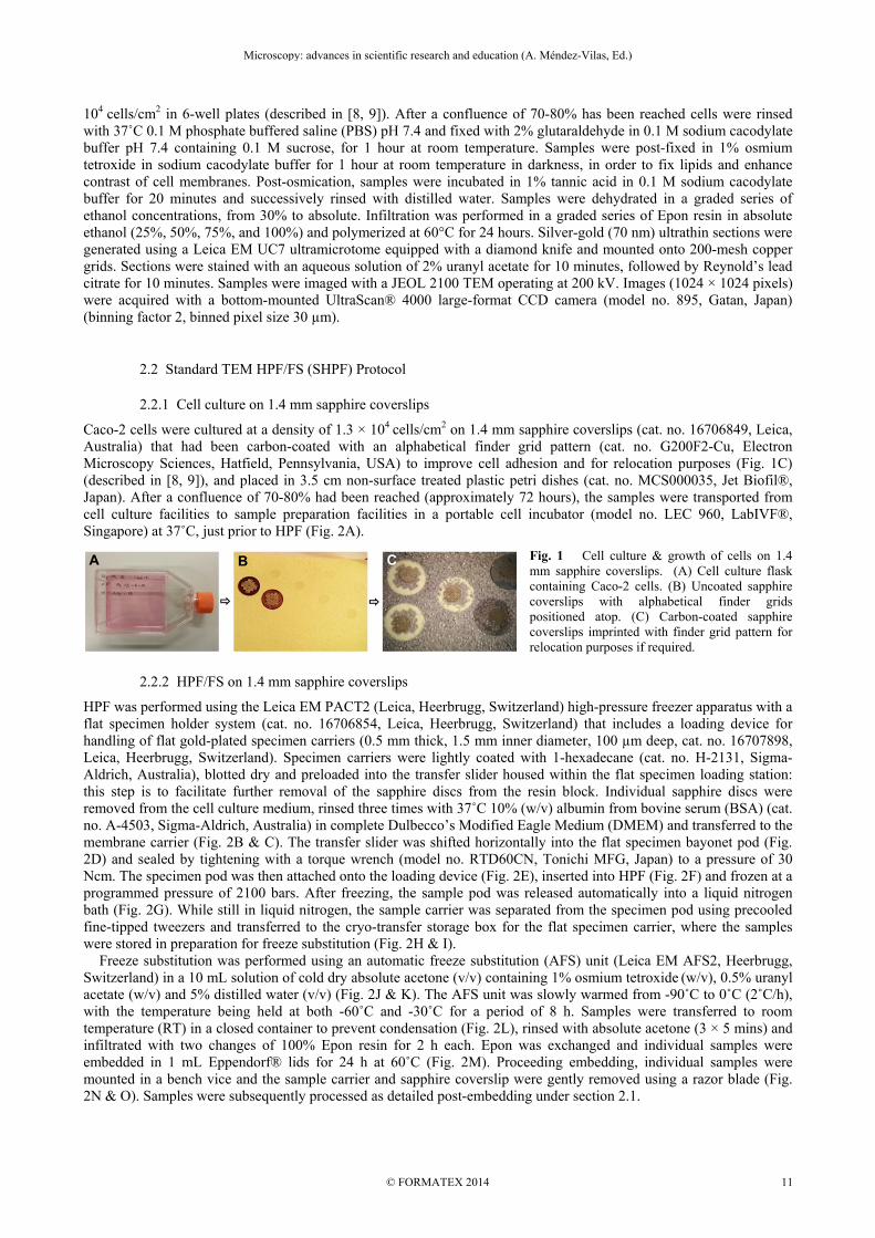
Caco-2 cells were cultured at a density of 1.3 × 10⁴ cells/cm2 on 1.4 mm sapphire coverslips (cat. no. 16706849, Leica, Australia) that had been carbon-coated with an alphabetical finder grid pattern (cat. no. G200F2-Cu, Electron Microscopy Sciences, Hatfield, Pennsylvania, USA) to improve cell adhesion and for relocation purposes (Fig. 1C) (described in [8, 9]), and placed in 3.5 cm non-surface treated plastic petri dishes (cat. no. MCS000035, Jet Biofil®, Japan). After a confluence of 70-80% had been reached (approximately 72 hours), the samples were transported from cell culture facilities to sample preparation facilities in a portable cell incubator (model no. LEC 960, LabIVF®, Singapore) at 37˚C, just prior to HPF (Fig. 2A).
Fig. 1 Cell culture & growth of cells on 1.4 mm sapphire coverslips. (A) Cell culture flask containing Caco-2 cells. (B) Uncoated sapphire coverslips with alphabetical finder grids positioned atop. (C) Carbon-coated sapphire coverslips imprinted with finder grid pattern for relocation purposes if required.
2.2.2 HPF/FS on 1.4 mm sapphire coverslips
HPF was performed using the Leica EM PACT2 (Leica, Heerbrugg, Switzerland) high-pressure freezer apparatus with a flat specimen holder system (cat. no. 16706854, Leica, Heerbrugg, Switzerland) that includes a loading device for handling of flat gold-plated specimen carriers (0.5 mm thick, 1.5 mm inner diameter, 100 µm deep, cat. no. 16707898, Leica, Heerbrugg, Switzerland). Specimen carriers were lightly coated with 1-hexadecane (cat. no. H-2131, Sigma-Aldrich, Australia), blotted dry and preloaded into the transfer slider housed within the flat specimen loading station: this step is to facilitate further removal of the sapphire discs from the resin block. Individual sapphire discs were removed from the cell culture medium, rinsed three times with 37˚C 10% (w/v) albumin from bovine serum (BSA) (cat. no. A-4503, Sigma-Aldrich, Australia) in complete Dulbecco’s Modified Eagle Medium (DMEM) and transferred to the membrane carrier (Fig. 2B & C). The transfer slider was shifted horizontally into the flat specimen bayonet pod (Fig. 2D) and sealed by tightening with a torque wrench (model no. RTD60CN, Tonichi MFG, Japan) to a pressure of 30 Ncm. The specimen pod was then attached onto the loading device (Fig. 2E), inserted into HPF (Fig. 2F) and frozen at a programmed pressure of 2100 bars. After freezing, the sample pod was released automatically into a liquid nitrogen bath (Fig. 2G). While still in liquid nitrogen, the sample carrier was separated from the specimen pod using precooled fine-tipped tweezers and transferred to the cryo-transfer storage box for the flat specimen carrier, where the samples were stored in preparation for freeze substitution (Fig. 2H & I). Freeze substitution was performed using an automatic freeze substitution (AFS) unit (Leica EM AFS2, Heerbrugg, Switzerland) in a 10 mL solution of cold dry absolute acetone (v/v) containing 1% osmium tetroxide (w/v), 0.5% uranyl acetate (w/v) and 5% distilled water (v/v) (Fig. 2J & K). The AFS unit was slowly warmed from -90˚C to 0˚C (2˚C/h), with the temperature being held at both -60˚C and -30˚C for a period of 8 h. Samples were transferred to room temperature (RT) in a closed container to prevent condensation (Fig. 2L), rinsed with absolute acetone (3 × 5 mins) and infiltrated with two changes of 100% Epon resin for 2 h each. Epon was exchanged and individual samples were embedded in 1 mL Eppendorf® lids for 24 h at 60˚C (Fig. 2M). Proceeding embedding, individual samples were mounted in a bench vice and the sample carrier and sapphire coverslip were gently removed using a razor blade (Fig. 2N & O). Samples were subsequently processed as detailed post-embedding under section 2.1.
Microscopy: advances in scientific research and education (A. Méndez-Vilas, Ed.)
© FORMATEX 2014
__________________________________________________________________
11
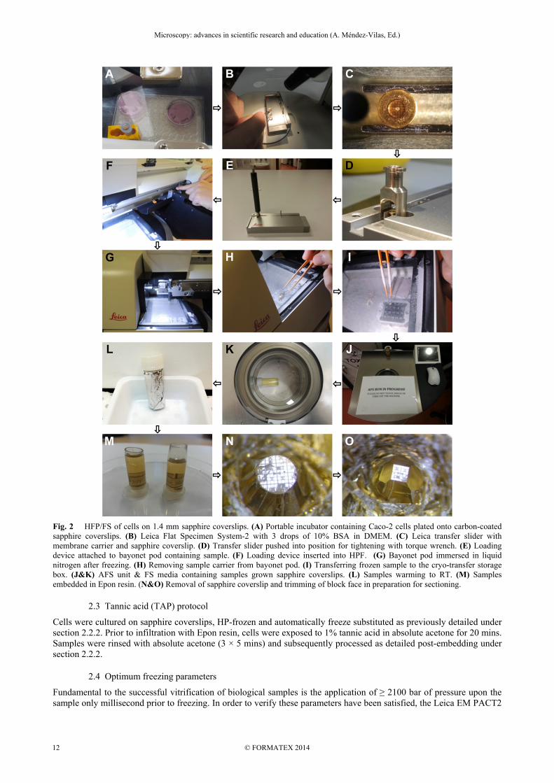
Fig. 2 HFP/FS of cells on 1.4 mm sapphire coverslips. (A) Portable incubator containing Caco-2 cells plated onto carbon-coated sapphire coverslips. (B) Leica Flat Specimen System-2 with 3 drops of 10% BSA in DMEM. (C) Leica transfer slider with membrane carrier and sapphire coverslip. (D) Transfer slider pushed into position for tightening with torque wrench. (E) Loading device attached to bayonet pod containing sample. (F) Loading device inserted into HPF. (G) Bayonet pod immersed in liquid nitrogen after freezing. (H) Removing sample carrier from bayonet pod. (I) Transferring frozen sample to the cryo-transfer storage box. (J&K) AFS unit & FS media containing samples grown sapphire coverslips. (L) Samples warming to RT. (M) Samples embedded in Epon resin. (N&O) Removal of sapphire coverslip and trimming of block face in preparation for sectioning.
2.3 Tannic acid (TAP) protocol
Cells were cultured on sapphire coverslips, HP-frozen and automatically freeze substituted as previously detailed under section 2.2.2. Prior to infiltration with Epon resin, cells were exposed to 1% tannic acid in absolute acetone for 20 mins. Samples were rinsed with absolute acetone (3 × 5 mins) and subsequently processed as detailed post-embedding under section 2.2.2.
2.4 Optimum freezing parameters
Fundamental to the successful vitrification of biological samples is the application of ≥ 2100 bar of pressure upon the sample only millisecond prior to freezing. In order to verify these parameters have been satisfied, the Leica EM PACT2
Microscopy: advances in scientific research and education (A. Méndez-Vilas, Ed.)
© FORMATEX 2014
__________________________________________________________________
12
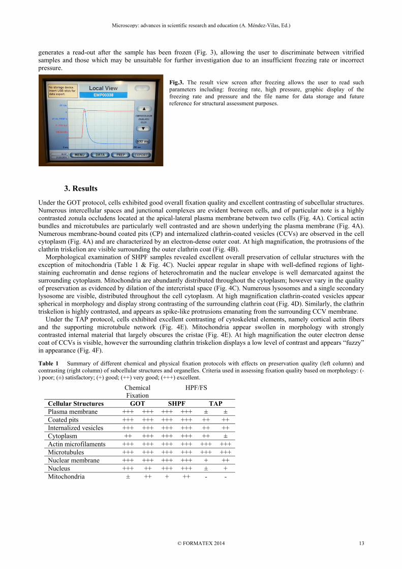
generates a read-out after the sample has been frozen (Fig. 3), allowing the user to discriminate between vitrified samples and those which may be unsuitable for further investigation due to an insufficient freezing rate or incorrect pressure.
Fig.3. The result view screen after freezing allows the user to read such parameters including: freezing rate, high pressure, graphic display of the freezing rate and pressure and the file name for data storage and future reference for structural assessment purposes.
3. Results
Under the GOT protocol, cells exhibited good overall fixation quality and excellent contrasting of subcellular structures. Numerous intercellular spaces and junctional complexes are evident between cells, and of particular note is a highly contrasted zonula occludens located at the apical-lateral plasma membrane between two cells (Fig. 4A). Cortical actin bundles and microtubules are particularly well contrasted and are shown underlying the plasma membrane (Fig. 4A). Numerous membrane-bound coated pits (CP) and internalized clathrin-coated vesicles (CCVs) are observed in the cell cytoplasm (Fig. 4A) and are characterized by an electron-dense outer coat. At high magnification, the protrusions of the clathrin triskelion are visible surrounding the outer clathrin coat (Fig. 4B). Morphological examination of SHPF samples revealed excellent overall preservation of cellular structures with the exception of mitochondria (Table 1 & Fig. 4C). Nuclei appear regular in shape with well-defined regions of light-staining euchromatin and dense regions of heterochromatin and the nuclear envelope is well demarcated against the surrounding cytoplasm. Mitochondria are abundantly distributed throughout the cytoplasm; however vary in the quality of preservation as evidenced by dilation of the intercristal space (Fig. 4C). Numerous lysosomes and a single secondary lysosome are visible, distributed throughout the cell cytoplasm. At high magnification clathrin-coated vesicles appear spherical in morphology and display strong contrasting of the surrounding clathrin coat (Fig. 4D). Similarly, the clathrin triskelion is highly contrasted, and appears as spike-like protrusions emanating from the surrounding CCV membrane. Under the TAP protocol, cells exhibited excellent contrasting of cytoskeletal elements, namely cortical actin fibers and the supporting microtubule network (Fig. 4E). Mitochondria appear swollen in morphology with strongly contrasted internal material that largely obscures the cristae (Fig. 4E). At high magnification the outer electron dense coat of CCVs is visible, however the surrounding clathrin triskelion displays a low level of contrast and appears “fuzzy” in appearance (Fig. 4F).
Table 1 Summary of different chemical and physical fixation protocols with effects on preservation quality (left column) and contrasting (right column) of subcellular structures and organelles. Criteria used in assessing fixation quality based on morphology: (-) poor; (±) satisfactory; (+) good; (++) very good; (+++) excellent.
Chemical Fixation
HPF/FS
Cellular Structures GOT SHPF TAP Plasma membrane +++ +++ +++ +++ ± ± Coated pits +++ +++ +++ +++ ++ ++ Internalized vesicles +++ +++ +++ +++ ++ ++ Cytoplasm ++ +++ +++ +++ ++ ± Actin microfilaments +++ +++ +++ +++ +++ +++ Microtubules +++ +++ +++ +++ +++ +++ Nuclear membrane +++ +++ +++ +++ + ++ Nucleus +++ ++ +++ +++ ± + Mitochondria ± ++ + ++ - -
Microscopy: advances in scientific research and education (A. Méndez-Vilas, Ed.)
© FORMATEX 2014
__________________________________________________________________
13

Fig. 4 (A) Zonula occludens formation along the apical-lateral plasma membrane between two cells (zo). Numerous microtubules (mt) are visible within the cell cytoplasm and two internalized clathrin-coated vesicles (cv) are shown, closely associated with the plasma membrane. (B) High-power micrograph of a plasma membrane-bound coated pit (cp), showing highly-contrasted protrusions of the clathrin triskelion (cts). (C) The rapid rate of preservation obtained via HP-freezing is clearly illustrated via the simultaneous stabilization of cellular structures within a large portion of the sample. Two large euchromatic nuclei (n) are shown, bounded by the nuclear envelope. The cytoplasm is scattered with numerous organelles including mitochondria (m) and primary (l) and secondary lysosomes (sl). (D) High-power of an internalized clathrin-coated vesicle within the cell cytoplasm showing clear protrusions of the clathrin triskelion (cts), which appear spike-like in appearance. (E) Bundles of cortical actin filaments (a) are visible underlying the plasma membrane, supported by an underlying microtubule (mt) network. A single mitochondrion (m) is visible within the cell cytoplasm, and its internal detail is almost completely obscured due to intense contrasting. (F) High-power image of a clathrin-coated vesicle internalized with the cell cytoplasm, surrounded by the clathrin triskelion (cts), which appears fuzzy in appearance, and displays a low level of contrast. A cluster of ribosomes (r) are similarly shown throughout the cell cytoplasm.
4. Discussion & Concluding Remarks
Throughout the literature, much ambiguity exists regarding the vesicles present at the level of the plasma membrane within the Caco-2 CRC cell line. Thus, this study aimed to test a number of specimen preparation protocols for the specific visualization of these structures, whilst also noting the effects of these protocols on the fixation quality and degree of contrasting of specific sub-cellular structures (see, Table 1). Amongst all fixation protocols tested cells exhibited an analogous presence of subcellular structures, however, varied in the degree of preservation and contrast. Close analysis of the various protocols revealed that the SHPF protocol produced the most comprehensive preservation and contrasting of the subcellular structures listed under Table 1. Of particular note was the preservation and contrasting of CCVs in which such fine-structure information as the spike-like protrusions of the clathrin triskelion from the outer CCV coat were apparent. The excellent fixation quality achieved was attributed primarily to the rapid rate of fixation and simultaneous stabilization of sub-cellular components which is inherent to HPF; providing a true snapshot of such dynamic processes as endocytic vesicle internalization. Subsequent low-temperature freeze-substitution of dehydrating agents allowed for the removal of water at temperatures low enough to avoid the damaging effects of ambient-temperature dehydration and which is indeed illustrated in the excellent preservation of fine-structure detail in SHPF samples. Noteworthy, close analysis at the electron microscopy level revealed no evidence of caveolae. This is in agreement with the findings of Vogel et al. and Mirre et al., who demonstrated that wild-type Caco-2 cells do not express detectable levels of caveolin-1 (Cav-1) and have extremely few, if any caveolae [10, 11]. Moreover, the requirement of Cav-1 as the key structural protein for caveolae biogenesis is extensively documented throughout the literature, providing further justification for the absence of caveolae in our findings [12-14]. In summary, we herein present a thorough step-by-step workflow for the preparation of biological samples grown on sapphire coverslips for ultrastructural studies. Furthermore, we provide a comparative analysis of a variety of chemical
Microscopy: advances in scientific research and education (A. Méndez-Vilas, Ed.)
© FORMATEX 2014
__________________________________________________________________
14

and physical fixation protocols for the specific visualization of the aforementioned structures. In so doing, we validated the applicability of specific specimen preparation protocols for the preservation and contrasting of membrane-associated vesicles.
Acknowledgements The authors acknowledge the facilities, as well as technical and administrative assistance from staff, of the AMMRF at the Australian Centre for Microscopy & Microanalysis of the University of Sydney. The authors are also indebted to Leica Microsystems (Australia) and Jeol (Australasia) for their continuing support.
References [1] McDonald KL, Auer M. High-pressure freezing, cellular tomography, and structural cell biology. BioTechniques 2006;41:137,
9, 41 passim. [2] Fegan N, Webb RI, Hayward AC, Stirling GR. Cryofixation and Cryosubstitution as a Method for Preparing Meloidogyne-
Javanica Eggs for Electron-Microscopy. Fund Appl Nematol 1993;16:309-13. [3] Cavalier A, Spehner D, Humbel BM. Handbook of cryopreparation methods for electron microscopy. Boca Raton, Fla. ;
London: CRC Press; 2009. [4] Hurbain I, Sachse M. The future is cold: cryo-preparation methods for transmission electron microscopy of cells. Biol Cell
2011;103:405-20. [5] Kanno H, Speedy RJ, Angell CA. Supercooling of Water to -92{degrees}C Under Pressure. Science 1975;189:880-1. [6] Mcdonald KL. A review of high-pressure freezing preparation techniques for correlative light and electron microscopy of the
same cells and tissues. J Microsc-Oxford 2009;235:273-81. [7] Wild P, Schraner EM, Adler H, Humbel BM. Enhanced resolution of membranes in cultured cells by cryoimmobilization and
freeze-substitution. Microsc Res Techniq 2001;53:313-21. [8] Romero-Brey I, Merz A, Chiramel A, Lee JY, Chlanda P, Haselman U, et al. Three-Dimensional Architecture and Biogenesis
of Membrane Structures Associated with Hepatitis C Virus Replication. Plos Pathog 2012;8. [9] Kobayashi K, Cheng D, Huynh M, Ratinac KR, Thordarson P, Braet F. Imaging Fluorescently Labeled Complexes by Means of
Multidimensional Correlative Light and Transmission Electron Microscopy: Practical Considerations. Method Cell Biol 2012;111:1-20.
[10] Vogel U, Sandvig K, van Deurs B. Expression of caveolin-1 and polarized formation of invaginated caveolae in Caco-2 and MDCK II cells. J Cell Sci 1998;111:825-32.
[11] Mirre C, Monlauzeur L, Garcia M, Delgrossi MH, LeBivic A. Detergent-resistant membrane microdomains from Caco-2 cells do not contain caveolin. Am J Physiol-Cell Ph 1996;271:C887-C94.
[12] Nassar ZD, Hill MM, Parton RG, Parat MO. Caveola-forming proteins caveolin-1 and PTRF in prostate cancer. Nature reviews Urology 2013;10:529-36.
[13] Hayer A, Stoeber M, Bissig C, Helenius A. Biogenesis of caveolae: stepwise assembly of large caveolin and cavin complexes. Traffic 2010;11:361-82.
[14] Parton RG, Hanzal-Bayer M, Hancock JF. Biogenesis of caveolae: a structural model for caveolin-induced domain formation. J Cell Sci 2006;119:787-96.
Microscopy: advances in scientific research and education (A. Méndez-Vilas, Ed.)
© FORMATEX 2014
__________________________________________________________________
15