Embed Size (px)
Citation preview

An Architecture Tour for Operating Systems
CS 6560: Operating Systems Design

2
Content
View of a computer from an OS designer perspective
Operating system is a layer of software that creates a virtual machine and manages the resources of this machine
The following lectures will familiarize you with
The underlying machine (a very simplified version of it)
The extra hardware mechanisms needed for virtualization

3
von Neumann Machine
The first computers (late 40’s) were calculators
The advance was the idea of storing the instructions (coded as numbers) along with the data in the same memory
Crux of the split between:
Central Processing Unit (CPU) and
Memory

4
Conceptual Model
Addresses ofmemory cells
+-*/
+-*/
CPU 012
Memory contents
34
5
76
89
"big byte array"

5
Operating System Perspective
A computer is a piece of hardware which runs a fetch-decode-execute loop
Next slides: walk through a very simple computer to illustrate
Machine organization
What the pieces are and how they fit together
The basic fetch-decode-execute loop
How higher level constructs are translated into machine instructions

6
Fetch-Decode-Execute
Computer as a large, general-purpose calculator
Want to program it for multiple functions
All von Neumann computers follow the same loop:
Fetch the next instruction from memory
Decode the instruction to figure out what to do
Execute the instruction and store the result
Instructions are simple. Examples:
Increment the value of a memory cell by 1
Add the contents of memory cells X and Y and store in Z
Multiply contents of memory cells A and B and store in B

7
Instruction Encoding
How to represent instructions as numbers?
operators+: 1-: 2*: 3/: 4
operands destination8 bits 8 bits 8 bits 8 bits

8
Example Encoding
Add cell 28 to cell 63 and place result in cell 100:
operator
+: 1-: 2*: 3/: 4
source operands destinationCell 100Cell 63 Cell 28
8 bits 8 bits 8 bits 8 bits
Instruction as a number in: Decimal: 1:28:63:100Binary: 00000001:00011100:00111111:01100100 Hexadecimal: 01:1C:3F:64

9
Example Encoding (cont)
How many instructions can this encoding have?
8 bits, 2^8 combinations = 256 instructions
How much memory can this example instruction set support?
Assume each memory cell is a byte (8 bits) wide
Assume operands and destination come from the same memory
8 bits per source/dest = 2^8 combinations = 256 bytes
How many bytes did we use per instruction?
4 bytes per instruction

10
The Program Counter
Where is the “next instruction” held in the machine?
A special memory cell in the CPU, called the “program counter" (or simply, the PC), contains the address of the next instruction
Special purpose memory in the CPU and devices are called registers
Naïve fetch cycle: Increment the PC by the instruction length (4) after each execute
Assumes all instructions are the same length

11
Conceptual Model
+-*/
+-*/
CPU
44Program Counter
Arithmetic Units
01
2
Memory
operator
operand 1
operand 2
destination34
5
76
89
Instruction 0@ memory address 0
Instruction 1@ memory address 4

12
Memory Indirection
How do we access array elements efficiently if all we can do is name a cell?
Modify the operand to allow for fetching an operand "through" a memory location
E.g.: LOAD [5], 2 means fetch the contents of the cell whose address is in cell 5 and put it into cell 2
So if cell 5 had the number 100, we would place the contents of cell 100 into cell 2
This is called indirection
Fetch the contents of the cell “pointed to” by the cell in the opcode
Steal an operand bit to signify if an indirection is desired

13
Conditionals and Looping
Primitive “computers” only followed linear instructions
Breakthrough in early computing was addition of conditionals and branching
Instructions that modify the Program Counter
Conditional instructions
If the content of this cell is [positive, not zero, etc.] execute the instruction or not
Branch Instructions
If the content of this cell is [zero, non zero, etc.], set the PC to this location
jump is an unconditional branch

14
Example: While Loop
while (counter > 0) {
sum = sum + Y[counter];
counter–-;
};
Variables to memory cells: counter is cell 1sum is cell 2index is cell 3Y[0]= cell 4, Y[1]=cell 5…
100 LOOP: BZ 1,END // Branch to address of END
// if cell 1 is 0.104 ADD 2,[3],2 // Add cell 2 and the
value // of the cell pointed
to by// cell 3 then place the // result in cell 2
108 DEC 3 // Decrement cell 3 by 1112 DEC 1 // Decrement cell 1 by 1116 JUMP LOOP // Start executing from
the // address of LOOP120 END: <next code block>
Memory cell
address
Assembler label
Assembler "mnemonic" English

15
Registers
Architecture rule: large memories are slow, small ones are fast
But everyone wants more memory!
Solution: Put small amount of memory in the CPU for faster operation
Most programs work on only small chunks of memory in a given time period. This is called locality.
So, if we cache the contents of a small number of memory cells in the CPU memory, we might be able to execute many instructions before having to access memory
Small memory in CPU named separately in the instructions from the “main memory”
Small memory in CPU = registers
Large memory = main memory

16
Register Machine Model
+,-,*,/+,-,*,/
CPU 01
2
Memory
34
5
76
89
88Program Counter
Arithmetic Units
Logic Units <,>,!=<,>,!=
2424
100100
1818
register 0
register 1
register 2

17
Registers (cont)
Most CPUs have 16-32 “general purpose” registers
All look the “same”: combination of operators, operands and destinations possible
Operands and destination can be in:
Registers only (Sparc, PowerPC, Mips, Alpha)
Registers & 1 memory operand (Intel x86 and clones)
Any combination of registers and memory (Vax)
Only memory operations possible in "register-only" machines are load from and store to memory
Operations 100-1000 times faster when operands are in registers compared to when they are in memory
Save instruction space too
Only address 16-32 registers, not GB of memory

18
Typical Instructions
Add the contents of register 2 and register 3 and place result in register 5
ADD r2,r3,r5
Add 100 to the PC if register 2 is not zero
Relative branch
BNZ r2,100
Load the contents of memory location whose address is in register 5 into register 6
LDI r5,r6

19
Abstracting the Machine
Bare hardware provides a computation device
How to share this expensive piece of equipment between multiple users?
Sign up during certain hours?
Give program to an operator?
they run it and give you the results
Software to give the illusion of having it all to yourself while actually sharing it with others!
This software is the Operating System
Need hardware support to “virtualize” machine

20
Architecture Features for the OS
Next we'll look at the mechanisms the hardware designers add to allow OS designers to abstract the basic machine in software
Processor modes
Exceptions
Traps
Interrupts
These require modifications to the basic fetch-decode-execute cycle in hardware

21
Processor Modes
OS code is stored in memory … von Neumann model, remember?
What if a user program modifies OS code or data?
Introduce modes of operation
Instructions can be executed in user mode or system mode
A special register holds which mode the CPU is in
Certain instructions can only be executed when in system mode
Likewise, certain memory locations can only be written when in system mode
Only OS code is executed in system mode
Only OS can modify its memory
The mode register can only be modified in system mode

22
Simple Protection Scheme
All addresses < 100 are reserved for operating system use
Mode register provided
zero = SYS = CPU is executing the OS (in system mode)
one = USR = CPU is executing in user mode
Hardware does this check:
On every fetch, if the mode bit is USR and the instruction address is less than 100, then do not execute the instruction
When accessing operands, if the mode bit is USR and the operand address is less than 100, do not execute the instruction
Mode register can only be set if mode is SYS

23
Simple Protection Model
Memory
0
99100101
102
104103
105106
+,-,*,/+,-,*,/
CPU
88Program Counter
Arithmetic Units
Logic Units <,>,!=<,>,!=
Registers 0-31
Mode register 00
OS
User

24
Fetch-decode-execute Revised
Fetch:
if ((PC < 100) && (mode register == USR)) then
Error! User tried to access the OS
else
fetch the instruction at the PC
Decode:
if ((destination register == mode) && (mode register == USR)) then
Error! User tried to set the mode register
< more decoding >
Execute:
if ((an operand < 100) && (mode register == USR) then
Error! User tried to access the OS
else
execute the instruction

25
Exceptions
What happens when a user program tries to access memory holding the operating system code or data?
Answer: exceptions
An exception occurs when the CPU encounters an instruction which cannot be executed
Modify fetch-decode-execute loop to jump to a known location in the OS when an exception happens
Different errors jump to different places in the OS (are "vectored" in OS speak)

26
Fetch-decode-execute with Exceptions
Fetch:
if ((PC < 100) && (mode register == USR)) then
set the PC = 60
set the mode = SYS
fetch the instruction at the PC
Decode:
if ((destination register == mode) && (mode register == USR)) then
set the PC = 64
set the mode = SYS
goto fetch
< more decoding >
Execute:
< check the operands for a violation >
60 is the well- known entry pointfor a memory violation
64 is the well- known entry pointfor a mode register violation

27
Access Violations
Notice both instruction fetch from memory and data access must be checked
Execute phase must check both operands
Execute phase must check again when performing an indirect load
This is a very primitive memory protection scheme. We'll cover more complex virtual memory mechanisms and policies later in the course

28
Recovering from Exceptions
The OS can figure out what caused the exception from the entry point
But how can it figure out where in the user program the problem was?
Solution: add another register, the PC’
When an exception occurs, save the current PC to PC’ before loading the PC with a new value
OS can examine the PC' and perform some recovery action
Stop user program and print an error message: error at address PC'
Run a debugger

29
Fetch-decode-execute with Exceptions & Recovery
Fetch:
if ((PC < 100) && (mode register == USR)) then
set the PC' = PC
set the PC = 60
set the mode = SYS
fetch instruction at the PC
Decode:
if ((destination register == mode) && (mode register == USR)) then
set the PC' = PC
set the PC = 64
set the mode = SYS
goto fetch
< more decoding >
Execute:
…

30
Traps
Now we know what happens when a user program illegally tries to access OS code or data
How does a user program legitimately access OS services?
Solution: Trap instruction
A trap is a special instruction that forces the PC to a known address and sets the mode into system mode
Unlike exceptions, traps carry some arguments to the OS
Foundation of the system call

31
Fetch-decode-execute with Traps
Fetch:
if ((PC < 100) && (mode register == USR)) then
< memory exception >
Decode:
if (instruction is a trap) then
set the PC' = PC
set the PC = 68
set the mode = SYS
goto fetch
if ((destination register == mode) && (mode register == USR)) then
< mode exception >
Execute:
…

32
How does the OS know which service the user program wants to invoke on a trap?
User program passes to the OS a number that encodes which OS service is desired
This example machine could include the trap ID in the instruction itself:
Most real CPUs have a convention for passing the trap ID in a set of registers
E.g. the user program sets register 0 with the trap ID, then executes the trap instruction
Traps
Trap opcode Trap service ID

33
Returning from a Trap
How to "get back" to user mode and the user's code after a trap? Could we use two instructions?
Set the mode register = 1 then set the PC?
But after the mode bit is set to user, exception!
Set the PC, then set the mode bit?
Jump to "user-land", then in kernel mode
Most machines have a "return from exception" instruction
A single hardware instruction:
Sets the PC to PC'
Sets the mode bit to user mode
Traps and exceptions use the same mechanism (RTE)

34
Fetch-decode-execute with Traps
Fetch:
if ((PC < 100) && (mode register == USR)) then
< memory exception >
Decode:
if (instruction is RTE) then
set the PC = PC'
set the mode = USR
goto fetch
if ((destination register == mode) && (mode register == USR)) then
< mode exception >
Execute:
…

35
Interrupts
How can we force the CPU back into system mode if the user program is off computing something?
Solution: Interrupts
An interrupt is an external event that causes the CPU to jump to a known address
For now, let’s link an interrupt to a periodic clock (there are other types of interrupts as well. Any idea?)
Modify fetch-decode-execute loop to check an external line set periodically by the clock

36
Simple Interrupt Model
Clock
+,-,*,/+,-,*,/
CPU
88
PC'
Arithmetic Units
Logic Units <,>,!=<,>,!=
Registers 0-31
Mode register 00
Program Counter
Memory
Interrupt line
Reset line
OSUser

37
The Clock
The clock starts counting to 10 milliseconds
When the 10 milliseconds elapse, the clock sets the interrupt line "high"
When the CPU toggles the reset line, the clock sets the interrupt line low and starts count to 10 milliseconds again
38
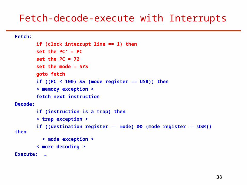
Fetch-decode-execute with Interrupts
Fetch:
if (clock interrupt line == 1) then
set the PC' = PC
set the PC = 72
set the mode = SYS
goto fetch
if ((PC < 100) && (mode register == USR)) then
< memory exception >
fetch next instruction
Decode:
if (instruction is a trap) then
< trap exception >
if ((destination register == mode) && (mode register == USR)) then
< mode exception >
< more decoding >
Execute: …

39
Entry Points
What are the "entry points" for our little example machine?
60: Memory access violation
64: Mode register violation
68: User-initiated trap
72: Clock interrupt
Each entry point is a jump to some code block in the OS
All real OS’es have a set of entry points for exceptions, traps, and interrupts
Sometimes they are combined and software has to figure out what happened.

40
Saving and Restoring Context
Recall the processor state:
PC, PC', R0-R31, mode register
When an entry to the OS happens, we want to start executing the correct routine (handler) then return to the user program such that it can continue executing normally
Can't just start using the registers in the OS!
Solution: save/restore the user context
Use the OS memory to save all the CPU state
Before returning to user, reload all the registers and then execute a return from exception instruction

41
Input and Output
How can humans get at the data?
How to load programs?
What happens if I turn the machine off?
Can I send the data to another machine?
Solution: add devices to perform these tasks
Keyboards, mice, graphics
Disk drives
Network cards

42
A Simple I/O Device: A Network Card
Network card has 2 registers:
A store into the “transmit” register sends the byte over the wire.
Transmit often is written as TX (E.g. TX register)
A load from the “receive” register reads the last byte that was read from the wire
Receive is often written as RX
How does the CPU access these registers?
Solution: map them into the memory space
An instruction that accesses memory cell 98 really accesses the transmit register instead of memory
An instruction that accesses memory cell 99 really accesses the receive register
These registers are said to be memory-mapped

43
Basic Network I/O
Clock
+,-,*,/+,-,*,/
CPU
88
PC'
Arithmetic Units
Logic Units <,>,!=<,>,!=
Registers 0-31
Mode register 00
Program Counter
Memory
Interrupt line
Reset line
0
Network card
9899
Transmit Reg.Transmit Reg.
Receive Reg.Receive Reg.

44
Why Memory-Mapped Registers
"Stealing" memory space for device registers has 2 functions:
Allows protected access --- only the OS can access the device.
User programs must trap into the OS to access I/O devices because of the normal protection mechanisms in the processor
Why do we want to prevent direct access to devices by user programs?
OS can control devices and move data to/from devices using regular load and store instructions
No changes to the instruction set are required
This is called programmed I/O

45
Status Registers
How does the OS know if a new byte has arrived?
How does the OS know when the last byte has been transmitted? (so it can send another one)
Solution: status registers
A status register holds the state of the last I/O operation
Our network card has 1 status registerTo transmit, the OS writes a byte into the TX register and sets bit 0 of the status register to 1. When the card has successfully transmitted the byte, it sets bit 0 of the status register back to 0.
When the card receives a byte, it puts the byte in the RX register and sets bit 1 of the status register to 1. After the OS reads this data, it sets bit 1 of the status register back to 0.

46
Polled I/O
To Transmit:
While (status register bit 0 == 1); // wait for card to be ready
TX register = data;
Status reg = status reg | 0x1; // tell card to TX (set bit 0 to 1)
Naïve Receive:
While (status register bit 1 != 1); // wait for data to arrive
Data = RX register;
Status reg = status reg & 0x01; // tell card got data (clear bit 1)
Can’t stall OS waiting to receive!
Solution: poll after the clock ticks
If (status register bit 1 == 1) {
Data = RX register
Status reg = status reg & 0x01;
}

47
Interrupt-driven I/O
Polling can waste many CPU cycles
On transmit, CPU slows to the speed of the device
Can't block on receive, so tie polling to clock, but wasted work if no RX data
Solution: use interrupts
When network has data to receive, signal an interrupt
When data is done transmitting, signal an interrupt

48
Polling vs. Interrupts
Why poll at all?
Interrupts have high overhead:
Stop processor
Figure out what caused interrupt
Save user state
Process request
Key factor is frequency of I/O vs. interrupt overhead

49
Direct Memory Access (DMA)
Problem with programmed I/O: CPU must load/store all the data from/into device registers.
The data is probably in memory anyway!
Solution: more hardware to allow the device to read and write memory just like the CPU
Base + bound or base + count registers in the device
Set base + count register
Set the start transmit register
I/O device reads memory from base
Interrupts when done

50
PIO vs. DMA
Overhead is lower for PIO than DMA
PIO is a check against the status register, then send or receive
DMA must set up the base, count, start transfer, take an interrupt
DMA is more efficient at moving data
PIO ties up the CPU for the entire length of the transfer
Size of the transfer becomes the key factor in when to use PIO vs. DMA

51
Example of PIO vs. DMA
Given:
A load costs 100 CPU “cycles” (time units)
A store costs 50 cycles
An interrupt costs 2000 instructions; each instruction takes 2 cycles
To send a packet via PIO costs 1 load + 1 store per byte
To send via DMA costs setup (4 stores) + interrupt
Find the packet size for which transmitting via DMA costs fewer CPU cycles than PIO

52
Example PIO vs. DMA
Find the number of bytes were PIO==DMA (cutoff point) cycles per load: L
cycles per store: S
bytes in the packet: B
Express simple equation for CPU cycles in terms of cost per byte: # of cycles for PIO = (L + S)*B
# of cycles for DMA = setup + interrupt
# of cycles for DMA = 4S + 4000
Set PIO cycles equal to DMA cycles and solve for bytes:
(L+S)*B = 4S+4000
(100+50)B = 4(50)+4000
B = 28 bytes (cutoff point)
When the packet size is >28 bytes, DMA costs less cycles than PIO.

53
Typical I/O Devices
Disk drives:
Present the CPU a linear array of fixed-sized blocks that are persistent across power cycles
Network cards:
Allow the CPU to send and receive discrete units of data (packets) across a wire, fiber or radio
Packet sizes 64-8000 bytes are typical
Graphics adapters:
Present the CPU with a memory that is turned into pixels on a screen

54
Recap: the I/O Design Space
Polling vs. interrupts
How does the device notify the processor an event happened?
Polling: Device is passive, CPU must read/write a register
Interrupt: Device signals CPU via an interrupt
Programmed I/O vs. DMA
How does the device send and receive data?
Programmed I/O: CPU must use load/store into the device
DMA: Device reads and writes memory

55
Practical: How to Boot?
How does a machine start running the operating system in the first place?
The process of starting the OS is called booting
Sequence of hardware + software events form the boot protocol
Boot protocol in modern machines is a 3-stage process
CPU starts executing from a fixed address
Firmware loads the boot loader
Boot loader loads the OS
56
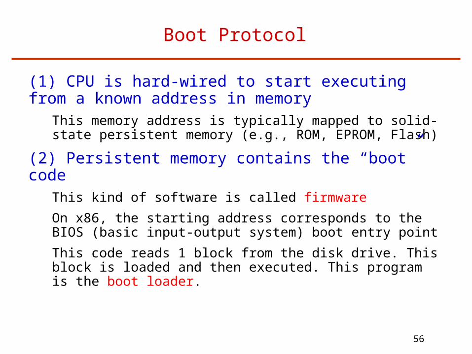
Boot Protocol
(1) CPU is hard-wired to start executing from a known address in memory
This memory address is typically mapped to solid-state persistent memory (e.g., ROM, EPROM, Flash)
(2) Persistent memory contains the “boot” codeThis kind of software is called firmware
On x86, the starting address corresponds to the BIOS (basic input-output system) boot entry point
This code reads 1 block from the disk drive. This block is loaded and then executed. This program is the boot loader.

57
Boot Protocol (cont)
(3) The boot loader can then load the rest of the operating system from disk. Note that at this point the OS still is not running
The boot loader can know about multiple operating systems
The boot loader can know about multiple versions of the OS
58
Why Have A Boot Protocol?
Why not just store the OS into persistent memory?
Separate the OS from the hardware
Multiple OSes or different versions of the OS
Want to boot from different devices
E.g. security via a network boot
OS is pretty big (tens of MBs). Rather not have it as firmware

59
Basic Computer Architecture
CPU Memory
memory bus
I/O bus
disk Net interface
Single-CPU-chip computer:• Single threaded• Multithreaded• Multi/many-core

60
Caching Inside A 4-Core CPU
Core Core Core Core
Private L1Caches
(coherence!)
Shared L2Cache
CPU

61
Multi-CPU-Chip Multiprocessors
CPUMemory
memory bus
I/O bus
disk Net interface
cache
Simple scheme (SMP): more than one CPU on the same bus Memory is shared among CPUs -- cache coherence between
LLCs Bus contention increases -- does not scale Alternative (non-bus) system interconnect -- complex and
expensive SMPs naturally support single-image operating systems
CPU
cache
Last level of hw caching

62
Cache-Coherent Shared-Memory: UMA
Core
Memory
Core Core Core
SnoopingCaches

63
CC-NUMA Multiprocessors
CPU Memory
memory bus
I/O bus
disk
cache
network
• Non-uniform access to different memories• Hardware allows remote memory accesses and maintains cache coherence• Scalable interconnect more scalable than bus-based UMA systems• Also naturally supports single-image operating systems• Complex hardware coherence protocols
MemCntrl
CPUMemory
memory bus
I/O bus
disk
cache
MemCntrl

64
Multicomputers
Network of computers: “share-nothing” -- cheap Distributed resources: difficult to program
Message passing Distributed file system
Challenge: build efficient global abstraction in software
CPUMemory
memory bus
I/O bus
disk Net interface
cache
CPUMemory
memory bus
I/O bus
diskNet interface
cache
network

65
Next Time
Processes