Embed Size (px)
Citation preview
An Architecture for Software Defined Cognitive Radio
Aveek Duttal, Dola Saha2, Dirk Grunwaldl,2, Douglas Sicker2 1 Department of Electrical , Computer and Energy Engineering
2Department of Computer Science University of Colorado
Boulder, CO 80309-0430 USA {Aveek.Dutta, Dola.Saha, Dirk.Grunwald, Douglas.Sicker}@colorado.edu
ABSTRACT
As we move forward towards the next generation of wireless pro
tocols, the push for a better radio physical layer is ever increasing.
Conventional radio architectures are limited to narrow operating
regions and fails to adapt with changing technology. This is fur
ther strengthened with the advent of cognitive radio, which needs a
more versatile and flexible framework that is programmable within
the timing constraints of a protocol. In this paper we present an
architecture for Software Defined Cognitive Radio that caters to the
specific baseband processing requirements in a changing environ
ment. We aim to provide more flexibility by de-constructing the
radio pipeline into a framework of user controlled kernels that can
be reconfigured at run-time. This architecture provides the bare
bones of a OFDM based radio physical layer that can adapt to per
form a varied number of tasks in different radio networks. We also
present a novel message based real-time reconfiguration method to
transmit and receive a wide range of waveforms used in concurrent
wireless protocols.
Categories and Subject Descriptors
C.O [GENERAL): Hardware/Software Interface; C.3 [SPECIAL
PURPOSE A ND APPLICATIO N-BASED SYSTEMS): Signal
Processing Systems; C.4 [PER FOR MA NCE O F SYSTEMS): Design Studies
General Terms
Design, Performance, Verification
Keywords
Cognitive Radio, NC-OFDM, Software Defined Radio, FPGA Im
plementation
1. INTRODUCTION Cognitive radios are an emerging wireless networking technol
ogy that are generally characterized as "reacting to an environment"
in order to improve network performance. Equally important, most
Permission to make digital or hard copies of all or part of this work for personal or classroom use is granted without fee provided that copies are not made or distributed for profit or commercial advantage and that copies bear this notice and the full citation on the first page. To copy otherwise, to republish, to post on servers or to redistribute to lists, requires prior specific permission and/or a fee. ANCS'1O, October 25-26, 2010, La Jolla, CA, USA. Copyright 2010 ACM 978-\-4503-0379-8/10/10 ... $10.00.
450 400 350
u 300 � .= 250 � 200
150 100 50
-40 -30 -20 -10 0 10 Frequency Subcarricrs
20 30
Figure 1: Spectrogram captured using a vector signal analyzer showing over-the-air transmission of multiple packets using non-contiguous O FDM from a SDCR transmitter. Packets are transmitted in a way to resemble the University of Colorado
at Boulder logo, using non-contiguous subsets of subcarriers ranging between [-27 and + 27]. The maximum possible signal bandwidth is 16.875M H z.
cognitive radios are envisioned to use Dynamic Spectrum Access (DSA) to make use of fractured available spectrum. A radio node
employing (DSA) acts as a secondary user and could use a part
of a licensed frequency band while causing no interference to the
primary user of that band. Orthogonal Frequency Division Multi
plexing (OFDM) multicarrier communication technique that allows
for such dynamic access of the medium. We discuss the applicabil
ity of OFDM in cognitive radio in more details in §3 and discuss
why this is a good choice for such an application. Thus a new
paradigm of non-contiguous spectrum access has evolved that has
led to cause radio hardware architecture to be more adaptive and
self aware to the ever changing radio environment. While transmis
sion in non-contiguous spectrum, often in multiple disjoint chunks
spread apart in frequency can be achieved with relative ease, re
ceiving such waveforms greatly complicates the tasks facing the
radio - for example: correlators, used to determine if a signal is in
transmission, now must look up across multiple bands instead on
one continuous range of frequencies [ 1 6].
A quick example of such a cognitive transmission is shown in
figure 1 . The spectrogram (x-axis represents frequency denoted
by OFDM subcarrier index and y-axis represents packet airtime),
shows how a cognitive transmitter adjusts it's tmnsmission band
width based on the available spectrum. The spectrogram is com
prised of hundreds of small packets transmitted over 450JLsec but
each packet occupies a different part of the spectrum denoted .by
the high spectral energies in dBm (red zones). The unoccupIed
spaces indicated by low spectral energy (green zones) coul� be
thought of as occupied by a primary user (not shown here) In a
licensed band and hence avoided by the cognitive mdio. This exam
ple shows how DSA coupled with OFDM is slowly �coming �e
choice for the next generation wireless networks. While transmIt
ting such waveforms is relatively easy, receiver functionality needs
to be redesigned considembly to support a non-contiguous spec
trum access. Thus, it is important to take a new look at the mdio
PHY and assess the requirements for next genemtion mdio archi
tecture. This paper discusses the challenges involved in designing
such radio PHY that is adaptable, fast and easy to reconfigure and
backward compatible with legacy systems using OFDM.
The evolution of processing for wireless networking, particularly
for Software Defined Cognitive Radios (SDCRs), is approaching a
design choice similar to Internet routers which has advanced sub
stantially over time. Network processors used two ways to speed
network processing. The first method, exemplified by the Intel
IXP processors, was to develop general purpose processors with
extensions and multiple specialized packet processing engines. Al
though those processors are intended for network processing tasks,
they can be used for other purposes (e.g. storage processing). An
other approach, adopted by systems such as the SiTerra/Vite�se
Prism processor accelerate specific steps of the network processIng
pipeline, such as implementing a specialized route lookup mech
anism. Recently, a generalized packet processing approach based
on the OpenFlow model has been proposed, leading to a rethinking
of forwarding hardware [8]. This model of forwarding uses more
general "match logic" (e.g. TCAMs) coupled with general purp?se
processors for populating that hardware. The same trend of USIng
a general purpose processor, followed by specialized hardware �d
then evolving into some general purpose processor coupled WIth
hardware accelemtion is common in many computing domains and
reflect both the increase in available silicon for special purpose ap
plications with analysis to determine the "kernel" of specific do
mains.
Radio processing on the other hand was originally digital hard
ware that was implemented using a combination of general purpose
DSPs or fixed-function logic implemented as an ASIC or using an
FPGA. Over time, specialized processor designs have evolved that
are finely tuned for handling a set of wireless protocols [27, 40].
However, these processors are mainly suitable for "3G" networks,
and it's not clear they are easily adaptable to "4G" or emerging ra
dio standards. Alternative architectures, such as the PicoChip pro
cessor [34] and other similar designs like SCA and XiRisc [1 0, 29] combine general purpose processors with fixed-function logic
designed to provide more efficient solutions to specific tasks (e.g. correlators for determining if a packet is being received). The most
challenging problem in the domain of cognitive radio is supporting
non-contiguous spectrum access while remaining backward com
patible and these architectures do not provide enough flexibility to
adopt this shifting pamdigm.
In this paper, we survey some of the techniques that we believe
cognitive radios will need to implement and highlight the impact of
those techniques on the underlying architecture. Our current imple
mentation is at the point of special purpose functional blocks im
plemented using an FPGA that form the foundation of 3G and 4G wireless protocols and are easily reconfigumble at run-time. The
contribution of this paper is a review of the structure of processing
steps needed in cognitive radios rather than a final general purpose
design for those processing steps.
2. RELATED WORK In this section, we discuss current research in the field of soft
ware defined radio for current wireless networks. Wireless protocol
processing can be broadly grouped into four categories: (1) So�t
ware processing only on general purpose processors, (2) On-chIp
network based architecture, (3) Multiprocessor architecture and (4)
Hybrid architecture - geneml purpose processors along with dedi
cated accelemtors using reconfigurable gate arrays.
When wireless PHY processing is done entirely in software as in
[1] and [3], although it aids in reprogramming using simple high
level programming languages, they often fail to meet the protocol
timing requirements for modern wireless protocols such as 802. 16 and other cognitive mdio protocols like 802.22 because of a com
bination of 110 throughput and post-processing using commercial
CPUs. The SORA platform [40], proposes a hybrid implemen
tation of 802.11 physical layer using general purpose CPUs and
a radio control board. Although most of the transceiver chain is
implemented in software, the system is currently not able to sup
port NC-OFDM transmission and reception, which is the basic n�
quirement for the cognitive mdio environment. SORA uses van
ous cache optimization techniques and core dedication for specific
functionalities, which might require redesigning for a wider band
width cognitive mdio.
NOC based processing [6, 22], relies heavily on the performance
of the routing algorithm and the efficiency of the common func
tional unit. Reprogmmming such devices can only be done at com
pile time. Unless, the functional units are multi-mode, supporting
multiple protocols is a challenge using this form of architecture.
Multiprocessor architectures are particularly effective for mdio
processing because it meets the protocol timing requirements in
most of the cases. SODA [27] provides a multi-processor architec
ture using optimized SIMD operations for digital processing, but
SODA fails to address the requirements for a SDCR and it is not
known if the processor could support non-contiguous OFDM pro
cessing. In [34], the authors propose a multiprocessor architecture
using several hundred processors. Implementation of mdio PHY
using highly parallel processors is shown in [1 2]. Researchers
have also used embedded processor to implement a simple single
carrier radio transceiver as in [5]. Processor based architectures are often complemented by dedi
cated hardware acceleration unit for particular algorithms. In [28, 34] employ FPGA accelemtors for DSP algorithms along with
RISC processors, where application specific functions can be
mapped. PicoArmy [34] is a tiled-processor architecture, contain
ing several hundred heterogeneous processors, connected through
a compile-time scheduled interconnect. These systems often com
bine dedicated hardware for correlations for signal detection.
Software controlled hardware is another form of processing en
gine that uses software to control certain "knobs" in the hardware
to perform multiple tasks. The WARP [31 ] and KUAR [21 ] are two
such platforms that are capable of certain cognitive mdio transmis
sion.
While most of the previous work focuses on architecture of the
actual processing engine, few focus on defining the requirements of a true cognitive radio. Therefore, instead of architecting just
software defined mdio, future research should be inclined towards
the idea of a software defined cognitive mdio. It is important to
envision how next genemtion wireless networks will behave, and
the design of the underlying hardware needs to be such that the
architecture is ready to embrace any adaptation required. In this paper, we present an architecture, which is capable of adapting in a cognitive radio environment and also allows for simple additions of newer functionality and tunable parameters.
3. OFDM FOR COGNITIVE RADIO Orthogonal Frequency Division Multiplexing (OFDM) [9] is a
special type of Multicarrier Modulation (MCM), where the data stream is divided into multiple bit streams and are modulated using closely spaced non-interfering frequencies called subcarriers. In conventional Frequency Division Multiplex (FDM) systems, a band-pass filter is used to filter to limit the bandwidth of the transmission or reception. In OFDM, instead of using sharp cut-off filters, an Inverse Fast Fourier Transform (FFT) is used to convert the frequency data carrying subcarriers to a time domains signal which can be upconverted to the desired carrier frequency. An inverse operation at the receiving using Fast Fourier Transform(FFf) reveals the frequency domain information. Establishing the correct symbol boundary is of utmost importance in any OFDM based system. Apart from the simple waveform generation and reconstruction, OFDM provides significant advantages over single carrier transmissions like : immunity to multipath distortion, scalability and spectral separation, making it a superior choice for large family of wireless protocols [30].
Cognitive Radio Networking is the next generation of wireless networks, where each radio is expected to sense the environment for available spectrum and adapt quickly to it without interfering with the incumbent for that carrier frequency. The secondary system should be able to avoid the primary transmission while communicating within its own network in a spectrum hole. This kind of network requires sensing capability, and fast adaptation to new frequency band for both transmission and reception. We believe that OFDM is likely to be chosen as the communication substrate in Cognitive Radio Networks due to its inherent capability of transmission and reception in variable bandwidth and in multiple chunks of subcarriers called subchannels without using any kind of bandpass filters. Any subcarrier set can be suppressed to form a NonContiguous OFDM (NC-OFDM) waveform, which can be utilized to transmit in a spectrum hole, avoiding the primary user. The use of FFT for OFDM also helps in sensing the spectrum, while other adaptation capabilities, like changing the number of subcarriers and subchannels makes OFDM the most appealing medium for communication in Cognitive Radio Networks. Since most of the newer protocols, like 802. 11, 802. 16, LTE, WRAN, WPAN, all use OFDM at the physical layer, we believe that OFDM is a likely choice for cognitive radio application. Table 1 shows some of these common OFDM parameters for three contemporary wireless protocols. This motivates our research in new architectures for software defined radios which will allow innovation in future deployments of cognitive radio networks.
Table 1: Common Transmission parameters
Parameter 802.1la/g 802.16 LTE
FFT Size 64 1 28,256, 1 024, 1 28,256,51 2, 2048, 4096 1 024,2048
CP size 1 /4 1 14, 1 /8, Variable 1 11 6, 1 /32
Bits/symbol 1 ,2,4,6 1 ,2,4,6 2,4,6 Pilots 4 Variable Variable
4. SDCR: REDEFINING THE RADIO PHY The similarity amongst different communication protocols is
also reflected in their corresponding physical layer. There is an increasing demand to redesign the common processing engines to perform most of the functions in a fast changing environment of cognitive radio. A close look at the current wireless protocols reveals that we can define a more fundamental set of operations or primitives, beyond just the the parameters or functional operation of a particular transceiver subsystem: e.g. , instead of having correlators with fixed coefficients, we should have a method to feed the coefficients required for a particular packet encoded using a particular protocol. This is typically required in a cognitive radio environment where the available spectrum varies over time and so does the number of available OFDM subcarriers which changes the time domain correlation coefficients [17, 33].
With various concurrent wireless protocols in mind we define a set of fundamental operations, a generic transceiver should have in order to operate as a SDCR. This de-construction of the radio physical layer beyond a multi-mode type operation is motivated by a substantial amount of prior research and publication in the cognitive radio community. We list the barebones of the transceiver and highlight the research that has motivated the design of this subsystem :
• SDCR should be able to transmit and receive in any set of subcarriers [24, 35, 17]. Essentially it should support noncontiguous OFDM transmission and reception.
• Not only does it need to adapt to changing spectrum availability, the SDCR should be able to change its modulation (e.g: BPSK, QPSK, 16QAM, 64QAM) at a subcarrier level. Also, high throughput wireless PRY layer techniques require advanced modulations such as superposition coding and hierarchical modulation, which require a high degree of programmability in the modulation levels. In [26, 38], we can find requirement of such systems.
• Depending on the availability of spectrum, the SDCR needs to change the FFT size to control the number of subcarriers to be used for the transmission. Also depending on the channel conditions the duration of the cyclic prefix needs to change to combat multipath channel distortions. WIMAX 802. 16 [24] and LTE [19] are examples of wireless protocols that directly requires this capability.
• In order to support NC-OFDM transmission, the SDCR receiver needs a programmable correlator which can support an arbitrary set of correlator coefficients from a pre-defined superset as chosen by the protocol. [42] and [7] are such examples that require synchronization of NC-OFDM preambles which changes the correlator co-efficients from one packet to another.
• Equalization is an important signal conditioning step used in the receivers. To accommodate with the changing environment, the transmitter selects different set of pilot subcarriers [1 1 , 24] to assist in the equalization at the receiver end. Therefore the pilot locations and their relevant phase is an important information that the receiver needs to have in order to equalize a NC-OFDM signal.
• Packets modulated using NCOFDM and with variable data rates for every subcarrier, the demodulator has to be programmable to be able to receive this type of transmission. In [35], we find the need for such a system with different demodulators across different subcarriers.
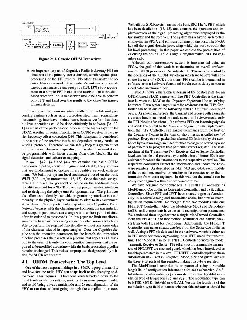
--------------------------------------- , : Transmitter -----n=-----, I 1 Encoded r Bit
I � ______________________________________ J
Figure 2: A Generic OFD M Transceiver
• An important aspect of Cognitive Radio is Sensing [41] for detection of the primary user a channel, which requires postprocessing of the FFT results. No other transmitter or receiver blocks are used in this mode. Recent works on simultaneous transmission and reception [15], [37] show requirement of a simple FFf block at the receiver and a threshold based detection. So, a transceiver should be able to perform only FFT and hand over the results to the Cognitive Engine to make decision.
In the above discussion we intentionally omit the bit-level processing engines such as error correction algorithms, scramblingdescrambling, interleave - deinterleave, because we find that these bit level operations could be done efficiently in software [36, 32, 1] as a part of the packetization process in the higher layer of the SOCR. Another important function in an OFDM receiver is the carrier frequency offset correction [39]. This subsystem is considered to be a part of the receiver that is not dependent on any particular wireless protocol. Therefore, we can safely keep this system out of our discussion. However, depending on the algorithm used it can be programmable with inputs coming from other blocks like the signal detection and subcarrier mapping.
In §4. 1, §4.2, §4.3 and §4.4 we examine the basic OFDM transceiver pipeline, shown in Figure 2 and identify the primitives that are fundamental to operate in a cognitive network environment. We build our system level architecture based on the basic Wi-Fi (802.11a/ g) transceiver [18, 13]. Once the basic subsystems are in place, we go about to decide on the additional functionality required for a SOCR by adding programmable interfaces and re-designing the subsystems for optimum use. The primitives also allow us to identify a suitable programming interface that can reconfigure the physical layer hardware to adapt to its environment at run-time. This is particularly important in a Cognitive Radio Network because with the changing environment, the transmission and reception parameters can change within a short period of time, often in order of microseconds. In this paper we limit our discussion to the baseband processing elements called kernels which are able to perform the required functionality without any knowledge of the characteristics of its input samples. Once the Cognitive En
gine sets the operation parameters for the kernels the transceiver pipeline processes the packets as a pipeline that appears as a black box to the user. It is only the configuration parameters that are required to be modified at runtime while the basic processing pipeline remains unchanged. This makes our proposed design specially suitable for SOCR architecture.
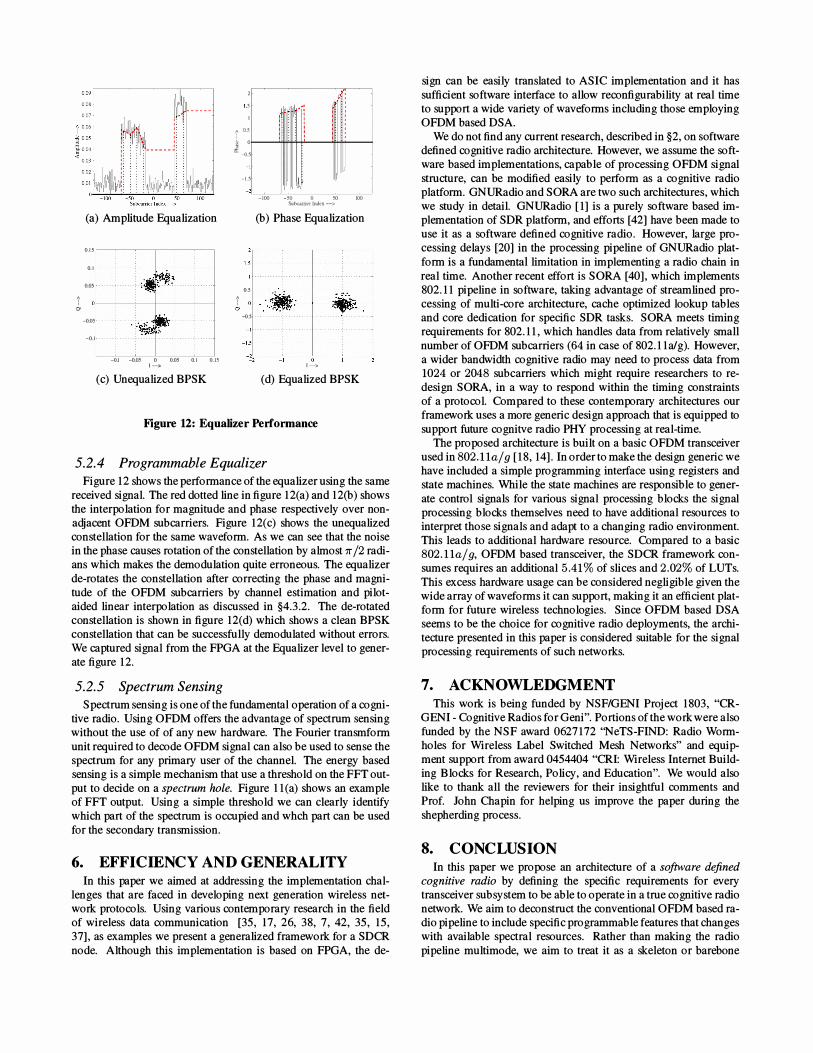
4.1 OF DM Transceiver : The Top Level One of the most important things in a SOCR is programmability
and how fast the radio PHY can adapt itself to the changing environment. This requires: 1) barebone kernels broken down to the most fundamental operations, making them more programmable and avoid being always multimode and 2) reconfiguration of the PHY at run-time without going through the compilation process.
We built our SOCR system on top of a basic 802.11a/ 9 PHY which has been detailed in [18, 13], and contains the operation and implementation of the signal processing algorithms employed in the transmitter and the receiver. The system has a hybrid architecture employing an FPGA and software running on the host. The FPGA has all the signal domain processing while the host controls the bit-level processing. In this paper we explore the possibilities of extending the basic PHY to a highly programmable PHY for cognitive radio.
Although our representative system is implemented using an FPGA, the goal of this work is to determine an overall architec
ture for SOCR processors. As indicated, FFf kernels are central to the operation of the OFDM waveform which we believe will constitute the core of SOCR algorithms. FFTs can be implemented in software or in a hardware functional block; our initial system uses a dedicated hardware block.
Figure 3 shows a hierarchical design of the control path for an OFDM based SOCR transceiver. The PHY Controller is the interface between the MAC or the Cognitive Engine and the underlying hardware. For a typical cognitive radio environment the PHY Controller can be in one of the following states : Transmit, Receive or Sense. As shown in Figure 2, the transmit and receive path elements are made functional based on mode selection. In Sense mode, only the FFT block is functional. It performs FFTs on incoming signals and sends the output to the Cognitive Engine. In our implementation, the PHY Controller can handle commands from the host or the Cognitive Engine in the form of short messages called control
packets. Every control packet has a kernel ID followed by the number of bytes of message included for that message, followed by a set of parameters to program that particular kernel register. The state machine at the Transmitter(Tx), Receiver(Rx) or Sense Controller level can decode and process any combination of kernel IDs in any order and forwards the information to the respective controller. The respective controllers extract the information and update the hardware registers. As described in §4.2, §4.3 and §4.4, each module of the transmitter, receiver or sensing mode operates using the information from these registers. In this way the the kernels can be easily reconfigured within a short period of time.
We have designed four controllers, a) FFfIIFFT Controller, b) Mod/Demod Controller, c) Correlator Controller, and d) Equalizer Controller. Since FFf and IFFf have exactly opposite functionality in receiver/sensing and transmitter chain, but similar reconfiguration requirements, we merged these two modules into one FFTIIFFT Controller. Also, the Modulator(Mod) and Demodulator(Demod) components have the same reconfiguration parameters. We combined these together into a single Mod/Demod Controller. Both the FFT/IFFf and modldemod controllers can handle packets from both Tx and Rx Controllers. Additionally, the FFfIIFFT Controller can parse control packets from the Sense Controller as well. A single FFf block is used in the hardware, which is either set in FFf mode for receiving/sensing, or in IFFf mode for transmitting. The "Mode ID" in the FFTIIFFT Controller denotes the mode: Transmit, Receive or Sense. The other two programmable parameters of FFTIIFFT are size and guard, which has been introduced as tunable parameters in this level. FFTIIFFT Controller updates these information in FFTIlFFT Register. Mode, size and guard size are the three 8-bit parts of this register, making it a 3-byte register.
The ModlDemod controller is programmed using a variable length list of configuration information for each subcarrier. An 8-bit subcarrier information (Pi) is inserted, followed by 4-bit modulation type of frequencies Pi and PH1. The modulation type can be BPSK, QPSK, 16QAM or 64QAM. We use the fourth bit of the modulation type field to denote whether this subcarrier should be
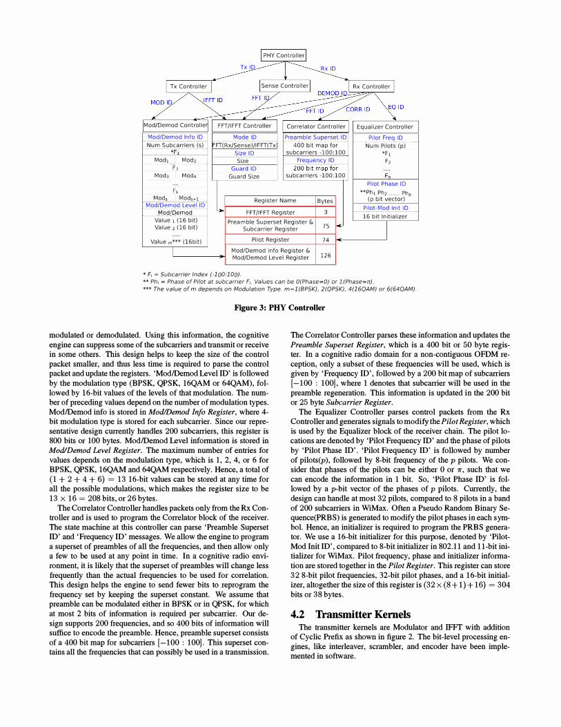
I PHY Controller I Tx lO Rx 10
I Tx Controller I Sense Controller I I Rx Controller I �FTIO FFTy �OO ln
7 O �IO
Mod/Oemod Control Ie FFT/IFFT Controller Correlator Controller Equalizer Controller Mod/Oemod Info 10 Num Subcarriers (s) " ' :"fi.:: ' "
Mod, i Mod, --------------·+Ji����������������
Mod3 i Mod.
F,
Mode 10 FT(Rx/Sense)/IFFT(Tx
Size 10 Size
Guard 10 . Guard size'"
Preamble Superset 10 ·····400·t;(t·map·fc;r····· subcarriers -100:100
Frequency 10 200bit'mapfor
subcarriers -100:100
Pilot Freq 10 ······r;.i,:im·piiots·(py·_·
*h F,
Fo Pilot Phase 10
**Ph, Ph, ...... Php Mods i Mods+l Register Name Bytes Mod/Oemod Level 10
(p bit vector)
........ �9.�!.I?��9.� ......... .. FFT/IFFT Register 3 Pilot-Mod Init 10 16 bit Initializer Value 1 (16 bit) Preamble Superset Register & 75 •
I Value, (16 bit) Subcarrier Register
Value m*** (16bit) Pilot Register 74
I Mod/Demod Info Register & 126 Mod/Oemod Level Register
* F; = Subcarrier Index (-100:100).
** Ph; = Phase of Pilot at subcarrier F;. Values can be O(Phase=O) or 1 (Phase=rr).
*** The value of m depends on Modulation Type. m=l(BPSK), 2(QPSK), 4(16QAM) or 6(64QAM).
Figure 3: PRY Controller
modulated or demodulated. Using this information, the cognitive engine can suppress some of the subcarriers and transmit or receive in some others. This design helps to keep the size of the control packet smaller, and thus less time is required to parse the control packet and update the registers. 'ModlDemod Level ID' is followed by the modulation type (BPSK, QPSK, 16QAM or 64QAM), followed by 16-bit values of the levels of that modulation. The number of preceding values depend on the number of modulation types. ModlDemod info is stored in ModlDemod Info Register, where 4-bit modulation type is stored for each subcarrier. Since our representative design currently handles 200 subcarriers, this register is 800 bits or 100 bytes. ModlDemod Level information is stored in ModiDemod Level Register. The maximum number of entries for values depends on the modulation type, which is 1 , 2, 4, or 6 for BPSK, QPSK, 16QAM and 64QAM respectively. Hence, a total of (1 + 2 + 4 + 6) = 13 16-bit values can be stored at any time for all the possible modulations, which makes the register size to be 13 x 16 = 208 bits, or 26 bytes.
The Correlator Controller handles packets only from the Rx Controller and is used to program the Correlator block of the receiver. The state machine at this controller can parse 'Preamble Superset ID' and 'Frequency ID' messages. We allow the engine to program a superset of preambles of all the frequencies, and then allow only a few to be used at any point in time. In a cognitive radio environment, it is likely that the superset of preambles will change less frequently than the actual frequencies to be used for correlation. This design helps the engine to send fewer bits to reprogram the frequency set by keeping the superset constant. We assume that preamble can be modulated either in BPSK or in QPSK, for which at most 2 bits of information is required per subcarrier. Our design supports 200 frequencies, and so 400 bits of information will suffice to encode the preamble. Hence, preamble superset consists of a 400 bit map for subcarriers [-100 : 1001. This superset contains all the frequencies that can possibly be used in a transmission.
The Correlator Controller parses these information and updates the Preamble Superset Register, which is a 400 bit or 50 byte register. In a cognitive radio domain for a non-contiguous OFDM reception, only a subset of these frequencies will be used, which is given by 'Frequency ID', followed by a 200 bit map of subcarriers [- 100 : 1001, where 1 denotes that subcarrier will be used in the preamble regeneration. This information is updated in the 200 bit or 25 byte Subcarrier Register.
The Equalizer Controller parses control packets from the Rx Controller and generates signals to modify the Pilot Register, which is used by the Equalizer block of the receiver chain. The pilot locations are denoted by 'Pilot Frequency ID' and the phase of pilots by 'Pilot Phase ID'. 'Pilot Frequency ID' is followed by number of pilots(p), followed by 8-bit frequency of the p pilots. We consider that phases of the pilots can be either 0 or 11', such that we can encode the information in 1 bit. So, 'Pilot Phase ID' is followed by a p-bit vector of the phases of p pilots. Currently, the design can handle at most 32 pilots, compared to 8 pilots in a band of 200 subcarriers in WiMax. Often a Pseudo Random Binary Sequence(PRBS) is generated to modify the pilot phases in each symbol. Hence, an initializer is required to program the PRBS generator. We use a 16-bit initializer for this purpose, denoted by 'PilotMod Init ID', compared to 8-bit initializer in 802.1 1 and II-bit initializer for WiMax. Pilot frequency, phase and initializer information are stored together in the Pilot Register. This register can store 32 8-bit pilot frequencies, 32-bit pilot phases, and a 1 6-bit initializer, altogether the size of this register is (32 x (8 + 1) + 16) = 304 bits or 38 bytes.
4.2 Transmitter Kernels The transmitter kernels are Modulator and IFFT with addition
of Cyclic Prefix as shown in figure 2. The bit-level processing engines, like interleaver, scrambler, and encoder have been implemented in software.
Mode FR (Tx. Rx or Sense)
From Mod (Tx) .. From Pkt Select
Detect (Rx) Input
§] Size t
IFFT(Tx) or
� G��:Ut To DAC (Tx) Add CP (Tx) Select or Output To �ualizer (Rx)
From ADC .. Line Samples FFT Samples Remove CP Samples Line In To Cognitive I (Rx. Sense) Out (Rx) Out .. (Sense)
i t Engine (Sense)
FFT Start rfRl FFT/IFFT Register-� stores Mode (Tx. Rx or Sense). Size of FFT/IFFT and Size of Cyclic Prefix
Figure 5: Programmable FIT or ( FIT Block
Coded Bits from Coder
��M� o>.c(d_��-�-:I X (k) Levels 1---'-""-"--___. To
Per Subcarrier XO(k) IFFT
Mod Info
Subcarrier Count
I M/DLRIMad/Demod Level Registerstares the levels far mod ar demad
I M/DIR I Mad/Demad Info Register-stores the mad ar demad infa far each subcarrier
Figure 4: Programmable Modulator Block
4.2.1 Modulator
The modulator is one of the programmable units implemented in the FPGA, that uses the information in 'ModlDemod Info Register' and 'ModIDemod Level Register'. Figure 4 shows a block diagram of the programmable modulator. A modulator block intakes coded bits and modulates them into complex samples of I and Q values, depending on the modulation type and modulation level. Advanced communication protocols such as Superposition Coding [26] and Hierarchical Encoding [38] techniques need different levels of modulation; this is implemented by having a "constellation mapping" table that is programmable rather than using fixed values as in a convention transceiver design. The constellation mapping is performed for each subcarrier. So, based on the Subcarrier Count, which is another input of the modulation block, the modulation type for that subcarrier is fetched from the 'ModlDemod Info Register'. Based on this modulation type, the level for constellation mapping is fetched from 'ModlDemod Level Register'. Then number of coded bits to be modulated is selected based on the modulation type, which can be 1 , 2, 4 or 6 for BPSK, QPSK, 16QAM and 64QAM respectively. Based on these information, the I and Q values are generated by the Constellation Mapping block, which are fed into IFFT. If the 4th bit of modulation type is set to 0 for any subcarrier, it indicates that this subcarrier will not be transmitted, and the Constellation Mapping block outputs 0 values for both I and Q samples.
4.2.2 Inverse Fourier Transform
After the bits are modulated into complex samples, they enter a common programmable FFTIIFFT kernel, used as transmitter, receiver or sensing mode. Figure 5 shows a block diagram of this generic platform and in this section, we will discuss how this block can be programmed for transmitter mode. The kernel uses information from 'FFT/IFFT Register' to get the mode. If the mode is set to transmitter, the Modulator output is selected as the input of the
IFFT. Also, the FFTIIFFT block is set to IFFT mode. Based on the size information available in the register, the size of IFFT is chosen. Then, IFFT is performed on the modulator output. In transmitter, based on the Guard Size, the Cyclic Prefix is added to the samples. Finally, depending on the mode, output line is selected. For transmitter, samples are sent out to Digital to Analog Converters(DACs) which are connected to the frontend radio.
4.3 Receiver Kernels The receiver subsystems as shown in Figure 2 comprises of: Syn
chronizer or Packet Detect, FFT and Guard Removal, Equalizer and Demodulator. Apart from this there are other bit-level processing engines like de-interleaver, FEC decoder, CRC check and de-packetization to extract the information bits in the packet. As in the transmitter we exclude the bit-level processing from our design since they are efficiently performed in software at the host. §4.1 describes the control bits required to program all the kernels in the receiver. In this section we delve into the details of how the control bits are used to modify the kernels with changing environment.
4.3.1 Synchronizer and Packet Detect
The Synchronizer or the Packet Detect kernel is the entry point of the baseband receiver. The primary job of the Synchronizer is to identify the boundary of a valid OFDM symbol. This is particularly important because it introduces phase noise into the signal which in turn makes the frequency domain decoding erroneous. In an OFDM based system, synchronization is typically done using a time domain correlation which searches for a pre-defined pattern called the preamble. Since in OFDM, the preamble is constructed and encoded in the frequency domain [23, 25], the time domain samples changes significantly with the encoding process, i.e., if the transmitter chooses to suppress a set of subcarriers then those subcarriers are not used to transmit the preamble. This makes the preamble quite different from the conventional preambles in wireless protocols that typically uses all the subcarriers supported by the protocol. Furthermore, the frequency domain data for the preamble varies from one protocol to the other. But fortunately they all employ the same basic technique to acquire synchronization.
Therefore, due to the non-contiguous modulation of the preamble and the variable nature of the frequency domain encoding, it is required to have a programmable Synchronizer. The time-domain Correlator employs a running comparison with a local copy of the time-domain samples of the preamble being searched. Typically, the Correlator size is of 64 samples. But depending on the sampling frequency and the FFT size this may vary. The basic operation in a Correlator is shift-multiply-accumulate for every fixed-point complex sample in the Correlator block. As the size of the Correlator increases in our design to 256 with increasing FFT size, the number of multipliers and adders increases significantly to make the
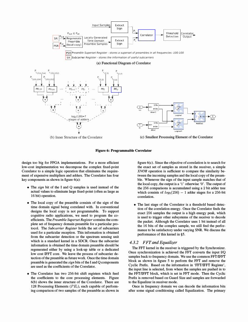
Psub � Pall
Input Sample,;
Locally Generated Time Domain
Preamble Samples
Correlator Output
� preamble Superset Register· stores a superset of preambles in all frequencies ·100:100 �Subcarrier Register· stores the information of useful subcarriers
(a) Functional Diagram of Correlator
P P l(255254) L[253.252)
PI [255,254) PI [253,252 I
-t- L I PEi+l I 1- r _ J
I I
_t_ j_ I PE; I .... 1- _ T J
---t.f-" ::l)
log,(128)=7 , ,�tages of adder� / /
P P l12,3) L 1.0J P'".3) P,Ii.O)
---t.f-" ', + : '/
(b) Inner Structme of the Conelator (c) Smallest Processing Element of the Correlator
Figure 6: Programmable Correia tor
design too big for FPGA implementations. For a more efficient low-cost implementation we decompose the complex fixed-point Correlator to a simple logic operation that eliminates the requirement of expensive multipliers and adders. The Correlator has fom key components as shown in figure 6(a):
• The sign bit of the I and Q samples is used instead of the actual values to eliminate large fixed-point (often as large as 16 bit) operation.
• The local copy of the preamble consists of the sign of the time domain signal being correlated with. In conventional designs the local copy is not programmable. To support cognitive radio applications, we need to program the coefficients. The Preamble Superset Register contains the complete set of frequency domain preamble for a particular protocoL The Subcarrier Register holds the set of subcarriers used for a particular reception. This information is obtained from the subcarrier detection or the spectrum sensing unit which is a standard kernel in a SDCR. Once the subcarrier information is obtained the time domain preamble should be regenerated either by using a look-up table or a dedicated low cost IFFT core. We leave the process of subcarrier detection of the preamble as futme work. Once the time domain preamble is generated the sign bits of the I and Q components are used as the coefficients of the Correlator.
• The Correlator has two 256-bit shift registers which feed the coefficients to the core processing elements. Figure 6(b) shows the inner structme of the Correlator. There are 128 Processing Elements (P Ei), each capable of performing comparison of two samples of the preamble as shown in
figure 6(c). Since the objective of correlation is to search for the exact set of samples as stored in the receiver, a simple XNOR operation is sufficient to compare the similarity between the incoming samples and the local copy of the preamble. Whenever the sign of the input sample matches that of the local copy, the output is a T otherwise '0'. The output of the 256 comparisons is accumulated using a 2 bit adder tree which consists of [092(256) - 1 adder stages for a 256-bit correlation,
• The last stage of the Correlator is a threshold based detection of the correlation energy. Once the Correlator finds the exact 256 samples the output is a high energy peak, which is used to trigger other subsystems of the receiver to decode the packet. Although the Correlator uses 1 bit instead of all the 16 bits of the complex sample, we still find the performance to be satisfactory under varying SNR. We discuss the performance of this kernel in §5.
4.3.2 FFT and Equalizer
The FFT kernel in the receiver is triggered by the Synchronizer. Once synchronization is achieved the FFT converts the input I1Q samples back to frequency domain. We use the common FFTIIFFT block as shown in figure 5 to perform the FFT and remove the Cyclic Prefix. Based on the information in 'FFT/IFFT Register', the input line is selected, from where the samples are pushed in to the FFTIIFFT block, which is set in FFT mode. Then the Cyclic Prefix is removed based on Guard Size and samples are forwarded to the Equalizer in receiver mode.
Once in frequency domain we can decode the information bits after some signal conditioning called Equalization. The primary
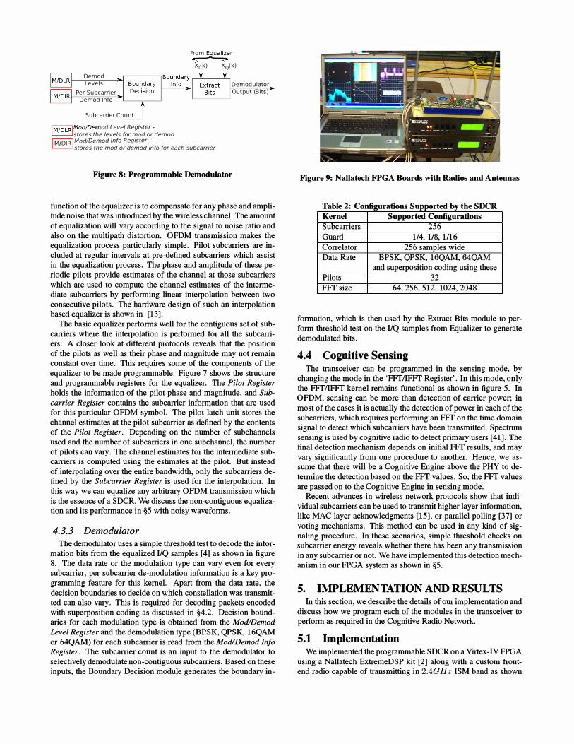
Demod Levels
Per Subcarrier Demod Info
Subcarrier Count
I M /DLR IModloemod Level Register·
From E�ualizer -I\. ",-
X1(k) XQ(k)
Demodulator Output (Bits)
stores the levels for mod or demod I M/DIR I ModlOemod Info Register·
stores the mod or demod info for each subcarrier
Figure 8: Programmable Demodulator
function of the equalizer is to compensate for any phase and amplitude noise that was introduced by the wireless channel. The amount of equalization will vary according to the signal to noise ratio and also on the multi path distortion. OFDM transmission makes the equalization process particularly simple. Pilot subcarriers are included at regular intervals at pre-defined subcarriers which assist in the equalization process. The phase and amplitude of these periodic pilots provide estimates of the channel at those subcarriers which are used to compute the channel estimates of the intermediate subcarriers by performing linear interpolation between two consecutive pilots. The hardware design of such an interpolation based equalizer is shown in [13].
The basic equalizer performs well for the contiguous set of subcarriers where the interpolation is performed for all the subcarriers. A closer look at different protocols reveals that the position of the pilots as well as their phase and magnitude may not remain constant over time. This requires some of the components of the equalizer to be made programmable. Figure 7 shows the structure and programmable registers for the equalizer. The Pilot Register
holds the information of the pilot phase and magnitude, and Sub
carrier Register contains the subcarrier information that are used for this particular OFDM symbol. The pilot latch unit stores the channel estimates at the pilot subcarrier as defined by the contents of the Pilot Register. Depending on the number of subchannels used and the number of subcarriers in one subchannel, the number of pilots can vary. The channel estimates for the intermediate subcarriers is computed using the estimates at the pilot. But instead of interpolating over the entire bandwidth, only the subcarriers defined by the Subcarrier Register is used for the interpolation. In this way we can equalize any arbitrary OFDM transmission which is the essence of a SDCR. We discuss the non-contiguous equalization and its performance in §5 with noisy waveforms.
4.3.3 Demodulator
The demodulator uses a simple threshold test to decode the information bits from the equalized I1Q samples [4] as shown in figure 8. The data rate or the modulation type can vary even for every subcarrier; per subcarrier de-modulation information is a key programming feature for this kernel. Apart from the data rate, the decision boundaries to decide on which constellation was transmitted can also vary. This is required for decoding packets encoded with superposition coding as discussed in §4.2. Decision boundaries for each modulation type is obtained from the ModlDemod
Level Register and the demodulation type (BPSK, QPSK, 16QAM or 64QAM) for each subcarrier is read from the ModiDemod Info Register. The subcarrier count is an input to the demodulator to selectively demodulate non-contiguous subcarriers. Based on these inputs, the Boundary Decision module generates the boundary in-
Figure 9: Nallatech FPGA Boards with Radios and Antennas
Table 2: Configurations Supported by the SDCR
Kernel Supported Configurations
Subcarriers 256 Guard 114, 1/8, 1116 Correlator 256 samples wide Data Rate BPSK, QPSK, 16QAM, 64QAM
and superposition coding using these Pilots 32 FFT size 64, 256, 512, 1024, 2048
formation, which is then used by the Extract Bits module to perform threshold test on the I1Q samples from Equalizer to generate demodulated bits.
4.4 Cognitive Sensing The transceiver can be programmed in the sensing mode, by
changing the mode in the 'FFfIIFFT Register'. In this mode, only the FFfIIFFT kernel remains functional as shown in figure 5. In OFDM, sensing can be more than detection of carrier power; in most of the cases it is actually the detection of power in each of the subcarriers, which requires performing an FFT on the time domain signal to detect which subcarriers have been transmitted. Spectrum sensing is used by cognitive radio to detect primary users [41]. The final detection mechanism depends on initial FFf results, and may vary significantly from one procedure to another. Hence, we assume that there will be a Cognitive Engine above the PHY to determine the detection based on the FFf values. So, the FFT values are passed on to the Cognitive Engine in sensing mode.
Recent advances in wireless network protocols show that individual subcarriers can be used to transmit higher layer information, like MAC layer acknowledgments [15], or parallel polling [37] or voting mechanisms. This method can be used in any kind of signaling procedure. In these scenarios, simple threshold checks on subcarrier energy reveals whether there has been any transmission in any subcarrier or not. We have implemented this detection mechanism in our FPGA system as shown in §5.
5. IMPLEMENTATION AND RESULTS In this section, we describe the details of our implementation and
discuss how we program each of the modules in the transceiver to perform as required in the Cognitive Radio Network.
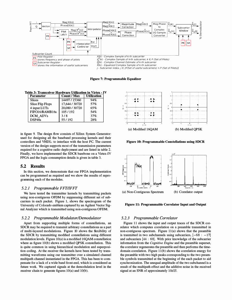
5.1 Implementation We implemented the programmable SDCR on a Virtex-IV FPGA
using a Nallatech ExtremeDSP kit [2] along with a custom frontend radio capable of transmitting in 2.4G H z ISM band as shown
I- � tt Mag-Phase B � E to :> � Complex "0 0
I/O Sample E Q) Converter 0
1'2
Subcarrier Count r;;Rl Pilot Register -� stores frequency and phase of pilots rsRl Subcarrier Register -
XW) - Complex Samp e a -t su carner X (k) - Complex Sample of k-th subcarrier, k E P (Set of Pilots) {irk) - Complex Channel Estimate of k-th subcarrier )((k) - Equalized Complex Sample of k-th subcarrier � stores the information of useful subcarriers j - Subcarrier index, j E [F(Set of useful sub carriers) n P (Set of Pilots)]
Figure 7: Programmable EquaUzer
Table 3' Transceiver Hardware Utilization in Virtex - IV Parameter Count / Max Utilization
Slices 14497 / 15360 94% Slice Flip Flops 17,644 / 30720 57% 4 input LUTs 20,080 / 30720 65% FIF016lRAMB 1 6s 1 05 / 192 54% DCM_ADVs 3 / 8 37% DSP48s 55 / 192 28%
in figure 9. The design flow consists of Xilinx System Generator: used for designing all the baseband processing kernels and their controllers and VHDL: to interface with the host Pc. The current version of the design supports most of the transmission parameters required for a cognitive radio deployment and are listed in table 2. Finally, we have implemented the SDCR barebone on a Virtex-IV FPGA and the logic consumption details is given in table 3.
5.2 Results In this section, we demonstrate that our FPGA implementation
can be programmed as required and we show the results of reprogramming each of the modules.
5.2.1 Programmable FFT/IFFT
We have tested the transmitter kernels by transmitting packets using non-contiguous OFDM by suppressing different set of subcarriers in each packet. Figure 1 , shows the spectrogram of the University of Colorado emblem captured by an Agilent Vector Signal Analyzer which is transmitted using non-contiguous OFDM.
5.2.2 Programmable Modulator/Demodulator
Apart from supporting multiple forms of constellations, an SDCR may be required to transmit arbitrary constellations as a part of multi-layered modulations. Figure 10 shows the flexibility of the SDCR by transmitting modified constellations using different modulation levels. Figure 1O(a) is a modified l6QAM constellation where as figure 1O(b) shows a modified QPSK constellation. This is quite common in using hierarchical modulation and superposition coding. At the receiver the kernels have been tested by transmitting waveforms using our transmitter over a simulated channel multipath channel instantiated in the FPGA. This has been to compensate for a lack of a wide band front-end, which is considered as future work. We captured signals at the demodulation level in the receiver chain to generate figures lO(a) and lO(b).
1.S .. . . . . ... 11 . . . . .
" . 1 ·
0. 5 .. : 0 : '" -0.5 " · . . . . · · i· ·
- 1 " . . . . ... ... . . -1 .5 . . . . . . . . - • . - .
--2 - 1 o 1 ->
. . . .. , .. . . . . .. �
• ; . . . . . 1-. . . .. ... . . .
(a) Modified 16QAM
O.S
-1 -1 .S
--2 -1 o 1 -->
(b) Modified QPSK
Figure 10: Programmable Constellations using SDCR
1 .2 ,.S
(a) Non-Contiguous Spectrum
:r. lO·
4()() 600 800 1000 Samples -> (b) Correlator output
Figure 11: Programmable Correlator Input and Output
5.2.3 Programmable Correlator Figure 1 1 shows the input and output traces of the SDCR cor
relator which computes correlation on a preamble transmitted in non-contiguous spectrum. Figure l 1 (a) shows that the preamble is tranmitted in two subchannels using subcarriers, [-68 : - 171 and subcarriers [44 : 691 . With prior knowledge of the subcarrier information from the Cognitive Engine and the preamble superset, the correlator regenerates the preamble and then performs the timedomain correlation. Figure 1 1 (b) shows the correlation energy for the preamble with two high peaks corresponding to the two preamble symbols transmitted at the beginning of the each packet to aid synchronization, The unequal amplitude of the two subchannel is a result of the multi path effect and the additive noise in the received signal at an SNR of approximately lOdB.
i 0
(a) Amplitude Equalization
0. 1 5 0. 1
0.05
-0.05 -0.1
. ' . . tf!.#� " " .
. : .. >:,� ':.if ... ..
-0.1 -0.(1'5 0 0.05 0. 1 0 . 15 1 -> (c) Unequalized BPSK
2 , . . , � . " 1 ! ! l 11 , I � !
� ; l' o.
0 , � -<J
1
- I ,
Ll
-
II � I : i
� 100 50 0 50 100 Subcarricr lndcx -> (b) Phase Equalization
0.5 • • '_ : i O��+-: -l--f;�\-
CI • ••• � "Y"-- . -<J'
- '
-
: 1 -�'!;--2 -----';-_I-----cOC----:--� 1 ->
(d) Equalized BPSK
Figure 12: Equalizer Performance
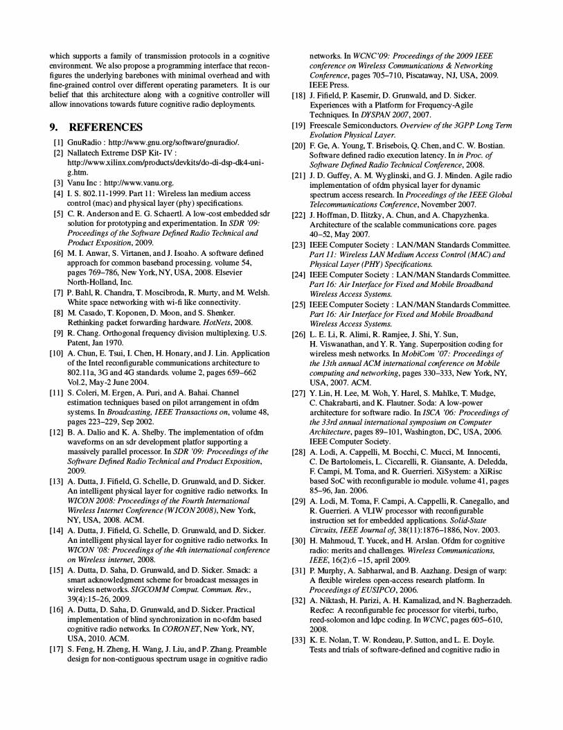
5.2.4 Programmable Equalizer Figure 1 2 shows the performance of the equalizer using the same
received signal. The red dotted line in figure 1 2(a) and 1 2(b) shows the interpolation for magnitude and phase respectively over nonadjacent OFDM subcarriers. Figure 1 2(c) shows the unequalized constellation for the same waveform. As we can see that the noise in the phase causes rotation of the constellation by almost 7r /2 radians which makes the demodulation quite erroneous. The equalizer de-rotates the constellation after correcting the phase and magnitude of the OFDM subcarriers by channel estimation and pilotaided linear interpolation as discussed in §4.3.2. The de-rotated constellation is shown in figure 1 2(d) which shows a clean BPSK constellation that can be successfully demodulated without errors. We captured signal from the FPGA at the Equalizer level to generate figure 1 2.
5.2. 5 Spectrum Sensing Spectrum sensing is one of the fundamental operation of a cogni
tive radio. Using OFDM offers the advantage of spectrum sensing without the use of of any new hardware. The Fourier transmform unit required to decode OFDM signal can also be used to sense the spectrum for any primary user of the channel. The energy based sensing is a simple mechanism that use a threshold on the FFT output to decide on a spectrum hole. Figure I l (a) shows an example of FFT output. Using a simple threshold we can clearly identify which part of the spectrum is occupied and whch part can be used for the secondary transmission.
6. EFFICIENCY AND GENERALITY In this paper we aimed at addressing the implementation chal
lenges that are faced in developing next generation wireless network protocols. Using various contemporary research in the field of wireless data communication [35, 17, 26, 38, 7, 42, 35, 1 5, 37], as examples we present a generalized framework for a SDCR node. Although this implementation is based on FPGA, the de-
sign can be easily translated to ASIC implementation and it has sufficient software interface to allow reconfigurability at real time to support a wide variety of waveforms including those employing OFDM based DSA.
We do not find any current research, described in §2, on software defined cognitive radio architecture. However, we assume the software based implementations, capable of processing OFDM signal structure, can be modified easily to perform as a cognitive radio platform. GNURadio and SORA are two such architectures, which we study in detail. GNURadio [1] is a purely software based implementation of SDR platform, and efforts [42] have been made to use it as a software defined cognitive radio. However, large processing delays [20] in the processing pipeline of GNURadio platform is a fundamental limitation in implementing a radio chain in real time. Another recent effort is SORA [40], which implements 802. 1 1 pipeline in software, taking advantage of streamlined processing of multi-core architecture, cache optimized lookup tables and core dedication for specific SDR tasks. SORA meets timing requirements for 802. 1 1 , which handles data from relatively small number of OFDM subcarriers (64 in case of 802. I l a/g). However, a wider bandwidth cognitive radio may need to process data from 1024 or 2048 subcarriers which might require researchers to redesign SORA, in a way to respond within the timing constraints of a protocol. Compared to these contemporary architectures our framework uses a more generic design approach that is equipped to support future cognitve radio PHY processing at real-time.
The proposed architecture is built on a basic OFDM transceiver used in 802.11a/ g [1 8, 1 4]. In order to make the design generic we have included a simple programming interface using registers and state machines. While the state machines are responsible to generate control signals for various signal processing blocks the signal processing blocks themselves need to have additional resources to interpret those signals and adapt to a changing radio environment. This leads to additional hardware resource. Compared to a basic 802. 11a/ g, OFDM based transceiver, the SDCR framework consumes requires an additional 5.41 % of slices and 2. 02% of LUTs. This excess hardware usage can be considered negligible given the wide array of waveforms it can support, making it an efficient platform for future wireless technologies. Since OFDM based DSA seems to be the choice for cognitive radio deployments, the architecture presented in this paper is considered suitable for the signal processing requirements of such networks.
7. ACKNOWLEDGMENT This work is being funded by NSF/GENI Project 1803, "CR
GENI - Cognitive Radios for Geni". Portions of the work were also funded by the NSF award 0627172 "NeTS-FIND: Radio Wormholes for Wireless Label Switched Mesh Networks" and equipment support from award 0454404 "CR!: Wireless Internet Building Blocks for Research, Policy, and Education". We would also like to thank all the reviewers for their insightful comments and Prof. John Chapin for helping us improve the paper during the shepherding process.
8. CONCLUSION In this paper we propose an architecture of a software defined
cognitive radio by defining the specific requirements for every transceiver subsystem to be able to operate in a true cognitive radio network. We aim to deconstruct the conventional OFDM based radio pipeline to include specific programmable features that changes with available spectral resources. Rather than making the radio pipeline multi mode, we aim to treat it as a skeleton or barebone
which supports a family of transmission protocols in a cognitive environment. We also propose a programming interface that reconfigures the underlying barebones with minimal overhead and with fine-grained control over different operating parameters. It is our belief that this architecture along with a cognitive controller will allow innovations towards future cognitive radio deployments.
9. REFERENCES
[1] GnuRadio : http://www.gnu.orglsoftware/gnuradio/. [2] Nallatech Extreme DSP Kit- IV :
http://www.xilinx.com/products/devkits/do-di-dsp-dk4-unig.htm.
[3] Vanu Inc : http://www.vanu.org.
[4] I. S. 802. 1 1 - 1999. Part 1 1 : Wireless Ian medium access control (mac) and physical layer (phy) specifications.
[5] c. R. Anderson and E. G. Schaertl. A low-cost embedded sdr solution for prototyping and experimentation. In SDR '09:
Proceedings of the Software Defined Radio Technical and Product Exposition, 2009.
[6] M. I. Anwar, S. Virtanen, and J. Isoaho. A software defined approach for common baseband processing. volume 54, pages 769-786, New York, NY, USA, 2008. Elsevier North-Holland, Inc.
[7] P. Bah!, R. Chandra, T. Moscibroda, R. Murty, and M. Welsh. White space networking with wi-fi like connectivity.
[8] M. Casado, T. Koponen, D. Moon, and S. Shenker. Rethinking packet forwarding hardware. HotNets, 2008.
[9] R. Chang. Orthogonal frequency division multiplexing. U.S. Patent, Jan 1970.
[1 0] A. Chun, E. Tsui, I. Chen, H. Honary, and J. Lin. Application of the Intel reconfigurable communications architecture to 802. 1 1 a, 3G and 4G standards. volume 2, pages 659-662 Vo1.2, May-2 June 2004.
[1 1 ] S. Coleri, M. Ergen, A. Puri, and A. Bahai. Channel estimation techniques based on pilot arrangement in ofdm systems. In Broadcasting, IEEE Transactions on, volume 48, pages 223-229, Sep 2002.
[1 2] B. A. Dalio and K. A. Shelby. The implementation of ofdm waveforms on an sdr development platfor supporting a massively parallel processor. In SDR '09: Proceedings of the
Software Defined Radio Technical and Product Exposition, 2009.
[1 3] A. Outta, J. Fifield, G. Schelle, D. Grunwald, and D. Sicker. An intelligent physical layer for cognitive radio networks. In WICON 2008: Proceedings of the Fourth International Wireless Internet Conference (WICON 2008), New York, NY, USA, 2008. ACM.
[1 4] A. Dutta, J. Fifield, G. Schelle, D. Grunwald, and D. Sicker. An intelligent physical layer for cognitive radio networks. In WICON '08: Proceedings of the 4th international conference on Wireless internet, 2008.
[15] A. Dutta, D. Saha, D. Grunwald, and D. Sicker. Smack: a smart acknowledgment scheme for broadcast messages in wireless networks. SIGCOMM Comput. Commun. Rev., 39(4) : 15-26, 2009.
[1 6] A. Dutta, D. Saha, D. Grunwald, and D. Sicker. Practical implementation of blind synchronization in nc-ofdm based cognitive radio networks. In CORONET, New York, NY, USA, 201 0. ACM.
[1 7] S. Feng, H. Zheng, H. Wang, J. Liu, and P. Zhang. Preamble design for non-contiguous spectrum usage in cognitive radio
networks. In WCNC '09: Proceedings of the 2009 IEEE
conference on Wireless Communications & Networking Conference, pages 705-71 0, Piscataway, NJ, USA, 2009. IEEE Press.
[18] J. Fifield, P. Kasemir, D. Grunwald, and D. Sicker. Experiences with a Platform for Frequency-Agile Techniques. In DYSPAN 2007, 2007.
[19] Freescale Semiconductors. Overview of the 3GPP Long Term Evolution Physical Layer.
[20] F. Ge, A. Young, T. Brisebois, Q. Chen, and C. W. Bostian. Software defined radio execution latency. In in Proc. of Software Defined Radio Technical Conference, 2008.
[21 ] J. D. Guffey, A. M. Wyglinski, and G. J. Minden. Agile radio implementation of ofdm physical layer for dynamic spectrum access research. In Proceedings of the IEEE Global Telecommunications Conference, November 2007.
[22] J. Hoffman, D. Ilitzky, A. Chun, and A. Chapyzhenka. Architecture of the scalable communications core. pages 40-52, May 2007.
[23] IEEE Computer Society : LANIMAN Standards Committee. Part 11 : Wireless IAN Medium Access Control (MAC) and Physical Layer (PHY) Specifications.
[24] IEEE Computer Society : LANIMAN Standards Committee. Part 16: Air Interfacefor Fixed and Mobile Broadband Wireless Access Systems.
[25] IEEE Computer Society : LANIMAN Standards Committee. Part 16: Air Interfacefor Fixed and Mobile Broadband Wireless Access Systems.
[26] L. E. Li, R. Alimi, R. Ramjee, J. Shi, Y. Sun, H. Viswanathan, and Y. R. Yang. Superposition coding for wireless mesh networks. In MobiCom '07: Proceedings of the 13th annual ACM international conference on Mobile
computing and networking, pages 330-333, New York, NY, USA, 2007. ACM.
[27] Y. Lin, H. Lee, M. Woh, Y. Harel, S. Mahlke, T. Mudge, C. Chakrabarti, and K. Flautner. Soda: A low-power architecture for software radio. In ISCA '06: Proceedings of the 33rd annual international symposium on Computer Architecture, pages 89-101 , Washington, DC, USA, 2006. IEEE Computer Society.
[28] A. Lodi, A. Cappelli, M. Bocchi, C. Mucci, M. Innocenti, C. De Bartolomeis, L. Ciccarelli, R. Giansante, A. Deledda, F. Campi, M. Toma, and R. Guerrieri. XiSystem: a XiRisc based SoC with reconfigurable io module. volume 41 , pages 85-96, Jan. 2006.
[29] A. Lodi, M. Toma, F. Campi, A. Cappelli, R. Canegallo, and R. Guerrieri. A VLIW processor with reconfigurable instruction set for embedded applications. Solid-State Circuits, IEEE Journal of, 38(1 1) : 1876-1886, Nov. 2003.
[30] H. Mahmoud, T. Yucek, and H. Arslan. Ofdm for cognitive radio: merits and challenges. Wireless Communications, IEEE, 1 6(2) :6 -15 , april 2009.
[31 ] P. Murphy, A. Sabharwal, and B. Aazhang. Design of warp: A flexible wireless open-access research platform. In Proceedings of EUSIPCO, 2006.
[32] A. Niktash, H. Parlzi, A. H. Kamalizad, and N. Bagherzadeh. Recfec: A reconfigurable fec processor for viterbi, turbo, reed-solomon and ldpc coding. In WCNC, pages 605-61 0, 2008.
[33] K. E. Nolan, T. W. Rondeau, P. Sutton, and L. E. Doyle. Tests and trials of software-defined and cognitive radio in
ireland. In SDR Forum Technical Conference and Product
Exposition, 2007. [34] G. Panesar, D. Towner, A. Duller, A. Gray, and W. Robbins.
Deterministic parallel processing. Int. J. Parallel Program., 34(4):323-341 , 2006.
[35] H. Rahul, N. Kushman, D. Katabi, C. Sodini, and F. Edalat. Learning to Share: Narrowband-Friendly Wideband Networks. In SIGCOMM '08: Proceedings of the ACM SIGCOMM 2008 conference on Data communication, pages 1 47-1 58, New York, NY, USA, 2008. ACM.
[36] L. Rizzo. On the feasibility of software fec. Technical report, 1 997.
[37] D. Saha, A. Dutta, D. Grunwald, and D. Sicker. Phy aided mac: A new paradigm. INFOCOM 2009. The 27th Conference on Computer Communications. IEEE, April 2009.
[38] N. Shacham. Multipoint communication by hierarchically encoded data. In INFOCOM '92. Eleventh Annual Joint Conference of the IEEE Computer and Communications Societies, IEEE, pages 21 07-21 1 4 vol.3, May 1992.
[39] M. Speth, S. Fechtel, G. Fock, and H. Meyr. Optimum receiver design for wireless broad-band systems using OFDM - I. In Communications, IEEE Transactions on, volume 47, pages 1 668-1677, Nov 1999.
[40] K. Tan, J. Zhang, J. Fang, H. Liu, Y. Ye, S. Wang, Y. Zhang, H. Wu, W. Wang, and G. M. Voelker. Sora: high performance software radio using general purpose multi-core processors. In NSDI'09: Proceedings of the 6th USENIX symposium on Networked systems design and implementation, pages 75-90, Berkeley, CA, USA, 2009. USENIX Association.
[41 ] R. Tandra and A. Sahai. Snr walls for feature detectors. In New Frontiers in Dynamic Spectrum Access Networks, 2007. DySPAN 2007. 2nd IEEE International Symposium on, pages 559 -570, 17-20 2007.
[42] L. Yang, W. Hou, L. Cao, B. Y. Zhao, and H. Zheng. Supporting demanding wireless applications with frequency-agile radios. In Proc. of ACMIUSENIX NSDI, San Jose, CA, April 201 0.