Embed Size (px)
Citation preview

An Architecture for Self-Replicating Lunar Factories
Gregory S. Chirikjian
Department of Mechanical Engineering
Johns Hopkins University
Baltimore, MD 21218 USA
NIAC Phase I Award: October 1, 2003 - March 31, 2004
Final Report, April 26 2004
1
Summary of Phase I Results
The purpose of this project was to analyze the feasibility of an automated robotic
factory system for the in-situ development of lunar resources. The ultimate goal of
such a system is to make resources available for construction of a lunar colony and the
transportation of re¯ned resources to low-lunar or low-Earth orbit for construction of
large spacecraft. Our proposed architecture for accomplishing this goal consisted of
¯ve subsystems: (1) multi-functional robots for digging and transportation of materi-
als, and assembly of components during the replication process; (2) materials re¯ning
plant; (3) parts manufacturing facility; (4) solar energy conversion, storage and trans-
mission; (5) Electromagnetic guns for long-distance transportation (e.g., for sending
materials to low-Earth orbit, or transporting replicated factories to distal points on
the moon).
The key issue to determine the feasibility of this approach in the NIAC time frame
was whether or not complementary technologies expected over the next 10 to 40 years
would exist for an autonomous robotic factory to function. In particular, it was not
clear a priori whether such a system could be devised such that it would be small
enough to be transported to the moon, yet complete in its ability to self-replicate
with little input other than what is available on the lunar surface. The situation
regarding projected US heavy-launch capability has been dramatically changed with
the initiative put forth by President George W. Bush. But even in light of this
new initiative, minimalist systems which can be launched at low cost, harvest lunar
resources, and bootstrap up to a substantial production capability are appealing. Self-
replication leads to exponential growth, and would allow as few as one initial factory
to spawn lunar production of materials and energy on a massive scale. Such capacity
would dramatically impact man's ability to explore and colonize space, as well as
to deliver hydrogen and oxygen to fuel interplanetary spacecraft and the °edgling
industries that will develop in space over the next few decades.
Many technological hurtles must be overcome before self-replicating robots can
become a reality, and current knowledge from many diverse disciplines must be re-
combined in new ways. In this Phase I feasibility study we examined what lunar
resources can be exploited, and investigated \toy" designs for robots with the ability
to self-replicate. To this end, we examined how each subsystem of a robotic factory
(motors, electronic components, structural elements, etc.) can be constructed from
lunar materials, and demonstrated these ideas in hardware. We did this at several
2

levels. For example, robots that assemble exact functional copies of themselves from
pre-assembled subsystems were demonstrated; The feasibility of assembling an actu-
ator from castable shapes of structural material and molten metal was demonstrated
with proxy materials; The assembly of simple self-replicating computers made of in-
dividual logic gates was demonstrated; A strategy was developed for how the lunar
regolith can be separated into ferrous, nonferrous conducting, and insulating materi-
als in the absence of water was studied and partially demonstrated. In addition, the
energy resources available at the lunar surface were evaluated, means for using this
energy were developed, and the energetic requirements of various subsystems were
computed. Our conclusion is that the proposed system architecture indeed appears
to be feasible provided certain existing technologies can be integrated in new ways.
Phase I focused on the selection, demonstration and analysis of individual technologies
for each subsystem in the architecture. Phase II will focus on the integration of these
technologies, physical demonstration at the system level, and additional analysis.
The objectives which were achieved during Phase I had never been achieved by
others, despite substantial theoretical interest in self-replicating systems over the past
¯fty years. Over the two years preceding the Phase I award, the PI's research group
established the infrastructure necessary to successfully meet the objectives of the pro-
posed work. As follow-on to this work which further builds on this infrastructure,
a phase-II proposal will seek to examine aspects of the broader architecture by im-
plementing each part of the proposed factory architecture as a model subsystem and
demonstrate the functionality of the integrated system.
3

Organization of This Report
Section 1 presents an introduction and history of the topic of self-replicating sys-
tems and the relationship of past e®orts to our advanced concept description. This
section also discusses the impact that implementation of this concept would have on
man's exploration and colonization of space. Section 2 reviews the speci¯c architec-
tural details and aims of the Phase I e®ort. These ¯rst two sections provide both
the big-picture description of our concept, as well as reviews of relevant materials,
manufacturing and energy production technologies to establish the feasibility of the
proposed architecture. Previous studies on self-replicating systems are described, and
the lack of concrete principles, designs and implementations in self-replicating robotic
systems is observed. Section 3 discusses how time was allocated during the e®ort.
Section 4 explains how prior work done by others can be integrated into our concept.
Section 5 is a detailed discussion of lunar resources and processing technologies. Sec-
tion 6 focuses on mechanical design requirements for constructing robots and simple
computers from parts that can be manufactured in situ. Section 7 evaluates the mass
requirements for an initial precursor that could be launched to initiate the bootstrap
process up to the full factory level. Section 8 provides an analysis of the energy
requirements and means for harvesting energy. Section 9 examines how to design
robust systems with minimalist intelligence from relays that can be manufactured in
situ. Section 10 provides an analysis of the proliferation of self-replicating factories
on the lunar surface.
Novel prototypes developed by the PI's students are described in the reports
and draft manuscripts appended at the end of this report. While these materials
are presented as appendices, they represent some of the major novel contributions
developed under this work. Namely, they represent the ¯rst functional self-replicating
robot prototypes and the ¯rst demonstration of a transistor circuit which can make
a copy of itself using the paradigm of self-replication by self-inspection. These phase
I prototypes re°ect the philosophy that the best way to demonstrate feasibility is by
building a \toy" model. Videos of all of these systems can be found on the webpage:
http://custer.me.jhu.edu.
4

1 Past, Present and Future of Self-Replicating Sys-
tems
Self-replication is an essential feature in the de¯nition of living things. At the core
of biological self-replication lies the fact that nucleic acids (in particular DNAs) can
produce copies of themselves when the required chemical building blocks and catalysts
are present. This self-replication at the molecular level gives rise to reproduction in
the natural world on length scales ranging the ten orders of magnitude from 10¡8
meters to 102 meters. Not all of the machinery involved in biological self-replication
is fully understood, and remains a subject of intensive interest. Self-replication in non-
biological contexts has been investigated as well, but to a much lesser degree. These
e®orts have resulted in the ¯eld of \Arti¯cial Life" [76, 129]. This ¯eld is concerned
with the sets of rules that, when in place, lead to patterns that self-replicate. Such
patterns are typically only geometric entities that exist inside a computer. But they
do provide an existence proof for non-biological self-replication.
The concept of arti¯cial self-replicating systems was originated by John von Neu-
mann in the 1950's in his theory of automata. His theoretical concepts built on those
of Alan Turing's \universal computer" put forth in the 1930s. The main di®erence
was that instead of being able to read and write data, a self-replicating system reads
instructions and converts these into assembly commands that result in the assembly
of replicas of the original machine. The history of these ideas is discussed in [76, 129],
along with other e®orts at self-replication. The vast majority of work in this area
is in the form of non-physical self-replicating automata (e.g., computer viruses, the
\game of life" computer program, etc.) [86, 113, 130]. Molecular and nanotechnology
also uses ideas of self-replication and self-assembly (see e.g. [92]) but it is di±cult to
see how such ideas might be implemented for the goal of lunar resource utilization.
And while robots are often used as examples to motivate the study of self-replicating
systems (see e.g., Figure 1), the technical issues that need to be resolved to make self-
replicating robots a reality are very di®erent than those addressed by theoreticians.
The only physically-realized concepts that were explored in the ¯rst 50 years of
research on self-replication related to self-assembling systems [104, 63, 120, 143, 87].
These interesting systems are collections of passive elements that self-assemble under
external agitation or naturally occuring physical forces. There is no directed intention
of a system to deterministically assemble a copy of itself from passive components
5

Figure 1: Transfer of Code in a \Fanciful" Self-Replicating Robot. A Perspectivefrom Theoretical Computer Science (Figure reprinted with permission from M.A.Arbib [2])
in these physical systems. And it is di±cult to imagine that such concepts could be
put to use in attaining the goal of energy and materials production on the moon.
Therefore, we have undertaken the task of evaluating and developing self-replicating
technologies which can make full use of lunar resources. Such resources may be used
to achieve a variety of goals as depicted in Figure 2. However, the development of
these scenarios is beyond the scope of this Phase I NIAC study.
Notable concept papers on self-replicating system for space applications were put
forth in the late 1970's and early 1980's [43, 140]. They proposed self-replicating
factories that would weigh 100 tons each and evaluated materials processing and
manufacturing technologies available at that time, but produced no concrete system
or prototype to demonstrate the feasibility of the concept. Our work is motivated
by these conceptual studies. However it is important to note that while many of the
details of how such factories should be partitioned, and various materials processing
technologies were explored in detail in those studies (see Fig 3) the robotics, control
and manufacturing components of these systems were little more than the sketches
shown in Fig 4. A forthcoming book reviews the history of these and other e®orts to
6

Figure 2: The Impact of Self-Replicating Lunar Factories on the Utilization of Space
understand self-replicating systems over the past ¯fty years [46]. That book represents
the most comprehensive review to date on the subject of self-replicating systems, and
is an excellent reference book. It will be clear to anyone who has read that book that
the goals of this Phase I work are clearly distinct from what has been accomplished
by others in the past.
It is important to note that no deterministic self-replicating mechanical/robotic
system had ever actually been built prior to our work, and to do so was one of the
revolutionary goals of this Phase I e®ort. In addition, novel minimalistic materials
and power generation technologies that we developed and incorporated into our Phase
I architecture makes it dramatically di®erent than those that have come before. Our
vision is illustrated in Figures 6 and 7.
1.1 Impact on the Exploration and Colonization of Space
Space is a potentially limitless source of materials and energy that is available for
mankind's use. And the integration of both manned and robotic missions to the
moon and Mars as part of President George W. Bush's initiative recognizes this
fact as well as the fundamental problems associated with launching massive amounts
of material from Earth into outer space. Therefore, strategies for in-situ resource
7

Figure 3: Self-Replicating Lunar Factory Concepts circa 1980 [43, 140]. (Reprintedwith permission from R. Freitas)
Figure 4: Conceptual Universal Constructor circa 1980 [43, 140] (Reprinted withpermission from R. Freitas)
8

utilization must be given serious thought. This is summarized by the quote:
\If god had wanted man to explore space he would have given us a moon." Dr.
Kraft Ehricke (circa 1980)
The development of lunar resources over the period 2015-2045 has the potential
to greatly enhance man's ability to explore and colonize space. If signi¯cant por-
tions of the moon can be used for solar energy collection, and it's regolith can be
e®ectively strip mined and processed, then the resulting energy and materials can
be transported to low-earth orbit or elsewhere in the solar system at relatively low
energetic cost. This circumvents much of the energetic cost of transporting massive
amounts of materials from the Earth's surface, and spares the Earth's atmosphere
from the pollution resulting from unnecessary launches.
When self-replicating robotic factories take hold, the moon will be transformed
into an industrial dynamo. The resulting re¯ned materials and energy that will be
produced on the moon will then provide capabilities for the exploration and coloniza-
tion of space that could never exist otherwise. For instance, it has been estimated
that there are 6.6 million metric tons of ice trapped in the south polar region of the
moon [42]. If this water can be harvested, then the constituent hydrogen and oxygen
will make an excellent energy storage medium for use in fuel cells and/or rocket pro-
pellent. The hydrogen can also be used to reduce metal oxides in the lunar regolith to
extract and purify the large amounts of silicon, iron, and aluminum that exist [121].
Other technologies for materials processing that do not depend on the existence of
water (such as electrolysis of molten salts) could also be used. The simplest such
strategy would be to separate the metallic iron crystals embedded in the gains of
regolith (see Figure 5) by grinding and applying strong magnetic ¯elds.
Alternative propulsion technologies for deep-space probes such as ion engines
based on the inert gases known to be trapped in the lunar soil could be developed in
place of the 2H2 + 02 → 2H20 paradigm. Hence the impact of our concept does not
depend on the existence of large amounts of lunar ice, but its implementation would
be made easier.
Equipped with re¯ned materials and propellent derived from the moon, cultivation
of other space resources will be made much easier. One natural candidate would
be to force asteroids rich in nickel and iron from the asteroid belt into lunar orbit
using rockets constructed on the moon and shot to the asteroid belt. Using massive
9

Figure 5: Microscopic Crystals of Metallic Iron in Samples Returned from ApolloMissions (Reprinted with permission from Dr. John Lindsay [83])
electromagnetic launchers to propel these \asteroid harvesters" from the moon along
gravitationally favorable paths would conserve fuel for the harvesters to bring the
asteroids back. Another candidate would be to drive materials from the moon along a
path to rendezvous with Venus. Then a massive satellite network could be constructed
around Venus to block the sun's energy in order to reverse the greenhouse e®ect there
and begin the process of terra forming. Other materials derived from the lunar regolith
could be sent to this satellite network and injected into the Venusian atmosphere to
neutralize the sulfuric acid in the clouds. Of course, such ideas are highly speculative,
and are not the subject of this Phase I study, though they do serve as long-term (100-
year) goals which would be facilitated by our architecture.
1.2 Impact on the Development of Industries in Earth Orbit
Low-Earth orbit (LEO) has the potential to serve not only as a staging area for
missions to outer space, but also as a microgravity environment for industrial pro-
duction of new metal alloys and biomedical products. In fact, one initial driving force
for the establishment of the current space station was exactly these kinds of appli-
cations. Having facilities on the moon that can send materials and energy (either
in the form of H2 and O2 or as a concentrated beam of electromagnetic radiation)
to LEO facilities will dramatically increase the size and output of the LEO facili-
ties. In addition, whereas re-entry into the Earth's atmosphere from outer space is
a relatively clean process, the launch of rockets using solid fuels into space creates
toxic byproducts which cannot be tolerated by the environment on a massive scale.
Hence, self-replicating production facilities on the moon will provide a way to ob-
10
tain LEO production facilities without the cost and negative environmental e®ects of
establishing the same facilities with massive amounts of material sent from Earth.
In addition, having the ability to send massive amounts of materials to LEO opens
up the possibility of producing a thin shield to limit (by perhaps fractions of a percent)
the amount of solar energy entering the Earth's atmosphere. While the design and
implementation of such a shield is not the subject of this work, and such a system
would have to be designed to allow the Earth itself to radiate energy out to space,
one cannot even imagine such a system being possible without the energy and re¯ned
materials that the architecture in this work seeks to exploit.
2 Concept Description and Objectives
We envision that a fully functional lunar factory site will occupy approximately one
square kilometer. However, the precursor that is launched from the earth will be a
minimalist system consisting only of two robots, a small furnace, molds, mirrors and
solar panels and weighing between ¯ve and ten metric tons. Our concept of the full
self-replicating robotic factory (which will be constructed under remote control from
the earth using the precursor system) consists of the subsystems which are described
below.
1. Multi-Functional Robots. These are robots capable of assembling copies of them-
selves given a a complete set of unassembled parts. These robots, which we
envision consisting of a mobile platform as a base with attached manipulation
devices, will not only assemble replicas of themselves but also be used for assem-
bly of the subsystems listed below from their components. With the addition of
a suite of tool ¯xtures, these robots will also be used for mining and local trans-
portation of materials and components between subsystems within the small
region of the lunar surface occupied by one factory site.
2. Materials Re¯ning and Parts Manufacturing Facility. This is a subsystem that
will take in the strip-mined lunar regolith (sand), melt it using energy from
subsystem 3 (described below), and make parts. A long-term (30-40-year) goal
would be to develop the capability to separate the oxygen from the silicon, alu-
minum, and iron oxides that are plentiful in the regolith. In the shorter term
(10-20 years), metallic iron extracted magnetically from the regolith and the
11

remaining glass will serve as the sole construction materials. These molten ma-
terials will then be separated and fed into molds formed from sintered regolith.
The resulting castings will then serve as the components of new copies of all of
the subsystems listed here.
3. Solar Energy Conversion, Storage and Transmission. Four types of solar energy
production are being considered for use in this concept: (1) photovoltaic cells;
(2) solar radiation that is re°ected and concentrated with mirrors; (3) thermo-
electric generation based on temperature gradients; (4) radiometer-based solar
windmills. Photovoltaic cells would power the robots, electromagnetic launch
system (see below), and electrolytic separation of elemental metals from oxides
in the materials processing plant. The energy generated by one factory will by
design be far in excess of the energetic requirements of the factory's own self
replication. The excess energy will be transmitted to low-Earth-orbiting satel-
lites using microwaves. One key issue is energy storage. If su±cient water or
elemental hydrogen exists, this will not be a problem because fuel cells will be
an option. In the absence of these resources, three alternatives exist. One would
be not to store energy at all, but rather only use energy as it is produced. A
second option would be to maintain elemental metals in a molten state, and use
these as fuel cell material, which when oxidized with the previously separated
oxygen, would produce electricity. A third alternative is to store kinetic energy
mechanically in °ywheels.
4. Electromagnetic Launch Systems. These would be used for long-distance trans-
portation (e.g., for sending materials to low-Earth orbit, or transporting repli-
cated factories to distal points on the moon). In this concept, when a replica is
ready to be transported to a new location, all of its subsystems would be packed
into an iron casing, and accelerated much like a bullet train. It would then be
shot ballistically like a cannon until it lands at its new location. If the scale is
made large enough, the same guns could shoot materials directly to low-Earth
orbit. If this is not feasible, the guns could at least serve as a loading device
for tether transport systems that have been studied by others under previous
NIAC support (see Section 4).
Since an electromagnetic launch system consists of many repeated identical
units, and since the gun's role does not occur during the replication process,
12

Figure 6: An Architecture for Self-Replication. Here `rail gun' can be one of anynumber of electromagnetic launch technologies, and `casting' is one of a number ofparts manufacturing technologies
there is no need to send a whole electromagnetic launch system to the moon.
Only one section need be sent. A mold of this section would be constructed in
situ, and this section would be replicated to construct the full electromagnetic
launch system.
Our speci¯c architecture that proposes to integrate these constituent systems is
described in Figure 6. The arrows in this ¯gure represent actions or the transfer of
resources between subsystems. The key for this overall system to be self-replicating
is the interior closed loop indicating robot self-replication when casted robot parts
are made available. This is labeled as \self-replication process" in Figure 6. Here
the \robot manipulator" is what is known as a mobile manipulator in the robotics
community [49, 90, 34, 66]. It is a mobile robot with attached manipulator devices
such as arms and/or grippers. It is not just a ¯xed manipulator arm.
Items (2)-(4) listed above have been studied to various degrees elsewhere. We ex-
amined how these results can be synthesized from a systems-engineering perspective,
13

but our main focus was (1). In particular, in this Phase-I NIAC e®ort we sought to
do the following:
• Evaluate existing materials processing technologies that can be used in the lunar
environment, and rate each according to how well they can be used to produce
the materials required for subsystems (1)-(4) above. These include electrolytic
deoxygenation of molten regolith, and chemical processing.
• Calculate the physical characteristics required for each of the subsystems (1)-
(4) in order for the concept to work. Namely, determine how massive must the
electromagnetic launch system be, and what will its power consumption be ?
What surface area must be covered with photovoltaic cells manufactured in situ
in order to provide power for the electromagnetic launch system, robots, and
materials processing unit ? Power generation is one issue, but how can energy
storage take place ? Compare modalities assuming sub-regolith ice vs. no H20.
Examine the potential of running an operation without power storage (e.g., by
only using electricity generated at any given time). Perform a careful counting
of system mass, and investigated methods to transport our system to the moon.
• Determine what minimal intelligence and sensing is required for robotic systems
to autonomously self-replicate. While very interesting work has been performed
in the past on robotic systems with minimal sensing in highly structured indus-
trial settings [39, 14], and robots that exhibit complex undirected behaviors
have been constructed from simple components [12, 57], minimal intelligence
robots that demonstrate repeatable, deterministic, directed behaviors in un-
structured environments have yet to be demonstrated. In addition, no previous
work has directly addressed the manufacture of simple computing and sensing
elements without the availability of conventional terrestrial factories. Questions
to be answered include: Does one need a microprocessor, or can reliable and
repeatable complex behaviors be obtained using discrete transistors, resistors,
capacitors, inductors and photodiodes ? Is analog or digital better in this con-
text ? Can crude electronic components be manufactured in situ using simple
manufacturing processes ?
• Determine a strategy for the optimal di®usion of self-replicating factories on
the moon, and perform a mathematical/computational analysis of this di®usion
14

process. That is, at what distribution of distances should an electromagnetic
launch system shoot replicas, and at what orientations relative to the previous
electromagnetic launch system should new electromagnetic launch systems be
built ? The PI has written a number of applied mathematics papers on modeling
physical phenomena as di®usion processes on group manifolds, and these tools
can be brought to bear on the current problem.
• Build `toy' (prototype) robots out of modular components (including a micro-
processor) and show that it is able to autonomously assemble replicas of itself
without human intervention. This was a key milestone to be achievable in order
for autonomous self-replication to be feasible.
• Design and implement simple circuitry that can be used in place of the micro-
processor in the goal stated above, and demonstrate how such circuits can be
assembled by robots which are controlled by the same kind of circuit.
• Integrate (rather than duplicate) relevant technologies developed in other NIAC
projects. See Section 4 for examples.
An example of what one factory replica might look like is shown in Figure 7. The
scenario depicted here was constructed during Phase I. During Phase II, we will seek
to implement a full self-replicating factory which takes in plastic pellets and basic
metal parts and produces a functional copy of itself.
3 Advanced Concept Development Work Plan
During this six-month NIAC Phase I e®ort, we proposed to accomplish the following
goals during the time periods indicated below:
Months 1-2: Evaluate the state of the art in materials processing, electromagnetic
launch technology, microwave power transmission, knowledge of lunar resources, and
solar power technologies. Perform a regression analysis to extrapolated the antici-
pated state of these technologies in the 2020-2040 time period based on the rate of
their development over the past 50 years.
Months 3-4: Devise simple circuits for non-microprocessor-based intelligent ma-
chines that would be plausible to manufacture using current technologies and lunar
15

Figure 7: Close-Up View of Our Self-Replicating Lunar Factory Concept
resources. Perform analysis of di®usion of proliferating self-replicating robots on the
lunar surface.
Months 5-6: Complete autonomous robot prototypes to demonstrate feasibility of
mechanical aspects of the self-replication process. Write phase I report.
All of these milestones were met, though the amount of time required for writing
this ¯nal report extended one month past the six months of the grant. Also, we note
that the regression analysis is no longer appropriate due to the change in US space
policy articulated by President George W. Bush on January 14, 2004. Therefore this
analysis is not included in this report.
If this phase I award is followed by a phase II, our e®ort at that time will focus
on the development of second-generation robot prototypes and prototypes of each of
the constituent systems on a much smaller length scale than the actual systems and
implement a scale model of a functional self-replicating lunar factory. We will use
materials that simulate those that would occur on the lunar surface in a way that
is reasonable in a university lab setting. For instance, instead of actually melting
16
sand by concentrating the sun's rays, we will use plastic or wax pellets as a proxy
for the lunar sand. Instead of actually manufacturing solar cells or electromagnetic
launchers, we will defer to others who are currently working on such things, and
construct functional scale models that are appropriate proxies for such subsystems.
4 Integration of Complementary Work Funded by
NIAC into our Architecture
As stated in Section 1, the idea of self-replicating systems has been pondered for
more than 50 years, and there was signi¯cant interest within NASA in pursuing such
systems 25 years ago for lunar development, though the idea has not been pursued
to any serious degree in the scienti¯c/technical literature since that time.1 However,
prior to our Phase I study, no concrete system or architecture for active fully self-
replicating robots had ever emerged. And determining the feasibility of such systems
and implementing functioning prototypes of certain subsystems were the main goals
of this work. These objectives were met successfully and the details are described in
subsequent sections of this report. But ¯rst, the relationship between this work and
work proposed by others (both under NIAC funding and other sources) is reviewed.
An important part of our architecture for self-replicating robotic factories is the
integration of other architectures and technologies that are extremely promising, but
are still not in a mature state. In this section we review some of the architectures and
technologies that have recently been funded by NIAC, and explain how these can be
integrated into our concept.
As has been mentioned previously in this report, the issue of access to water
greatly alters the kinds of materials processing and energy storage technologies that
might be used. In essence, while one can circumvent the absence of water and use
other technologies, if su±cient quantities of water can be harvested from the moon,
then everything becomes easier. In a recent NIAC phase I study, Rice investigated
an architecture for recovering lunar ice [116]. In a recent NIAC student study, Mr.
Darin Ragozzine of Harvard University examined biomining processes for extraction
of lunar metals [117]. We can adapt the results of these studies and examine how
1That is not to say that the concept should not be pursued further. In fact, many concepts includ-
ing travel to the moon, electromagnetic launch systems, solar sails, space elevators, and lunar bases
originated in the science ¯ction literature and required substantial technical concept development
before their feasibility could be determined.
17

best to modify them to ¯t within the context of our architecture for self-replicating
systems in Phase II.
Another issue is the energy required for transporting from low-Earth-orbit to
the lunar surface and vice versa. This is important for the transportation of the
initial seed factory to the moon, and the transportation of re¯ned materials from
the moon back to low-Earth orbit. In a recent phase I/phase II NIAC study by
Hoyt, the energetic requirements of tether transport systems were investigated [61].
If such systems were implemented, this could dramatically reduce the energy and
size requirements of the electromagnetic guns in our architecture. This is because
the guns would only serve as the loading device for the tether transport system,
rather than as a means for providing the energy for the whole trip to low-Earth
orbit. Of course, if tether transport were to be integrated into our concept, the mass
traveling back and forth would need to be balanced for angular momentum to be
conserved without additional energy input. Another alternative for the transportation
of materials between the Earth and moon would be the space elevator developed under
NIAC funding by Bradly Edwards. We will investigate in phase II the modi¯cation
of our architecture to incorporate both earth-based and moon-based space elevators
for the transportation of materials and resources back and forth.
A third important architecture that could be integrated into ours for the concept
of self-replicating robots to succeed is that of in situ production of photovoltaic solar
cells. This has been studied recently by Ignatiev and coworkers in a NIAC Phase I
study [62, 37]. In phase I we examined alternative power production technologies such
as radiometers and Sterling engines. The bene¯t of these \photo-mechanical" energy
production technologies over their \photo-electric" competitors is that kinetic energy
can be stored directly in °ywheels and converted to electrical current via generators
when needed. This circumvents the need for batteries, which may be di±cult to
manufacture in situ if water is less abundant than anticipated.
As the last example of a complementary set of technologies, Lipson [84] studied
fabrication technologies based on rapid prototyping techniques whereby plastic parts
are created by machines for assembly of new machines. This can be viewed as an
important technology for the component-producing subsystem in our proposed ar-
chitecture, but it in no way overlaps with our proposed objective of demonstrating
fully autonomous electromechanical self-replication from a set of basic components.
Both ideas from rapid prototyping such as 3D printing or more traditional manufac-
18

turing techniques such as casting were considered during our Phase I. The bene¯t of
3D printing is the versatility and variety of shapes and devices that can be printed.
The drawback is that it is di±cult to imagine making this technology self-replicating
using an architecture of reasonable size and weight. We have therefore concentrated
on technologies which are easy to \bootstrap" requiring very little to be launched.
We also take the next step of examining the manufacture of other crude electronic
and electromechanical components from lunar resources without the presence of a
conventional factory.
The PI and a subset of his current students have been working on the concept of
self-replicating robotic systems for two-and-a-half years. We have developed models of
systems that demonstrate \directed replication" under remote control from a human
user, as well as systems which autonomously perform certain subtasks in the self-
replication process. This has resulted in three publications [18, 20, 132]. Our already
high rate of progress in this area (which was achieved during the ¯rst two of those
years without funding) was signi¯cantly accelerated with Phase I funding from NIAC.
In the six-month period of the Phase I award, the PI's group produced three additional
manuscripts which have been submitted for publication, and have been included in
the appendices to this report.
5 Composition of the Moon: Resources Worth De-
veloping
For self-replicating lunar factories to be useful, the material inputs must be available
for the systems to self-replicate and spin o® re¯ned products such as solar panels and
construction materials to be sent to LEO or elsewhere. Therefore, as part of Phase
I, some e®ort was taken to survey the literature on lunar materials processing.
The most abundant elements in the lunar regolith (as a Percentage of the Total
19

Number of Atoms) are [121, 135]:
Elements Mare Highland AverageOxygen 60:3± 0:4 61:1± 0:9 60:9Silicon 16:9± 1:0 16:3± 1:0 16:4
Aluminium 6:5± 0:6 10:1± 0:9 9:4Calcium 4:7± 0:4 6:1± 0:6 5:8
Magnesium 5:1± 1:1 4:0± 0:8 4:2Iron 4:4± 0:7 61:1± 0:9 60:9
Sodium 0:4± 0:1 0:4± 0:1 0:4Titanium 1:1± 0:6 0:15± 0:08 0:3
Trace elements in the lunar regolith (in Grams/Cubic Meter) include [55, 58, 121]:
Sulfur 1800Phosphorus 1000Carbon 200Hydrogen 100Nitrogen 100Helium 20Neon 20Argon 1Krypton 1Xenon 1
These tables indicate that all the materials essential for building structures, mo-
tors, electronics, propulsion, and energy harvesting/storage are present on the lunar
surface.
In addition to oxides of aluminum, (alumina - Al2O3), silicon (silica - SiO2),
calcium (CaO) and iron, minerals such as calcic plagioclase feldspar (anorthite,
CaAl2Si2O8, containing dissolved NaAlSi3O8), pyroxene (solid solution of MgSiO3
and FeSiO3) with various levels of dissolved CaSiO3, olivine (solid solution ofMg2SiO4
and Fe2SiO4), and ilmenite (FeT iO3) have been discovered in returned lunar sam-
ples. Other minerals such as chromite, FeCr2O4, and Ca3(PO4)2 and Ca5(PO4)3F
have also been found in very small concentrations.
Various chemical methods have been proposed assuming the use of H2, F2 or
Cl2. However, the most commonly proposed methods for extracting metals from
the lunar regolith are electrolysis and pyrolysis. In electrolysis, a current is applied
through electrodes placed in molten mineral salts. Metals form at one electrode and
oxygen bubbles at the other. In pyrolysis, the salts are vaporized, and the resulting
20

gases are either directed electromagnetically or allowed to passively condense. Two
alternatives are simply to use the glass resulting from melting the lunar regolith as a
construction material, and to use electromagnetic or electrostatic separation methods
before melting the materials. In this way, any naturally occuring magnetic minerals
or alloys can be recovered in advance. The use of alternating electromagnetic ¯elds
to induce magnetic ¯elds in nonferrous conductors is also possible to separate out any
metallic aluminum or copper.
Many promising materials processing technologies have been investigated [10, 35,
119, 7, 26, 51, 69, 91, 102, 136, 133, 27, 122, 150, 118, 141, 33, 108]. Some of these
require the use of water and others use microwaves, electrolysis or pyrolysis. In short,
it appears that many researchers over the years have worked on materials processing
technologies for harvesting lunar resources. Therefore, in the context of a Phase I
NIAC award, it is su±cient to simply make a record of these prior works and develop
an understanding of their relative merits in the context of an overall architecture for
self-replicating lunar factories.
A low-energy method for extracting metals from the lunar regolith is by use of an
electromagnet. When used in DC-mode, this attracts iron, nickel and cobalt which
can be used to make cores for new electromagnets. When used in AC mode, this
induces currents in nonferrous metals. The resulting induced magnetic ¯eld can be
used (it the electromagnet is designed properly) to attract or repel nonferrous met-
als as in Figure 8. In addition to this minimalist approach to materials separation,
an alternative technology based on spinning permanent magnets to induce ¯elds in
nonferrous conductors was constructed during Phase I to assess feasibility. While
this should work in principle, our prototype did not demonstrate the desired mate-
rials separation. We believe that this is because the rotation speeds were not high
enough. This potential alternative to AC Electromagnets for the attraction/repulsion
of nonferrous conducting materials is shown in Figure 9.
Figures 10 and 11 depict conceptual and hardware implementations of a prototype
materials separation system for extracting ferrous materials.
21

Figure 8: AC Electromagnets for Attraction of Nonferrous Conducting Materials(Reprinted with permission from [32])
Figure 9: Repulsion of Nonferrous Conductors Using Rapidly Rotating PermanentMagnets
Figure 10: A Conceptual Magnetic Materials Separator
22

Figure 11: Student Implementation of a Magnetic Materials Separator
6 Classi¯cation, Design and Implementation of Self-
Replicating Robots
Before we begin investigating design criteria for physical implementations of self-
replicating robots, it is essential that an acceptable working de¯nition of self-replication
be given. At ¯rst this would seem to be an easy matter. One could simply say that a
self-replicating robot is a robot that can be reproduced by one or more robots of the
same kind. However, the complicating issue is, from what is the robot reproduced,
and in what environment ? This issue goes back to von Neumann himself [129], in
which he argued that an automaton operating in a sea of spare parts could assemble
copies of itself. However, what does it mean to be a spare part ? Is a six degree-of-
freedom manipulator a spare part ? Is a direct drive DC motor a spare part ? Is an
aluminum cylindrical rod a spare part ?
For the purpose of this discussion, we will assume that any rigid object produced
by the casting plant is an acceptable starting point. This eliminates sweeping under
the rug the details of how articulated or actuated components come into existence.
If they are to be used in the construction of the robot, then the robot must be
able to assemble these articulated or actuated components from rigid components
of castable shape using abundant lunar resources. This is true for computing as
well as mechanical components. If one is going to produce microprocessors in a self-
23

replicating plant, then the ability to reproduce a microprocessor factory must be
factored in. Needless to say, for our concept to remain as simple as possible, the
robot concept explored here will not rely on the use of a microprocessor.
The tricky balance is that the more complex the system is, the greater the in-
frastructure must be in order for it to be a self-replicating system. This is true in
biology as well, where the infrastructure that gave rise to systems as complex as the
human brain evolved over billions of years aided by random mutations and natural
selection. On the other hand, a system must be of su±cient complexity that it can
perform self-replication. This is an active undertaking of the robot that is somewhat
more di±cult than passive self-assembly of components that has been successfully
demonstrated elsewhere.
In the context of this NIAC Study, the goal was modest: Design a simple self-
replicating robot that (perhaps in collaboration with other robots of the same kind)
will assemble a replica of itself from rigid components with geometric features that can
be produced by casting molten material in a mold. While this method of component
manufacturing is not the only one, it is easy to imagine that castings can be used
to make new molds, and the new molds can in turn make new castings. Hence this
method of component production lends itself to overall system self-replication. In
contrast, another manufacturing technique such as laser sintering could be imagined,
but this would required the ability to reproduce a laser. No such need exists for
casting.
In the subsections that follow, we examine in detail the mechanical and elec-
tronic/computational paradigms that are appropriate for this concept.
6.1 Categories of Self-Replicating Systems
In this section self-replicating robots are categorized into two primary divisions ac-
cording to their behavior. The two divisions are denoted as \directly replicating"
and \indirectly replicating," respectively. The detailed principles of these two di-
visions are described below. Figure 12 illustrates a diagram of how we categorize
self-replicating robots. Basically, a robot capable of producing an exact replica of
itself in one generation is what we call "directly replicating". A robot capable of pro-
ducing one or more intermediate robots that are in turn capable of producing replicas
of the original are called "indirectly replicating".
We classify directly self-replicating robots into four groups according to the char-
24

acteristics of their self-replication processes. The following are explanations of each
directly self-replicating robot group.
Fixture-Based Group
The self-replicating robots in this group depend on external ¯xtures in order to
complete the self-replication process. Some subsystems may require high precision in
positioning for assembling parts. Passive ¯xtures are able to assist in this because of
the shape constraints that they impose. In some other cases, to unify subsystems,
push-pull ¯xtures are helpful as well. Regardless of the particular details, ¯xtures
serve as a substrate or catalyst to assist in the self-replication process, but are them-
selves not actuated.
Operating-Subsystem-in-Process Group
In this group one or several subsystems of the replica can operate before the
replica itself is fully assembled. These subsystems are able to assist the original self-
replicating robot during the assembly of the replica. This assistance can come in many
forms. For instance, functioning subsystems can help in aligning, manipulating, or
transporting parts.
Single-Robot-Without-Fixture Group
In this group only one robot is used to ¯nish the self-replication process. Thus,
the robot in this group depends only on the available environment. Usually, the
complexity of the subsystems or the number of subsystems in the replica is very low
for this group. This is because without ¯xtures or multiply cooperating robots, it is
di±cult to position large numbers of subsystems with high precision.
Multi-Robot-Without-Fixture Group
In this group more than one robot works together in the self-replication process
without the assistance of ¯xtures. A major advantage is the reduction of the time
required for self replication. A disadvantage is that there may be interference problems
among robots. There are several possible ways that a self-replicating robot can be
categorized in two or three groups mentioned above. The combination of two or three
di®erent concepts can be incorporated in a potential design, such as a combining
operating-subsystems-in-process with ¯xture-based robots. More categories are likely
to be developed in the subsequent stages of our research in the area of self-replicating
robots.
The primary characteristic of indirectly replicating robots is that the original robot
or group of robots work together to build a robot-producing factory or some type of
25

Figure 12: Catagorization of Self-Replicating Robotic Systems
intermediate robot which is able to produce replicas of the original robot. However,
the original robots lack the ability to directly assemble copies of themselves.
6.2 Mechanical Design Principles
In order for a robotic system to have su±cient ability to replicate itself, obtain natural
resources through digging, assemble other components of the overall system, and have
some tolerance to errors, the following design criteria will be observed:
• The robot must have the ability to independently locomote on a 2-D surface
that deviates from an ideal plane;
• The robot should have adaptable rigid ¯xtures for each task;
• The actuators of the robot must consist of rigid subunits, each of which can be
assembled by simple motions;
• The robot must be able to transport solid objects (i.e., all components for which
it is responsible for assembly) and a volume of powder to any desired position
and orientation in the plane, and transport its payload to a height above that
plane.
• The overall design must be compact and light weight in order for it to be feasible
for the initial system to transport to the moon, and for replicas to be shot to
new locations on the moon.
26

The reasons for these criteria are clear. Satisfying them will result in a robot
capable of the sorts of tasks required for self replication as well as mining and con-
struction.
Figure 13 illustrates a ¯rst attempt at a self-replicating robot which functions
under remote control. This system (which was designed by the PI's students) demon-
strates that it is in fact possible from a mechanical perspective for a robot to assemble
subsystems to form an exact functional copy of itself under remote control. Such a
paradigm may be the ¯rst logical step in self-replicating lunar robots.
The robot in Figure 13 consists of ¯ve subsystems (left part, right part, bumper,
controller, and connector). Two ¯xtures are used: a ramp with constrained shape
which is ¯tted to the controller and the connector; and a tunnel-like cave with an
attached wedge on the ceiling used to physically force the connector in place. The
replication process begins with the original robot dragging the right part (which
consists of half of the chassis, the right wheel and the right motor) to a wall. Then
the left part (which consists of half of the chassis, the left wheel and the left motor)
is pushed to connect with this right part. The left and right parts of the replica are
securely merged by adding the bumper which has interlocks to both subsystems. The
combined subsystems are moved and oriented to a desired position and orientation
next to the ramp. The original robot then pushes the controller up to the ramp,
and gently drops and inserts the controller on the top of the previous combination
of subsystems. The connector is ¯xed in its place in the same fashion. The last step
is to physically force the connector to be in contact with the controller by pushing
the replica in the tunnel-like area with a wedge on the ceiling. This will force the
connector to be in place. After pushing the replica several times, the electronic
connectors on the replica ¯nally make contact. The replica is able to operate in the
same way as the original does.
We also designed and implemented the fully autonomous self-replicating robot in
the context of a highly structured environment shown in Figure 14. Videos of both
systems can be found on the PI's webpage.
6.3 Easily Manufactured Actuators
An essential aspect of the concept of self-replicating robotic factories is the ability of
robots, and/or ¯xed automation systems, powered by certain kinds of actuators to
be able to assemble actuators of the same kind from passive rigid elements. These
27

Figure 13: A LEGO Robot Capable of Assembling an Exact Replica Under RemoteControl (Designed by the PI's Students)
Figure 14: A LEGO Robot Capable of Autonomously Assembling an Exact Replicain a Highly Structured Environment (Designed by the PI's Students)
28

rigid elements would be the castings produced by the materials re¯ning plant. While
actuator design and assembly using in situ resources may at ¯rst appear to be di±-
culties, they are not insurmountable problems. Electromechanical actuators such as
DC brush motors could be constructed using either permanent magnets made from
elemental nickel or iron, or various alloys or rare-earth materials mined from the
moon. As an alternative, the stator of a motor could be purely electromagnetic with
its magnetic ¯eld induced by the °ow of current through a coil of metal. This coil
could either be coated with a metal oxide to serve as insulation, or simply be designed
so that the coil does not contact any other component, hence removing the possibility
of a short circuit. The rotor assembly could be several iron castings of convex shape
that are held together with rings at both ends. Each iron casting could be surrounded
by aluminum coils. The aluminum coils would be insolated from the iron castings
and from each other with sintered metal oxides. Crude bushings and brushes for such
motors are also not di±cult to imagine.
Perhaps the simplest actuation technology is the solenoid. Here only an external
helical conducting coil, presumably made from aluminum, is required. When ener-
gized, such a coil can cause a spring-loaded iron or nickel push rod to be pulled in.
When unactuated, the spring returns the push rod to its original length. This kind
of \binary" actuator has been studied by the PI extensively in previous work on
high-degree-of-freedom manipulators.
Figure 15 shows a castable shape which is a cross-section of a solid annulus with a
helical hole. When objects of these formed from insulating material and are stacked,
the result is a cylindrical center hole straddled by a helical hole. We constructed
a prototype using this idea, and ¯lled the center hole with a steel bolt, and the
surrounding helix was ¯lled with a slurry of iron ¯lings and salt water. The result
was the functional electromagnet shown in Figure 16. This illustrates the feasibility
of constructing electromagnets in situ. In that context, both the coil and core could
be formed from molten iron, and the castings which form the housing could be made
of the insulating oxides in the lunar regolith.
The actuation issue is in many ways closely related to the manufacturability of the
rail gun and the idea of electromechanical intelligence (proposed in the next section).
If one core technology, such as solenoids, can address all three issues, this would
reduce the number of di®erent issues that need to be explored within the concept of
a lunar self-replicating robotic factory.
29

Figure 15: A Castable Shape for In-Situ Manufacturing of Coils
Figure 16: A Functional Electromagnet Constructed by Stacking and Filling theShapes in Figure 15
30

7 Mass Requirements for Initial Bootstrap
In this subsection the mass of a modest (6000 kg) initial system consisting of two
robots, a small furnace for materials processing, and 100 square meters of solar panels
to power the system are estimated. To some extent these mass speci¯cations are
arbitrary, since the system which is initially launched can be scaled up or down in
size depending on the available launch capabilities. The only di®erence will be in the
amount of time that it takes the initial system to process materials and manufacture
components for construction of the full systems described in the architecture studied
in this report.
Mass of Robots
The mass of each robot in the initial seed system is estimated at 500 kg for a size of
2 meters by 1.5 meters and 1 meter high. This is in contrast to the Soviet Lunokhod-1
robotic rover [65] which had dimensions of 2.2 by 2.2 meters and had a mass of 756
kg, and the American lunar rover which had dimensions 3.1 meters by 1.83 meters
and height of 1.14 meters and a mass of 218 kg [28]. The robot chassis (with a mass
of 250 kg consisting of batteries, structural support, communications hardware, and
drive system) will be equipped with the following additional items: 10 square meters
solar arrays (mass estimated at 25 kg) two arms for manipulation (25 kg each), an
actuated bulldozer shovel (125 kg) for scooping regolith, a grinder/electromagnetic
materials separator (25 kg) and cameras, computers, power electronics and control
hardware (25 kg). In addition to the mass for the two functional robots, a full set of
mechanical components for a third robot will be included which can be used to make
molds for replicas. This brings the total mass of the robots in the system to 1500 kg.
Energy Production Components
External to the robots will be additional energy production equipment which will
be too bulky to be mounted on mobile platforms. This will include an additional 10
copies of 100-square-meter solar arrays (10 x 250 kg). Only one of these arrays will be
required for the initial seed factory, and the others will allow for the initial expansion
of the system by a factor of 10. After that point, construction of alternative power
production facilities using in-situ resources will begin.
Electromagnetic Launcher
31

An electromagnetic launcher for transporting thousands of kilograms of material
into lunar orbit would itself be extremely massive (e.g. hundreds of thousands of tons).
For the initial seed factory, only sample components to be used in the construction
of such a launch system would be included. Sand casting based on these initial
components can be constructed. Light-weight geometrically correct proxies of the
sample components (which would be repeated many hundreds or thousands of times
to construct the whole launch system) are expected to have a total mass of 1000 kg.
Materials Processing
The furnace is expected to be relatively small. It will have a mass of less than
1000 kg, and will have the ability to melt several kilograms of iron or glass each hour.
It will be an electric furnace similar to `Li'l Bertha' [52] (see Figure 17), though it
will be larger and powered by solar panels. The fact that a furnace like Li'l Bertha
can be constructed from low-tech materials, many of which are constructed by hand,
makes the in-situ replication of such furnaces a promising possibility.
Once the initial bootstrap process is complete, alternative technologies such as
direct concentration of solar energy with massive mirrors also will be possible.
8 In-Situ Energy Requirements and Means of Pro-
duction and Storage
8.1 Energy Production Technologies
A number of technologies can be used to generate solar energy using in-situ lunar
resources. These various technologies are compared and contrasted in this section.
One natural choice is the use of photovoltaic cells. As discussed elsewhere in this
report, this has been investigated by others under NIAC funding. The bene¯t of
this technology is that there is plentiful silicon on the lunar surface. The drawback
is that the puri¯cation process requires large amounts of water and other chemical
processing that may be di±cult to attain in all but the lunar south polar region.
Sterling engines are a thermo-mechanical means for generating kinetic energy from
a heat gradient (see e.g., [123]). Such heat gradients exist between the lunar surface
and a depth of several meters under the surface, as well as surface regions composed
of di®erent color materials. The bene¯t of Sterling engines is that the parts can be
produced by a combination of casting and machining processes, which are relatively
32

Figure 17: Li'L Bertha: A Simple Electric Furnace Capable of Melting Aluminum atHome [52] (Reprinted with permission from Lindsay Publications
robust and reproducible using in-situ resources. The drawback is that Sterling engines
require a working °uid which would be lost over time unless very tight seals are
maintained.
A technology which converts photon momentum gradients directly into kinetic
energy is the radiometer. The bene¯t of radiometers is that they require no precision
machining, can be constructed from in-situ resources by casting, and require no work-
ing °uids. The operating principle is that large surfaces are covered with absorbing
and re°ecting colors on opposite sides. These are arranged symmetrically at ninety
degree increments around a common fulcrum. As light impinges on the radiometer,
the di®erence in re°ectivity of opposing sides causes a net torque around the fulcrum.
Essentially a radiometer is a rotational solar sail or solar windmill. The drawback
with this technology is the enormous size that would be required to generate sig-
ni¯cant amounts of energy, and the possible interference of even the minute lunar
atmosphere.
Once energy is harvested, storage becomes a concern. In the presence of abundant
water, energy storage can easily be attained by the electrolysis of water and the
33

separate storage of hydrogen and oxygen. This would be a natural choice if electrical
energy generated from photovoltaic cells were to be stored directly. Likewise, electrical
energy obtained by a generator attached to a Sterling engine or radiometer could
be stored in this way. However, if water is scarce, other technologies need to be
investigated. An alternative would be to perform electrolysis on molten regolith
to separate the metals from the oxygen, and then run the process in reverse by
burning/oxidizing the metals to produce power. This oxidization of molten metal
would require power to maintain the metals in a molten state, and the energy losses
due to conductive heat transfer to the surroundings and radiative heat transfer to
space may be signi¯cant. In e®ect, this technology could serve as an ine±cient battery
technology.
An alternative to batteries which discharge electrical current as a result of chemical
reactions, one can imagine capacitor banks that hold a generated current and simply
discharge over time. The problem is that traditional capacitors rely heavily on organic
materials to serve as the dielectric material. While it is plausible that the lunar
minerals may be used to form insulating glasses, it is not clear how much charge
could be stored in capacitors made from such glasses. And it is not at all clear
whether or not such capacitors would withstand the mechanical stresses associated
with holding high charge densities.
A natural choice in both the context of a Sterling engine and radiometer which
does not have the drawbacks of batteries and capacitors is the °ywheel. A °ywheel
stores energy in the form of rotational kinetic energy. It can be constructed from
casting lunar materials into molds, and the only required precision parts are the low-
friction bearings on which the °ywheel spins. As energy needs to be recovered from
the °ywheel, it can drive an electrical generator to produce electricity. In the case of a
radiometer, energy production and storage take place in the same unit, and electricity
is siphoned o® using a generator in a continuous fashion.
The energy produced in situ will be used to power each of the subsystems in
the architecture developed during this phase I study. For a modest initial system
consisting of two robots, a grinder/electromagnetic materials separator and a small
furnace for materials processing, the required power may be as little as 10 kilowatts.
This assumes that each robot runs on 2 kilowatts (which is far more than what is
required by full-scale robots designed and operated in the PI's lab which have a mass
of 100 kilograms), the furnace runs on 4 kilowatts (which is enough to melt several
34
pounds of aluminum, iron or glass every hour [52]), and another 2 kilowatts are used
for grinding and electromagnetic separation. This total amount of power is equivalent
to the average solar energy which falls on 10 square meters of the lunar surface. An
energy production technology which operates at 10 percent e±ciency would therefore
require a 100 square-meter (10-by-10 meter) area. This is very modest, and would
scale well as the system reproduces.
The most energetically costly element in our architecture is the electromagnetic
launch system. The power requirements of such systems have been analyzed by
Northrup [99], O'Neill [101, 3, 4, 5] and Clarke [24]. This element of the total system
architecture need not begin to utilize energy until the solar energy production facilties
are multiplied many times over. When the exponential growth of self-replicating
systems is observed, the energy requirements computed by Northrup, O'Neill and
Clarke will become feasible in linear time. The calculations that justify this are
discussed in the following subsection.
8.2 Analysis of Energetic Requirements for Launching Ma-
terials into Lunar Orbit
In this section, computations are performed to analyze the energy required to launch
materials from the surface of the moon into low lunar orbit.
Let r0 denote the lunar radius, and let ¹l = GMl denote the product of the
universal gravitational constant and the lunar mass. Consider a device which launches
a payload of mass mp at an angle of elevation Á0 relative to the lunar horizon with
initial speed of v0. The position of the projectile at time t in the orbital plane relative
to a frame of reference ¯xed at the center of the moon is denoted as
~x(t) =
Ãr(t) cos µ(t)r(t) sin µ(t)
!:
The velocity of the projectile is therefore the time derivative of this absolute position:
~v = _~x =
Ã_r cos µ − r _µ sin µ
_r sin µ + r _µ cos µ
!:
kinetic energy of the projectile is
T =1
2mp( _r
2 + r2 _µ2):
35

Figure 18: Parameters De¯ning Energetics of Lunar Launch
As can be observed in Figure 18, the initial conditions are
~v(0) =
Ãv0 cosÁ0v0 sinÁ0
!;
which means that
_r(0) = v0 sinÁ0 and _µ(0) = −v0 cosÁ0
r0
The potential energy due to the moon's gravity acting on the payload mass of mp
is
V = −¹lmp
r:
The equations of motion of the payload mass can be obtained using Lagrange's
equations of motion, which in the current context are:
d
dt
Ã@T
@ _r
!−
@T
@r+
@V
@r= 0
andd
dt
Ã@T
@ _µ
!−
@T
@µ+
@V
@µ= 0
These take the following form:
Är − r _µ2 + ¹l=r2 = 0
36
and_µ = −
v0r0 cosÁ0r2
Substitution of the second equation above into the ¯rst, produces the equation
Är + f(r) = 0
where
f(r) = −v20r
20 cos
2 Á0r3
+¹lr2:
Observing that
Är =d _r
dt=
d _r
dr
dr
dt=
d _r
dr_r
allows us to integrate this equation as:
_r2 − v20 sin2 Á0 = 2
Z r
r0
f(r0)dr0:
From this equation, we can ¯nd the point in the trajectory at which the projectile
is no longer moving away from the lunar surface and begins to fall by setting _r = 0.
From this we can determine the maximum altitude, rmax. The lateral speed at that
height is
vlat = v0r0 cosÁ0=rmax
In contrast, the speed required to maintain a circular orbit at a radius of rmax is the
speed at which centrifugal force balances the force of gravity:
v2orb=rmax = ¹l=r2max:
The di®erence vorb − vlat is the supplemental speed (¢v) which would need to be
provided by a rocket to maintain the launched payload in circular orbit around the
moon. In phase II we plan to build on this analysis to study the tradeo®s between
launch angle, proportion of launch covered by chemical rocket vs. electromagnetic
gun, etc.
9 Self-Replicating Intelligence
In order for a system of the kind considered here to become a reality it must either
be the case that the computing power behind the intelligence is quite limited, or
that control input in the form of physical computing elements (or remote-control
37

commands) are sent from Earth. Our concept follows the ¯rst tack, which ensures
the true self-replicating nature of the system. This is consistent with what happens
in the natural world. Lower life forms such as bacteria replicate without intelligence
as de¯ned in the traditional sense. And biological viruses, which are usually not even
characterized as living organisms, are capable of astonishingly complex results, such
as the manufacture of self-assembling capsid proteins, even though they have quite
simple genetic codes.
Looking to biology for motivation, we take a minimalist approach to the intelli-
gence aspects of self-replicating robotic factories. Instead of sophisticate micropro-
cessors (which are sensitive to radiation) each robot brain would consist of electrome-
chanical switches, primitive vacuum tubes (without the need for actual glass tubes
due to the vacuum of space). Based on the coil manufacturing techniques outlined
in Section 6, it is plausible that relay circuits (and hence the equivalent of transistor
logic hardware) can be produced in situ. See Figs 19 and 20 for the relationship
between individual transistors and logic gates.
These ideas are in line with several modes of thought in the robotics community
in the past decade. For instance, Brooks' subsumption architecture [12] is based on
a reactive behavior in which sensory data drives robot motion. In Norbert Wiener's
classic work, he also mentioned a simple mobile robot which implemented steering
using a very simple control unit: a bridge consisting of two photoelectric cells [145].
The work of Tilden on robots capable of surprisingly complex behavior with central
control units consisting of a few transistors [57] also encourages us to pursue this
direction. Canny and Goldberg [14] explored the idea of minimalism in robotics.
This built on the work of Mason and Erdmann [39, 89] who argued that physical
objects contain inherent information that can be explored with simple sensors and
maneuvers when the designer incorporates his or her knowledge of mechanics into the
robot.
These are very much the philosophies that are employed here. Since it is highly
unlikely that the capacity will exist in the next twenty years to boost a fabrication
plant for high-end microprocessors beyond LEO, and since constant transportation
of microprocessors from Earth to moon would be almost as cumbersome as remote
controlling the robot from the Earth, we consider here the minimal intelligence criteria
that the robot must satisfy. The criteria are:
• The robot must translate encoded instructions into tasks consisting of moving
38

Figure 19: The NAND Gate: truth table, symbol and transistor implementation
objects and exerting forces;
• The robot must be able to sense and correct its location relative to arti¯cial
landmarks;
• The robot must be able to assess if it is damaged, misassembled, and/or not
functioning properly;
• The robot must be able to identify all components for which it is responsible to
manipulate.
• The robot must transfer all of the above abilities to its replicas.
We believe that all of these tasks can be achieved using networks of large elec-
tromechanical relays (each being perhaps the size of a soda can) rather than micro-
electronics. That is to say, previous works in which small numbers of transistors
are used to implement robots capable of complex behaviors can easily be extended
to the case where very robust electromechanical relays replace the function of the
transistors.
Note that over time the tasks which the robots are to perform do not change.
Hence if their mechanics, sensing, and task execution capabilities are well though out
from the beginning, there is no need for re-programmability.
As an initial step in the direction of developing self-replicating robots, we have
breadboarded prototypes that demonstrate the robotic self-replication issues. These
are described in the following subsection.
39

Figure 20: The NOT Gate: truth table, symbol and transistor implementation
Figure 21: A Logic Gate Embedded in a LEGO Block
Prototypes of self-replicating circuits that take in transistors embedded in LEGO
blocks and make functional copies of themselves were implemented in Phase I. The
details of these student prototypes are described in the appendices. These constitute
three papers which have been submitted for publication in conference proceedings.
All three share the common feature that they were constructed from LEGO blocks
with embedded logic gates such as those shown in Figure 21. One example of the
self-replicating circuits developed by the PI's students is the system show in Figure
22.
40

Figure 22: A Self-Replicating Circuit Built from Individual LEGO Gates
10 An Analysis of the Proliferation of Self-Replicating
Robots on the Moon
In this section, a mathematical model of the proliferation of self-replicating robotic
factories on the surface of the moon is presented. The purposes of this model is not
to analyze the growth in the number of robots. Rather, it illustrates how errors in the
electromagnetic launcher shooting direction would in°uence the evolution of factory
locations. By knowing this, one is in a better position to determine how accurate and
intelligent the self-replicating systems must be in order to perform their functions.
Subsection 10.1 models the spreading of self-replicating factories as a degenerate dif-
fusion that evolves on the rotation group SO(3). Subsection 10.2 presents analytical
and numerical solution results that can be used to evaluate di®erent strategies for cov-
ering the moon with self-replicating robots, and how these strategies impact design
decisions.
10.1 Model of Proliferation as a Degenerate Di®usion
The moon is approximated well as a sphere. If we measure distance in units of lunar
radius, then the moon is a unit sphere. Any point on a unit sphere can be described
by ¯rst introducing a right-handed coordinate frame ¯xed to the sphere at its center.
Then, an arbitrary point is obtained by ¯rst rotating the natural unit basis vector e3
41

by an angle ¯ counterclockwise around the e2 axis, followed by a rotation around the
inertial e3 axis by an angle ®. This puts the vector at the position
u(®; ¯) = ROT [e3;®]ROT [e2; ¯]e3 =
0B@ cos® sin ¯
sin® sin ¯cos¯
1CA : (1)
Here we have used the notation ROT [n; µ] to represent counter-clockwise rotation
around unit vector n by angle µ.
In the current context, it is not su±cient to describe the evolution of self-replicating
robots by only considering their position on the moon. Since the mode of transporta-
tion for these robots between distal locations will be by electromagnetic launcher, the
orientation of this gun in the plane tangent to the lunar surface becomes critical. The
combination of position on a sphere and an additional angle, °, which represents a an
orientation about u(®; ¯), means that the complete pose of a robot/factory/electromagnetic
launcher system on the lunar surface is described by the 3 × 3 rotation matrix
R(®;¯; °) = ROT [u(®; ¯); °]ROT [e3;®]ROT [e2; ¯] = ROT [e3;®]ROT [e2; ¯]ROT [e3; °]:
(2)
We can interpret this rotation matrix as having all the relevant information about
the position and orientation of one robot/system. The position vector u(®;¯), point-
ing to a particular robot/system from the center of the moon, is the third column of
R(®;¯; °). Likewise, n(®;¯; °), which describes the direction in which the electro-
magnetic launcher points, can be taken to be the ¯rst column. Hence, we write
R(®; ¯; °) = [n;u × n;u]: (3)
If a electromagnetic launcher has an expected shooting distance of 0 < d1 << 1
measured in units of lunar radius, then a new robot/system will be shot from location
u to a new location
u0 = ROT [u × n; d1 + ²1]u; (4)
where ²1 is a small stochastic error that would depend on the terrain conditions at
both sites, the performance of the gun, °uctuations in magnetic and gravitation ¯elds
between the two sites, etc. If ²1 were the only error in the process, the orientation of
the new electromagnetic launcher would be
n0 = ROT [u × n; d1 + ²1]n; (5)
42

if the new gun is constructed tangential to the same great arc that the old one was.
This is the simplest strategy because the only landmark that would be formed if a
pod containing a replica factory were shot to a new location would be a skid mark
on the lunar surface pointing in a direction normal to u × n . The direction of such
a skid mark could easily be detected using primitive machine intelligence, and used
as a cue for establishing the direction of the new electromagnetic launcher replica.
Of course there will be some deviation in the orientation of the new electromag-
netic launcher relative to this ideal direction due to construction errors, etc., and so
the new orientation will actually be described by
n00 = ROT [u0; ²2]n0: (6)
If we assume that the errors ²1 and ²2 are uncorrelated Gaussian white noises:
²1(t)dt =qD11dw1(t); (7)
²2(t)dt =qD33dw2(t); (8)
then the equation that describes the proliferation of self-replicating robotic systems
over the surface of the moon is 2
@f
@t=·d1X
R1 +
D11
2(XR
1 )2 +
D33
2(XR
3 )2¸f; (9)
where f = f(®;¯; °; t) is a time-evolving probability density function, and ®, ¯ and
° are ZYZ Euler angles. Here, d1 is the drift coe±cient in units of the lunar radius,
which has a physical meaning of the shooting distance per shot; D11 is a di®usion
coe±cient in units of lunar radius, which has a physical meaning of the shooting
distance error per shot in the shooting direction; D33 is a di®usion coe±cient in units
of lunar radius, which has a physical meaning of the angular shooting error per shot
perpendicular to the shooting direction. Moreover, the time t is normalized so that
t = 1 corresponds to one shot. The di®erential operators XRi have the explicit form
[19]
XR1 = cot ¯ cos °
@
@°−
cos °
sin¯
@
@®+ sin °
@
@¯; (10)
XR2 = − cot ¯ sin °
@
@°+
sin °
sin ¯
@
@®+ cos °
@
@¯; (11)
2For a full description of how to derive this, see [Zhou, Y., "Inverse Problems and StochasticModels in Engineering", PhD Dissertation, JHU Mechanical Engineering, March 2004].
43
XR3 =
@
@°: (12)
The initial conditions for (9) are written as
f(®; ¯; °; 0) = ±(R(®; ¯; °)); (13)
where ±(R) is the Dirac delta function for SO(3) indicating that the probability den-
sity at time zero is concentrated at the initial landing site and initial electromagnetic
launcher orientation, which together de¯ne R = I3 (the 3 × 3 identity matrix).
10.2 Solving the Degenerate Di®usion Equation
To solve equation (9), we expand f in an SO(3)-Fourier series as
f(R) =1Xl=0
(2l + 1)lX
m=¡l
lXn=¡l
f̂ lnmUlmn(R) =
1Xl=0
(2l + 1)trace[f̂ lU l] (14)
where
f̂ lmn =ZSO(3)
f(R)U lmn(R
¡1)d(R); (15)
and R denotes a member of SO(3) and d(R) is the volume element of R [19]. Here, U l
is a (2l+1)× (2l+1) dimensional matrix called an irreducible unitary representation
of SO(3) with l = 0; 1; 2::: [139, 50, 138]. Its elements are given by
U lmn(RZY Z(®; ¯; °)) = e¡im®P l
mn(cos¯)e¡in°; (16)
where |m|; |n| � l, and the functions P lmn(cos¯) are generalizations of the associated
Legendre functions [139].
Then we use the facts that [19, 50, 139]:
XR1 U
lmn =
1
2cl¡nU
lm;n¡1 −
1
2clnU
lm;n+1; (17)
XR2 U
lmn =
1
2icl¡nU
lm;n¡1 +
1
2iclnU
lm;n+1; (18)
XR3 U
lmn = −inU l
mn; (19)
where cln =q(l − n)(l + n + 1) for l ≥ |n| and cln = 0 otherwise.
Hence, application of the SO(3)-Fourier transform to (9) and corresponding initial
conditions reduces (9) to a set of linear time-invariant ODEs of the form
df̂ l
dt= Alf̂ l with f̂ l(0) = I2l+1: (20)
44

Here I2l+1 is the (2l + 1) × (2l + 1) identity matrix and Al is a banded matrix with
elements that are independent of time.
The solution for each value of l is the matrix exponential:
f̂ l(t) = etAl
; (21)
which is substituted into the Fourier inversion formula (14) to ¯nd f(R; t). After we
do this, the evolution of positions occupied by self-replicating robots on the surface
of the moon (without regard to electromagnetic launcher orientation) is obtained by
computing
g(®; ¯; t) =1
2¼
Z 2¼
0f(®; ¯; °; t)d°: (22)
Integration over ° allows us to visualize the propagation over the sphere.
10.3 Numerical Results
By using Fourier Analysis on the rotation group SO(3), we solve the partial di®er-
ential equation to get the function g(®,¯,t), and draw the pictures of the probability
distribution at di®erent values of time.
Here, di®erent sets of parameters are chosen in order to compare their impact on
the probability distribution and its evolution. Based on the proposed operation on
the moon, reasonable values for each parameter are chosen, and plots are generated to
re°ect the time evolution of the probability distribution of where the latest generation
of self-replicating factories will be dispersed. In order to study the time evolution of
the probability distribution, we use the deviation from the uniform distribution, which
is de¯ned as
C(t) =
sZ 2¼
0
Z ¼
0(g(®; ¯; t) −
1
4¼)2 sin ¯d¯d®; (23)
where the uniform distribution on the sphere has the ¯xed value of 1/4¼.
Comparing Fig.23 and Fig.24, one can see that with other parameters ¯xed, a
change in the drift coe±cient d1 causes the probability distribution to drift at a
di®erent speed. Apparently, the larger the drift coe±cient is, the faster the dark area
moves on the sphere. This is because a larger drift coe±cient means a longer shooting
distance. Comparing Fig.19.2 and Fig.19.3, one can see that with other parameters
¯xed, a change in the di®usion coe±cient D33 causes the probability distribution to
spread out at a di®erent speed. Apparently, the larger the di®usion coe±cient is, the
45

Figure 23: Numerical Results for Di®usion of Self-Replicating Lunar Factories withparameters D11 = 0:01, D33 = 0:01 and d1 = 0:1
bigger the dark area is at the same time t. This is because a larger di®usion coe±cient
means a larger shooting error, which results in a wider possible area of scattering.
From Fig.24, one can also see that as time goes on, the probability distribution
converges to the uniform distribution on the sphere. Moreover, larger parameter
values cause a quicker convergence of the probability distribution to the uniform
distribution.
This analysis leads to the result that a noisy electromagnetic launcher may have
desirable properties with regard to the dispersion of self-replicating factories. This
kind of analysis is a ¯rst step in the optimal speci¯cation of subsystem properties.
11 Conclusions
This report has shown using a combination of prototype implementations, analysis,
and literature survey that self-replicating lunar factories do in fact appear to be feasi-
ble. A road map for the novel recombination and integration of existing technologies
46

Figure 24: Numerical Results for Di®usion of Self-Replicating Lunar Factories withparameters D11 = 0:01, D33 = 0:03 and d1 = 0:3
47

and systems into an architecture that can be implemented in the next ten to forty
years is provided. The ¯rst step toward realizing this goal is to meet the ambitious
objectives articulated in the Phase II proposal that follows this Phase I award.
References
[1] Agosto, W.N., \Electrostatic concentration of lunar soil minerals," in Lunar
Bases and Space Activities of the 21st Century, ed. W.W. Mendell, Lunar and
Planetary Inst., Houston, pp. 453-464, 1985.
[2] Arbib, M.A., Brains, Machines, and Mathematics, 2nd Ed., Springer-Verlag,
1987.
[3] Arnold, W.H., Bowen, S., Fine, K., Kaplan, D., Kolm, M., Kolm, H., Newman,
J., O'Neil, G.K., Snow, W.R., \Mass Drivers I: Electrical Design," in Space
Resources and Space Settlements, NASA SP-428, 1979.
[4] Arnold, W.H., Bowen, S., Fine, K., Kaplan, D., Kolm, M., Kolm, H., Newman,
J., O'Neil, G.K., Snow, W.R., \Mass Drivers II: Structural Dynamics," in Space
Resources and Space Settlements, NASA SP-428, 1979.
[5] Arnold, W.H., Bowen, S., Fine, K., Kaplan, D., Kolm, M., Kolm, H., New-
man, J., O'Neil, G.K., Snow, W.R., \Mass Drivers III: Engineering," in Space
Resources and Space Settlements, NASA SP-428, 1979.
[6] Arnold, J.R., \Ice in the lunar polar regions," J. Geophysical. Res., 84; 5659-
5668.
[7] Beall, G.H., Rittler, H.R., \Basalt glass-ceramics," Amer. Ceram. Sco. Bull. 55:
579, 1976.
[8] Bekey, I., Naugle, J.E., \Just Over the Horizon in Space," Astronautics and
Aeronautics, Vol. 18, pp. 64-76, May 1980.
[9] Bock, E., \Lunar Resources Utilization for Space Construction", Contract NAS9-
15560, DRL Number T-1451, General Dynamics - Convair Div., San Diego, CA,
1979
48

[10] Braaten O, Kjekshus A, Kvande H, \The possible reduction of alumina to alu-
minum using hydrogen," JOM-Journal of the Minerals Metals and Materials
Society, 52 (2): 47-53 FEB 2000
[11] Brewer, L., \Thermodynamic properties of the oxides and their vaporization
processes," Chem. Rev., 52:1-75, 1953.
[12] Brooks R.A, \New Approaches To Robotics", Science 253 (5025): 1227-1232,
SEP 13 1991
[13] Butler, Z., Murata, S., Rus, D., \Distributed Replication Algorithm for Self-
Recon¯guring Modular Robots," DARS'02. Available in electronic form at
http://www.cs.dartmouth.edu/ zackb/pubs/dars02.pdf
[14] Canny, J.F, Goldberg, K.Y., \A Risc Approach To Sensing And Manipulation",
Journal of Robotic Systems, 12 (6): 351-363, June 1995
[15] Carroll, W.F., Steurer, W.H., Frisbee, R.H., Jones, R.M., \Should we make
products on the Moon?" Astronautics and Aeronautics, June, 1983, pp. 80-85.
[16] V.M. Chadeev, "Allowance for robot self-replication in industrial automation,"
Automation and Remote Control 61(October 2000):1752-1757;
[17] Chamberlain, P.G., Taylor, L.A., Podnieks, E.R., Miller, R.J., \A Review of
Possible Mining Applications in Space," Resources of Near-Earth Space, J. Lewis,
M.S. Matthews, M.L. Guerrieri, eds., The University of Arizona Press, Tucson,
1993, pp. 51-68.
[18] Chirikjian, G.S., Zhou, Y., Suthakorn, J., \Self-Replicating Robots for Lunar
Development," IEEE/ASME Transactions on Mechatronics (special issue edited
by M. Yim and W.-M. Shen), Vol. 7, No. 4, Dec. 2002., pp. 462-472.
[19] Chirikjian, G.S., Kyatkin, A.B., Engineering Applications of Noncommutative
Harmonic Analysis, CRC Press, 2000
[20] Chirikjian, G.S., Suthakorn, J., \Toward Self-Replicating Robots", Proceedings
of the Eighth International Symposium on Experimental Robotics (ISER) 2002,
Italy, 2002
49
[21] Chirikjian, G.S., \Metamorphic Hyper-Redundant Manipulators," Proceedings
of the 1993 JSME International Conference on Advanced Mechatronics, Tokyo,
JAPAN, August 1993, pp. 467-472
[22] Chirikjian, G.S., \Kinematics of a Metamorphic Robot System," Proceedings of
the 1994 IEEE Int. Conf. on Robotics and Automation, San Diego, CA, May
1994, 449-455
[23] Chirikjian, G. S., Pamecha, A., and Ebert-Upo®, I., \Evaluating E±ciency of
Self-Recon¯guration in a Class of Modular Robots," J. of Robotic Systems, Vol.
13(5), 1996, 317-338
[24] Clarke, Arthur C., "Electromagnetic Launching as a Major Contribution to
Space-Flight," Journal of the British Interplanetary Society, Vol. 9, November,
1950, pp. 261-267.
[25] Clarke, Arthur C., "Space-Travel in Fact and Fiction," Journal of the British
Interplanetary Society, September, Vol. 9, November, 1950, pp. 213-230.
[26] Cole, D.M., Segal, R., \Rocket propellants from the Moon," Astronaut. Aero-
naut. 2: 56-63
[27] Colson, R.O., Haskin, L.A., \Producing Oxygen by Silicate Melt Electolysis,"
Resources of Near-Earth Space, J. Lewis, M.S. Matthews, M.L. Guerrieri, eds.,
The University of Arizona Press, Tucson, 1993, pp. 109-128.
[28] Costes, N.C., Farmer, J.E., George, E.B., Mobility Performance of the Lunar
Roving Vehicle: Terrestrial Studies - Apollo 15 Results, NASA TR R-401, De-
cember 1972.
[29] Criswell, D.R., \Lunar solar power system: Review of the technology base of an
operational LSP system", ACTA Astronautica, 46 (8): 531-540, April 2000
[30] Criswell, DR "Energy Prosperity in the Twenty-First Century and Beyond,"
Innovative Energy Strategies for CO2 Stabilization, Cambridge University Press,
2002
[31] Criswell, DR, "Solar Power via the Moon," The Industrial Physists, American
Institute of Physics, April/May 2002 pp12-14
50

[32] Crow, L.R., Design, Construction and Operating Principles of Electromagnets
for Attracting Copper, Aluminum and Other Non-Ferrous Metals, The Scienti¯c
Book Publishing Company, Vincennes, Indiana, 1951 (reprinted by Benjamin
Fleming)
[33] Desai, C.S., Saadatmanesh, H., Girdner, K., \Development and Mechanical
Properties of Structural Materials from Lunar Simulants," Resources of Near-
Earth Space, J. Lewis, M.S. Matthews, M.L. Guerrieri, eds., The University of
Arizona Press, Tucson, 1993, pp. 297-324.
[34] Desai, J.P., Kumar, V., \Motion Planning For Cooperating Mobile Manipula-
tors", Journal of Robotic Systems, 16 (10): 557-579, October 1999
[35] Diller, I.M., \ Electrolytic Reduction of Alumina with Activated Cryolyte," In-
dustrial and Engineering Chemistry Process Design and Development, 17 (3):
374-376 1978
[36] Dubowsky, S., Farritor, S., Mavroidis, C., and Morel, G., \Research on Field and
Space Robotic Systems", Proceedings of the 1996 ASME Design Engineering
Technical Conference and Computers in Engineering Conference, Irvine, CA,
August 18-22, 1996
[37] Duke M.B., Ignatiev A., Freundlich A., Rosenberg S., Makel D., \Silicon PV
Cell Production On The Moon", Journal of Aerospace Engineering 14 (2): 77-
83, APR 2001
[38] Dunning, J.D., Snyder, R.S., \Electrophoretic Separation of lunar soils in a space
manufacturing facility," in Proc. 5th Princeton/AIAA/SSI Conf. on Space Man-
ufacturing, May 1981.
[39] Erdmann, M.A., and Mason, M.T., \An Exploration of Sensorless Manipula-
tion", IEEE Journal of Robotics and Automation, 4(4): 369-379, August 1988
[40] Farritor, S., Dubowsky, S., \On Modular Design of Field Robotic Systems",
Autonomous Robots, 10(1), 57-65, Jan 2001.
[41] Fegley, B., Jr., Swindle, T.D., \Lunar Volatiles: Implications for Lunar Resource
Utilization," Resources of Near-Earth Space, J. Lewis, M.S. Matthews, M.L.
Guerrieri, eds., The University of Arizona Press, Tucson, 1993, pp. 367-426.
51

[42] Feldman, W.C., Lawrence, D.J., Elphic, R.C., Barraclough, B.L., Maurice, S.,
Genetay, I., Binder, A.B., \Polar Hydrogen Deposits On The Moon", Journal of
Geophysical Research-Planets, 105 (E2): 4175-4195, February 25, 2000
[43] Freitas R.A. Jr., Zachary W., \A Self-Replicating, Growing Lunar Factory", 5th
Princeton/AIAA/SSI Conference on Space Manufacturing: 35, MAY 18-21 1981,
Princeton NJ
[44] Freitas, Jr., Robert, and Gilbreath, William (Eds.). Advanced Automation for
Space Missions. Proceedings of the 1980 NASA/ASEE Summer Study held at
the University of Santa Clara, Santa Clara, California, June 23-August 29, 1980.
[45] Freitas, R.A., Jr., \Terraforming Mars and Venus using machine self-replicating
systems," Journal of the British Interplanetary Society, 36, 139-142 (1983).
[46] R. Freitas and R. Merkle - Kinematic Self-Replicating Machines (2004) (forth-
coming book)
[47] George Friedman, "Self-replication technology for the space solar power mission,"
workshop presentation for the Joint NASA/NSFWorkshop on Autonomous Con-
struction and Manufacturing for Space Electrical Power Systems, 4-7 April 2002
[48] Fukuda, T., and Kawauchi, Y., \Cellular Robotic System (CEBOT) as One of the
Realization of Self-Organizing Intelligent Universal Manipulator," Proceedings of
the 1990 IEEE Conference on Robotics and Automation, 662-667
[49] Gardner, J.F., Velinsky, S.A., \Kinematics Of Mobile Manipulators And Impli-
cations For Design", Journal of Robotic Systems, 17 (6): 309-320, June 2000
[50] Gelfand, I. M., Minlos, R.A., Shapiro, Z.Ya., Representations of the rotation and
Lorentz groups and their aplications, Macmillan, New York, 1963
[51] Gibsin, M.A., Knudsen, C.W., \Lunar oxygen production from ilmenite," in
Lunar Bases and Space Activities of the 21st Century, ed. W.W. Mendell, Lunar
and Planetary Inst., Houston, pp. 543-550, 1985.
[52] Gingery, D.J., \Li'l Bertha: A Compact Electric Resistance Shop Furnace,"
Lindsay Publications, Bradley IL, 1984.
52

[53] Glaser, P.E., Davidson, F.P., Csigi, K.I., eds, Solar Power Satellites: The Emerg-
ing Energy Option, Ellis Horwood, New York, 1993.
[54] Goebel, G., SPACE: Space Guns, Vectors, May 1998.
[55] Haskin, L.A., \Rare-Earth Elements in Lunar Materials", Reviews in Mineralogy,
21: 227-258, 1989
[56] Haskin, L.A., Colson, R.O., Vaniman, D.T., illett, S.L., \A Geochemical Assess-
ment of Possible Lunar Ore Formation," in Resources of Near-Earth Space, J.
Lewis, M.S. Matthews, M.L. Guerrieri, eds., The University of Arizona Press,
Tucson, 1993, pp. 17-50.
[57] Hasslacher, B., Tilden, M.W., \Living Machines", Robotic and Autonomous Sys-
tems, 15(1-2): 143-169, July 1995
[58] Heiken, G.H., Vaniman, D.T., French, B.M., eds., Lunar Source Book, Cam-
bridge University Press and Lunar and Planetary Institute, Houston, 1991
[59] Gregory S. Hornby, Hod Lipson, Jordan B. Pollack, "Evolution of generative
design systems for modular physical robots," IEEE Intl. Conf. on Robotics and
Automation, 2001;
[60] Hosokawa, K., Fujii, T., Kaetsu, H., Asama, H., Kuroda, Y., Endo, I., \Self-
organizing collective robots with morphogenesis in a vertical plane", JSME In-
ternational Journal Series C-Mechanical Systems Machine Elements and Manu-
facturing, 42 (1): 195-202, March 1999
[61] Hoyt, R.P., \Moon & Mars Orbiting Spinning Tether Transport (MMOSTT),"
NIAC Phase II, Aug 1, 1999 to Jul 31, 2001
[62] Ignatiev, A., \New Architecture for Space Solar Power Systems: Fabrication of
Silicon Solar Cells Using In-Situ Resources," NIAC Phase I, May 1, 2000 to Oct
31, 2000
[63] Jacobson, Homer. "On Models of Reproduction". American Scientist, vol. 46,
1958
53

[64] Kaga, T., Fukuda, T., \Group behaviour control on dynamically recon¯gurable
robotic system", International Journal of Systems Science, 32 (3): 353-363,
March 2001
[65] Kassel, S., Lunokhod-1 Soviet Lunar Surface Vehicle, Rand Report R-802-ARPA,
September 1971.
[66] Khatib, O., Yokoi, K., Chang, K., Ruspini, D., Holmberg, R., Casal, A., \Co-
ordination And Decentralized Cooperation Of Multiple Mobile Manipulators",
Journal of Robotic Systems, 13 (11): 755-764, November 1996
[67] Kolm, H. H., Thornton, R. D., Iwasa, Y. and Brown, W. S., "The magneplane
System," Cryogenics, July, 1975, pp. 377-384.
[68] Kolm, H. H., "An Electromagnetic `Slingshot' for Space Propulsion," Technology
Review, Vol. 79, June, 1977, p. 61-66
[69] Kopecky, L., Voldan, J., \The Cast Basalt Industry," Annals of the New York
Academy of Sciences, vol. 123,, pp. 1086-1105, 1965
[70] Kotay, K., Rus, D., Vona, M., and McGray, C., \The Self-recon¯guring Molecule:
Design and Control Algorithms," 1999 Workshop on Algorithmic Foundations of
Robotics.
[71] Jan F. Kreider, Solar Design: Components, Systems, Economics,
[72] Kreyszig, E., Advanced Engineering Mathematics, Sixth edition, John Wiley &
Sons, New York, 1988
[73] Klaus S. Lackner, Christopher H. Wendt, Exponential Growth of Large Self-
Reproducing Machine Systems. Mathematical and Computer Modelling 21(10),
(1995), 5581.
[74] Laing, R.H., \Automation Models of Reproduction by Self-Inspection," J. Theor.
Biol., Vol. 66, pp. 437-456, 1977.
[75] Landis G., \Lunar Production Of Space Photovoltaic Arrays", Proc. 20th IEEE
Photovoltaic Specialists Conference: 874-879, 1988
[76] Christopher Langton (editor) Arti¯cial Life The MIT Press 1995
54

[77] Christopher G. Langton, "Self-reproduction in cellular automata," Physica D
10(1984):135-144
[78] Christopher G. Langton, "Studying arti¯cial life with cellular automata," Phys-
ica D 22(1986):120-149
[79] Lanzerotti, L.J., Brown, W.L.,\Ice in the polar regions of the moon," J. Geo-
physical. Res., 86; 3949-3950.
[80] Leonard, R.S., \Automated Construction of Photovoltaic Power Plants," Bechtel
National, Inc., San Francisco, CA 1980.
[81] J. Lewis, M.S. Matthews, M.L. Guerrieri, eds., Resources of Near-Earth Space,
The University of Arizona Press, Tucson, 1993
[82] Lin J.C., \Space Solar-Power Station, Wireless Power Transmission, And Biolog-
ical Implications", IEEE Antennas and Propagation Magazine 43 (53): 166-169,
October 2001
[83] Lindsay, J.F., Lunar Stratigraphy and Sedimentology, Developments in Solar Sys-
tem and Space Sciences, 3, Elsevier Scienti¯c Publishing, New York 1976.
[84] Lipson, H., Autonomous Self-Extending Machines for Accelerating Space Explo-
ration NIAC Phase I, May 1, 2002 to Oct 31, 2002.
[85] Lipson, H., Pollack, J.B., \Automatic design and Manufacture of Robotic Life-
forms", Nature, Vol. 406, pp. 974-978, 2000
[86] J.D. Lohn, J.A. Reggia, "Exploring the Design Space of Arti¯cial Self-Replicating
Structures," Evolution of Engineering and Information Systems and Their Ap-
plications, L.C. Jain (Ed), CRC Press, 2000, pp. 67-103.
[87] J.D. Lohn, G.L. Haith, S.P. Colombano, \Two Electromechanical Models of
Self-Assembly," Proc. of the Sixth Foresight Conference on Molecular Nanotech-
nology, 1998.
[88] Mange, D., Madon, D., Stau®er, A., Tempesti, G., \Von Neumann revisited: A
Turing machine with self-repair and self-reproduction properties", Robotics and
Autonomous Systems, 22 (1): 35-58, November 10, 1997
55

[89] Mason, M.T., \Mechanics And Planning Of Manipulator Pushing Operations",
International Journal of Robotics Research, 5 (3): 53-71, Fall 1986
[90] Mason M.T., Pai D.K., Rus D., Howell J., Taylor L.R., Erdmann M.A., \Exper-
iments With Desktop Mobile Manipulators" Experimental Robotics VI Lecture
Notes in Control and Information Science 250: 37-46, 2000
[91] Meek, T.T., Vaniman, D.T., Cocks, F.H., Wright, R.A., \Microwave processing
of lunar materials," in Lunar Bases and Space Activities of the 21st Century, ed.
W.W. Mendell, Lunar and Planetary Inst., Houston, pp. pp. 479-485, 1985.
[92] Merkle, R.C. (1992) Self replicating systems and molecular manufac-
turing, Journal of the British Interplanetary Society, 45, pp. 407-413.
http://www.zyvex.com/nanotech/selfRepJBIS.html
[93] Moegling, F., \Robot-Controlled Mold-Making System," Robotics Today, Fall
1980, pp. 30-31.
[94] Moore, E.F., \Arti¯cial Living Plants," Scienti¯c American, Vol. 195, Oct. 1956,
pp. 118-126.
[95] Morowitz, Harold J. \A Model of Reproduction," Am. Sci., Vol. 47, Pgs 261-263,
1959.
[96] Murata, S., Kurokawa, H., and Kokaji, S., \Self-Assembling Machine," Proceed-
ings of the 1994 IEEE International Conference on Robotics and Automation,
San Diego, CA, 1994, 441-448
[97] National Research Council, \Electric Power from Orbit: A Critique of a Satellite
Power System", National Academy Press, Washington, 1981
[98] Noon, W., How to Build a Solar Cell That Really Works, Lindsay Publications,
Inc., Bradley, IL, 1990.
[99] Northrup, E.F. (under the name Akkad Pseudoman), Zero to Eighty, Scienti¯c
Publishing Company, Princeton, New Jersey 1937.
[100] Oder, R.R., \Magnetic separation of lunar soils," IEEE Trans. Magnetics
27:5367, 1991.
56

[101] O'Neill, G. K., The High Frontier, William Morrow Company, New York, 1977.
[102] Oppenheim, M.J., \On the electrolysis of basalt, II: Experiments in an inert
atmosphere," Mineralogical Mag., 37:568-577, 1970.
[103] Pamecha, A., Ebert-Upho®, I., and Chirikjian, G. S., \Useful Metrics for Mod-
ular Robot Motion Planning," IEEE Transactions on Robotics and Automation,
Vol. 13(4), Aug. 1997, 531-545
[104] Penrose, L.S., \Self-Reproducing Machines", Scienti¯c American, 200 (6): 105-
114, 1959
[105] Penrose, L.S. "Mechanics of Self-Reproduction" Ann. of Human Genetics, 23,
pg. 59-72, 1958
[106] Pignolet, G., Celeste, A., Deckard, M., Esperet, J.P., \Space Solar Power: En-
vironmental Questions And Future Studies", Journal of Aerospace Engineering,
14 (2): 72-76, April 2001
[107] Pletka, B.J., \Processing of Lunar Basalt Materials," Resources of Near-Earth
Space, J. Lewis, M.S. Matthews, M.L. Guerrieri, eds., The University of Arizona
Press, Tucson, 1993, pp 325-350.
[108] Poisl, W.H., Fabes, B.D., \Refractory Materials from Lunar Resources," Re-
sources of Near-Earth Space, J. Lewis, M.S. Matthews, M.L. Guerrieri, eds., The
University of Arizona Press, Tucson, 1993, pp. 351-366.
[109] Prado, M., Lunar Launch by Mass Driver "Slingshot",
http://www.permanent.com
[110] Rao, D., Bhogeswara, Choudary, U.V., Erstfeld, T.E., Williams, R.J., Chang,
Y.A., \Extraction processes for the production of aluminum, titanium, iron,
magnesium and oxygen from nonterrestrial sources," in Spaces Resources and
Space Settlements, J. Billingham, W. Gilbreath, B. Gossett and B. O'Leary,
eds., NASA SP-428, pp. 257-274, 1979.
[111] Rebek Jr., J., \Sythetic Self-Replicating Molecules", Scienti¯c American, 48-55,
July 1994
57

[112] Reinke, L "Tutorial Overview of Flywheel Energy Storage in a Photovoltaic
Power Generation System," University of Alberta, Edmonton, Alberta, IEEE,
1993
[113] J.A. Reggia, J.D. Lohn, H.H. Chou, \Self-replicating Structures: Evolution,
Emergence, and Computation," Arti¯cial Life, vol. 4, no.3, 1998, pp. 283-302.
[114] J.A. Reggia, H.-H. Chou, and J.D. Lohn. \Cellular Automata Models of Self-
replicating Systems," in Advances in Computers, M. Zelkowitz (ed), vol. 47,
Academic Press, New York, 1998, pp.141-183.
[115] Reggia, J.A., Armentrout, S.L., Chou, H.-H., Peng, Y., \Simple systems that
exhibit self-directed replication," Science 259, 1282-1287 (1993)
[116] Rice, E.E., \Development of Lunar Ice Recovery System Architecture Organi-
zation Orbital Technologies Corporation (ORBITEC)," NIAC Phase I, May 1,
1999 to Oct 31, 1999
[117] Ragozzine, D., Lunar Biomining, Student Presentation, NIAC Phase I Awardees
Meeting, March 23-24, 2004.
[118] Repic, E., Waldron, R., McClure, W., Woo, H., \Mission and Transportation
System Applications of In-Situ Derived Propellants," Resources of Near-Earth
Space, J. Lewis, M.S. Matthews, M.L. Guerrieri, eds., The University of Arizona
Press, Tucson, 1993, pp. 229-256.
[119] Saavedra, A.F., McMinn, C.J., Richards, N.E., \The reduction of alumina be-
yond the year 2000: overview of existing and new processes," in Metallurgical
Processes for the Year 2000 and Beyond (H.Y. Sohn and E.S. Geskin, eds.) pp.
517-535, The Minnerals and Metals Society, Warrendale, PA, 1988.
[120] Saitou K., \Conformational Switching In Self-Assembling Mechanical Systems",
IEEE Transactions on Robotics and Automation 15 (3): 510-520, June 1999
[121] Schrunk D.G., Sharpe B., Cooper B., Thangavelu M., The Moon: Resources,
Future Development And Colonization, Chichester; New York; Wiley; Chich-
ester: Praxis Pub., 1999
58

[122] Seboldt, W., Lingner, S., Hoernes, S., Grimmeisen, W., Lekies, R., Herkelmann,
R., Burt, D.M., \Lunar Oxygen Extraction Using Fluorine," Resources of Near-
Earth Space, J. Lewis, M.S. Matthews, M.L. Guerrieri, eds., The University of
Arizona Press, Tucson, 1993, pp. 129-148.
[123] Senft, J.R., An Introduction to Low Temperature Di®erential Sterling Engines,
Moriya Press, 1996.
[124] Senior, C.L., \Lunar Oxygen Production by Pyrolysis," Resources of Near-
Earth Space, J. Lewis, M.S. Matthews, M.L. Guerrieri, eds., The University of
Arizona Press, Tucson, 1993, pp. 179-198.
[125] Sercombe, T.B., Scha®er, G.B., \Rapid Manufacturing of Aluminum Compo-
nents," Science, Vol. 301, pp. 1225-1227, August 29, 2003.
[126] Shen, WM., P. Will, and A. Castano. CONRO: Towards deployable robots with
inter-robots metamorphic capabilities. Autonomous Robots 8 (3): 309-324, 2000.
[127] Sherwood, B., Woodcock, G.R., \Cost and Bene¯ts of Lunar Oxygen: Eco-
nomics, Engineering and Operations," Resources of Near-Earth Space, J. Lewis,
M.S. Matthews, M.L. Guerrieri, eds., The University of Arizona Press, Tucson,
1993, pp. 199-228.
[128] Shroedinger E.(1944) What is life? Oxford University Press.
[129] Sipper, M., \Fifty Years Of Research On Self-Replication: An Overview", Ar-
ti¯cial Life, 4 (3): 237-257, Summer 1998
[130] M. Sipper and J. A. Reggia, Go forth and replicate, Scienti¯c American, vol.
285, no. 2, pp. 26-35, August 2001.
[131] Staehle, R.L., Burke, J.D., Snyder, G.C., Dowling, R., Spudis, P.D., \Lunar
Base Siting," Resources of Near-Earth Space, J. Lewis, M.S. Matthews, M.L.
Guerrieri, eds., The University of Arizona Press, Tucson, 1993, pp. 427-448.
[132] Suthakorn, J., Kwon, Y., and Chirikjian, G.S., "A Semi-Autonomous Replicat-
ing Robotic System," CIRA, Kobe, Japan, July 2003.
59
[133] Taylor, L.A., Carrier, W.D. III, \Oxygen Production on the Moon: An Overiew
and Evaluation," Resources of Near-Earth Space, J. Lewis, M.S. Matthews, M.L.
Guerrieri, eds., The University of Arizona Press, Tucson, 1993, pp. 69-108.
[134] Thornton, Richard D. "Magnetic Levitation and Propulsion, 1975." IEEE
Transaction on Magnetics. Vol. Mag-11, No. 4. July 1975.
[135] Turkevich, A.L., \The average chemical composition of the lunar surface," Proc.
4th Lunar Sci. Conf, Suppl. 4, Geochim, et Cosmochim. Acta, pp. 1159-1168,
1973.
[136] Turkdogan, E.T., Physicochemical Properties of Molten Slags and Glasses, The
Metals Society, London, 1987 (pp. 93-125).
[137] Unsal C, Kiliccote H, Khosla P.K., \A modular self-recon¯gurable bipartite
robotic system: Implementation and motion planning," Autonomous Robots, 10
(1): 23-40 Jan 2001
[138] Varshalovich, D.A., Moskalev, A.N., Khersonskii, V.K., Quantum Theory of
Angular Momentum, World Scienti¯c, Singapore, 1988
[139] Vilenkin, N.J.. Klimyk, A.U., Representation of Lie Groups and Special Func-
tions, Vols. 1-3, Kluwer Academic Publ., Dordrecht, Holland, 1991
[140] Von Tiesenhausen G., Darbro W.A., \Self-Replicating Systems - A Systems
Engineering Approach", NASA TM-78304 July 1980
[141] Waldron, R.D., \Production of Non-Volatile Materials on the Moon," Resources
of Near-Earth Space, J. Lewis, M.S. Matthews, M.L. Guerrieri, eds., The Uni-
versity of Arizona Press, Tucson, 1993, pp. 257-296.
[142] Waldron, R.D., \Lunar Manufacturing: A survey of products and processes,"
Acta Astronautica 17: 691, 1988.
[143] Whitesides G.M., \Self-Assembling Materials", Scienti¯c American 273 (3):
146-149, September 1995
[144] Wittenberg, L.J., Sarantius, J.F., Kulcinski, G.L., \Lunar Source of 3He for
commercial fusion," Fusion Tech. 10: 167-178.
60

[145] Wiener, N.,\The Human Use of Human Beings: Cybernetics and Society", Avon
Books, New York, 1967
[146] S. Wolfram, Theory and applications of cellular automata, Advanced Series on
Complex Systems, Vol. 1, World Scienti¯c, Singapore, (1986)
[147] Yim, M., \A Recon¯gurable Modular Robot with Many Modes of Locomotion,"
Proceedings of the 1993 JSME International Conference on Advanced Mechatron-
ics, Yokyo, Japan, 1993, 283-288
[148] Yim, M., \New Locomotion Gaits," Proceedings of the 1994 IEEE International
Conference on Robotics and Automation, San Diego, CA, 1994
[149] Yoshida, E., Murata, S., Tomita, K., Kurokawa, H., Kokaji, S., \An experi-
mental study on a self-repairing modular machine", Robotics and Autonomous
Systems, 29 (1): 79-89, October 31, 1999
[150] Zhao, Y., Shadman, F., \Production of Oxygen from Lunar Ilmenite," Re-
sources of Near-Earth Space, J. Lewis, M.S. Matthews, M.L. Guerrieri, eds.,
The University of Arizona Press, Tucson, 1993, pp. 149-178.
[151] Zubrin, R., The Case for Mars: The Plan to Settle the Red Planet and Why
We Must, Touchstone, New York, 1996.
[152] Space Studies Institute, http://www.ssi.org
[153] http://www.permanent.com/l-minera.htm, Major Lunar Materials.
[154] http://www.islandone.org/APC/Catapults/02.html ;
[155] http://www.gluckman.com/Maglev.html ; http://www.bwmaglev.com/ ;
[156] http://www.islandone.org/APC/Catapults/02.html#Rail ;
[157] http://www.epa.gov/fedrgstr/EPA-IMPACT/2000/July/Day-24/i18603.htm ;
[158] http://www.physicscentral.com/action/action-01-3c.html ;
[159] http : ==www:hk− phy:org=articles=maglev=maglev e:html ;
[160] http://www.calpoly.edu/ cm/studpage/clottich/fund.html ;
61

[161] http://www.skytran.net/04Technical/pod09.htm ;
[162] http : ==howthingswork:virginia:edu=magnetically levitated trains:html ;
[163] http://clearlyexplained.com/technology/maglev/maglev.html ;
[164] http://www.glubco.com/weaponry/railgun.htm ;
[165] http://www.eng.auburn.edu/department/ece/railgun/ ;
[166] http://www.rit.edu/ dih0658/tech.html .
[167] http://www.nasa.org,
http://nssdc.gsfc.nasa.gov/planetary/planets/moonpage.html.
[168] http://www.edu.pe.ca/kish/Grassroots/Elect/Solar3.htm.
[169] \Centrifugal Casting." LBI Technologies, Inc. 2004
http : ==www:lbi:fr=uk=uk centrifugation:asp
[170] \Continuous Casting." Metals Advisor, 2004.
http : ==www:industrialcenter:org=HeatTreat=MetalsAdvisor=iron and steel=
process descriptions=raw metals preparation=steelmaking=primary ¯nishing=
continuous%20casting=continuous casting process description:htm
[171] \Crust Composition." Je®ery E. Moresch, ESA. 2004
http://helio.estec.esa.nl/intermarsnet/redreport/node22.html
[172] \Die Casting." eFunda. 2004
http : ==www:efunda:com=processes=metal processing=die casting:cfm
[173] \Dry Sand Casting." West Coast Performance Products. 2003
http://www.westcoastinc.com/WPPpages/foundry.html
[174] \New Ultra¯ne Metal Powder Production Process." Pennsylvania State Univer-
sity. 10/30/1997 http://www.psu.edu/ur/NEWS/news/powder2.html
[175] \Powder Materials Processing Using Dynamic Magnetic Compaction." IAP Re-
search, Inc. 1999 http://www.iap.com/powders.html
62
[176] \Surface Temperature of the Moon and Mars." Artemis Society International.
2004 http://www.asi.org/adb/02/05/01/surface-temperature.html
[177] \The Shell Mold Process." Port Shell Molding, Inc. 2004
http://www.portshellmolding.com/process.htm
[178] "Railgun Technology " Northwestern University,
http://www.physics.northwestern.edu/classes/2001Fall/Phyx135-
2/19/railgun.htm, Fall 2002
63

APPENDIX
Drafts of articles which have been submitted for publication during this phase
I award are attached as appendices. This material has minimal overlap with that
presented in the main body of the report.
64
Paper in Review: IEEE/ASME Transactions on Mechatronics. Submitted December 2003
1
Abstract—The concept of self-replicating machines was
introduced more than fifty years ago by John von Neumann. However, to our knowledge a fully autonomous self-replicating robot has not been implemented until now. Here we describe a fully autonomous prototype that demonstrates robotic self replication. This work builds on our previous results in remote-controlled robotic replication and semi-autonomous replicating robotic systems.
Index Terms—Self-Replication, Artificial Life, Robot, Modular Robots.
I. INTRODUCTION
N this paper, we develop a physical prototype capable of fully autonomous self replication in a laboratory setting.
This work builds upon our previous results in remote-controlled robotic replication presented in [1], and a semi-autonomous replicating robotic system presented in [2]. The new prototype uses two light sensors in its navigation system to detect objects and to also track lines. Our prototype is constructed from modified LEGO Mindstorm kits in which the electrical connections are enhanced. Magnets and shape-constraining blocks are employed to aid in the aligning and interlocking of the replica’s subsystems. We also discuss the motivation for studying self-replicating systems and review previous works. Finally, results of experiments with our prototype system are discussed.
A. Motivation
People have imagined for years a factory that could autonomously replicate itself for multiple generations, requiring neither people nor the monstrous machinery typically associated with a factory. Over the recent decades, outer space has been mentioned as one potential application for such self-replicating robotic factories (see e.g., [3-5]). However, enormous technical barriers must be overcome before these systems can become feasible. The purpose of the current work is to take one small step toward realizing this goal.
In contrast to self-reconfigurable robotics [6-10], self-replication utilizes an original unit to actively assemble an exact copy of itself from passive components. This can result in exponential growth in the number of robots available to perform a job, thus drastically shortening the original unit’s task time.
B. Previous Efforts in Mechanical Self-Replicating System
Von Neumann [11] was the first to seriously study the idea of self-replicating machines from a theoretical perspective. Von Neumann introduced the theory of automata and established a quantitative definition of self-replication. His early results on self-replicating machines have become useful in several diverse research areas such as: cellular automata, nanotechnology, macromolecular chemistry, and computer programming (more details in [12].)
In the late 1950’s, Penrose performed the first recognized demonstration of a self-replicating mechanical system [13]. It consisted of passive elements that self-assembled only under external agitation. This is similar in many ways to the modern work of Whitesides [14], only at a different length scale.
More than 20 years after Penrose, NASA established a series of studies on the topic of “Advanced Automation for Space Missions” [3]. These studies investigated the possibility of building a self-replicating factory on the moon. References [15-19] also outlined strategies for space utilization. Recently, research on robots that are capable of designing other machines with little help from humans has also been performed (see [20] and references therein). This relies on the use of rapid prototyping technologies.
II. DESIGN AND DESCRIPTIONS OF AN AUTONOMOUS SELF-REPLICATING ROBOT
The robot and its replicas each consist of four subsystems: controller, left tread, right tread, and gripper/sensor subsystems. All subsystems are connected to others using magnets and shape constraints. Figure 1 shows an assembly view of the robot.
The controller subsystem is made up of a LEGO RCX programmable controller fit inside a chassis. The chassis's sides are used to connect to the left and right treads. Each side has a set of magnets, a set of shape-constraining blocks, and a set of electrical connections. The front end of the chassis is designed to attach with the gripper. The front end also has a set of magnets, a set of shape-constraining blocks, and a set of electrical connections, which transfer electrical and electronic signals from the controller to the gripper's motor and the navigating sensors installed on the gripper subsystem.
The magnets and the shape-constraining blocks are used in collaboration to aid aligning and interlocking subsystems. On each chassis side, the magnets are symmetrically placed in
An Autonomous Self-Replicating Robotic System
Jackrit Suthakorn, Andrew B. Cushing, and Gregory S. Chirikjian, Member, IEEE
I

Paper in Review: IEEE/ASME Transactions on Mechatronics. Submitted December 2003
2
opposite polar directions to each other. This is to protect against incorrect positioning of the subsystems. The concept of using the magnets (with different polarizations) and shape-constraining blocks was influenced by the self-complementary molecules of Rebek [21]. Figure 2 illustrates the concepts of using the polar magnets and shape-constrained blocks to align and interlock subsystems. By design, it is very difficult for these connectors to misalign.
Fig. 2. This diagram illustrates the concept of using polar magnets and shape-constraining blocks (top: correctly aligning, and bottom: incorrectly aligning.)
The left and right tread subsystems are designed to be identical to each other, with the purpose of reducing the system's design complexity. A tread subsystem hosts a rubber tread with a driving gear system, a 9V LEGO DC motor, and a light-reflective pad which helps the original robot's navigation. One side of the tread has a set of magnets, a set of shape-constrained blocks, and a set of electrical connections, all of
which correspond to the side of the controller subsystem. On the other side, the tread has a wedge which is fitted to the gripper. The wedge is used during the tread subsystem's transferring and assembling processes. Figure 3 shows how the original robot grasps the tread subsystem, and Figure 4 shows the connections located between the controller and tread subsystems.
Figure 3: The original robot grasps the tread subsystem.
Figure 4: The connections located between controller and tread
subsystems.
The gripper/sensor subsystem is comprised of a 9V LEGO
DC motor, a set of rack and pinion gears used to drive the left/right fingers of the gripper, a set of magnets, a set of shape-constrained blocks, a set of electrical connections, and two light sensors (one is pointed downward, and the other is pointed forward).
The set of magnets, shape-constraining blocks, and electrical connections are attached to their corresponding part, on the front side of the controller subsystem. The left finger of the gripper is designed in a wedge shape to be fitted with the gripper in any identical robot. This wedge is used in the same manner as in the tread subsystems during assembling processes. Figure 5 shows how the original robot grasps the gripper/sensor subsystem, and Figure 6 shows the connections located between gripper/sensor and controller subsystems. The two LEGO light sensors are employed in the robot's navigation system. The first light sensor (pointed downward) is used to detect the blue painted lines and silver acrylic spots on the experiment surface. The second light sensor (pointed forward) is used to detect objects (the subsystems of the replica) which the robot runs into.
The experimental area is a 2m x 3m area made of white colored paper with lines and spots painted in blue and silver acrylic colors. The original robot starts at the initial position,
Fig. 1. An assembly view of the self-replicating robot.

Paper in Review: IEEE/ASME Transactions on Mechatronics. Submitted December 2003
3
and the replica's subsystems are at their locations. Figure 7 shows the experimental area with locations of the replica's subsystems and the initial position of the original robot.
III. CONTROLS AND PROGRAMMING
The prototype robot is a fully autonomous system. Figure 8 shows the control architecture of the robot. The robot and its replicas, using the LEGO light sensor No. 1 (pointed downward), is capable of tracking the blue lines, and it can recognize the assembling spots, painted in an silver acrylic. The sensor detects and returns different analog values, corresponding to different colors. The robot tracks the painted lines to navigate between positions. Once the robot detects the assembling spot, the robot begins the assembling process. The LEGO light sensor No. 2 (pointed forward) returns an analog value once it detects a light-reflective pad attached to the tread and gripper/sensor subsystems. This notifies the robot to begin grasping the detected subsystem.
The grasping process consists of an aligning push toward the subsystem, and closing the gripper to grasp the subsystem. On the other hand, the assembly process consists of opening the gripper to release the subsystem, and an aligning push forward to snap the subsystem to the controller. Figure 9 shows the original robot grasping a subsystem, and moving toward an assembling spot, in silver acrylic, along the blue line.
The programming of the prototype is described here. The code is programmed on a PC and transferred through a LEGO infrared program-transferring tower. In the order in which events take place in the replication process, the programming is separated into seven stages: 1) replication process is activated, 2) line tracking and searching for a subsystem, 3) grasping the subsystem and changing to a new path which leads to the next step, 4) line tracking and searching for the assembly location, 5) assembling the subsystem to the controller and changing to a new path, 6) the new path leads to the next subsystem, 7) The final step loops back to steps 2 through 6 so the process repeats indefinitely. Figure 10 illustrates the programming flowchart of the self-replicating robot system.
IV. EXPERIMENTS AND RESULTS
The following is a step-by-step procedure for our autonomous self-replicating robot system (Figure 11 is a photographic representation of these steps):
1. The original robot starts following the line from the starting point to the first subsystem using sensor No. 1.
2. Once light sensor No. 2 detects the first subsystem (right tread), the original robot begins the grasping process and grasps the right tread subsystem.
3. After the grippers are closed the original robot turns to the right until it detects a line.
4. The original robot follows the second line until it reaches the assembly location.
Fig. 5. The original robot grasps the gripper/sensor subsystem.
Fig. 6. The connections located between gripper/sensor and controller
subsystems.
Fig. 7. A map of the experimental area.

Paper in Review: IEEE/ASME Transactions on Mechatronics. Submitted December 2003
4
Fig. 8. The control architecture of the autonomous self-replicating robot.
5. When light sensor No. 1 on the original robot detects
the silver acrylic spot (the assembly location), the robot stops, and begins the attaching process.
6. The original robot opens the grippers, and gives a final push to secure the right tread subsystem to the controller subsystem.
7. The original robot then backs up and turns to the left until it detects a line value on sensor No. 1.
8. The original robot follows the line until it reaches the left tread subsystem.
9. Once light sensor No. 2 detects the second subsystem, the robot will stop, and begin the grasping process by closing its gripper around the left tread's wedge.
10. The original robot turns right until it detects the next line.
11. The original robot will follow the second line until it reaches the assembly location.
12. The original robot opens its gripper to release the left tread subsystem.
13. The original robot gives a final push on the left tread subsystem to help secure it.
14. The original robot then backs up and turns left until it detects the next line, using sensor No. 1.
15. The original robot follows the line to the final subsystem.
16. Once it reaches the gripper/sensor subsystem, it stops, and begins the grasping process.
17. The original robot closes its gripper, and turns right until it detects a line value with sensor No. 1.
18. The gripper/sensor subsystem is now transferred to the assembly location.
19. Once the original robot reaches the assembly location it stops, and opens the gripper.
20. The original robot backs up and turns left until sensor No. 1 is a line value.
21. The original robot then follows the line back to the starting point, and is ready to replicate again.
22. The completed replica self-activates (20 seconds after completion) and begins following the line to the starting point.
23. Once each robot reaches the starting point, it begins the replication procedure again.
Fig.9. The robot is searching for the assembly location while holding the
replica’s gripper/sensor subsystem.
Fig. 10. The flowchart of the self-replication process.
The replication process takes two minutes and fifteen
seconds per cycle. Although each subsystem is required to be placed in its starting location, errors in initial position and

Paper in Review: IEEE/ASME Transactions on Mechatronics. Submitted December 2003
5
orientation are not very critical. We found slight errors during the grasping process in a few experiments caused by improper placement of the subsystems. Overall, the system is robust and very repeatable.
V. CONCLUSION
An autonomous self-replicating robot prototype has been constructed and tested. It uses two light sensors in its navigation system to detect objects and also to track lines. Magnets and shape-constraining blocks are used to aid in aligning and interlocking the subsystems of the replica. As a result, the robot is capable of automatically assembling its
replicas. All the replicas are also capable of completing the same replicating process. We believe that this prototype is the world's first fully functional autonomous self-replicating robot.
ACKNOWLEDGEMENT
This work was made possible by support from the Royal Thai government which sponsored J Suthakorn’s studies at JHU. This paper was revised and converted into its current form while G. Chirikjian was working under contract from NIAC. The results and opinions expressed are solely those of the authors.
Fig. 11. Self-replication process: 1) the original robot begins at the initial position with every part placed in their position. 2) The robot detects the right-tread subsystem. 3) The robot grasps the right-tread subsystem, and attaches it to the controller. 4) In the same manner, the robot performs the assembly of the left-tread subsystem. 5) After the robot grasps the gripper/sensor subsystem the robot transfers the subsystem to the next assembly step at the controller. 6) After being fully assembled, the replica is self-activated, and ready to replicate just like the original.
Paper in Review: IEEE/ASME Transactions on Mechatronics. Submitted December 2003
6
REFERENCES
[1] G.S. Chirikjian, and J. Suthakorn, “Towards Self-Replicating Robots”, Proceedings of the Eight International Symposium on Experimental Robotics (ISER), Italy, July 2002.
[2] J. Suthakorn, Y.T. Kwon, and G.S. Chirikjian, “A Semi-Autonomous Replicating Robotic System,” Proceedings of the 2003 IEEE/ASME International Symposium on Computational Intelligence for Robotics and Automation (CIRA), Kobe, Japan.
[3] R.A. Freitas, Jr., and W.P. Gilbreath (Eds.), “Advanced Automation for Space Missions,” Proceedings of the 1980 NASA/ASEE summer study, Chapter 5: Replicating Systems Concepts: Self-Replicating Lunar Factory and Demonstration, NASA, Scientific and Technical Information Branch (Conference Publication 2255)}, Washington, DC: US Government Printing Office, 1982.
[4] J. Suthakorn, Y. Zhou, and G.S. Chirikjian, “Self-Replicating Robots for Space Utilization”, Proceedings of the 2002 Robophere workshop on Self Sustaining Robotic Ecologies, NASA Ames Research Center, California, 2002.
[5] G.S. Chirikjian, Y. Zhou, and J. Suthakorn, “Self-Replicating Robots for Lunar Development”, IEEE/ASME Transactions on Mechatronics (Special Issue of Self-Reconfiguration Robots), Vol. 7(4), 2002.
[6] M. Yim, Y. Zhang, J. Lamping, E. Mao,“Distributed Control for 3D Metamorphosis”, Autonomous Robots, Vol. 10, 2001, pp. 41-56.
[7] K. Kotay, D. Rus, M. Vona, and C. McGray, “The Self-reconfiguring Molecule: Design and Control Algorithms”, 1999 Workshop on Algorithmic Foundations of Robotics, 1999.
[8] G.S. Chirikjian, A. Pamecha, and I. Ebert-Uphoff, “Evaluating Efficiency of Self-Reconfiguration in a Class of Modular Robots”, Journal of Robotic Systems, Vol. 13(5), 1996, pp. 317-338.
[9] K. Hosokawa, T. Fujii, H. Kaetsu, H. Asama, H., Y. Kuroda, I. Endo, “Self-organizing collective robots with morphogenesis in a vertical plane”, JSME International Journal Series C-Mechanical Systems Machine Elements and Manufacturing, Vol. 42, No. 1, March 1999, pp. 195-202.
[10] S. Murata, H. Kurokawa, and S. Kokaji, “Self-Assembling Machine”, Proceedings of the 1994 IEEE International Conference on Robotics and Automation, San Diego, CA, 1994, pp. 441-448.
[11] J.V. Neumann, and A.W. Burks, “Theory of Self-Reproducing Automata”, University of Illinois Press, 1966.
[12] M. Sipper, “Fifty Years of Research on Self-Replication: An Overview”, Artificial Life, 4(3), 1998, pp. 237-257.
[13] L.S. Penrose, “Self-Reproducing Machines”, Scientific American, Vol. 200, No. 6, 1959, pp 105-114.
[14] G.M. Whitesides, “Self-Assembling Materials,” Scientific American, 273(3), 1995, pp. 146-149.
[15] R.A. Freitas, Jr., “Report on the NASA/ASEE Summer Study on Advanced Automation for Space Missions”, Journal of the British Interplanetary Society, Vol. 34, 1980, pp 139-142.
[16] R.A. Freitas, Jr., and F. Valdes, “Comparison of Reproducing and Non-Reproducing Starprobe Strategies for Galactic Exploration”, Journal of the British planetary Society, Vol. 33, November 1980, pp 402-408.
[17] R.A. Freitas, Jr., “Terraforming Mars and Venus Using Machine Self-Replicating Systems”, Journal of the British planetary Society, Vol. 36, March 1983, pp 139-142.
[18] R.A. Freitas, Jr., “A Self-Reproducing Interstellar Probe”, Journal of the British Interplanetary Society, Vol. 33, July 1980, pp 251-264.
[19] G.V. Tiesenhausen, and W.A. Darbro, W.A., “Self-Replicating Systems – A Systems Engineering Approach”, Technical Memorandum: NASA TM-78304, Washington, DC, July 1980.
[20] H. Lipson, and B. Pollack, “Automatic design and Manufacture of Robotic Lifeforms,” Nature, Vol. 406, 2000, pp. 974-978.�
[21] J. Rebek, Jr., “Synthetic Self-Replicating Molecules,” Scientific American, Vol. 271, No. 1, 1994, pp. 48-55.
Jackrit Suthakorn was born in Thailand on May 24, 1973. He received the B.E. degree in mechanical engineering from Mahidol University, Bangkok, Thailand, in 1995 and the M.S. degree in mechanical engineering from Michigan Technological University, Houghton in 1998. He received the Ph.D. degree from The Johns Hopkins University, Baltimore, Maryland in 2003. Since October 2003, he has been with the Department of Mechanical Engineering and Biomedical Engineering Program, The Mahidol University, Bangkok Thailand, where he is currently a lecturer. He is currently serve the Thai Robotics Society (TRS) as a committee, and an editor of the Journal of TRS. He is also the leader of the Medical Robotics Forum under the Biomedical Engineering Society of Thailand. His research interest includes self-replicating robotics, service robotics, hyper-redundant robotic manipulators, MEMS, medical robotics, and biomedical engineering applications. Andrew B. Cushing was a part-time research assistant at the Chirikjian’s Protein and Kinematics Lab, The Johns Hopkins University from June 2002 to March 2003. He is currently an undergraduate student in the Department of Computer Engineering, University of Maryland – College Park.
Gregory S. Chirikjian (M’93) was born on August 16, 1966 in New Brunswick, NJ. He received the B.S.E. degree in mechanical engineering, the M.S.E. degree in mechanical engineering, and the B.A. degree in mathematics from The Johns Hopkins University, Baltimore, MD, in 1988, and the Ph.D. from California Institute of Technology, Pasadena, in 1992. Since the summer of 1992, he has been with the Department of Mechanical Engineering, The Johns Hopkins University, where he is currently a Professor. His research interests include the kinematic analysis, motion planning, design, and implementation of biologically inspired robots. In particular, “hyper-redundant,” “metamorphic,” and “binary manipulators,” and most recently self-replicating robots. In recent years, he has also been applying methods from robotics to model conformational transitions in biological macromolecules. Dr. Chirikjian is the recipient of a 1993 National Science Foundation (NSF) Young Investigator Award, a 1994 Presidential Faculty Fellow, and a 1996 ASME Pi Tau Sigma Gold Medal.

A Minimalist Parts Manipulation System for a
Self-replicating Electromechanical Circuit
Whitney A. Hastings, Mike Labarre, Anand Viswanathan, Stephen Lee, David Sparks Tony Tran, Jason Nolin, Rob Curry, Michael David, Stanley Huang, Jackrit Suthakorn, Yu Zhou,
Gregory S. Chirikjian
Department of Mechanical Engineering Johns Hopkins University
Baltimore, Maryland, USA Email: [email protected]
Abstract In this paper, we describe a fully autonomous, self-
replicating, electromechanical circuit, and the minimalist manipulation system that the circuit uses as a substrate in order to function. In the context of a class project at JHU, we designed and built a prototype system consisting of basic electronic components and motors which had the ability to build a replica of its own control circuit. This artificial “self-replicating electromechanical intelligence” has the ability to identify the proper electronic components required, translate encoded instructions into mechanical tasks that create a replica of itself, and transfer all intelligence functions to the replica. The design is scalable and the components are modular, allowing many different levels of intelligence to be replicated. This concept is one of many which we are investigating to enable self-replicating robots to perform complex behaviours. The ultimate application of such robots is as subsystems in a self-replicating robotic factory. The presented prototype demonstrates active mechanical replication of the physical hardware required for intelligent behaviours, which is an initial step in the direction of self-replicating robots.
Keywords: Self-Replication, Robot, Modular Robot, Artificial Life; Electromechanical Intelligence
I. INTRODUCTION
In this paper, a minimalist manipulation system is
described in which actuated bins allow electronic logic components to be released under the command of a control circuit. The control circuit is composed of the same kind of components held in the bins, and controls their release in such a way that an exact functional copy of the control circuit is constructed. The proper design of passive railing (or fences) causes parts to be channelled to the proper location as they flow down an incline under the action of gravity. Each block of electronic components has a color code which is read and fed into the circuit itself for interpretation. Hence, this is an example of a control circuit which demonstrates self-replication by self-inspection. Of course, the circuit does not reproduce the
electromechanical substrate (manipulation system) on which it acts. This is in analogy to the way animals in a forest reproduce without necessarily contributing to the reproduction of the vegetation from which they draw their nutrition.
Self-replication in both biological and artificial systems has been studied extensively. The concept of self-replication is one of the central features of living cells. The mechanisms involved in biological replication are currently being studied by researchers in order to understand the mechanisms of life, how viruses attack the immune system, and how the body uses basic chemical building blocks for growth and regeneration in an efficient manner. Whereas the mechanisms of biological self-replication are often emulated, alternative paradigms do exist.
Biologically-inspired research areas devoted to the study of self-replication include "artificial life" and evolutionary algorithms [Gardner 1970; Langton 1984,1986; Lohn 1997; Sipper 1998]. These fields are concerned with theoretical and algorithmic ideas of self-replication. Self-replicating systems studied in those fields are geometric and algorithmic patterns that replicate through rule sets generated on a computer. Von Neumann introduced the theory of self-replicating automata in the 1950's [von Neumann 1962]. His idea for self-replicating automata is based on ``universal replicators'' which in principle would have the ability to read any set of instructions and convert them into commands that result in the assembly of copies of the original machine, as well as passing on a copy of the instructions for making copies. In theory, the replica would then have the ability to replicate and the process would continue. No such machine has ever been built. In contrast, the concept of non-physical self-replication has merged into many other areas of research including cellular automata, nanotechnology, and computer viruses [Sipper 1998; Freitas 2004].
Until recently macroscopic physically self-replicating systems have been limited to self-assembly systems that consist of passive components which self

assemble under naturally occurring forces [Penrose 1959; Whitesides 1995; Cohn 1995]. Such systems use no sensing, actuation or information processing, and hence are unable to demonstrate directed intention for assembling a replica. For a robot to be self-replicating, it must be able to reproduce a functional replica by one or more robots of the same kind over one or more generations. This process can be achieved by directly replicating and indirectly replicating systems. Directly replicating robots actively assemble exact replicas of themselves. Indirectly replicating robots produce one or more intermediate robots that will in turn produce the replica of the original.
The concept of self-replicating robots, if proven feasible, could revolutionize the way robots are used. NASA had interest in the idea in the 1970's and early 1980's and investigated self-replicating systems for space applications [Freitas 1982] and interest persists to the present day [Chadeev 2000; Freidman 2002]. They proposed self-replicating factories on the moon and other conceptual studies for utilization of replicating robots in space. Although the idea of self-replicating robots started as science fiction without concrete designs and prototypes, that age is coming to a close, and tangible technologies which will allow such systems to exist are becoming reality.
Recently our lab has built prototypes of remote controlled as well as semi and fully autonomous self-replicating robot systems in which the robot controller was one of several prefabricated subsystems [Chirikjian 2002; Suthakorn 2003 (a,b)]. These prototypes have demonstrated the feasibility of self-replicating systems from fairly complex building blocks and examined issues in mechanics, sensing, and task execution in self-replicating systems. The current work examines how control circuitry for such systems can itself be constructed by self-replication. This is a very different problem than the one examined previously by Chirikjian and Suthakorn in which mobile robots navigate through a structured environment to pick up pieces and assemble replicas of themselves from subsystems. Here the emphasis is construction of one of these subsystems (the controller) from the most basic parts by self-replication.
A number of other areas related to self-replicating systems have been investigated in the literature. The area of modular-self-reconfigurable systems has received attention [Fukuda 1990,1991; Murata 1994; Chirikjian 1996; Hosokawa 1999; Kotay 1999; Saitou 1999; Yim 2001; Stoy 2002], as have the topics of self-diagnosis and repair [Russel 1975 (a,b)] and novel rapid prototyping technologies which could be used in future self-replicating systems [Lipson 2000; Hornby 2001; Fuller 2002]. The development of replicating software for metamorphic robots also has been investigated [Butler 2002], as have cybernetic machines [Hasslacher 1995; Wiener 1967].
In this paper we take a closer look at indirectly replicating robots and examine one of the paradigms, self-replicating electromechanical intelligence. The goal is to design a circuit that self-replicates by issuing
commands to electromechanical actuators. Ultimately we expect that this will be a technology that can be applied to the concept of a simple self-replicating lunar robotic factory. Therefore, instead of microprocessors and other microelectronic devices the system was built from electromechanical motors and individual electronic components including resistors, capacitors, discrete transistors, and switches which in principle could be manufactured in situ.. Philosophies focusing on minimalism in robotics like the one presented here are not new to the field [Erdmann and Mason 1988; Canny and Goldberg 1995]. For our application, the minimalist approach works quite well because the robot task is unchanging which eliminates the need for re-programming.
The remainder of this paper is structured as follows: Section II describes the design of both mechanical and electronic components of the system. Section III discusses how this design might be improved, and future work which may build on the work reported here, which was done as a class project in the last author’s Mechatronics course (The authors are the students and TAs who worked on this project.) Section IV presents our conclusions.
II. DESIGN
Our goals in this work are to develop an electronic circuit that self-replicates out of basic components and to demonstrate the feasibility of some of the concepts stated in the introduction. In this context, the manipulation system consiting of motorized wheels, actuated bins, inclined board and fences is viewed as a substrate on which the circuit acts. Since these elements are not part of the circuit itself, demonstrating reproduction of the manipulation assembly is not part of the current work. Our very simple design meets the following criteria: (1) The circuit translates encoded instructions into tasks such as moving objects and exerting forces; (2) It is able to identify all the components which it is responsible to manipulate; (3) It is able to make copies of itself and transfer all of the above abilities to the replicas. To satisfy the above criteria, the whole system consists of three main components: the control circuit, a code for replication (which is integrated in the circuit), and a mechanical means to build the replicas (which is the manipulation system acted on by the control circuit).
II A. Mechanical Design
The mechanical system is required to manipulate the basic electrical components for the replication of the circuit. To eliminate the need for complicated timing circuits to control movements involved in picking and placing pieces, gravity was employed to deliver the circuit elements to their proper location. Additionally, we built our prototype using modified LEGO Mindstorm kits. This allowed us to take advantage of the modularity within the Lego design and avoid the complications associated with machining complex parts. An overview of the mechanical design is shown in Figure 1.

Figure 1: Overview of the Manipulation System on which the Self-Replicating Circuit Acts
With this design, hoppers are placed at the top of an inclined plane to hold the modular electronic components used to construct the circuit replicas. Each hopper has a motor and a feeding wheel that is activated when a module needs to be released. Each module is a 4x4 LEGO block with two transistors and an electrical connection on each of the four sides. When released, a module will slide down the inclined plane and line up in a track. Once in the track, the modules will be pushed together by gravity and the weight of the oncoming modules. The two primary challenges with the gravity fed system are keeping the blocks properly oriented as they fall and making good electrical connections between the modules after they stack up. After experimenting, rails were used to keep the pieces falling straight. In order to insure good electrical connections, thin spring-loaded wires were appended to the front of module. These wires act as springs and compress against the backside of the previous module to ensure an electrical connection is made as the module falls into place. Additionally, connections on the sides of the module are needed to activate the appropriate hopper and obtain power for the reader, as explained in the following paragraphs. A detailed view of the circuit is shown in Figure 2.
Figure 2: View of the Reader, Modules and electrical connections Sufficient contact on the module sides is easily obtained by placing small magnets inside the modules. To simplify the design, our circuit is broken into modules that also serve as the encoding. Each module has a set of black and white colors that are read by the control circuit. Using two colors per block requires a circuit that can distinguish between four combinations (black black, black white, white black, and white white). Three colors per block would have led to nine combinations. Using our design, it takes four pairs of transistors to distinguish the four combinations and it would have taken nine sets of three to distinguish between the nine combinations. In other words, the circuit is scalable. Two colors were chosen to keep with the design simple.
The next component of the system is the code reader for the modules, shown in Figure 2. The reader is equipped with two light sensors and provides voltage to the power block (2x4 LEGO block just before the first module) connected to the control circuit on the lower track. The two light sensors are mounted on its front and have their own variable speed control for calibration purposes. The light sensors that come with the Lego kits are too complicated to use with a very simple control circuit. Each sensor contains many transistors and specific timing must be maintained for them to read properly. Instead of using these sensors, a simple light detector was built with adjustable threshold brightness. Any amount of light brighter than the threshold leads to an output of zero volts and any amount dimmer than the threshold leads to a high output voltage. For our prototype we chose to use two colors per block and black and white encoding on our modules since they are easily distinguished by a light sensor.

Figure 3: View of the reader and light sensors
The reader climbs a track just above the controlling circuit reading the black and white blocks. Gears are used as drive wheels, riding on a rack (flat, toothed rail), to make climbing the incline possible. The reader starts its motion at the first of the four blocks, and the light sensor sends a voltage signal to the control circuit based on the color combination of each module. This voltage activates the appropriate hopper so that a replica of the module which is read by the light sensor is released and dropped into the lower track. Connections on the right sides of each module run to the hopper that contains its replica. By placing the replicas in the same track as the original circuit an easy front to back electrical connection on the modules allows the light sensors to read and activate the new circuit after the original is read. The signals are simply passed through each block and into the next. Since the reader will encounter the new circuit after it has finished reading the original circuit, it can easily read the second new circuit and build a third copy.
In theory, as many copies could be made as will fit in the track. The decision was made that if we were to keep replicating, the original circuit should not be used as the controlling circuit after the first copy is made. In other words, control needed to be transferred to each new circuit as it was read. To solve this problem, all the outputs from all the circuits are connected to the hoppers at the same time however power is only given to the circuit that is currently being read. This is accomplished by power rails along side each circuit position. The reader then drags a wire along these rails applying power to the rail corresponding to the circuit it is reading. In Figure 3, the yellow wire supplies power to the rail.
II B. Circuit Design The control circuit must be able to read a code that
will control the mechanical element of the robot for retrieving and delivering the circuit components for our replica. In this case, the reader must send a voltage signal to the four-module circuit within the LEGO blocks, which in turn activates the appropriate hopper motor that drops the replica module. A flow chart is
shown in Figure 4 and a schematic diagram of the circuit is shown in Figure 5. The reader drive circuit is a variable voltage source connected to a drive motor. Each light sensor has a photo-resistor that varies the output of a voltage divider. If the voltage divider output is below 0.7V, the transistor will be on and the out put to the sensor will be 0V. If the voltage divider output is below 0.7V, the transistor will be off and the output of the sensor will be 9V. The circuit within the LEGO blocks is a simple set of four AND gates. NFETs and PFETs are used since they turn on with the opposite voltages of each other. The four AND gates cover each of the four input cases (11, 10, 01, 00).
III. IMPROVEMENTS AND FUTURE WORK
After several trials, we experimentally proved that the
electronic circuit self-replicates and transfers control to the replica. However problems did arise. The largest problem was making connections between the circuit elements after they were dropped. We found that the external contacts of the modules needed some amount of pressure to make a good electrical connection. This may be partly due to the tendency for solder to oxidize or due to some remaining solder flux on the surface of the contact. In practice this meant that the end-to-end connections that pass the sensor inputs did not always work. It also meant that the side contacts needed more than a simple springy wire to make a connection. In order to alleviate the connection problem on the top and bottom of modules, springs made of wire were coiled around the front of the circuit blocks in order to increase the probability of making a connection with adjacent circuit blocks. Although this solved most of the connection problems with the vertical contacts, spacing was critical. If the springs left too large of a gap, the light sensor would read the springs as input and turn on a white-white motor at the wrong time. Hence, the possibility for generating mutations of the original circuit exists.
In order to reduce this problem, a more complicated side connection device was developed, to ensure good connections on the modules sides. Magnets placed inside the modules on one side created a solid connection to the metal strip that gives each circuit individual circuit power. However, this meant that an adjustable mechanism needed to be designed to provide pressure to the modules contact on the opposite side, while allowing the modules to slide into place. A spring-like wire lever was implemented, incorporating just enough stiffness to make good contact, but not enough to hinder the sliding of the modules. This too, had critical implementation issues including lever placement, length, and stiffness. An unbalanced combination would start to slow the fall of the

Figure 5: Schematic of Self-Replicating System. Note that the circuit acts as a physical encoder of black and white colors and as an
electrical circuit. modules in the track, sometimes not allowing them to fall into place. The more pressure, the better the electrical connection but the sooner the pieces would stop. The connection mechanism works well with the overall prototype design, but further improvements in the consistency of the device are being examined. Therefore, several connection designs are being investigated for future prototypes. One such design employs a mechanism to squeeze the circuit once it is built, making the connections reliable.
In addition to the connection improvements, we also affixed a light source above the light sensors. A small halogen bulb was fixed onto the reader, slightly above the light sensors. This concept eliminated reliance on ambient light and made calibration easier.
Some improvements to design of the entire system are also being investigated. Ideally, we would like to drop the old circuit out of the bottom of the device after a new one is built and return the reader to the original start position. This would allow replication until the hoppers run out of parts. Additionally, a future prototype for a two-dimensional circuit will take the circuit complexity to the next level.
IV. CONCLUSION
A simple self-replicating electromechanical circuit
has been designed and a prototype has been built. The system was built from electromechanical motors and individual electronic components. The circuit self-replicates by issuing commands to electromechanical actuators that assemble the electrical components of the replica. After replication of the circuit, the control of the replication process is transferred to the new replica. Using a simple modular design, the system can be scaled to replicate circuits of greater complexity. These circuits could be implemented in the future as part of an indirectly replicating robot system or multifaceted self-replicating robotic factory. The successful implementation of an active self-replicating electromechanical circuit described here is one step in the design of robots capable of self-replication from the most fundamental components.
ACKNOWLEDGEMENTS
This work was performed as a class project in the course Mechatronics offered by the Department of Mechanical Engineering at Johns Hopkins University. Support for the TAs and project materials were provided by the department. This paper was written while the first and last authors were supported by a NIAC Phase I Award.
REFERENCES
1 Z. Butler, S. Murata, and D. Rus, “Distributed replication algorithm for self-reconfiguring modular robots,” presented at the Proc. 6th Int. Symp. Distributed Autonomous Robotic Systems (DARS ’02), Fukuda, Japan, June 25–27, 2002.
2 J. F. Canny and K. Y. Goldberg, “A RISC approach to sensing and manipulation,”J. Robot. Syst., vol. 12, no. 6, pp. 351–363, June 1995.
3 V.M. Chadeev, “Allowance for robot self-replication in industrial automation,” Automation and Remote Control 61(October 2000):1752-1757;
4 Chirikjian, G.S., and Suthakorn, J., “Toward Self-Replicating Robots”, Proceedings of the Eight International Symposium on Experimental Robotics (ISER), Italy, July 2002.
5 Chirikjian, G.S., Pamecha, A., and Ebert-Uphoff, I., “Evaluating Efficiency of Self-Reconfiguration in a Class of Modular Robots”, Journal of Robotic Systems, Vol. 13(5), 1996, pp. 317-338.
6 M.B. Cohn, R.T. Howe, A.P. Pisano, “Self-assembly of microsystems using noncontact electrostatic traps,” ASME Intl. Congress and Exposition, Symposium on Micromechanical Systems, San Francisco, CA, 12-17 November 1995, pp. 893-900.

7 Erdmann, M.A., Mason, M.T., ``An Exploration of Sensorless Manipulation,’’ IEEE Trans. Robotics. And Autom., 4(4) 369-379,
August 1988.
8 Robert A. Freitas Jr., Ralph C. Merkle, Kinematic Self-Replicating Machines, Landes Bioscience, Georgetown, TX, 2004; http://www.MolecularAssembler.com/KSRM.htm
9 Freitas, R.A., Jr., and Gilbreath, W.P. (Eds.), “Advanced Automation for Space Missions,” Proceedings of the 1980 NASA/ASEE summer study, Chapter 5: Replicating Systems Concepts: Self-Replicating Lunar Factory and Demonstration, NASA, Scientific and Technical Information Branch (Conference Publication 2255)}, Washington, DC: US Government Printing Office, 1982.
10 George Friedman, “Self-replication technology for the space solar power mission,” workshop presentation for the Joint NASA/NSF Workshop on Autonomous Construction and Manufacturing for Space Electrical Power Systems, 4-7 April 2002
11 Toshio Fukuda, Yoshio Kawauchi, “Cellular robotic system (CEBOT) as one of the realization of self-organizing intelligent universal manipulator,” Proc. 1990 IEEE Intl. Conf. On Robotics and Automation, 13-18 May 1990, Cincinnati, OH, IEEE Computer Society Press, Washington DC., 1990, pp. 662-667.
12 T. Fukuda, S. Nakagawa, F. Hara, “Dynamic distributed knowledge system in self-organizing robotic systems: CEBOT,” Proc. IEEE Intl. Conf. Robotics and Automation, 1991, pp. 1908-1913.
13 Sawyer B. Fuller, Eric J. Wilhelm, Joseph M. Jacobson, “Ink-jet printed nanoparticle microelectromechanical systems,” J. Microelectromechanical Systems 11(January-March 2002):54-60;
14 Martin Gardner, “The fantastic combinations of John Conway’s new solitaire game ‘life’,” Sci. Amer. 223(October 1970):120-123.
15 B. Hasslacher and M. W. Tilden, “Living machines,” Robot. Auton. Syst., vol. 15, no. 1–2, pp. 143–169, July 1995.
16 Gregory S. Hornby, Hod Lipson, Jordan B. Pollack, “Evolution of generative design systems for modular physical robots,” IEEE Intl. Conf. on Robotics and Automation, 2001;
17 Hosokawa, K., Fujii, T., Kaetsu, H., Asama, H., Kuroda, Y., Endo, I., “Self-organizing collective robots with morphogenesis in a vertical plane”, JSME International Journal Series C-Mechanical Systems Machine Elements and Manufacturing, Vol. 42, No.1, March 1999, pp. 195-202.
18 Kotay, K., Rus, D., Vona, M., and McGray, C., “The Self-reconfiguring Molecule: Design and Control Algorithms”, 1999 Workshop on Algorithmic Foundations of Robotics, 1999.
19 Christopher G. Langton, “Self-reproduction in cellular automata,” Physica D 10(1984):135-144;
20 Christopher G. Langton, “Studying artificial life with cellular automata,” Physica D 22(1986):120-149
21 Lipson, H., Pollack, J.B., ``Towards Continuously Reconfigurable Self-Designing Robotics,'' Proc. 2000 IEEE International Conference on Robotics and Automation, San Francisco, CA, April 2000, pp. 1761-1766.
22 J.D. Lohn, J.A. Reggia, “Automatic discovery of self-replicating structures in cellular automata,” IEEE Transactions on Evolutionary Computation 1(September 1997):165-178;
23 Murata, S., Kurokawa, H., and Kokaji, S., “Self-Assembling Machine”, Proceedings of the 1994 IEEE International Conference on Robotics and Automation, San Diego, CA, 1994, pp. 441-448.
24 Penrose, L.S., ``Self-Reproducing Machines", Scientific American, 200 (6): 105-114, 1959
25 Jeffrey D. Russell, Charles R. Kime, “System fault diagnosis: closure and diagnosability with repair,” IEEE Trans. on Computers C-24(November 1975):1078-1089;
26 Jeffrey D. Russell, Charles R. Kime, “System fault diagnosis: masking, exposure, and diagnosability without repair,” IEEE
Trans. on Computers C-24(December 1975):1155-1161. 27 Saitou, K., ``Conformational Switching In Self-Assembling
Mechanical Systems", IEEE Transactions on Robotics and Automation, 15 (3): 510-520, June 1999
28 Sipper, M., “Fifty Years of Research on Self-Replication: An Overview”, Artificial Life, 4(3),1998, pp. 237-257.
29 Stoy, K, W.-M. Shen, P. Will, Using Role-Based Control to Produce Locomotion in Chain-type Self-Reconfigurable Robots, IEEE Transactions on Mechatronics, 7(4), 410-417, Dec. 2002.
30 Suthakorn, J., Cushing, A., and Chirikjian, G.S., “An Autonomous Self-Replicating Robotic System,” Proceedings of the 2003 IEEE/ASME International Conference on Advanced Intelligent Mechatronics (AIM), Japan, August, 2003
31 Suthakorn, J., Kwon, Y., and Chirikjian, G.S., “A Semi-Autonomous Replicating Robotic System,” Proceedings of the 2003 IEEE International Conference on Intelligent Robotss and Applications (CIRA), Japan, July, 2003
32 von Neumann, J., Burks, A.W., “Theory of Self-Reproducing Automata”, University of Illinois Press, 1962
33 Whitesides, G.M., ``Self-Assembling Materials", Scientific American, 273 (3): 146-149, September 1995.
34 N. Wiener, The Human Use of Human Beings: Cybernetics and Society. New York: Avon Books, 1967
35 Yim, M., Zhang, Y., Lamping, J., Mao, E., “Distributed Control for 3D Metamorphosis”, Autonomous Robots, Vol. 10, 2001, pp. 41-56.

Construction of a Prototype of Self-ReplicatingElectromechanical Intelligence
Jin Seob Kim1, Art Rivera1, Danielle Soya1, Danny Dokko1, LandonUnninayar1, Mohammed Ramadon1, Robynn Denzene1, Zain Syed1, YuZhou1, Jackrit Suthakorn2, and Gregory S. Chirikjian1
1. Department of Mechanical Engineering, The Johns Hopkins UniversityBaltimore, Maryland [email protected]
2. Department of Mechanical Engineering, Mahidol UniversityBangkok, Thailand
Summary. The construction of an electromechanical prototype, a so-called self-replicating intelligence system, is presented in this paper. In principle this systemcan replicate both its mechanical codes and the electrical control circuits that conveythe commands. By reading the codes via optical reader, the command signals aretransferred through a control circuit to the electrical motors which are built in therobot arms and conveyor belt system so that the system reproduces its code andcircuit. This work has been done as one of several student projects in a Mechatronicsclass offered at the Johns Hopkins University. The system presented in this paperhas several advantages, one of which is that it is re-programmable. This work maybe one of the first steps toward fully autonomous self-replicating robotic factorysystem.
1 Introduction
The history of self-reproduction or self-replication is quite long, and beginswith the history of life on Earth. Every living thing has the power to replicateitself. In nature, nucleic acids, especially DNA, play the core roles in such repli-cations. Consequently, many research studies on understanding and analysisof self-replication systems in biology have been conducted. Motivated by thisnatural phenomena, self-replication in non-biological things has been studiedas well, and works in this category have resulted in the formation of the fieldof “artificial life”[2]. A representative example of a-life is computer viruses.However, the focus of a-life has been theoretical and algorithmic studies, notconstructing real physical systems.
Since the theoretical study of self-replication by von Neumann[1], sev-eral researchers have studied on the realization of self replication. For ex-ample, Penrose first demonstrated self-reproduction from the mechanical

2 Jin Seob Kim, et al.
viewpoint[3]. However, until recently, main research topics have been on theself-assembly or self-reconfigurable robot systems[4, 5, 6, 2, 7].
In the 1970’s and early 1980’s, NASA conceived of the idea of self-replicating system for space applications[8]. The idea includes the construc-tion of self-replicating factory on the moon. Unfortunately, however, they didnot propose any concrete construction of systems. Motivated by this earlyworks, recently, Chirikjian et al. have shown the successful demonstration ofan autonomous self replicating robot and possibility of application towardlunar development[9, 10, 11]. On the other hand, in order to realize a trueself-replicating system, one needs to develop the system which can replicateits own “brain” from basic parts. That is, true self-replicating system shouldpossess the ability to make a copy of its commands and circuitry to replicate.In this paper, we construct a so-called self-replicating electromechanical intel-ligence system, which is able to replicate its mechanical code for commandsand the electronic circuit to convey the command signal. This work may moveus one step further toward fully autonomous self-replication system such as afactory to make use of resources on the moon as construction materials andto make copies of itself.
2 Design and Description of the system
The system was constructed primarily by means of elements in LEGO mind-storm kits. The system presented consists of a robotic system and a conveyorbelt system for replicating its code and circuit, and the code and the circuitto be replicated. In Fig. (1) is shown the overview of the system. A conveyorbelt feeds the code one line at a time to the reader array. The array then sendsthe code signal to the control circuit. The signal is decoded as any of sevenrobot arm or position movements. The robot then carries out the movementcommand. The commands would tell it to go to one of three feeder positions,pick up the items at that position, move to the assembly line, and drop theitems into place. The next set of codes is then fed to the readers, and theprocess would repeat.
2.1 Mechanical system
Each line of code consists of three bits fed simultaneously to a reader array,which consists of three optical sensors that detect the value of the bits belowas black being zero, and white being one. These photo sensor cells are coupledwith infrared LED emitters that provide IR light to be sensed by the sensors.IR emitters guarantee the readability of the code even when the ambientlight exists. There are seven command signals used out of 23 possible signals.Theoretically, a tactile sensor would detect the position of the source code andmove the code appropriately, to the next line of code upon the completion ofeach movement. The tactile sensor consists of a switch actuated by wooden

Construction of Self-Replicating Intelligence 3
bumps placed at the right end of each line of code. This switch would sendsignals to the control circuit to operate the conveyor belt accordingly. In Fig.(2) is shown the conveyor belt system and the optical reader.
The robot is a two-degree of freedom gantry-style robot, which consists oftwo arms separated by a constant offset. The designs of each robot arm byLEGO CAD are depicted in Fig. (3) and (4). One degree of freedom is used forpositioning along the entire system that includes the feeders and the assemblyboards. The other is for the vertical picking-up, perpendicular to the systemfoundation. Vertical robot arms are used to pick up and drop off code andcircuit pieces. The position and arm commands received by the control circuitare carried out and controlled by switches designed and placed to be operatedat the completion of each movement. The switches are on the arm itself andthese are used to govern the arm height. Another set of switches are along therobot track to govern the robot position. For instance, when lowering the armto pick up a piece, an obstacle placed at the bottom of the arm trajectory willactuate a switch on the arm. When moving to the assembly boards to dropoff the pieces, for example, the robot will hit a switch at the end of the track,signaling the robot to stop.
One of the robot arms picks up the circuit pieces embedded into 2×4 sizedLEGO bricks. Each of the three circuit components is picked up at the samelocation every time, fed by a ramp-type feeder, with blocks sliding down intoplace by virtue of gravity. Our system is not yet designed to work in gravity-free environments. The other robot arm moves simultaneously and exactly likethe first, but with a position offset. This arm picks up the code pieces froman adjacent feeder. This feeder is not a ramp-type feeder but a stack type,with identical code sections simply placed in a stack. This is possible becauseour code is thin relative to the circuit bricks. The code sections consist of fivelines of code, the number necessary to carry out one given set of movementsin order to duplicate one circuit piece and code section (i.e. move to feeder,lower, raise, move to assembly board, raise).
The arms pick up the circuit and code pieces by magnetic force. Each armhas a magnet at the manipulator end. Each circuit and code piece has a smallpiece of ferrous metal embedded in it. The circuit pieces are forced to separatewhen the arm moves past an obstruction on the assembling circuit board pastwhich the circuit block is too low to move. Similarly, the code sections areforced to separate when the arm moves to the assembly board position, risesto a height at which the code section would encounter an obstruction, andwhen the arm is sent back to the next feeder, this obstruction prevents thecode piece from moving back to the feeder with the arm. By simple separationof the magnets, the circuit blocks and code pieces drop into place onto theassembly boards.
We construct circuit and code on the board, of which the elements aremade up of fifteen basic pieces. The code board holds the assembling codesections onto the board through the use of a hook and loop adhesion system,patented by Velcro, USA. The circuit board is pre-wired so that when the

4 Jin Seob Kim, et al.
circuit blocks are dropped into place, all of the chip connections are, in theory,instantly made by the contact between copper wire and wire in the chip. Alsothere are guides on the circuit board to ensure that the chip block has acontinuous contact with the circuit board.
2.2 Electrical circuit
The control circuit consists of simple electrical components such as resistors,capacitors, transistors and switches, so that the system is suitable for thesimple self-replication. there is no usage of microprocessor in our system. InFig. (5) is shown the schematic diagram of control circuit. As explained inthe diagram, the circuit outlined with dotted line is for replication. We utilizeAND, OR, NOT gates in constructing logical circuit. In that diagram, r1, r2,and r3 represent the signals from the optical readers. S1, S2, and S3 representsignals from the feeder position sensors for horizontal movements, and V1, V2,and V3 are those from vertical movements of robot arms. H signal determinesthe placing position for horizontal movement of the arm. C is from the sensoron the conveyor belt. MH, MV, MC signals drives the electrical motors of robotarms and conveyor belt. Others are internal variables for the communicationand feedback of each sub-circuit. For example, q0 and q1 determine whetherthe conveyor belt should stop or run in accordance with other input signals.
3 Discussions
One of advantages of our system aforementioned is that it is re-programmable.That is, the system preforms various task if we simply change mechanical codeand the control circuit accordingly. One possible disadvantage is that, sincethe system needs 15 codes, each of which consists of 5 lines of 3-bit array, forthe completion of one replication, it requires a wide space and consequentlylonger time. This may be improved if we make use of narrower code array andbetter-aligned optical readers. We have demonstrated that the system repli-cates its own code and control circuit. However, we have encountered someproblems. The largest one is that, the feedback/state control circuit gave de-sired signals when separated, whereas it malfunctioned after it was combinedwith other circuits. Hence, in practice, we utilized modified mechanical codefor reading, which does not need tactile sensors on the conveyor belt system.That configuration is shown in Fig. (6). It will be improved if we check moreon the circuit analysis. Other problems include the unpredictability of fric-tion between the edge of code elements and the wall, which can be avoided ifwe change the materials of each component or enhance the alignment of thebridge over which robot is moving, and connectivity of circuit elements withthe bottom plate of the circuit replica. Ideally, we would like to design thereplica circuit as a plug-in type so that the circuit elements are combined intothe circuit board in the same way as combining commercial product called

Construction of Self-Replicating Intelligence 5
breadboard with circuit elements such as electronic chips. In that case, we canguarantee the connectivity and also avoid or minimize manufacturing errors,which might lead to the failure of contact between circuit elements and thecircuit board.
4 Conclusions
We have presented the prototype of fully autonomous self-replicating elec-tromechanical system which is able to reproduce its own “brain”, i.e., me-chanical code and control circuit. The system consists of a robotic system topick up code and circuit elements and build replicas for mechanical code andcircuit, the conveyor belt system to carry the code for reading and code andcircuit to be replicated, and its mechanical code and control circuit. By IRemitters and optical sensors, the system can read the command signal fromthe mechanical code, and transfer those signals via control circuit to roboticsystem and conveyor belt system to perform the replication of its code andcircuit. As a result, the system can adjust various tasks simply by changingcorresponding code and circuit. This work may be the initial step toward therealization of self-replicating system, for example, for space applications, suchas building a self-replicating factory on the moon to precede a manned base.
5 Acknowledgements
This work was conducted as a project of the Mechatronics class at the De-partment of Mechanical Engineering, the Johns Hopkins University. Supportand materials are provided by TAs and the Department. Support was alsoprovided by a phase I NIAC grant to the last author.
References
1. Neumann, J.V., Burks, A.W. (1998) Theory of Self-Reproducing Automata.University of Illinois Press.
2. Sipper, M. (1998) Artificial Life, 4:237–257.3. Penrose, L.S. (1959) Sci. Amer., 200:105–114.4. Chirikjian, G.S. Pamecha, A. Ebert-Uphoff, I. (1996) J. Robot. Syst., 13:317–
338.5. Mange, D., Madon, D, Stauffer, A., Tempesti, G. (1997) Robot. Auton, Syst.,
22:35–58.6. Saitou, K. (1999) IEEE Trans. Robot. Automat., 15:510–520.7. Whitesides, G.M. (1995) Sci. Amer., 273:146–149.8. Von Tiesenhausen, G., Darbro, W.A. (1980) Self-replicating systems – a systems
engineering approach, NASA TM-78034. Kennedy Space Center, FL.

6 Jin Seob Kim, et al.
9. Chirikjian, G.S., Suthakorn, J. (2002) Toward self-replicating robots. Proceed-ings of the 8th Int. Symp. Experimental Robotics(ISER), Italy.
10. Chirikjian, G.S., Zhou, Y., Suthakorn, J. (2002) IEEE/ASME Trans. Mecha-tronics(Special issue of self-reconfiguration robots), 7:462–472.
11. Suthakorn, J., Cushing, A.B., Chirikjian, G.S. (2003) An autonomous self-replicating robotic system. Proceedings of the 2003 IEEE/ASME Int. Conf.Advanced Intelligenct Mechatronics.
Fig. 1. Overview of the system
Fig. 2. The view of conveyor belt system and reader

Construction of Self-Replicating Intelligence 7
Fig. 3. LEGO CAD of robot arm for picking up the circuit elements
Fig. 4. LEGO CAD of robot arm for picking up the code elements
Fig. 5. Control circuit diagram
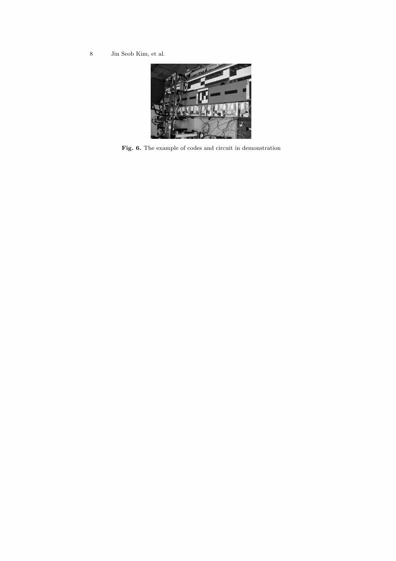
8 Jin Seob Kim, et al.
Fig. 6. The example of codes and circuit in demonstration
Toward Self-Replication of Robot Control Circuitry by Self-Inspection Jackrit Suthakorn Gregory S. Chirikjian* Dept. of Mechanical Engineering Dept. of Mechanical Engineering Mahidol University Johns Hopkins University Bangkok, THAILAND Baltimore, MD 21218, USA [email protected] [email protected] * corresponding author Extended Abstract
The concept of man-made self-replicating machines was first proposed by John von Neumann, more than fifty years ago [1], and this led to a flurry of related works [2,3]. However, there has never been a physical implementation of his universal constructor architecture in a robotic system. In contrast there have been a number of implementations of self-assembling mechanical systems [4,5]. Prior to our other recent work (see [6]), an autonomous self-replicating mechanical system had not been developed. In contrast to passive self-assembly, a self-replicating system actively utilizes an original unit to assemble a copy of itself from a collection of passive components. However, this does not require the use of von Neumann's universal constructor architecture. In the present work, we demonstrate a non-von-Neumann architecture for the replication of a transistor circuit by active self-inspection. That is, there are no instructions stored about how to construct the circuit, but information observed about the spatial organization of the original circuit is fed into the circuit itself to provide assembly commands. The circuit then drives a larger electromechanical (robotic) system in which it is embedded to cause the production of a replica of the original circuit. In the work presented here, only replication of the control circuit is of interest. In the current context, the electromechanical hardware is viewed as a tool which is manipulated by the control circuit for its own reproduction (much in the same way that deer living in a forest can reproduce without an associated reproduction of the forest itself). This architectural paradigm is demonstrated with prototypes that are reviewed here and compared with an implementation of the universal constructor concept.
This work complements our recent work in which we have demonstrated various aspects of robotic self-replication with a series of prototypes including: (1) remote-controlled systems capable of assembling copies of an original robot from subsystems [7]; (2) a semi-autonomous system in which a remote-controlled robot builds fixtures which then autonomously assist in assembling a copy of the original robot [8]; (3) an autonomous self-replicating mechanical system (in which the computer program for the replica is pre-installed) which functions without human intervention [6]. The present work differs substantially from those works because it focuses on the replication of the ``brains’’ of simple robotic systems from individual transistors rather than treating the microprocessor as a preconstructed subsystem in the assembly process.
Over the years the concept of self-replicating robotic systems has been considered to be useful in
many applications, especially, space applications. Many researchers have discussed the possibilities of using such a system in space and planetary exploration [9,10,11]. In order to make this vision realistic, one must show that self-replication of intelligence (SRI) is possible. We believe that the non-von-Neumann concept of self-replication by self-inspection, first addressed theoretically by Burks [13], Arbib [12], and Liang [ 14] (and implemented in electromechanical systems for the first time here) is a paradigm which is very robust and worthy of consideration.
The SRI concept: Ideally, for a robotic system to be truly self-replicating, it would have to
demonstrate the ability to assemble all of its own subsystems from the most fundamental components. In the case of the robot controller, we consider the most fundamental components to be transistors, resistors, capacitors, etc., whereas microcontrollers are too complex to be considered as basic elements.

Our approach is to build a circuit capable of controlling an electro-mechanical system to re-build replicas of the control circuit from the most fundamental electronic components. In the von Neumann universal constructor paradigm, an associated instruction code is also required. In contrast it is possible to replicate a particular system by self-inspection without invoking von Neumann's universal constructor. We illustrate both concepts in hardware designed and constructed by students in a Mechatronics course taught at Johns Hopkins University in 2003. Two prototypes illustrate replication by self-inspection, and one demonstrates the universal constructor. In all three cases, pre-built electro-mechanical systems (called the SRI-builders) use the transistorized circuit as its controller. While in the von Neumann paradigm, the controller follows instructions that are explicitly encoded (and hence must reproduce the code for the overall system to be self-replicating), in the self-inspection paradigm, actions are taken implicitly as a result of observing the spatial layout of components in the original and feeding that information into the circuit itself. Clever electromechanical design ensures that observations obtained during self-inspection are translated directly into actions without requiring the interpretive step of consulting a long sequence of encoded construction commands. (1) A von Neumann Universal Constructor Prototype: The robotic system is a two-degree of freedom gantry-style robot, consisting of two arms separated by a constant offset. One degree of freedom is the position along the entire system that includes the feeders and the assembly boards. The other is the vertical direction, perpendicular to the system foundation, used by the arm to pick up and drop off code and circuit pieces. The position and arm commands received by the control circuit are carried out and controlled by switches designed and placed to be operated at the completion of each movement. There are two boards being assembled at any given time, one for the circuit and one for the code. The circuit board is pre-wired so that when the circuit blocks are dropped into place, all of the chip connections are, in theory, instantly made. Each line of code consists of three bits fed simultaneously to a reader array consisting of three optical sensors that detect the value of the bits below – black being zero, white being one. These photo sensor cells are coupled with infrared LED emitters that provide IR light to be sensed by the sensors; ambient visible light has the potential of providing sufficient light energy to reflect off the code and be detected by the sensors, but the IR emitters guarantee the readability of the code. See Figure 1.
Figure 1: Side View of the Replicating system
(2) Non-universal self-replication by self-inspection (design 1): This self-replicating control circuit has the ability to identify the proper electronic components required, translate information about its own constituent parts obtained from self-inspection into mechanical tasks that create a replica , and transfer all functions to the replica. There is no list of instructions in the form of a code. Each electronic component has a black-and-white color code. Parts are loaded into feeders, and as a reading head traverses the control circuit, the information about which part of the control circuit is being observed is fed into the circuit itself. This actuates the solenoid in the appropriate feeder to release the parts needed to form the replica. Parts then slide

down an incline and form an orderly array. The reading head continues to move and creates replicas until resources are completely utilized or its track ends. The design is scalable and the components are modular, allowing many different levels of intelligence to be replicated. This concept is one of many which we are investigating to enable self-replicating robots to perform complex behaviors. See Figure 2.
Figure 2: Side View of the Replicating system
(3) Non-universal self-replication by self-inspection (design 2): This robotic system is an X-Y table constructed from modified LEGO components. A photo-transistor sensor system is attached to the end-effector of the X-Y system in order to inspect the control circuit (the components of which are each assigned a unique black and white code). On the top of the X-Y system, a set of component feeders is installed. The circuit converts the signal from the sensor system to control the component feeders to release the correct component to the parts assembler. The parts assembler then arranges all the components to create a new replica of the control circuit. See Figure 3.
Figure 3: Side View of the Replicating system

Discussion Whereas von Neumann's architecture for self-replicating kinematic automata is the most widely known approach, it is not the only one. Self-reproduction by self-inspection in which a non-universal constructor `reads' an original device and `writes' a copy by executing a very small set of hardwired commands is an alternative. In our experience observing students attempting to build self-replicating devices, self-replication by self-inspection appears to be a more robust and less complicated alternative to the universal constructor. Acknowledgements The hardware described here was developed by the students in a Mechatronics course offered in the Department of Mechanical Engineering at The Johns Hopkins University. This work was funded by the department and a phase I NASA/NIAC award. The hard work and creative efforts of the following students are gratefully acknowledged: Group 1: Jin Seob Kim, Art Rivera, Danielle Soya, Danny Dokko, Landon Unninayar, Mohammed Ramadon, Robynn Denzene, Zain Syed; Group 2: Whitney A. Hastings, Mike Labarre, Anand Viswanathan, Stephen Lee, David Sparks, Tony Tran, Jason Nolin, Rob Curry, Michael David, Stanley Huang; Group 3: Keenan Wyrobek, Jesse Theiss, Jeff McDonald, Ezel Baltali, Eric Dorflinger, Austin Moyer, Michael Comeau, Ryan Lavender, CJ Pawlowski, Patrick Danaher REFERENCES [1] von Neumann, J., ``The General and Logical Theory of Automata,'' in Cerebral Mechanisms in Behavior, Proc. Hixon Symp., L.A. Jeffress, ed., pp. 1-31, Wiley, New York, 1951. [2] Kemeny, J.G., ``Man viewed as a machine,'' Scientific American, 192, pp. 58-67, 1955. [3] Moore, EF, ``Artificial Living Plants,'' Scientific American, 195, pp. 118-126, 1956. [4] Jacobson, H., ``On Models of Reproduction,'' American Scientist, 46, pp. 255-281, 1958. [5] Penrose, L.S., ``Mechanics of Self-Reproduction,'' Annals of Human Genetics, 23, pp. 59-72, 1958. [6] Suthakorn, J., Cushing, A.B., and Chirikjian, G.S., “An Autonomous Self-Replicating Robotic System,
Proceedings of the 2003 ASME/IEEE International Conference on Advanced Intelligent Mechatronic (AIM), Kobe, Japan, 2003.
[7] Chirikjian, G.S., Suthakorn, J., “Toward Self-Replicating Robots,” Proceedings of the 8th International Symposium on Experimental Robotics (ISER) 2002, Italy, 2002.
[8] Suthakorn, J., Kwon, Y.T., and Chirikjian, G.S., “A Semi-Autonomous Replication System,” Proceedings of the 2003 IEEE International Symposium on Computational Intelligent in Robotics and Automation (CIRA), Kobe, Japan, 2003.
[9] Freitas, R.A., Jr., “Report on the NASA/ASEE Summer Study on Advanced Automation for Space Missions”, J. British Interplanetary Society, Vol. 34, 1980, pp 139-142.
[10] Chirikjian, G.S., Zhou, Y., Suthakorn, J., “Self Replicating Robots for Lunar Development,” IEEE/ASME Transactions on Mechatronics, Special Issue on Self-Reconfigurable Robots, Vol. 7: Issue 4, 2002.
[11] Suthakorn, J., Zhou, Y., and Chirikjian, G.S., “Self-Replicating Robots for Space Resource Utilization,” Proceedings of the 2002 RoboSphere: Self-Sustaining Systems, NASA Ames Research Center, California, 2002.
[12] Burks, A.W., ``Computation, behavior and structure in fixed and growing automata,'' Behavioral Science, 6, 5-22, 1961.
[13] Arbib, M.A., ``Simple Self-Reproducing Universal Automata,'' Information and Control, 9, 177-189, 1966. [14] Laing, R.A., ``Automaton Models of Reproduction by Self-Inspection,'' Journal of Theoretical Biology, 66, pp. 437-456, 1977.