Embed Size (px)
Citation preview

HAL Id: hal-01154703https://hal.archives-ouvertes.fr/hal-01154703
Preprint submitted on 27 May 2015
HAL is a multi-disciplinary open accessarchive for the deposit and dissemination of sci-entific research documents, whether they are pub-lished or not. The documents may come fromteaching and research institutions in France orabroad, or from public or private research centers.
L’archive ouverte pluridisciplinaire HAL, estdestinée au dépôt et à la diffusion de documentsscientifiques de niveau recherche, publiés ou non,émanant des établissements d’enseignement et derecherche français ou étrangers, des laboratoirespublics ou privés.
An approach for predicting the internal behaviour ofball bearings under high moment load
Christophe Bovet, Laurent Zamponi
To cite this version:Christophe Bovet, Laurent Zamponi. An approach for predicting the internal behaviour of ball bear-ings under high moment load. 2015. hal-01154703
An approach for predicting the internal behaviour ofball bearings under high moment load
Christophe Boveta,b,∗, Laurent Zamponib
aAix-Marseille Universite, CNRS, ISM UMR 7287, 13288, Marseille cedex 09, FrancebAirbus Helicopters, Aeroport International Marseille Provence, 13725 Marignane, France
Abstract
This paper presents a modelling approach for predicting the internal dynamicbehaviour of ball bearings under high moment loads. This type of loading is aspecific feature of helicopter main gear boxes because of special design rules andthe high structural flexibility of such systems. The ball bearing model proposedhere is not limited to planar systems and incorporates several different phenom-ena such as contact deformation, elastohydrodynamic contact, internal clearanceand cage run-out. The cage–race interaction is treated as a hybrid short jour-nal model, which ensures continuity of the contact force at the transition fromthe hydrodynamic to metal-to-metal regime. In the dynamic analysis of sucha severely loaded bearing, the dependence of the shaft-to-inner-ring force oninner race position cannot be neglected. An equivalent viscoelastic hinge jointhas been developed, it produces an additional force that represents the overallrigidity of the system. The stiffness parameters of the joint are identified us-ing global finite element simulations. A ball bearing loaded with two differentmoments is chosen as an example. Relevant results concerning the internal dy-namic behaviour are given. The predicted cage trajectory has been comparedto experimental observations, and good agreement has been found.
Keywords: Multibody dynamics, Bearing dynamics, Contact Analysis, CageAnalysis, Realistic Joint
1. Introduction
In the aircraft industry, and in particular the manufacture of helicopters, thequest for maximum performance requires the power weight ratio to be maxi-mized. A power transmission gearbox of 300 kg can transmit several megawattsfrom the engines to the rotor (see Fig.1). Weight saving is essentially achieved5
by reducing the number of parts and their thicknesses. Such a strategy leads to
∗Corresponding author. Tel.:+3342939096Email addresses: [email protected] (Christophe Bovet),
[email protected] (Christophe Bovet), [email protected] (LaurentZamponi)
Preprint submitted to Mechanism and Machine Theory July 23, 2014
ManuscriptClick here to view linked References

increasingly flexible housings and shafts. Associated with the high power trans-mitted, this increasing flexibility causes relatively large strains in the powertransmission gearbox. Rolling bearings are naturally affected by housing defor-mation since any misalignment of rolling bearing races may cause damage to10
rolling element bearings and premature failure [1]. This structural deformationleads to an additional moment load on the rolling bearings. Also, the ball sep-arator or cage becomes a critical component. Previously there simply to ensurea uniform distribution of the rolling elements, it now experiences significantstresses, and cage fracture due to material fatigue frequently occurs. In power15
transmission gearboxes, rotating shafts are usually supported by three rollingbearings; two roller bearings support radial loads whereas the ball bearing mayexperience mainly thrust loads. This load distribution is obtained on accountof a large clearance between the outer race of the ball bearing and its housing.As each rolling bearing must experience an appropriate load, improved system20
reliability is expected. Thus, the load experienced by ball bearings comprises athrust load and an additional moment load inherent in structural deformation.This type of loading appears highly specific to the helicopter industry and islargely ignored in the literature. Indeed, the majority of rolling bearing dynamicanalyses published in the literature only consider axial or radial loads.25
Because of their critical role, rolling element bearings have been widely inves-tigated. Initial studies focused on static and quasi-static analyses. Stribeck wasamong the first to investigate the load distribution in rolling elements. Later,Lundberg and Palmgren studied the fatigue behaviour of bearings. Perhaps thefirst computer code to carry out static analyses of rolling bearings is credited30
to Jones [2]. This code was able to predict the load distribution, stiffness andfatigue life of rolling bearings. The work of Harris is also of great importance,with an excellent review of the work to be found in [3]. To address the problemof kinematic indeterminacy in quasi-static analyses, Jones [2] proposed the verycommonly used race control hypothesis. The hypothesis states that the spin35
velocity of contacts between rolling elements and race is zero on the race thatprovides the larger friction torque. The hypothesis determines the angular ve-locity of the rolling elements. Quasi-static analyses are very useful in the designof rolling bearings since they provide a fairly realistic load distribution for therolling elements, equivalent stiffness and predictions of fatigue life. However, it40
suffers from several limitations. Indeed, any treatment of cage behaviour, skid-ding or skewing phenomena, and time varying loads are outside the realm ofthe model. These limitations drove the development of dynamic rolling bearingmodels.
Walters [4] initiated this approach, proposing a dynamic model which in-45
tegrated the equation of motion of the cage in angular contact ball bearing.Kannel and Bupara submitted a simplified approach that makes use of therace control hypothesis [5] later contested by Meeks [6]. A major advance inthe understanding of the dynamic behaviour of rolling bearings was made byGupta with the well-known computer code ADORE [7]. The author developed50
a generalized dynamic formulation for various types of rolling bearings. The ge-ometrical generalizations allowed geometrical imperfections to be modelled and
2
manufacturing tolerances to be optimized [8]. The race control hypothesis wasreplaced by the dynamic equilibrium of each rolling bearing component. How-ever, ADORE seems unable to simulate ball bearings under high moment loads.55
In any event, no ball bearing dynamic analysis considering high moment loadshas been published in the literature. The absence of radial loading coupled tothe fact that the loaded race is floating leads to an unexpected behaviour of theinner race. This unexpected behaviour may be inherent in the too restrictedscope of the Gupta’s approach which neglects the link between the shaft and60
the inner race.In the realm of vibration analysis, several models have been proposed to
investigate the non-linear dynamic behaviour of a rotor-bearing system. Thesemodels often simplify physical phenomena such as lubricant traction or cage raceinteraction. The aim of these studies is to underline the influence of specific65
defects on the vibrational response. Non-linearities due to internal localizeddefects [9] or internal clearances [10] were investigated. Harsha and Natarajproposed an analytical model to show the effect of the run-out of the cage[11, 12]. Due to run-out of the cage, the rolling elements no longer remain equallyspaced. Surface waviness [13, 14], ring flexibility [15, 16], and fluctuations in70
rotational speed [17] were also studied.Dynamic modelling of multibody systems allows analysis, design, optimiza-
tion and control of complex mechanical systems[18] [19]. Joints were modelledin the past as idealized or simplified but the use of more realistic joints is ofgrowing interest with models of real cylindrical or spherical joint being devel-75
oped [20–24]. Recently, a model of a planar deep groove ball bearing that canbe used in planar multibody systems has been proposed [25]. This model modelwas used to estimate dynamic loads in a deep groove ball bearing [26, 27] andextended to include waviness defects [28]. Though several physical simplifica-tions were made, the multibody dynamic formalism appears to be well suited to80
the simulation of rolling bearings. Another interesting aspect of this approachis that the developed model can easily be included in a global dynamic study.Stacke et al. were the first to developed the bearing simulation tool beast basedon a multibody dynamic formalism [29]. The beast computer code allows thedynamic internal behaviour of rolling bearings to be analysed with a detailed85
treatment of contacts [30].This paper is concerned with the dynamic modelling of a ball bearing under
high moment loads. The approach presented here draws on multibody dynamicformalism but also proposes a detailed treatment of internal interactions forrolling contact or cage behaviour. This approach has already been used in a90
previous work to predict ball bearing behaviour in the event of failure of thelubrication system [31]. The proposed model is not limited to planar systemsand it includes several phenomena such as internal clearance and cage run-out. The contact force and moment calculations of rolling contacts are basedon the theory elastohydrodynamic lubrication [32, 33]. Lubricant traction is95
approximated assuming isothermal conditions [34]. The equivalent load to whichthe ball bearing is subject is highly specific to helicopter main gearboxes asthese experience only axial loads and moment loads. In such cases, standard
3

local approaches are unable to reproduce experimental observations becauseof the unexpected behaviour of the free race. Thus, the influence of the rest100
of the system can no longer be neglected. An equivalent viscoelastic hingejoint has been developed incorporating the overall stiffness of the helicoptermain gearbox. Rigidity and damping parameters of the joint are identifiedvia global finite element simulations. Moreover, the bearing excitation is sosevere that metal-to-metal contact occurs between the cage and the cage guiding105
race. To simulate this phenomenon and ensure continuity of the correspondingcontact law, a hybrid short journal model has been developed. This considersthe transition between the pure hydrodynamic and dry contact regimes. Floreset al. [20, 22] presented a similar approach for simulating journal bearings.
The paper is organized in the following manner. Section 2 presents the110
overall modelling approach and the equations of motion of a constrained multi-body dynamic system are briefly reviewed in Section 3. Section 4 describes theinternal ball bearing interactions. Finally, two numerical examples and rele-vant results are given in section 5. Results are discussed and compared withexperimental observations.115
Figure 1: Helicopter main gearbox
2. Modelling strategy of the system
This section presents the strategy adopted for managing the dynamic analy-sis of rolling bearings of helicopter power transmission gearboxes. The dynamicanalysis aims to predict cage instabilities and localized non-linear phenomenaas ball skidding or impacts. Simplified models like such as those proposed in the120
realm of vibration analysis are not satisfactory. Such assumptions as race controlor the regular distribution of rolling elements are excluded. Direct integrationof the equations of motion of the complete gearbox, including the structuralflexibility, gears and rolling bearings, represents a prohibitive cost in terms ofcpu time and memory. Hence an alternative strategy with a restricted scope125
4
has been developed. The dynamic analysis is restricted to one rolling bearingat a time.
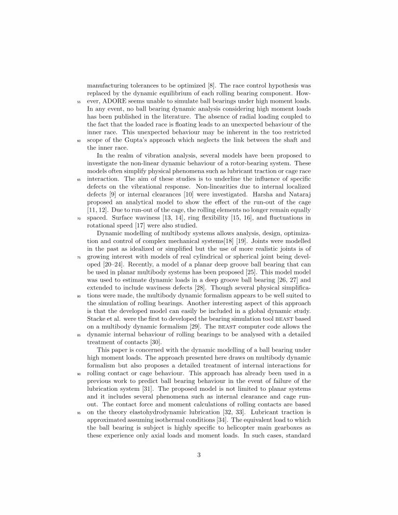
In the approach proposed by Gupta, the load is applied to the inner racewhich is free to move to balance the prescribed load and rolling element contacts.The outer race is rigidly connected to the housing. The main necessary item of130
data is the equivalent load seen by the rolling bearing. Assuming rigid shaftsand housings, a simple static equilibrium provides an estimate of this equivalentload[3]. However, this method is not suitable for aircraft gearboxes since itneglects the structural flexibility of the mechanism and it grossly underestimatesthe value of the equivalent load.
Global static finite elementanalysis
Local dynamic analysis ofrolling bearings
Analysis of internaldynamic behaviour of
rolling bearings
Perturbation of globalanalysis
Identification of equivalenthinge joint parameters
Equivalent loads onrolling bearings
Evolution of internalbehaviour over time
Viscoelastic hingejoint
static frame
Applied load
on inner race
Figure 2: Modelling approach
135
In the proposed approach, a better estimate of the equivalent load is obtainedvia a global finite element analysis. Thus, a static analysis incorporating thecomplete system with gears and rolling bearings is carried out. Several optionsare available to model rolling bearings, their stiffness and geometrical defects[1, 35]. In this paper, finite elements are also used to model the static behaviour140
of rolling bearings. Some interesting data on rolling bearings merge from thestatic analysis such as the load or pressure distribution on rolling elements, andrace deformation. In this study, races are assumed to be rigid for the dynamicsimulation. These data are used to reconstruct the equivalent load as seen bythe rolling bearing.145
Although the global finite element analysis undeniably provides a betterassessment of the equivalent load, it appears from the author’s experiments that,
5
in its current form, the model is unable to reproduce the dynamic behaviourof a ball bearing subject only to axial and moment loads. In particular, thehighly perturbed behaviour of the inner race seems to be linked to the high150
value of the moment. This unusual behaviour is accentuated by the absence ofany radial load. Also, it must be noted that allowing the inner race to movefreely in the dynamic analysis is equivalent to neglecting the link between theinner race and the shaft. Indeed, if the equivalent load provided by the globalstatic analysis takes into account the rigidity of the complete system, this load is155
only exact at the point of static equilibrium. During the dynamic analysis, theposition and the orientation of the inner race are slightly shifted from the staticconfiguration. The value of the load imposed by the shaft on the inner race isthen naturally modified. Thus the equivalent load prescribed for the inner racemust be dependent on the configuration of the inner race during the dynamic160
analysis. This dependence must represent inertia, damping and rigidity of therest of the system.
In this work, an additional viscoelastic hinge joint is proposed to modelthis dependence on the inner race configuration. The hinge joint constrains theactual configuration of the inner race within a frame that corresponds to the165
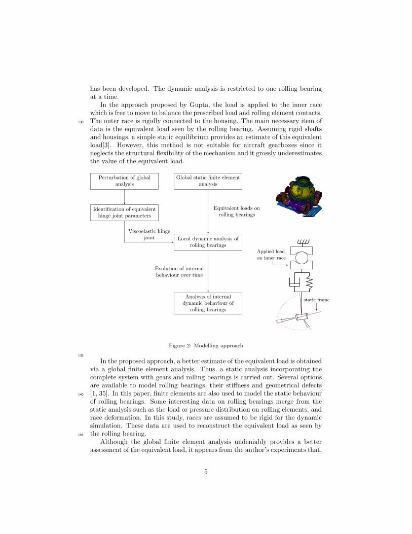
static one. Thus, an additional force that corresponds to the rigidity of the restof the system is considered when the position of the inner race shifts from thestatic solution. In the vicinity of static equilibrium, a linear viscoelastic hingejoint seems sufficient to model this additional force. The multibody dynamicformulation of the hinge joint is described in more detail in Section 3.2. Virtual170
work takes the form (2), where u and ψ represent the shift in position andorientation respectively.
δWhinge = −δuTHuu− δψTHψψ − δuTGuu− δψTGψψ (1)
Rigidity parametersHu andHψ are identified using a minimization process.In the global finite element static analysis, an average mean displacement ele-175
ment is added between the inner race and its centre. Relative displacements dueto various perturbation forces and moments applied to this centre of the innerring are then computed. Minimization of the difference in behaviour betweenthe finite element model and the equivalent hinge joint furnishes the rigidityparameters Hu and Hψ (2). Unfortunately, damping parameters Gu and Gψ180
cannot be evaluated by such a process. In this work, damping parameters areassumed to be proportional to their corresponding rigidity parameter. A coef-ficient of 10−6 seems to provide good results.
minHu,Hψ
∑
i≤npert
∥∥uiFE − uieq(Hu,Hψ)∥∥2 +
∥∥ψiFE −ψieq(Hu,Hψ)∥∥2 (2)
6

3. Description of multibody dynamic formalism185
3.1. General description
Various theories are available in multibody dynamic analysis such as theformalisms of the floating frame of reference, absolute nodal coordinates [18] orthe finite element approach [19]. This work uses the finite element approach.The configuration of a rigid body is uniquely defined by the translation of an190
arbitrary point and the rotation operator mapping the initial to the currentconfiguration. Thus, it can be expressed as a time-dependent application:
C =
(x,R) : R+ 7→ R3 × SO(3)
(3)
For rigid bodies, it is easier to use a rotation parameterization rather thanworking directly with the special orthogonal group SO(3). Such a choice ofparameters is a crucial point since they must be able to describe rotations of195
large amplitude [36]. Most approaches consist of expressing an arbitrary rota-tion in terms of elementary rotations about well defined axes such as Euler orBryant angles. Such a geometric description provides an intuitive descriptionof rotational motion but has the drawback that it exhibit singularity. Eulerparameters are also commonly used. This method is free of any singularity but200
it needs one redundant variable. Their use requires an additional non-linearnormality constraint to be imposed. The present work employs the ConformalRotation Vector. This parameterization seems a good choice for representinglarge rotations computationally. Only three independent parameters are needed.Also, it has no singularity over one full rotation and has a very linear behaviour205
in terms of rotation angles[37]. A correction procedure for the Conformal Ro-tation Vector is needed to allow rotation of any magnitude. Thus, each bodyrequires the use of six parameters. The generalized coordinates of all bodies arecollected in a column vector q.
Joints interconnect the bodies in a multibody system. In the ideal case,these connections are expressed as algebraic equations. Kinematic constraintsare distinguished into holonomic and non-holonomic constraints. Holonomicconstraints Φ are formulated as implicit functions of the generalized coordinatesand time (4). Non-holonomic constraints Φnh encountered in this work arealways linear in velocities and can be expressed in the form (5) where q notationdenotes the time derivative of q.
Φ(q, t) = 0 (4)
Φnh(q, q, t) = Bnh(q)q + gnh(t) (5)
Non-holonomic constraints are considered using a dissipation function D, withp a penalty coefficient and k is scaling factor. λ is a set of Lagrange multipliers.The superscript T is the transpose operator.
D =p
2ΦTnhΦnh + kλTΦnh (6)
7

Thus, the constrained dynamic problem is treated by augmenting the functionalin Hamilton’s principle. In (7), L is the Lagrangian of the system and δW is thevirtual work of external forces that takes into account non-conservative loads.
∫ t2
t1
[δ(L − p
2ΦTΦ− kλTΦ−D
)+ δW
]dt (7)
By performing the variational calculation and integrating by parts over time, theequations of motions of a constrained system are then obtained. M , B are re-spectively the mass matrix and the matrix of gradients of holonomic constraints.The force vector g is the sum of the external, internal and complementary inertiaforces. r is the dynamic residual vector.r(q, q, q,λ, λ) = Mq +BT (pΦ + kλ) +BT
nh(pΦnh + kλ)− g (q, q, t) = 0Φnh(q, q, t) = 0
Φ(q, t) = 0(8)
This non-linear second order differential-algebraic system (8) is solved using210
the hht scheme [38]. Derived from the Newmark method, this allows a directsolution of a second order differential system. This scheme is unconditionallystable and second order accurate even in the presence of numerical dissipation. Italso generates less numerical dissipation than the damped Newmark algorithm.The use of these unconditionally stable schemes is of particular importance in215
contact problems involving friction and rolling where the dynamic response isvery complex due to the large, rapidly varying contact and frictional forcesapplied to the system [39].
To estimate the solution increment, the scheme requires the linearized formof the dynamic equilibrium. Knowing an approximate solution (q?, q?, q?,λ?, λ?)at time t and considering a correction of the solution (∆q,∆q,∆q,∆λ,∆λ), dif-ferentiation of (8) provides :[M 00 0
] [∆q
∆λ
]+
[Ct kBT
nh
kBnh 0
] [∆q
∆λ
]+
[Kt kBT
kB 0
] [∆q∆λ
]=
[−r?−Φ?
]+O(∆2)
(9)where Kt and Ct are the tangent stiffness and the tangent damping matrices.
Kt =∂r
∂qand Ct =
∂r
∂q(10)
Finally, the non-linear equation of motion is solved iteratively by Newton’smethod. The exact form of the tangent operator is necessary to obtain quadratic220
convergence of Newton’s method. However, such exactness is often too costlyto obtain simply for the purposes of iteration convergence. From the author’sexperience, an approximate form of the tangent operators often leads to lessCPU time. The computational procedure is summed up in Fig.3
3.2. Description of a viscoelastic hinge joint225
In the rolling bearing model which has been developed, the kinematics ofboth races are constrained. The outer race is constrained via an ideal hinge joint
8

Time incrementation
t = t + h
Initial prediction
q0, q0, q0
Evaluation of residues
r(q, q, q),Φ(q, q)
Check for convergence
‖r‖ ≤ ηdyn, ‖Φ‖ ≤ ηφ
Evaluation of correction
∆q,∆λ
Incrementation of solution
q = q + ∆q,λ = λ + ∆λ
no
yes
Evaluation of matrices
M ,B
Evaluation of interactions
g(q, q)
Computation oftangent operator
Kt,Ct
Figure 3: Iteration procedure of the implicit time integration algorithm
within an reference frame. To account for the overall stiffness of the helicoptermain gearbox, the inner race is constrained via a viscoelastic hinge joint. Inthis section, the formulation of the viscoelastic hinge joint is derived from the230
ideal one.Let (ξ1, ξ2, ξ3) and (µ1,µ2,µ3) be two orthonormal triads attached to
nodes A and B, respectively, at the reference configuration (see Fig.4(a)). Let(ξ1, ξ2, ξ3) and (µ1, µ2, µ3) be the triads obtained by mapping the referenceone into the actual configuration. The corresponding rotation operators areRA and RB (11). Since both races are constrained within a fixed frame, theconfiguration of the frame (A, ξ1, ξ2, ξ3) is assumed constant. Thus, variationsand time variations of xA and RA are nil.
µi = RAµi ; ξi = RBξi (11)
The ideal hinge joint is modelled by introducing five constraints [19]; threeimposing the equality of node position
xA = xB (12)
and two enforcing coaxiality of µ3 and ξ3.
µT1 ξ3 = 0 ; µT2 ξ3 = 0 (13)
These five constraints are usually collected in a constraint vector Φ. The con-straint gradient B is then obtained by differentiating the constraint vector such
9

z
x
y A, B
ξ3, µ3
ξ2
ξ1µ1
µ2
ϕ
ϕ
(a) Local frames to the hinge joint
z
x
y A,B
ξ3
ξ2
ξ1
µ1
µ2
µ3
ψ1
ψ2
(b) Deformation kinematics of flexible hinge(xA ≡ xB)
Figure 4: Geometrical description of the hinge joint
that (see [19] for detailed calculations):
δΦ = Bδq (14)
Flexible joints are not dealt with Lagrange multipliers; the elastic behaviourof the joint is associated with a strain energy Vc and the viscous behaviouris associated with non-conservative virtual work δWnc. Both are functions ofextensional and shear strain u and bending strain ψ (15); small strains areassumed (see Fig.4(b)). The rotation operator in u replaces strains in thenatural frame of the hinge. The superscript in u denotes for a skew symmetriclinear transformation of u equivalent to the cross product.
u = RTA(xB − xA) and ψ =
ψ1
ψ2
=
−µT2 ξ3µT1 ξ3
(15)
u = RTAxB and ψ =
(˜µ2ξ3)TRBΩB
−(˜µ1ξ3)TRBΩB
(16)
For the strain energy, the simplest choice may be a quadratic form, its variationbeing given by (17), where Hu and Hψ are matrices of elastic coefficients inextension, shear and bending. In (18), Gu and Gψ are matrices of viscouscoefficients in extension, shear and bending. All matrices representing bendingcoefficients are assumed to be diagonal.
δVc = −δWc = δuTHuu+ δψTHψψ (17)
δWnc = −δuTGuu− δψTGψψ (18)
10

Finally, the contribution of the viscoelastic joint in the force vector g in (8) arederived. In the expression for generalized forces, TB and ΩB are respectively thetangent operator of rotation and the material angular velocity of the rotationRB . The iteration procedure of the implicit time integration algorithm requiresthe increment of generalized forces ∆gc and ∆gnc. From (19-20), a rather goodestimate of tangent operators can be obtained.
gc = −
RAHuRTA(xB − xA)
T TBRTB
((˜µ2ξ3)Hψ,1ψ1 − (˜µ1ξ3)Hψ,2ψ2
)
(19)
gnc = −
RAGuRTAxB
T TBRTB
((˜µ2ξ3)Gψ,1(˜µ2ξ3)T + (˜µ1ξ3)Gψ,2(˜µ1ξ3)T
)RBΩB
(20)
4. Internal modelling of non-planar ball bearings
Internal interactions are classified into two main parts, namely interactioninvolving rolling elements and interaction between cage and race. These inter-235
actions are treated with compliant contact models. With such models, contactforces are expressed as continuous functions of contact parameters and contactgeometry. These contact parameters are computed from the positions and ve-locities of the contacting bodies. Fig.5 shows the internal modelling of theball bearing. The geometric model of the ball bearing is shown in Fig.6. All240
geometric calculations involved are done analytically. The interaction modelprovides contact forces and moments.
Inner raceApplied Load, ωir prescribedViscoelastic hinge joint with staticframe
Rolling elementrace interactionPonctual contactHertz & EHD model
Outer raceωor prescribed
Hinge joint with reference frame
Cage race interactionConformal contact
Hybrid short journal model
Rolling elementcage interactionPonctual contact
Hertz & EHD model
Figure 5: Ball bearing model description
4.1. Interaction involving rolling elements
Interaction involving rolling elements consists of interaction between ballsand races and interaction between balls and cage pockets. The treatment of245
these rolling contacts is of primary importance since they greatly influence thedynamic behaviour of the ball bearing.
11

di2
Di2
riCi
Oi
hi2
B
do2
Do2
roCo
Oo
ho2
B
D dp wc
dc2
2πZ
Oc
ec
Figure 6: Geometry and dimensions of the ball bearing components
Geometric calculations. From a geometrical point of view, the former is equiv-alent to the geometric interaction between a torus and a sphere. The latteris characterized by the geometric interaction between a cylinder and a sphere.This simple and well known interaction is not reviewed here, and only the in-teraction between a torus and a sphere will be considered. Fig.7 shows thecontact configuration. Let (Oi,X
0i ,Y
0i ,Z
0i ) be an orthonormal triad attached
to the inner race such that Z0i is coincident with the inner race axis. Let the
coordinates of the ball centre Ok in this triad be (Xk, Yk, Zk). The potentialcontact between the torus and the sphere is necessarily contained in the planethat passes through Ok and includes the line (Oi,Z
0i ). Let us define a new
frame (Oi,Xi,Yi,Zi) rotated about Z0i such that (Oi,Xi,Zi) is the plane
that contains the potential contact. The magnitude of the rotation is
γ = arctan
(Yk
Xk
)(21)
Considering the triangle drawn in Fig.7, the contact angle α and the contactdeflection δ can be easily obtained (22) (23). A negative δ indicates no contactbetween the ball and the race. The contact between the outer race and therolling elements can be expressed in a very similar form. Knowing the locationof the contact point and the contact deflection, all the geometric and kinematicdata required by the contact model are available.
tanα =Zk
di2−√X2k + Y 2
k
(22)
δ =
√Z2k +
(di2−√X2k + Y 2
k
)2
+D
2− ri (23)
12

di2
ri
Ci
Ok
Oi
Xi
Zi
√X2k+ Y 2
k
Zk
α
δ
Figure 7: Geometrical interaction between the inner race and a ball
Rolling contact model. The contact force and moment calculations of rollingcontacts are based on the elastohydrodynamic theory of lubrication. In thiswork coupling between normal and tangential contact problems is neglected.The normal load is computed first. Since an elastohydrodynamic pressure profileis similar to the hertzian profile, it is reasonable to use the classical hertzianpoint contact solution. Thus, the normal load Fn is linked with the contactdeflection δ by (24). kh is the contact rigidity which depends on the curvatureof the contacting surfaces and the material properties of contacting bodies. Moreinformation about Hertz contact theory can be found in [40].
Fn = kh δ3/2 (24)
The fluid film thickness and lubricant traction are computed. The fluidfilm thickness may be estimated using the explicit formula proposed by Ni-250
jenbanning et al. [32, 33]. Lubricant traction is computed using the work ofJacod [34]. The elastohydrodynamic lubrication contacts are assumed smooth.If isothermal conditions are assumed, an explicit formula is available for thelubricant coefficient of friction. Otherwise, the estimate of lubricant tractionrequires the solution of a non-linear equation to compute the temperature in-255
crease of the fluid film. A wlf model [41] describes the lubricant rheology. Thenon-Newtonian behaviour of the lubricant is modelled using the Eyring model.The fluid used in this study corresponds to the nato o-156 specification. Fig.8
13

compares the friction coefficient of several models. Under isothermal conditions,the friction coefficient is slightly overestimated. In the legend of Fig.8, the ad-260
jective approximate refers to the way which the pressure-viscosity coefficient iscalculated[41]. Considering the huge number of simulated contacts and the rel-atively small discrepancies between the different models, isothermal conditionsand approximate value of the pressure-viscosity coefficient are used.
0 5 10 15 20Slip to roll ratio (%)
0.0
0.5
1.0
1.5
Fri
ctio
nco
effic
ient
(%)
Friction coefficient of NATO O-156 at 60C
Approx. WLF IsothermalWLF IsothermalApprox. WLFWLF
Figure 8: Typical friction coefficient, comparison between various models.
4.2. Interaction between race and cage265
This paper is concerned with the modelling of ball bearings of helicoptermain gearboxes. In such bearings, the cage is centred on the outer race. Ifthe interaction between the cage and the race is mainly hydrodynamic, thendue to the high moment prescribed, metal-to-metal contact may occur. Thus,a transition model has been developed to ensure continuity of contact forces270
between the different regimes. This model is based on the work of Flores etal.[20, 22].
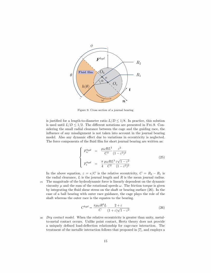
Hydrodynamic model. A commonly accepted approach is to employ the theoryof lubrication for journal-bearings Excellent reviews of the theoretical back-ground and basic principles are available in specialized books such as Pinkusand Sterlicht [42] or Frene et al.[43]. The pressure distribution of thin viscousfluid films is governed by the Reynolds Equation. Analytical solutions of thispartial differential equation can be obtained via several assumptions on fluidflow and boundary conditions. The hydrodynamics of the race cage contactis simulated by the well-known short journal bearing solution [42]. The shortjournal bearing solution is derived by neglecting circumferential variations in thefluid pressure and assuming Gumbel boundary conditions for the pressure. TheGumbel conditions, which account for the film breakdown, take into accountthe existence of a zero pressure zone. Even though it leads to a violation of thecontinuity of the fluid flow in the film, the Gumbel conditions furnish betterpredictions of the load capacity of the journal bearing. The short journal model
14
φ
θ
h(θ)
αe
Os
OhFluid film
ω n
t
F hyd
R1
R2
Figure 9: Cross section of a journal bearing
is justified for a length-to-diameter ratio L/D ≤ 1/8. In practice, this solutionis used until L/D ≤ 1/2. The different notations are presented in Fig.9. Con-sidering the small radial clearance between the cage and the guiding race, theinfluence of any misalignment is not taken into account in the journal bearingmodel. Also any dynamic effect due to variations in eccentricity is neglected.The force components of the fluid film for short journal bearing are written as:
Fhydn =µωRL3
C2
ε2
(1− ε2)2
Fhydt =π
4
µωRL3
C2
ε√
1− ε2(1− ε2)2
(25)
In the above equation, ε = e/C is the relative eccentricity, C = R2 − R1 isthe radial clearance, L is the journal length and R is the mean journal radius.The magnitude of the hydrodynamic force is linearly dependent on the dynamic275
viscosity µ and the sum of the rotational speeds ω. The friction torque is givenby integrating the fluid shear stress on the shaft or bearing surface (26). In thecase of a ball bearing with outer race guidance, the cage plays the role of theshaft whereas the outer race is the equates to the bearing.
Chyd =πµωR3L
C
2 + ε
(1 + ε)√
1− ε2(26)
Dry contact model. When the relative eccentricity is greater than unity, metal-280
to-metal contact occurs. Unlike point contact, Hertz theory does not providea uniquely defined load-deflection relationship for cage-race interaction. Thetreatment of the metallic interaction follows that proposed in [7], and employs a
15
Lundberg empirical load-deflection relationship to determine normal load. Froma prescribed contact deflection, the method proposed by Lundberg requires the285
solution of a non-linear equation to compute the contact load F dryn . A goodinitial guess was put forward by Palmgren (see [7] p.38-39). The tangential
force F dryt is then obtained assuming complete slip of the contact area.
Hybrid short journal model. Both interaction models for the hydrodynamicregime and metal-to-metal contact have been presented. Examining (25) and(26), it appears that when the fluid film thickness becomes very thin, i.e. thejournal is very close to the bearing surface, the force and torque due to thelubricant tend to infinity (27). As F dry is zero at the beginning of the contact,a simple transition between the hydrodynamic and the dry interaction modelwill inevitably create a discontinuity in the contact relationship. This disconti-nuity inadmissible and leads to absurd results in the dynamic analyses of ballbearings.
Fhydn ∼ε→1
µωRL3
C2
1
(1− ε2)2
Fhydt ∼ε→1
π
4
µωRL3
C2
1
(1− ε2)3/2
(27)
To avoid numerical instability and to ensure continuity of the contact rela-tionship, Flores et al. [20, 22] proposed the definition of a boundary layer. Inthis layer, the contact force is a weighted average of hydrodynamic and metal-lic forces. A physical interpretation of the boundary layer may be that layerin which the lubrication regime becomes mixed due to surface asperities. Thelayer is defined by a size e0, the corresponding relative size being defined byε0 = e0/C. The choice of e0 must made carefully. Too high a value may greatlyaffect the behaviour of the model, while discontinuities may reappear with toosmall a one. A typical value for ε0 is 5%. Examining (27), a linear weight-ing function seems insufficient to remove the discontinuity. The present modelmakes use of a different function weighting function fF .
fF (ε) = exp
(2χ(ε)
χ(ε)− 1
); χ(ε) =
ε− 1
ε0(28)
For the torque, the linear function fC . propose by Flores et al. is used.
fC(ε) =1 + ε0 − ε
ε0(29)
Finally, the approach is summarized in (30, 31). It should be noted that theclearance C used for the hydrodynamic force model is replaced by C+ e0 in thehybrid model. Fig.10 shows a typical form of the contact force of the hybrid
16

model.
F total =
F hyd if ε ≤ 1
fF (ε)F hyd + (1− fF (ε))F dry if 1 < ε ≤ 1 + ε0
F dry if ε > 1 + ε0
(30)
Ctotal =
Chyd if ε ≤ 1
fC(ε)Chyd + (1− fC(ε))Cdry if 1 < ε ≤ 1 + ε0
Cdry if ε > 1 + ε0
(31)
0.8 0.9 1.0 1.1Relative eccentricity
0
500
1000
1500
2000
2500
3000
Forc
e(N
)
hybrib model start
hybrib model end
Total forceWeighted hydrodynamic forceWeighted metal to metal force
(a) Force of the hybrid contact model
0.8 0.9 1.0 1.1Relative eccentricity
0
5
10
15
20
Mom
ent
(Nm
)
hybrib model start
hybrib model end
Total momentWeighted hydrodynamic momentWeighted metal to metal moment
(b) Moment on ball separator for the hybrid contactmodel
Figure 10: Hybrid conformal contact model data
17

4.3. Internal interaction in a multibody dynamic context
Models of internal interactions that occur in a ball bearing have been pre-290
sented. These models have to be replaced in the context of a multibody dynamicformalism. In particular, the implicit time integration procedure, which ensuresunconditional stability requires the computation of tangent operators Kt andCt (10). Thus, an estimate of the variation of contact forces must be provided.
Rolling contact. Regarding rolling contacts, the normal force depends only onthe generalized coordinates whereas FT depends also the derivatives of the gen-eralized coordinates. The normal load Fn is expressed in the form (32). Again,δ is the contact deflection. The contact rigidity kh depends on the curvatureof contacting surfaces and material properties. Finally, the contact force F isexpressed in the form (33) where n is the normal vector.
Fn(q) = kh(q) δ(q)3/2
(32)
F (q, q) = Fn(q) n(q) + FT (q, q) (33)
The contribution of the normal load in the tangent stiffness operator is com-puted from (34). In this expression, the influence variation in contact rigidityis neglected. Since geometrical interactions are computed analytically, explicitexpressions of δ and n are available, and an approximate explicit form of thiscontribution is thus obtained.
∆Fn(q) = ∆Fn(q) n(q) + Fn(q) ∆n(q)
' 32kh(q) δ(q)
12 ∆δ(q) n(q) + Fn(q) ∆n(q)
(34)
In the ehd lubrication model, the contribution of the tangential component is295
more cumbersome to derive. The approach presented in [31] is used again.
Conformal contact. The force and torque furnished by the hybrid short journalmodel depends on the generalized coordinates and their derivatives.
F total = F total(q, q) ; Ctotal = Ctotal(q, q) (35)
Their contribution to the tangent stiffness and tangent damping matricesare easily achieved once the variation of the contact deflection and the relativeeccentricity have been expressed. The differentiation of closed-form expression(25,26) gives the influence of the hydrodynamic force. For the dry contact, the300
finite difference of the Lundberg empirical formula gives a rather good estimate.It should be noted that the during the transition phase, the variation of theweight functions (fF , fC) has to be considered.
18

Dim. (mm) Outer race Inner raced 157.3 158.4r 9.906 9.753D 196. 130.h 166. 150.B 34. 34.
Rolling elementsD 19.05
Ball separatordc 158.dp 20.23ec 7.42wc 25.4Z 22
Table 1: Dimensions of the ball bearing
5. Results and discussion
The approach presented in this paper has been applied to the dynamic anal-305
ysis of a ball bearing whose dimensions are summarized in Tab.1. Balls andraces are made of steel, and the cage of bronze. As can be seen in Tab.1, thecage is guided by the outer race in this example.
Two different load cases have been considered, both having the specific fea-tures described previously. Thus, only thrust load and moment are present.310
The only difference between the load cases is the value of the moment. With amoderate value of moment load, load case (a) may be associated with a fairlygood behaviour of the ball bearing. The high value of moment load in the sec-ond load case will lead to rapid failure of the ball bearing. The second load casehas been experienced on a test rig, and experimental observations have been315
compared with the numerical results.The boundary conditions used are summarized in Tab.2. The outer race is
fixed rigidly within the housing. The rotation velocity of the inner race is 3060rev/min. As previously explained, the inner race is linked to the static referenceframe via a viscoelastic hinge joint. Rigidity and damping parameters of the320
joint have been identified using global finite element simulations (see Section 2).Perturbation forces and moments have been applied in the three directions toidentify the rigidity parameters of the joint. Their magnitudes lay in the ranges[−1000N ; 1000N ] and [−1000Nm; 1000Nm] respectively. Elastic coefficients inextension and shear are equal to 106N/mm, and bending coefficients are close325
to 105Nm/rad. The viscous coefficients matrices are assumed proportional tothe elastic coefficients matrices, and the scale factor is 10−6.
The internal modelling of the ball bearing is described in Section 4. The fluidused in this study corresponds to the nato o-156 specification. The operatingtemperature is assumed to be 100, this choice being based on experimental330
19

Prescribed load on inner raceLoad case case (a) case (b)Axial load 34000N 34000NRadial load 0N 0N
Moment load 100Nm 430Nm
Prescribed rotation speedInner race 3060 rev/minOuter race 0 rev/min
Table 2: Boundary conditions for dynamic ball bearing simulation
observations.In both cases, a quasi-static simulation provides initial values of the gen-
eralized coordinates. Initial velocities are obtained assuming pure rolling atthe contact points. The HHT method is used to integrate the equation of mo-tion. The damping parameter αf , which must lie within (0, 13 ] is chosen to be335
0.1. The time step is selected automatically. The automatic step size controlis based on the computation of an estimate of the local truncation error (seech.11 in [19]). For this simulation the time step was initialized at 10−6s, andlay between 10−8s and 2 10−6s. The absolute unbalance allowed at each timestep is 10−6. For constraints, the convergence threshold is 10−8. In both load340
cases, the dynamic simulations were carried out over 0.8s corresponding to ap-proximately 40 revolutions of the inner ring. It was found that this period oftime was sufficient to provide a fairly well-defined steady-state behavior of thebearing. The following sections present some results provided by the dynamicanalysis of the ball bearing tested. Cage motion is investigated with special care345
since this provides a good picture of ball bearing dynamic performance. Cagewhirl velocity and orbit shapes are the key parameters used to assess the overallcage motion. Also, the evolution over time of the interaction between cage andouter race is shown.
5.1. Results for case (a)350
Fig.11 shows the load distribution on the rolling elements and their cor-responding contact angle. Since in this case the thrust load is predominant,the variation of contact angle is small. For both inner and outer contacts, thevariation is less than 5. The magnitude of the outer race contact is slightlygreater than for the inner race contact because of inertial forces. It should be355
noted that rolling elements are heavily loaded, and the intensity of the impactsbetween balls and cage may therefore be significant.
The whirl orbit is plotted in a plane normal to the bearing axis in Fig.12(a).The dashed circle represent the guide clearance; hence if the cage centre lies onthis circle the cage will be constantly touching the race at the guide land. There360
is no cage whirl at all, but rather the mass centre of the cage experiences anerratic motion. This observation seems in accordance with a previous study byGupta who analyzed the cage dynamic behaviour of radially loaded bearings
20
[44]. It was observed that when the load is fixed in direction, whirl motion isabsent, resulting in reduced cage interaction. In this study, the moment load365
is stationary, so no cage whirl was expected. The cage rotation velocity isplotted in Fig.12(b). The variation in cage rotation velocity is rather small andrepresents only 1.45% of its mean value.
The phase portrait of the inner ring and cage are plotted in Fig.13. In thehorizontal and vertical directions, the inner race motion is quasi-periodic. The370
perturbed oscillatory motion is excited by the prescribed rotation speed andthe stationary moment load. In the axial direction however, the phase portraitshows a fixed attractor close to the point (0.3470, 0.). The inner ring quicklyreaches this state. The erratic motion of the cage is again visible in Fig.13(b).In all directions, the motion is chaotic.375
Overall cage interactions can be discussed further in terms of the variationsin contact load at the guide lands and in the cage pockets. Fig.14 shows thevariation in contact load at the guide lands. Impacts on cage pockets are shownin Fig.15. The cage inevitably hits the guiding race several times, but themagnitude of contact forces is limited. The distinct collision peaks correspond380
to the erratic motion of the cage shown on Fig.12(a). Because of small pocketclearances, cage pocket impacts are frequent. Most impacts have a magnitudeless than 150N . Some long duration contacts of very small amplitude can alsobe distinguished in Fig.15(a). In Fig.15(b), it can be observed that cage pocketimpacts do not occur in any particular orbital area. Finally, the ball bearing385
behaviour in terms of cage dynamics and cage interaction is satisfactory in thiscase. This was to be expected since the moment load is of moderate magnitude.
21

0
1
2
34
567
8
9
10
11
12
13
1415
16 1718
19
20
21
01000
20003000
Loads (N)Inner raceOuter race
0
1
2
34
567
8
9
10
11
12
13
1415
16 1718
19
20
21
010
2030
Contact angle (deg)
Figure 11: Rolling element load distribution and corresponding contact angle, quasi-staticsimulation, case (a)
−0.2 −0.1 0.0 0.1 0.2
xcage(mm)
−0.2
−0.1
0.0
0.1
0.2
ycage(mm
)
Radial cage center trajectory
Ocage(t = 0)
Ocage(t)
Ocage(t = tf )
Radial play
(a) Trajectory of the cage mass centre
0 5 10 15 20 25 30 35 40
Inner race revolution
1370
1375
1380
1385
1390
Rot
atio
nve
loci
ty(revmin−
1)
Time evolution of rotation velocity of Cage
(b) Evolution over time of the cage velocity
Figure 12: Trajectory and rotation velocity of the cage, case (a)
22

−0.001 0.000 0.001Horizontal displacement (mm)
−1
0
1
Hor
izon
talv
eloc
ity
(mms−
1)
−0.011 −0.010 −0.009Vertical displacement (mm)
−1
0
1
2
Ver
tica
lvel
ocit
y(mms−
1)
0.3465 0.3470 0.3475Axial displacement (mm)
−20
0
20
40
Axi
alve
loci
ty(mms−
1)
(a) Phase portrait of the inner ring
−0.2 −0.1 0.0 0.1 0.2Horizontal displacement (mm)
−100
−50
0
50
Hor
izon
talv
eloc
ity
(mms−
1)
−0.2 −0.1 0.0 0.1 0.2Vertical displacement (mm)
−50
0
50
Ver
tica
lvel
ocit
y(mms−
1)
0.0 0.5Axial displacement (mm)
−50
0
50
Axi
alve
loci
ty(mms−
1)
(b) Phase portrait of the cage
Figure 13: Phase portrait of inner ring and ball separator, case (a)
23

0
50
100
150
Forc
eF
(N)
Time evolution of cage outer race interaction
0.0
0.2
0.4
0.6
0.8
Torq
ueC
(Nm
)
0 10 20 30 40
Inner race revolution
0.0
0.2
0.4
0.6
0.8
1.0
Rel
ativ
eec
cent
rici
ty
Figure 14: Evolution over time of conformal contact data between the cage and outer race,case (a)
0.0 0.1 0.2 0.3 0.4 0.5 0.6 0.7 0.8
time (s)
0
50
100
150
200
250
300
Nor
mal
forc
eQ
(N)
Cage impacts
(a) Evolution over time of impacts on thecage
0
45
90
135
180
225
270
315
50100
150200
250300
Cage impacts (N) vs Orbital position of balls
(b) Impacts plotted as a function of the or-bital position of the balls
Figure 15: Impacts on the cage, case (a)
24
5.2. Results for case (b)
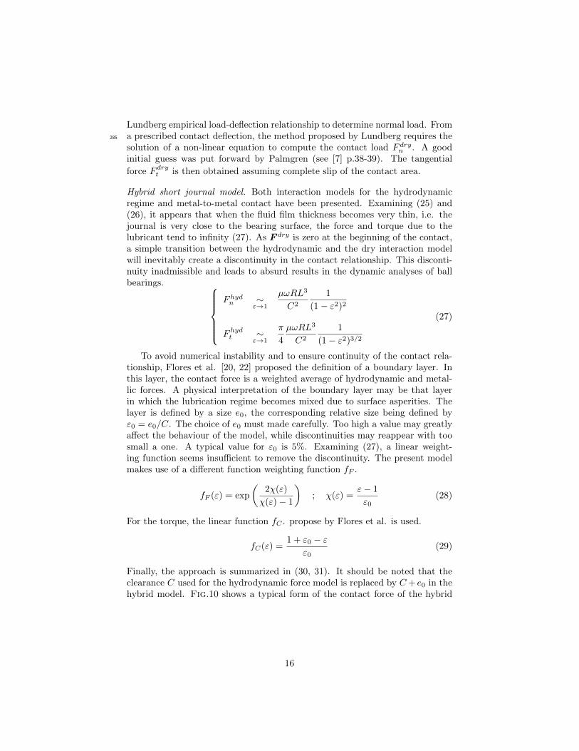
The load distribution on rolling elements and the corresponding contactangle are plotted in Fig.16. The high value of moment load leads to a large390
variation of contact load and contact angle. For both inner and outer contacts,variation in contact angle is about 15 leading to an excessive rolling elementexcursion. Such a circumferential excursion results in strong interactions withthe cage and cage motion is thereby affected.
0
1
2
34
567
8
9
10
11
12
13
1415
16 1718
19
20
21
01000
20003000
Loads (N)Inner raceOuter race
0
1
2
34
567
8
9
10
11
12
13
1415
16 1718
19
20
21
010
2030
40
Contact angle (deg)
Figure 16: Rolling element load distribution and corresponding contact angle, quasi-staticsimulation, case (b)
The cage centre trajectory is plotted in Fig.17(a). It can be observed that395
the cage is constantly crushed against the outer race. The contact remainswithin a well defined area. The cage centre position slightly exceeds the radialplay, so metal-to-metal contact occurs. Here, the utility of the continuous con-tact force model for the hybrid short journal model is highlighted. Thus, theequations of motion can be integrated even with an implicit scheme. If the cage400
trajectory obviously shows a malfunction of the ball bearing, with a relativevariation about 1.4%, the cage rotation velocity fails to provide any valuableinformation on the dynamic performance of the ball bearing (see Fig.17(b)).
The inner race again exhibits a quasi-periodic motion in the horizontal andvertical directions (see Fig.18(a)). The perturbation of the oscillating motion405
is of the same order of magnitude as in the first case. In the axial direction, theinner ring rapidly approaches to the point (0.3425, 0.) with a gentle oscillationaround it. In the phase portrait of the ball separator displayed in Fig.18(b),the almost constant radial position of the cage mass centre is also visible. Inthe axial direction however, the cage exhibits oscillatory behaviour around the410
axial position z = 0.2mm. In this model, since the hybrid short journal modelproduces no axial force, the axial motion of the cage is induced only by ballimpacts on pockets. Thus, in the axial direction, the absence of viscous forcesexplains this oscillatory behaviour.
25

−0.2 −0.1 0.0 0.1 0.2
xcage(mm)
−0.2
−0.1
0.0
0.1
0.2
ycage(mm
)
Radial cage center trajectory
Ocage(t = 0)
Ocage(t)
Ocage(t = tf )
Radial play
(a) Trajectory of the cage mass centre
0 5 10 15 20 25 30 35
Inner race revolution
1370
1375
1380
1385
Rot
atio
nve
loci
ty(revmin−
1)
Time evolution of rotation velocity of Cage
(b) Evolution over time of the cage velocity
Figure 17: Trajectory and rotation velocity of the cage, case (b)
−0.005 0.000 0.005Horizontal displacement (mm)
−2
0
2
4
Hor
izon
talv
eloc
ity
(mms−
1)
−0.045 −0.040Vertical displacement (mm)
−5
0
5
Ver
tica
lvel
ocit
y(mms−
1)
0.342 0.343Axial displacement (mm)
0
Axi
alve
loci
ty(mms−
1)
(a) Phase portrait of the inner ring
−0.20 −0.15 −0.10 −0.05 0.00Horizontal displacement (mm)
−50
0
50
Hor
izon
talv
eloc
ity
(mms−
1)
−0.20 −0.15 −0.10 −0.05 0.00Vertical displacement (mm)
−50
0
Ver
tica
lvel
ocit
y(mms−
1)
0.0 0.2 0.4Axial displacement (mm)
−200
−100
0
100
Axi
alve
loci
ty(mms−
1)
(b) Phase portrait of the cage
Figure 18: Phase portrait of inner ring and cage, case (b)
26

0
200
400
600
Forc
eF
(N)
Time evolution of cage outer race interaction
0
1
2
3
Torq
ueC
(Nm
)
0 10 20 30
Inner race revolution
0.0
0.2
0.4
0.6
0.8
1.0
Rel
ativ
eec
cent
rici
ty
Figure 19: Evolution over time of conformal contact data between cage and outer race, case(b)
27
With regard to cage interactions, contact loads at the guide lands are severe415
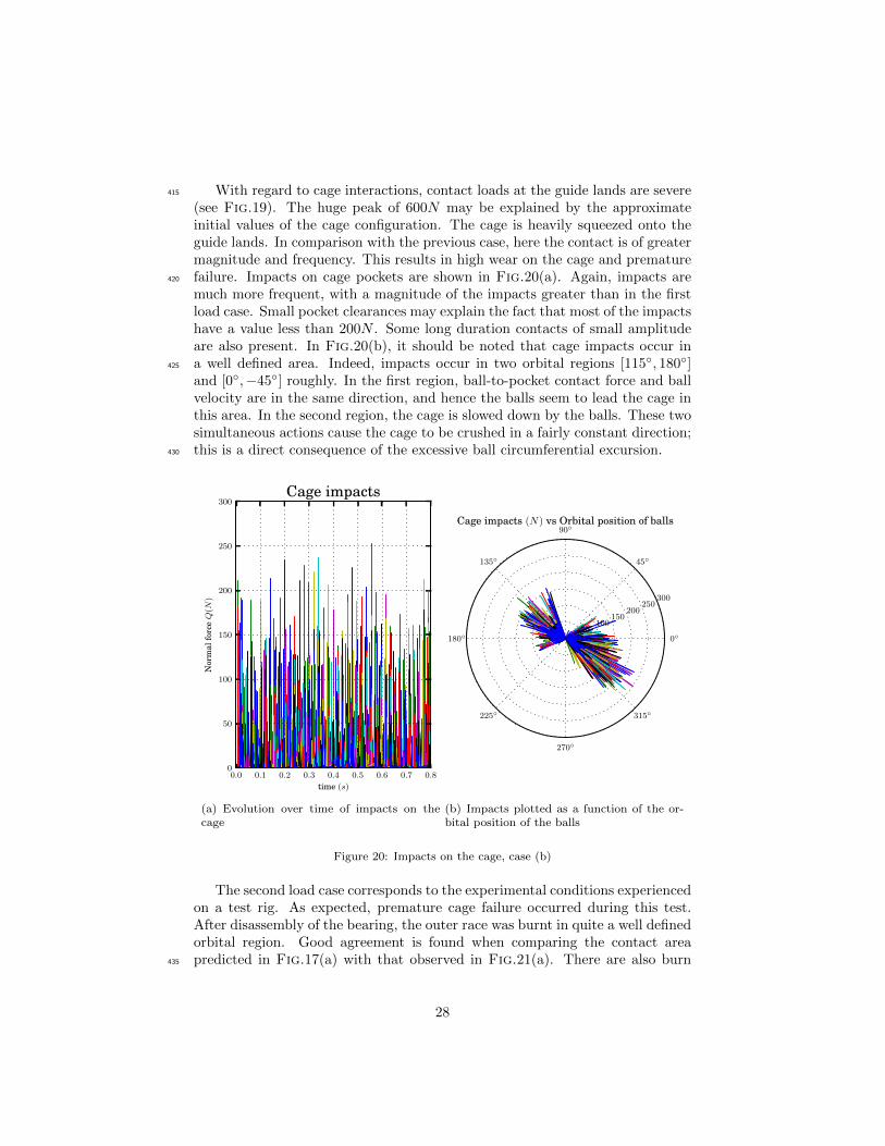
(see Fig.19). The huge peak of 600N may be explained by the approximateinitial values of the cage configuration. The cage is heavily squeezed onto theguide lands. In comparison with the previous case, here the contact is of greatermagnitude and frequency. This results in high wear on the cage and prematurefailure. Impacts on cage pockets are shown in Fig.20(a). Again, impacts are420
much more frequent, with a magnitude of the impacts greater than in the firstload case. Small pocket clearances may explain the fact that most of the impactshave a value less than 200N . Some long duration contacts of small amplitudeare also present. In Fig.20(b), it should be noted that cage impacts occur ina well defined area. Indeed, impacts occur in two orbital regions [115, 180]425
and [0,−45] roughly. In the first region, ball-to-pocket contact force and ballvelocity are in the same direction, and hence the balls seem to lead the cage inthis area. In the second region, the cage is slowed down by the balls. These twosimultaneous actions cause the cage to be crushed in a fairly constant direction;this is a direct consequence of the excessive ball circumferential excursion.430
0.0 0.1 0.2 0.3 0.4 0.5 0.6 0.7 0.8
time (s)
0
50
100
150
200
250
300
Nor
mal
forc
eQ
(N)
Cage impacts
(a) Evolution over time of impacts on thecage
0
45
90
135
180
225
270
315
50100
150200
250300
Cage impacts (N) vs Orbital position of balls
(b) Impacts plotted as a function of the or-bital position of the balls
Figure 20: Impacts on the cage, case (b)
The second load case corresponds to the experimental conditions experiencedon a test rig. As expected, premature cage failure occurred during this test.After disassembly of the bearing, the outer race was burnt in quite a well definedorbital region. Good agreement is found when comparing the contact areapredicted in Fig.17(a) with that observed in Fig.21(a). There are also burn435
28

marks all around the cage (see Fig.21(b)). A slight asymmetry in the burnmarks is observed between the cage sides. This asymmetry may be explainedby the non-centred axial position. Indeed, the cage axial position varies around0.2mm (see Fig.18(b)).
Maximumcontact angle
Contact area
(a) Outer race (b) Cage
Figure 21: Contact area on ball bearing components
Finally, owing to the high value of moment load, the ball bearing exhibits440
an obvious dysfunction. The premature failure was accurately predicted by thedynamic numerical analysis and confirmed by experimental observations. Fromthe author’s experience, without the hybrid short journal, the discontinuity inthe contact force model leads to an absurd cage trajectory. On the other hand,if the viscoelastic hinge joint that constrains the inner race is removed, the cage445
is still constantly crushed against the outer race but the contact area movesall around the outer race. Thus, the viscoelastic hinge joint and the hybridshort journal model appear essential in managing the dynamic analysis of a ballbearing under such severe load conditions.
29

6. Conclusion450
An approach for predicting the internal behaviour of ball bearings under highmoment loads has been presented and discussed throughout this paper. The ballbearing model proposed is not limited to planar systems. Several phenomenasuch as contact deformation, internal clearance, cage run-out and elastohydro-dynamic lubrication are taken into account. Lubricant traction is computed455
assuming non-Newtonian behaviour of the lubricant and isothermal conditions.In order to manage dynamic analysis of ball bearings under such specific andsevere loading, the configuration dependence of the shaft-to-inner-ring force isconsidered by means of an equivalent viscoelastic hinge joint. Rigidity param-eters of the equivalent joint are identified via global finite element simulations460
and damping parameters are assumed proportional to rigidity parameters. Also,a hybrid short journal model which considers the transition from hydrodynamicto metal-to-metal contact forces has been developed in order to model cage toguide lands contact. The equations of motion are derived using a multibody dy-namic formalism and integrated using the unconditionally stable, implicit hht465
scheme.A ball bearing subjected to two different values of moment is chosen as an
example to demonstrate the capability of the methodology presented in thispaper. With a moderate value of moment load, the ball bearing functionscorrectly, especially in terms of the dynamic behaviour of the cage. In the second470
load case, the value of the moment load is so high that excessive cage interactionoccurs. The cage is crushed against the guide lands in a approximately fixedlocation. Cage pocket impacts are more frequent and violent. The magnitudeof these impacts appears, however, to be limited by cage pocket clearances. Itis also shown that in this case, variations in cage rotational speed are not well475
correlated with incorrect operation of the ball bearing. The second load casehas been experienced on a test rig and numerical results are compared withexperimental observations. Good agreement is found between the predictedcage to outer race contact location and burn marks seen on the outer race afterdisassembly of the ball bearing.480
Although cage interactions are overestimated owing the assumptions of arigid cage, the methodology presented here provides valuable information aboutthe dynamic behaviour of ball bearings even in cases of severe loading. Inparticular, localized non-linear phenomena such as ball skidding, cage pocketimpacts or cage instability are accurately predicted by this approach.485
Acknowledgement
The authors would like to thank the Airbus Helicopters Company for per-mission to publish this work.
[1] L. Zamponi, E. Mermoz, J.-M. Linares, J.-M. Sprauel, Impact of geomet-rical defects on bearing assemblies with integrated raceways in aeronauti-490
cal gearboxes, Mechanism and Machine. Theory 44 (6) (2009) 1108–1120.doi:10.1016/j.mechmachtheory.2008.10.005.
30
[2] A. B. Jones, A General Theory for Elastically Constrained Ball and RadialRoller Bearings Under Arbitrary Load and Speed Conditions, Journal ofFluids Engineering 82 (1960) 309–320. doi:10.1115/1.3662587.495
[3] T. A. Harris, M. N. Kotzalas, Rolling bearing analysis, J Wiley, New York,2001.
[4] C. Walters, The dynamics of ball bearings, Journal of Lubrication Tech-nology 93 (1) (1971) 1–10. doi:10.1115/1.3451516.
[5] J. Kannel, S. Bupara, A simplified model of cage motion in angular contact500
bearings operating in the EHD lubrication regime, Journal of Tribology 100(1978) 395–403. doi:10.1115/1.3453196.
[6] C. Meeks, L. Tran, Ball bearing dynamic analysis using computermethods—part I: analysis, Journal of Tribology 118 (1996) 52–58. doi:
10.1115/1.2837092.505
[7] P. K. Gupta, Advanced dynamics of rolling elements, Springer-Verlag, 1984.
[8] P. K. Gupta, On the Geometrical Imperfections in Ball Bearings, Journalof Tribology 110 (1988) 19–25. doi:10.1115/1.3261567.
[9] N. Tandon, A. Choudhury, An analytical model for the prediction of thevibration response of rolling element bearings due to a localized defect,510
Journal of Sound and Vibration 205 (3) (1997) 275–292. doi:http://dx.
doi.org/10.1006/jsvi.1997.1031.
[10] S. P. Harsha, Nonlinear dynamic response of a balanced rotor sup-ported by rolling element bearings due to radial internal clearance ef-fect, Mechanism and Machine Theory 41 (2006) 688–706. doi:10.1016/515
j.mechmachtheory.2005.09.003.
[11] S. P. Harsha, Nonlinear dynamic analysis of rolling element bearings due tocage run-out and number of balls, Journal of Sound and Vibration 289 (1-2)(2006) 360–381. doi:10.1016/j.jsv.2005.02.021.
[12] C. Nataraj, S. P. Harsha, The effect of bearing cage run-out on the non-520
linear dynamics of a rotating shaft, Communications in Nonlinear Scienceand Numerical Simulation 13 (4) (2008) 822–838. doi:10.1016/j.cnsns.2006.07.010.
[13] S. P. Harsha, K. Sandeep, R. Prakash, Non-linear dynamic behaviors ofrolling element bearings due to surface waviness, Journal of Sound and Vi-525
bration 272 (3–5) (2004) 557–580. doi:10.1016/S0022-460X(03)00384-5.
[14] B. Changqing, X. Qingyu, Dynamic model of ball bearings with internalclearance and waviness, Journal of Sound and Vibration 294 (1-2) (2006)23–48. doi:10.1016/j.jsv.2005.10.005.
31
[15] A. Leblanc, D. Nelias, C. Defaye, Nonlinear dynamic analysis of cylindrical530
roller bearing with flexible rings, Journal of Sound and Vibration 325 (1-2)(2009) 145–160. doi:10.1016/j.jsv.2009.03.013.
[16] T. Yao, Y. Chi, Y. Huang, Research on Flexibility of Bearing Rings forMultibody Contact Dynamics of Rolling Bearings, Procedia Eng. 31 (2011)(2012) 586–594. doi:10.1016/j.proeng.2012.01.1071.535
[17] A. Lioulios, I. Antoniadis, Effect of rotational speed fluctuations on thedynamic behaviour of rolling element bearings with radial clearances, Int.J. Mech. Sci. 48 (8) (2006) 809–829. doi:10.1016/j.ijmecsci.2006.03.006.
[18] A. Shabana, Dynamics of Multibody Systems, Cambridge University Press,540
2005.
[19] M. Geradin, A. Cardona, Flexible multibody dynamics: a finite elementapproach, John Wiley, 2001.
[20] P. Flores, J. Ambrosio, J. P. Claro, Dynamic Analysis for Planar MultibodyMechanical Systems with Lubricated Joints, Multibody System Dynamics545
12 (1) (2004) 47–74. doi:10.1023/B:MUBO.0000042901.74498.3a.
[21] P. Flores, H. M. Lankarani, Spatial rigid-multibody systems with lubricatedspherical clearance joints: modeling and simulation, Nonlinear Dynamics60 (1-2) (2009) 99–114. doi:10.1007/s11071-009-9583-z.
[22] P. Flores, J. Ambrosio, J. Claro, H. Lankarani, C. Koshy, Lubricated rev-550
olute joints in rigid multibody systems, Nonlinear Dynamics 56 (3) (2009)277–295. doi:10.1007/s11071-008-9399-2.
[23] Q. Tian, Y. Zhang, L. Chen, J. J. Yang, Simulation of planar flexiblemultibody systems with clearance and lubricated revolute joints, NonlinearDynamics 60 (4) (2009) 489–511. doi:10.1007/s11071-009-9610-0.555
[24] Q. Tian, Y. Zhang, L. Chen, P. Flores, Dynamics of spatial flexible multi-body systems with clearance and lubricated spherical joints, Computers &Structures 87 (13-14) (2009) 913–929. doi:10.1016/j.compstruc.2009.
03.006.
[25] L. Xu, Y. Yang, Y. Li, C. Li, S. Wang, Modeling and analysis of pla-560
nar multibody systems containing deep groove ball bearing with clear-ance, Mechanism and Machine Theory 56 (2012) 69–88. doi:10.1016/
j.mechmachtheory.2012.05.009.
[26] L.-x. Xu, Y.-g. Li, An approach for calculating the dynamic load of deepgroove ball bearing joints in planar multibody systems, Nonlinear Dynamics565
70 (3) (2012) 2145–2161. doi:10.1007/s11071-012-0606-9.
32

[27] Z. Qi, G. Wang, Z. Zhang, Contact analysis of deep groove ball bear-ings in multibody systems, Multibody System Dynamics.doi:10.1007/s11044-014-9412-0.
[28] L.-x. Xu, Y.-g. Li, Modeling of a deep-groove ball bearing with waviness570
defects in planar multibody system, Multibody System Dynamicsdoi:10.1007/s11044-014-9413-z.
[29] L. E. Stacke, D. Fritzson, P. Nordling, BEAST—a rolling bearing simu-lation tool, Proceedings of the Institution of Mechanical Engineers, PartK: Journal of Multi-body Dynamics 213 (2) (1999) 63–71. doi:10.1243/575
1464419991544063.
[30] I. Nakhimovski, Contributions to the Modeling and Simulation of Mechan-ical Systems with Detailed Contact Analyses, Ph.D. thesis, Linkpings uni-versity (2006).
[31] C. Bovet, J.-M. Linares, L. Zamponi, E. Mermoz, Multibody modeling of580
non-planar ball bearings, Mechanics & Industry. 14 (5) (2013) 335–345.doi:10.1051/meca/2013075.
[32] G. Nijenbanning, C. H. Venner, H. Moes, Film thickness in elastohy-drodynamically lubricated elliptic contacts, Wear 176 (1994) 217–229.doi:http://dx.doi.org/10.1016/0043-1648(94)90150-3.585
[33] C. H. Venner, Multilevel solution of the EHL line and point contact prob-lems, Ph.D. thesis, University of Twente (1991).
[34] B. Jacod, Friction in elasto-hydrodynamic lubrication, Ph.D. thesis, Uni-versity of Twente (2002).
[35] L. Zamponi, E. Mermoz, J.-M. Linares, Etudes des methodes de calcul590
des pressions de contact dans les roulements a pistes integrees des boıtesde transmission aeronautiques, Mecanique & Industries 8 (2007) 567–575.doi:10.1051/meca:2007081.
[36] O. Bauchau, L. Trainelli, The vectorial parameterization of rotation, Non-linear Dynamics 32 (1) (2003) 71–92. doi:10.1023/A:1024265401576.595
[37] M. Geradin, A. Cardona, Kinematics and dynamics of rigid and flexiblemechanisms using finite elements and quaternion algebra, ComputationalMechanics 4 (1989) 115–135. doi:10.1007/BF00282414.
[38] H. M. Hilber, T. Hughes, R. L. Taylor, Improved numerical dissipationfor time integration algorithms in structural dynamics, Earthquake Engi-600
neering & Structural Dynamics 5 (3) (1977) 283–292. doi:10.1002/eqe.
4290050306.
[39] O. Bauchau, On the Modeling of Friction and Rolling in Flexible Multi-Body Systems, Multibody System Dynamics 3 (3) (1999) 209–239. doi:
10.1023/A:1009883931415.605
33

[40] K. Johnson, Contact Mechanics, Cambridge University Press, 1987.
[41] S. Yasutomi, S. Bair, W. Winer, An application of a free volume model tolubricant rheology I—dependence of viscosity on temperature and pressure,Journal of Tribology 106 (1984) 291–302. doi:10.1115/1.3260907.
[42] O. Pinkus, B. Sternlicht, Theory of hydrodynamic lubrication by Oscar610
Pinkus and Beno Sternlicht, New York : McGraw-Hill, 1961.
[43] J. Frene, D. Nicolas, B. Degueurce, D. Berthe, M. Godet, Hydrodynamiclubrication: bearings and thrust bearings, Vol. 33, Elsevier, 1997.
[44] P. K. Gupta, Dynamic loads and cage wear in high-speed rolling bearings,Wear 147 (1) (1991) 119–134. doi:10.1016/0043-1648(91)90123-C.615
34


![[Credit] scoring : predicting, understanding and ... · [CREDIT] SCORING: PREDICTING, UNDERSTANDING AND EXPLAINING CONSUMER BEHAVIOUR By ROBERT HAMILTON ABSTRACT Th1s thesis stems](https://img.pdfslide.us/doc/110x75/5c6a4bd809d3f20f298c6297/credit-scoring-predicting-understanding-and-credit-scoring-predicting.jpg)