Embed Size (px)
Citation preview

Vol. 2 No. 1, Feb. 2005 CHINA FOUNDRY
An application of differential interference contrastin metallographic examination
*Xiang CHEN , Yanxiang LI(Department of Mechanical Engineering, Tsinghua University, Beijing 100084, P. R. China)
Abstract: As one of the most exciting inspection and powerful analysis methods in modern materials metallographicexaminations, the difference interference contrast (DIC) method has many advantages, including relatively lowrequirement for specimen preparation, obvious relief senses observed under microscope. Details such as fine structuresor defects that are not or barely visible in incident-light bright field, could be easily revealed and thus make materialsanalysis more reliable. Differential interference contrast produces an image that can be readily manipulated using digitaland video imaging techniques to further enhance contrast. But, studies of material metallography based on DIC methodhave rarely carried out. Based on the fundamental principle of the DIC method combing with the computer imageanalysis, applications of DIC method in materials metallographic examination were investigated in this study.
Keywords: difference interference contrast method;metallographic examination; and image analysis
CLC number: TG14, TG115.2 Document: A Article ID: 1672-6421(2005) 01-0014-07
1. IntroductionThe difference interference contrast (DIC) method is
one of the most exciting inspection and powerful analysis
methods in modern materials metallographic exami-
nations [1], which has many advantages. Specimens
preparation is relatively simple. For certain specimens,
their microstructure could be observed without etching
under the microscope by using the DIC method as the
polished specimen surface is preserved. The obser-
vation of the specimen surface via the microscope has
obvious accidented senses, taking the form of relief. The
relative locations of different features in a specimen could
be distinguished readily. The particles, crackles, caves,
slopes, valleys, and other discontinuities could be judged
correctly, with the improved accuracy of the metallo-
graphic examination, in which the contrast of the features
are enhanced. With the DIC method, details such as
some fine structures or defects that are not or barely
visible in incident-light bright field could be easily
observed. The DIC method based on the traditional
polarized light with a polarizer and specialized beam
splitting prisms, named Wollaston or Nomarski prisms,
adds pseudo-color which improves visual contrast
between different phases. In addition, differential
interference contrast produces an image that can be easily
manipulated using digital and video imaging techniques to
further enhance contrast.
Like polarized light, DIC was also primarily developed
as an analytical method to determine various optical
properties of crystals. Thus, it is a method of measure-
ment, requiring specific knowledge and specially-
designed microscopes of considerable complexity. Appro-
priate applications of the DIC method can yield fine
details of microstructure.
Differential interference contrast has found wide
application in biology due to its simplicity in use and
emergency of commercially-available microscopes.
However, little study of materials metallography based
on the DIC method has been carried out. This is because
most laboratories for materials research presently are not
equipped with metallographic microscopes including DIC
optical components. Few materials researchers have
realized the potential and capability of the DIC method
microstructure analysis.
The basic principles of the DIC method are introduced
based on the Neophot32 microscope in this paper.
Combining with the technology of computer image
analysis, applications of the DIC method in materials
metallographic examination are presented.
2. The fundamental principles of DICMethod
The DIC method is based on the theory of differential
interference contrast (DIC) by using a Nomarski prism in
the polarized light fields. The optical path is very sensitive
to small height difference of light interference in
nanometer size.
The basic DIC system, first devised by Francis Smith in
*Xiang CHEN: Associate professor, engaged in research of materialsprocessingE-mail: xchen @ mail.tsinghua.edu.cn
[Received date] 2004-11-16; [Accepted date] 2004-12-06

Vol. 2 No. 1 An application of differential interference contrast
1955 [2] ,is a modified polarized light microscope with two
additional Wollaston prisms added, one at the front focal
plane of the condenser and the second at the rear focal
plane of the objective. Several years later, Georges
Nomarski, modified the standard Wollaston prism
configuration to enable these exceedingly thin optical
components to be physically located away from the
conjugate planes of an aperture.
The optical components required for differential inter-
ference contrast microscopy do not mask or otherwise
obstruct the objective and condenser apertures, thus
enabling the instrument to be employed at full numerical
aperture. The result is a dramatic improvement in
resolution (particularly along the optical axis), elimination
of halo artifact [2]. Moreover, differential interference
contrast can produce images that can be easily
manipulated using digital and video imaging techniques to
further treatments or quantitative analysis.
2.1 The basic components of DIC method
In general, only four basic components are required to
configure a research or standard laboratory bright field
microscope for observation in differential interference
contrast: linear polarizer, sensitive wave plate (also
termed λ-a compensator), DIK module and analyzer.
Linear polarizer is inserted into the optical pathway
between the microscope light port (or anywhere after the
illumination source collector lens) and the condenser lens
assembly. This component is designed to produce the
necessary plane-polarized light for interference imaging.
The vibration plane transmission axis for the electric
vector component is oriented in an East-West direction
(right to left when standing in front of the microscope),
typical of a standard polarized light microscope. Some
differential interference contrast designs incorporate a
rotating polarizer combined with a quarter-wavelength
retardation plate at this position in the microscope [3].
DIK module is provided with a Nomarski prism which
consists of two prisms at right angle slidable in its
working position and two set-screws. By actuating the
smaller set-screw towards the optical axis of the
microscope, an optimum position of the prism relative to
the objective's exit pupil; while actuating the larger
set-screw, the relative position of the two prisms of the
Nomarski prism resulting a slight change of the optical
path difference that producing the interference effect
could be adjusted and the contrast could be varied
delicately. The Nomarski prism separates the polarized
light emanating from the polarizer into it. Incident
wavefronts of plane-polarized light are split (or sheared)
into mutually perpendicular (orthogonal) polarized
components (termed ordinary and extraordinary
wavefronts) by the Nomarski prism, and then pass through
the specimen. The material of the prism is normally
quartz.
Analyzer, the second linear polarizer, is installed
behind the Nomarski prism, usually in an intermediate
tube between the microscope nosepiece and observation
(eyepiece) tubes. Termed an analyzer, this polarizing
element is positioned in the optical pathway before the
tube lens (for infinity-corrected microscopes) and image
plane. The analyzer is oriented with the transmission axis
of the electric field vector perpendicular (North-South) to
that of the substage polarizer. Components of circular and
elliptically polarized light arriving from the objective
prism pass through the analyzer and subsequently undergo
interference to generate the DIC image at the microscope
intermediate image plane [3].
Because only the second series have rich hue where the
optical path difference is between 560 and 1 120 nm.
Normally, a piece of full-wave plate should be added in
the optical path of polarized microscope. This full-wave
plate can produce an optical path difference of 576 nm.
Regardless of the polarization state changes, it can extend
the wide range of color contrast nuances gradually and
always produce bright color changes. This full-wave plate
is called the sensitive plate or λ-a compensator.
2.2 The imaging mechanisms of DIC method
Fig. 1 presents the basic Nomarski prism differential
interference contrast device. When light passes through an
optically homogeneous medium, it produces one
refraction of light. But when it passes through a
non-homogeneous material, the refracted light will be
split into two bundles, which is called the birefringence,
or double refraction. The vibration directions of the two
lines produced by the birefringence are perpendicular to
each other. Their speed is different and their refractive
index is different [5].
When a bundle of parallel light passing through the
polarizer, it will become plane-polarized light. Then the
light after polarizing passes through the DIC prism, it
splits into two lights. One, being called ordinary light or o
light, propagates along its original direction. The other,
being called extraordinary light or e light, deviates slightly
from its original direction. Both the o and e lights
produced by the birefringence are polarized lights.
CHINA FOUNDRY
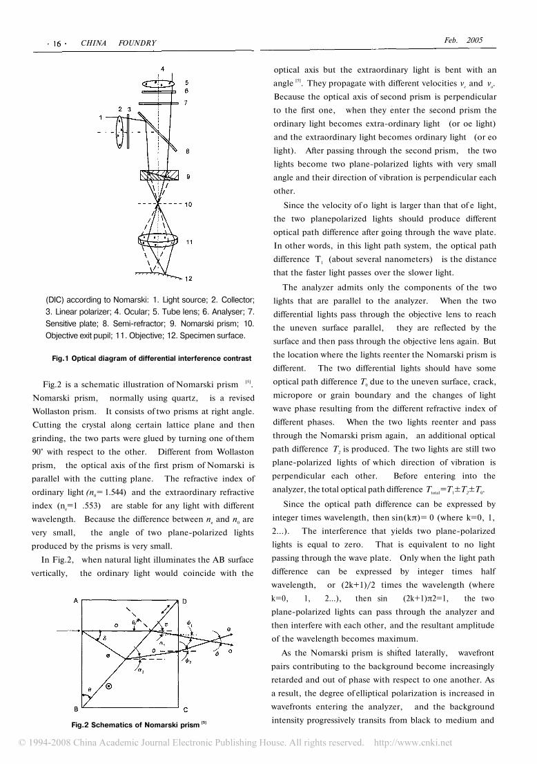
(DIC) according to Nomarski: 1. Light source; 2. Collector;
3. Linear polarizer; 4. Ocular; 5. Tube lens; 6. Analyser; 7.
Sensitive plate; 8. Semi-refractor; 9. Nomarski prism; 10.
Objective exit pupil; 11. Objective; 12. Specimen surface.
Fig.1 Optical diagram of differential interference contrast
Fig.2 is a schematic illustration of Nomarski prism [5].
Nomarski prism, normally using quartz, is a revised
Wollaston prism. It consists of two prisms at right angle.
Cutting the crystal along certain lattice plane and then
grinding, the two parts were glued by turning one of them
90° with respect to the other. Different from Wollaston
prism, the optical axis of the first prism of Nomarski is
parallel with the cutting plane. The refractive index of
ordinary light (n0= 1.544) and the extraordinary refractive
index (ne=1 .553) are stable for any light with different
wavelength. Because the difference between ne and n0 are
very small, the angle of two plane-polarized lights
produced by the prisms is very small.
In Fig.2, when natural light illuminates the AB surface
vertically, the ordinary light would coincide with the
Fig.2 Schematics of Nomarski prism [5]
Feb. 2005
optical axis but the extraordinary light is bent with an
angle [5]. They propagate with different velocities ve and vo.
Because the optical axis of second prism is perpendicular
to the first one, when they enter the second prism the
ordinary light becomes extra-ordinary light (or oe light)
and the extraordinary light becomes ordinary light (or eo
light). After passing through the second prism, the two
lights become two plane-polarized lights with very small
angle and their direction of vibration is perpendicular each
other.
Since the velocity of o light is larger than that of e light,
the two planepolarized lights should produce different
optical path difference after going through the wave plate.
In other words, in this light path system, the optical path
difference T1 (about several nanometers) is the distance
that the faster light passes over the slower light.
The analyzer admits only the components of the two
lights that are parallel to the analyzer. When the two
differential lights pass through the objective lens to reach
the uneven surface parallel, they are reflected by the
surface and then pass through the objective lens again. But
the location where the lights reenter the Nomarski prism is
different. The two differential lights should have some
optical path difference T0 due to the uneven surface, crack,
micropore or grain boundary and the changes of light
wave phase resulting from the different refractive index of
different phases. When the two lights reenter and pass
through the Nomarski prism again, an additional optical
path difference T2 is produced. The two lights are still two
plane-polarized lights of which direction of vibration is
perpendicular each other. Before entering into the
analyzer, the total optical path difference Ttotal=T1±T2±T0.
Since the optical path difference can be expressed by
integer times wavelength, then sin(kπ)= 0 (where k=0, 1,
2...). The interference that yields two plane-polarized
lights is equal to zero. That is equivalent to no light
passing through the wave plate. Only when the light path
difference can be expressed by integer times half
wavelength, or (2k+1)/2 times the wavelength (where
k=0, 1, 2...), then sin (2k+1)π2=1, the two
plane-polarized lights can pass through the analyzer and
then interfere with each other, and the resultant amplitude
of the wavelength becomes maximum.
As the Nomarski prism is shifted laterally, wavefront
pairs contributing to the background become increasingly
retarded and out of phase with respect to one another. As
a result, the degree of elliptical polarization is increased in
wavefronts entering the analyzer, and the background
intensity progressively transits from black to medium and

Vol. 2 No. 1 An application of differential interference contrast
lighter shades of gray. So as actuating the larger set-screw
of the DIK module, the relative displacement of the two
prisms of the Nomarski prism is generated and a pseudo
three-dimensional relief image (where regions of
increasing optical path difference (sloping phase
gradients) appear much brighter (or darker), and those
exhibiting decreasing path length appear in reverse) could
be observed from the ocular (seen in Fig.3). The
interference effect is zeroth-order interference now
(according to the order of interference color and content
of brilliance, the interference color can be divided into
four series), and the dark shadow is often termed
zero-order gray.
Different interference color corresponds to different
optical path difference for illuminating parallel or
orthogonal polarized light [5]. The range of optical path
difference is between 0 and 1 680 nm. According to the
order of interference color and content of brilliance, the
interference color can be divided into four series (Table 1).
Fig.3 The relief morphology of high manganese steel (Mn13)
Table 1 The interference color series
from dark to steel gray, blue gray, white,
yellow-white, bright-yellow, orange- yellow,
red and purple-red
from purple to dark blue, sky blue, and green,yellow-green, yellow-orange and purple-red
from purple to blue, green-blue, sea green,
green-yellow and lilac
from purple-gray to cyan-gray, green-gray, nattierblue-green, filbert- green and senior white
Because the sensitive plate or λ-a compensator is added
before the analyzer in the optical path of the microscope,
and can produce an optical path difference of 576 nm
(about a wavelength), the interference color order could
be extended from the zeroth-order series to the second
order series. When the optical path difference is zero, the
interference color is dark. If the optical path difference
increases gradually, the interference color changes from
dark to steel gray, blue gray, yellow white, bright yellow,
orange-yellow, red, purple, dark blue, sky blue, green,
yellow green, yellow, orange, purplish red, violet, blue,
green blue, sea blue, green, yellow, blood red, lilac, gray
blue, and senior white (Fig.4).
Because the optical path difference increases
continuously, the above order of interference color cannot
be changed. The transition between colors is gradually.
There is no significant boundary line. The higher the
order, the less distinct the boundaries.

CHINA FOUNDRY Feb. 2005
Fig.4 Colorful relief microstructure image with different optical path difference for AI-7Si Alloys
after grain refinement
3. Applications of DIC in metallographic
examinationWith the DIC method, certain features such as structure
details or defects that are not or barely visible in
incident-light bright field could be easy to be judged and
thus make materials characterization reliable.
The development of modern material science and
technology requires detailed depiction of metallographic
microstructure and accurate statistical analysis to the
microstructure characteristic parameters, such as
morphology of phases, quantity, distribution, phase size,
phase area, etc. But the quality of the digital pictures
captured by the digital devices (such as CCD, digital
camera, etc.) depends greatly on the preparation of the
sample in traditional bright fields. Also different phases in
microstructure are shown at very close grey levels in
traditional bright fields, which could result in great errors
of measurementss in quantitative metallography.
Equipped with the differential interference contrast
method, researchers could observe specific details of
specimens that is not apparent on observed images
captured by other methods.
3.1 Observation of fine structures
Fig. 5 shows the microstructure of a WC embedded
coating on a machine tools fabricated by laser cladding
method. The fine structure of the WC particles, such as
their growth steps and cavities, can be distinguished
clearly by the DIC method, while the WC phases are
presented in white and the cavities are in black dots
apparently.
Fig.6 shows the microstructure of Ni3Al produced by
the method of laser controlled synthesis reaction
(incompact powder system, the scanning power of the
laser is about 900 W, the scanning speed of the laser is
about 2 mm/s). Observed in the bright field, the black
phase is α-Ni, and the white phase presented in the form
of petals is the eutectic structure of Ni3Al and α-Ni. No
additional detailed information about this microstructure
is obtained. However, while observed in the DIC, the
growth sequence of the eutectic structure is presented.
Fig.5 The fine structure of the laser cladding WC embedded coating

Vol. 2 No. 1 An application of differential interference contrast
Fig.6 The fine structure of Ni3AI produced by the method of laser controlled synthesis reaction
3.2 Quantitative metallography of microstructure
Fig.7 is the microstructure morphology of the gray iron
(large white phase is iron phosphide eutectic in bright
field). When calculating the amount of iron phosphide
eutectic in the gray iron, the ferrite in pearlite may be
counted in as it is present in a similar color with the iron
phosphide eutectic in bright field, and thus a systematic
error can be introduced. But in DIC, the iron phosphide
eutectic is separated by a distinctive color with the ferrite
in pearlite. Hence, the quantitative analysis of the iron
phosphide eutectic becomes more accurate.
Fig. 8 is the quantitative metallography of the amount of
ferrite in hypoeutectic Fe-C alloy fabricated by powder
metallurgy method. In bright field, the color of the ferrite
in pearlite is so close to the color of the free ferrite that a
bias error can introduced when calculating the amount of
ferrite by image analyzer. But in DIC, the free ferrite is
rendered in evident color that can be distinguished easily
with the ferrite in pearlite.
Fig.7 Iron phosphide eutectic in the gray iron
Fig.8 Quantitative metallography of the amount of ferrite in hypoeutectic Fe-C alloy fabricated by powder metallurgy method

CHINA FOUNDRY Feb. 2005
3.3 Calculation of height difference of the specimen
surfaces
Because the interference color is produced by the
optical path difference after the light illuminates the
surface and nothing other than by light source. The optical
path difference can be determined by the chromatograph
table. Therefore, it is possible to use the changes of
interference color to measure the height difference. Using
the DIC method, the height difference of the specimen
surface at mesoscopic level, such as the surface roughness
of the component parts after precision finishing, the
surface relief of martensite and bainite transformation and
plastic deformation of the materials, could be determined.
Suppose the phase height difference h of the specimen
surface is a stair step surface, it can be concluded from the
basic principle of DIC method that the optical path
difference A of a stair step surface produced by Nomarski
prism is twice the height of the step, that is Δ=2h. The
height difference determines the optical path difference
and the interference color (a chromatograph Table [6] is
plotted according to the optical path difference) or vice
versa. The hue change of interference color is clear. But,
the hue change of interference color can be used to
determine the height difference since the brightness and
saturation cannot reach the level of the light source. The
isoheight contour according to the hue change of
interference color of the DIC image can be plotted and the
relationship between the hue change of interference color
and height difference can be derived. J. Z. PAN and
D. B. ZHU [5] used the DIC method to examine the meso-
scopic detail of crack tip deformation field. Fig.9 is the
meso-scopic details of crack tip deformation field in DIC.
Fig.9 Mesoscopic details of crack tip deformation field in DIC [5]
4. ConclusionsAs one of the most exciting inspection and powerful
analysis methods in modern materials metallographic
examinations, the difference interference contrast (DIC)
method has many advantages. Due to relatively simple
requirement for specimen preparation, obvious relief
senses observed under microscope, details such as fine
structures or defects that are not or barely visible in
incident-light bright field, could be easily to be judged and
thus make materials analysis more reliable. Differential
interference contrast produces an image that can be easily
manipulated using digital and video imaging techniques to
further enhance contrast. Combining with the differential
interference contrast method, researchers could observe
specific fine microstructure about specimen that is not
apparent from observing images captured by conventional
methods. The potential of the DIC method has been
evidently demonstrated in modern metallographic
examinations.
References[1] Ying SHE, Liqi Yl and Huhobaterl. Modern Optical Microscope
[M].Beijing: Science Press, 1997 (in Chinese)
[2] B. M. Douglas, H. Jan, D. S. Edward, et al. Differentialinterference contrast fundamental concepts [EB]. http: //microscopy.fsu.edu/primer/techniques/dic/dicintro.html
[3] B. M. Douglas, R. S. Kenneth and Mortimer A. Differentialinterference contrast interactive java tutorials - DIC microscopecomponents and imaging mechanisms [EB]. http://microscopy.fsu.edu/primer/java/ dic/lightpaths/ index, html
[4] Danz Rainer and Gretscher Peter. C-DIC: a new microscopymethod for rational study of phase structures in incident lightarrangement [J]. Thin solid films, 2004, 462-463 (9): 257-262
[5] J. Z. PAN and D. B. ZHU. Mesoscopic details of crack tipdeformation field by application of differential interference
contrastmethod [J]. Theoretical and Applied Fracture Mechanics,2004,41(1-3):7-162
[6] Yeying SUN. Optical microscopic analysis [M]. Beijing: TsinghuaUniversity Press, 2003 (in Chinese)

![Quantitative differential interference contrast (DIC ... DIC v3.pdf2007. References: Title Microsoft PowerPoint - off-chip DIC v3.ppt [Compatibility Mode] Author Anne Created Date](https://img.pdfslide.us/doc/110x75/5f478857a1b54c464475ddfe/quantitative-differential-interference-contrast-dic-dic-v3pdf-2007-references.jpg)