Embed Size (px)
Citation preview
Hindawi Publishing CorporationInternational Journal of Antennas and PropagationVolume 2008, Article ID 456019, 10 pagesdoi:10.1155/2008/456019
Research ArticleAn Antenna-Theory Method for Modeling High-FrequencyRF Coils: A Segmented Birdcage Example
Xin Chen,1 Victor Taracila,2 Timothy Eagan,3 Hiroyuki Fujita,1, 4, 5 Xingxian Shou,1
Tanvir Baig,6 and Robert Brown1
1 Department of Physics, Case Western Reserve University, 10900 Euclid Avenue, Cleveland, OH 44106, USA2 GE Healthcare, Aurora, OH 44202, USA3 Philips Medical Systems, Highland Heights, OH 44143, USA4 Department of Radiology, University Hospitals of Cleveland, Cleveland, OH 44106, USA5 Quality Electrodynamics LLC, Mayfield Village, OH 44143-2336, USA6 Department of Physics, University of Dhaka, Dhaka 1000, Bangladesh
Correspondence should be addressed to Robert Brown, [email protected]
Received 2 August 2007; Revised 4 December 2007; Accepted 12 February 2008
Recommended by Stuart Crozier
We suggest that center-fed dipole antenna analytics can be employed in the optimized design of high-frequency MRI RF coilapplications. The method is illustrated in the design of a single-segmented birdcage model and a short multisegmented birdcagemodel. As a byproduct, it is shown that for a long single-segmented birdcage model, the RF field within it is essentially a TEMmode and has excellent planar uniformity. For a short shielded multisegmented birdcage model, the RF field is optimized with atarget-field approach with an average SAR functional. The planar homogeneity of the optimized RF field is significantly improvedcompared with that of a single-segmented birdcage model with the same geometry. The accuracy of the antenna formulae is alsoverified with numerical simulations performed via commercial software. The model discussed herein provides evidence for theeffectiveness of antenna methods in future RF coil analysis.
Copyright © 2008 Xin Chen et al. This is an open access article distributed under the Creative Commons Attribution License,which permits unrestricted use, distribution, and reproduction in any medium, provided the original work is properly cited.
1. INTRODUCTION
Radiofrequency (RF) field inhomogeneity has been a majorchallenge in today’s high-field magnetic resonance imaging(MRI) mainly due to the shortened RF wavelength in humantissue at higher frequencies. It has been shown [1] thatimage quality can be significantly affected. Recently, bothexperimental and theoretical work have been presented toimprove the RF field homogeneity, such as the TEM resonator[2, 3], closed-form analytical solutions [4–8], and numericalsimulations [9–11]. Techniques such as RF shimming [11]and parallel transmission [12] are applied to improve the RFfield homogeneity with a focus on the transmit coil array.Although theoretical progress has been made in analyzingthe experimental results, and RF field homogeneity can beimproved with various techniques, a better understandingof the relationship between the RF current sources andthe RF fields is still needed. A modeling control of thesource-field relationship can be used to optimize the RF
performance, much as has been done, for instance, in [13],for lower frequencies. Moreover, the specific absorption rate(SAR) is an important RF safety concern as more RF energytends to be deposited into human tissue in high-field MRIexperiments [14]. Although detailed numerical simulationshave been presented to analyze the SAR distribution in thehuman head within volume and surface coils [15, 16], thereis an absence of RF coil models that incorporate both RFfield and SAR calculation and optimization. In this paper,we show that analytic formulae found in antenna theory canbe applied with success in the optimized design of RF coils.It is well known that a static surface current distributionwhich is sinusoidal in the azimuthal direction on a surfaceof a cylinder produces a homogeneous static magnetic fieldeverywhere in the cylinder [17]. We find that in a highfrequency case, such sinusoidal current distribution canproduce magnetic field which is uniform in transverse planesand oscillates in the direction perpendicular to the transverseplane; thus transverse electromagnetic (TEM) mode can be
2 International Journal of Antennas and Propagation
l/2−l/2
−1
−0.8
−0.6
−0.4
−0.2
0
0.2
0.4
0.6
0.8
1
Nor
mal
ized
curr
ent
(a.u
.)
l = λ/4l = λ/2l = λ
l = 3λ/2l = 2λ
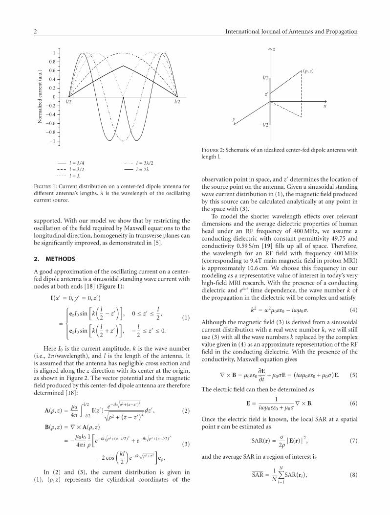
Figure 1: Current distribution on a center-fed dipole antenna fordifferent antenna’s lengths. λ is the wavelength of the oscillatingcurrent source.
supported. With our model we show that by restricting theoscillation of the field required by Maxwell equations to thelongitudinal direction, homogeneity in transverse planes canbe significantly improved, as demonstrated in [5].
2. METHODS
A good approximation of the oscillating current on a center-fed dipole antenna is a sinusoidal standing wave current withnodes at both ends [18] (Figure 1):
I(x′ = 0, y′ = 0, z′
)
=
⎧⎪⎪⎪⎪⎨
⎪⎪⎪⎪⎩
ezI0 sin[k(l
2− z′
)], 0 ≤ z′ ≤ l
2,
ezI0 sin[k(l
2+ z′
)], − l
2≤ z′ ≤ 0.
(1)
Here I0 is the current amplitude, k is the wave number(i.e., 2π/wavelength), and l is the length of the antenna. Itis assumed that the antenna has negligible cross section andis aligned along the z direction with its center at the origin,as shown in Figure 2. The vector potential and the magneticfield produced by this center-fed dipole antenna are thereforedetermined [18]:
A(ρ, z) = μ0
4π
∫ l/2
−l/2I(z′)
e−ik√ρ2+(z−z′)2
√ρ2 +
(z − z′
)2dz′, (2)
B(ρ, z) = ∇× A(ρ, z)
= −μ0I0
4πi1ρ
[e−ik
√ρ2+(z−l/2)2
+ e−ik√ρ2+(z+l/2)2
− 2 cos(kl
2
)e−ik
√ρ2+z2
]eϕ.
(3)
In (2) and (3), the current distribution is given in(1), (ρ, z) represents the cylindrical coordinates of the
x
y
z
z′
(ρ, z)
l/2
−l/2
Figure 2: Schematic of an idealized center-fed dipole antenna withlength l.
observation point in space, and z′ determines the location ofthe source point on the antenna. Given a sinusoidal standingwave current distribution in (1), the magnetic field producedby this source can be calculated analytically at any point inthe space with (3).
To model the shorter wavelength effects over relevantdimensions and the average dielectric properties of humanhead under an RF frequency of 400 MHz, we assume aconducting dielectric with constant permittivity 49.75 andconductivity 0.59 S/m [19] fills up all of space. Therefore,the wavelength for an RF field with frequency 400 MHz(corresponding to 9.4T main magnetic field in proton MRI)is approximately 10.6 cm. We choose this frequency in ourmodeling as a representative value of interest in today’s veryhigh-field MRI research. With the presence of a conductingdielectric and eiωt time dependence, the wave number k ofthe propagation in the dielectric will be complex and satisfy
k2 = ω2μ0εε0 − iωμ0σ. (4)
Although the magnetic field (3) is derived from a sinusoidalcurrent distribution with a real wave number k, we will stilluse (3) with all the wave numbers k replaced by the complexvalue given in (4) as an approximate representation of the RFfield in the conducting dielectric. With the presence of theconductivity, Maxwell equation gives
∇× B = μ0εε0∂E∂t
+ μ0σE = (iωμ0εε0 + μ0σ)
E. (5)
The electric field can then be determined as
E = 1iωμ0εε0 + μ0σ
∇× B. (6)
Once the electric field is known, the local SAR at a spatialpoint r can be estimated as
SAR(r) = σ
2ρ
∣∣E(r)
∣∣2
, (7)
and the average SAR in a region of interest is
SAR = 1N
N∑
i=1
SAR(
ri), (8)
Xin Chen et al. 3
l = (n + 1/2)λl/2−l/2
−1
−0.5
0
0.5
1
Cu
rren
tam
plit
ude
(a.u
.)
400 MHzλ = 10.6 cml = 2.5λ
(a)
0.5λ
l = 2.5λ
0.150.10.050−0.05−0.1−0.15
z (m)
0
1
2
Cu
rren
tam
plit
ude
(a.u
.)
400 MHzλ = 10.6 cm
(b)
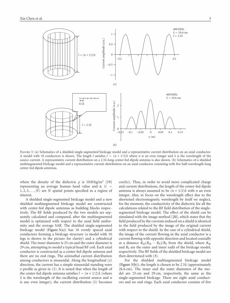
Figure 3: (a) Schematics of a shielded single-segmented birdcage model and a representative current distribution on an axial conductor.A model with 10 conductors is shown. The length l satisfies l = (n + 1/2)λ where n is an even integer and λ is the wavelength of thesource current. A representative current distribution on a 2.5λ-long center-fed dipole antenna is also shown. (b) Schematics of a shieldedmultisegmented birdcage model and a representative current distribution on an axial conductor consisting with five half-wavelength-longcenter-fed dipole antennas.
where the density of the dielectric ρ is 1030 kg/m3 [19]representing an average human head value and ri (i =1, 2, 3, . . . ,N) are N spatial points specified in a region ofinterest.
A shielded single-segmented birdcage model and a newshielded multisegmented birdcage model are constructedwith center-fed dipole antennas as building blocks respec-tively. The RF fields produced by the two models are sep-arately calculated and compared, after the multisegmentedmodel is optimized with respect to the axial field unifor-mity and the average SAR. The shielded single-segmentedbirdcage model (Figure 3(a)) has 16 evenly spaced axialconductors forming a birdcage structure (a model with 10legs is shown in the picture for clarity) and a cylindricalshield. The inner diameter is 25 cm and the outer diameter is29 cm, attempting to model a typical head RF coil. Each axialconductor is constructed as a center-fed dipole antenna andthere are no end rings. The azimuthal current distributionamong conductors is sinusoidal. Along the longitudinal (z)direction, the current has a simple sinusoidal standing wavez-profile as given in (1). It is noted that when the length ofthe center-fed dipole antenna satisfies l = (n + 1/2)λ (whereλ is the wavelength of the oscillating current source and nis any even integer), the current distribution (1) becomes
cos(kz). Thus, in order to avoid more complicated chargeand current distributions, the length of the center-fed dipoleantenna is always assumed to be (n + 1/2)λ with n an eveninteger. Also, to focus on the wavelength effect due to theshortened electromagnetic wavelength by itself we neglect,for the moment, the conductivity of the dielectric for all thecalculations related to the RF field distribution of the single-segmented birdcage model. The effect of the shield can besimulated with the image method [20], which states that thefield produced by the currents induced on a shield is identicalto the field produced by the image of the original currentwith respect to the shield. In the case of a cylindrical shield,the image of the current flowing in the axial conductor is acurrent flowing with opposite direction and located coaxiallyat a distance Rsh(Rsh − R0)/R0 from the shield, where Rsh
and R0 are the outer and inner radii of the birdcage model,respectively. The RF fields of the shielded birdcage model arethen determined with (3).
For the shielded multisegmented birdcage model(Figure 3(b)), the length is chosen to be 2.5λ (approximately26.6 cm). The inner and the outer diameters of the mo-del are 25 cm and 29 cm, respectively, the same as thesingle-segmented birdcage. There are eight axial conduct-ors and no end rings. Each axial conductor consists of five
4 International Journal of Antennas and Propagation
half-wavelength-long center-fed dipole antennas. Threeof them (the middle segment and the two on one side ofthe middle segment) are independently fed and the othertwo on the other side have current sources that are fixedby the axial symmetry around the central transverse plane.The image method described above is also applied here toincorporate the effect of the cylindrical shielding. Based on(3) and (6), the magnetic and the electric fields producedby each RF element (the half-wavelength-long center-feddipole antenna) can be calculated. Therefore, the magneticand the electric fields of the model are the superposition ofthe fields produced by all the individual RF elements andare functions of current amplitudes and phases on theseelements. In order to obtain a uniform RF field profile withcontrol over average SAR, a functional is constructed as
W= SAR
+Nr∑
j=1
λj
[B1,x
(I1,φ1, I2,φ2, . . . , IN0 ,φN0 ; r j
)− B(target)x
(r j)]
+Nr∑
j=1
μj
[B1,y
(I1,φ1, I2,φ2, . . . , IN0 ,φN0 ; r j
)− B(target)y
(r j)]
= 1NSAR
NSAR∑
i=1
σ
2ρ
∣∣E(
ri)∣∣2
+Nr∑
j=1
λj
[B1,x
(I1,φ1, I2,φ2, . . . , IN0 ,φN0 ; r j
)− B(target)x
(r j)]
+Nr∑
j=1
μj
[B1,y
(I1,φ1, I2,φ2, . . . , IN0 ,φN0 ; r j
)− B(target)y
(r j)].
(9)
Here, Ii and φi are the unknown current amplitude and phaseon the ith half-wavelength-long center-fed dipole antenna,N0 is the total number of the antennas (which is equal to 40in the present model), r j is the jth of the Nr total constraintpoints in the central axial plane where we calculate the xand y components of the RF field produced by the model(B1,x and B1,y) and impose the desired target field with both
uniform amplitude and phase (B(target)x = 0 and B
(target)y =
constant), and ri is the ith of the NSAR total spatial points in aregion of interest (ROI) where we determine the electric fieldE(ri) and the local SAR. A cylindrical ROI with a diameterof 16 cm and a length of 8 cm coaxially located within themultisegmented birdcage model, with their centers coincide,is selected for an illustrative SAR calculation. λj and μj
are the familiar Lagrange multipliers. The functional W isminimized to obtain a uniform RF field using a functionalapproach to control SAR. The minimization is achievedby differentiating with respect to Ii, φi, λj , and μj , andsolving the obtained 2N0 + 2Nr equations to find 2N0 + 2Nr
unknowns Ii, φi, λj , and μj . Since the SAR term is a quadraticfunction of unknown current amplitudes and phases, the2N0 + 2Nr equations are all linear and can be solved withmatrix inversion. Optimal current amplitudes and phasesare found and can be employed as sources parameters todetermine the corresponding RF field and SAR profiles.
3. RESULTS
The single-segmented birdcage model is assumed to bedriven by a current that is sinusoidal in the azimuthaldirection around any transverse plane
I j = I0ei(ωt+φj ), (10)
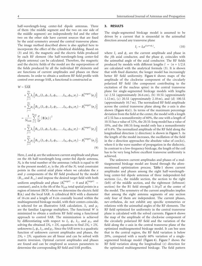
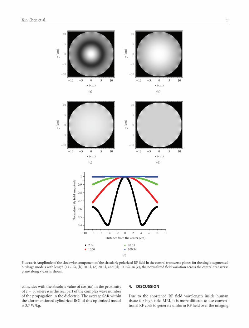
where I j and φj are the current amplitude and phase inthe jth axial conductor, and the phase φj coincides withthe azimuthal angle of the axial conductor. The RF fieldsproduced by models with different lengths l = (n + 1/2)λare calculated with the analytical formula (3). It is shownthat with fixed diameter, the longer model has increasinglybetter RF field uniformity. Figure 4 shows maps of theamplitude of the clockwise component of the circularlypolarized RF field (the component contributing to theexcitation of the nucleus spins) in the central transverseplane for single-segmented birdcage models with lengths(a) 2.5λ (approximately 26.6 cm), (b) 10.5λ (approximately1.12 m), (c) 20.5λ (approximately 2.18 m), and (d) 100.5λ(approximately 10.7 m). The normalized RF field amplitudeacross the central transverse plane along the x-axis is alsoshown (Figure 4(e)). In terms of the maximum percentagedeviation from the field at the center, the model with a lengthof 2.5λ has a nonuniformity of 60%, the one with a length of10.5λ has a value of 32%, the 20.5λ-long model has a value of10%, and the 100.5λ-long model only has a nonuniformityof 0.4%. The normalized amplitude of the RF field along thelongitudinal direction (z direction) is shown in Figure 5. Asthe length of the model increases, the oscillation of the fieldin the z direction approaches the absolute value of cos(kz),where k is the wave number of propagation in the dielectric.In contrast to a low-frequency birdcage, the length of the coilhas to be very long before excellent transverse uniformity isachieved.
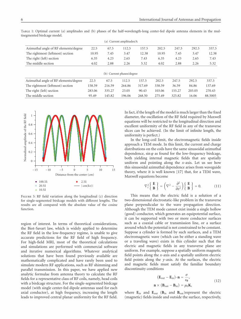
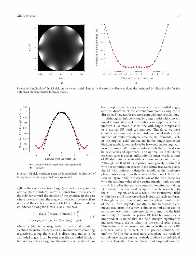
The unknown current amplitudes and phases of a mul-tisegmented birdcage model are found through the afore-mentioned optimization process. Table 1 shows currentamplitudes and phases among the eight half-wavelength-long center-fed dipole antennas of three independent-fedsections (i.e., the middle section, the section to the right(left) of the middle section, and the rightmost (leftmost)section) for the B1 field strength 1.16 μT at the center ofthe model. The symmetry of the current amplitudes impliesthat among the eight antenna segments of any sectiononly four of them are independent. The current phases,nev-ertheless, do not exhibit any specific symmetries orrelations with the azimuthal angles of the RF elements. TheRF field optimized for uniformity in the central transverseplane is calculated with the solved currents. Figure 6 showsthe map of the amplitude of the clockwise component ofthe circularly polarized RF field and the variation of thefield along the x-axis in the central transverse plane of theoptimized multisegmented birdcage model. It can bee seenthat in the central region, the RF field variation is below20%, compared with a nearly 60% variation of a single-segmented birdcage model (Figure 4). Figure 7 shows theRF field variation along the longitudinal (z) direction forthe optimized multisegmented birdcage. The field pattern
Xin Chen et al. 5
1050−5−10
x (cm)
−10
−5
0
5
10
y(c
m)
(a)
1050−5−10
x (cm)
−10
−5
0
5
10
y(c
m)
(b)
1050−5−10
x (cm)
−10
−5
0
5
10
y(c
m)
(c)
1050−5−10
x (cm)
−10
−5
0
5
10
y(c
m)
(d)
1086420−2−4−6−8−10
Distance from the center (cm)
0.4
0.5
0.6
0.7
0.8
0.9
1
Nor
mal
ized
B1
fiel
dam
plit
ude
2.5λ10.5λ
20.5λ100.5λ
(e)
Figure 4: Amplitude of the clockwise component of the circularly polarized RF field in the central transverse planes for the single-segmentedbirdcage models with length (a) 2.5λ, (b) 10.5λ, (c) 20.5λ, and (d) 100.5λ. In (e), the normalized field variation across the central transverseplane along x-axis is shown.
coincides with the absolute value of cos(αz) in the proximityof z = 0, where α is the real part of the complex wave numberof the propagation in the dielectric. The average SAR withinthe aforementioned cylindrical ROI of this optimized modelis 3.7 W/kg.
4. DISCUSSION
Due to the shortened RF field wavelength inside humantissue for high-field MRI, it is more difficult to use conven-tional RF coils to generate uniform RF field over the imaging
6 International Journal of Antennas and Propagation
Table 1: Optimal current (a) amplitudes and (b) phases of the half-wavelength-long center-fed dipole antenna elements in the mul-tisegmented birdcage model.
(a) Current amplitudes/A
Azimuthal angle of RF elements/degree 22.5 67.5 112.5 157.5 202.5 247.5 292.5 337.5
The rightmost (leftmost) section 10.95 7.45 3.47 12.38 10.95 7.45 3.47 12.38
The right (left) section 6.35 4.23 2.65 7.43 6.35 4.23 2.65 7.43
The middle section 4.02 2.88 2.26 5.32 4.02 2.88 2.26 5.32
(b) Current phases/degree
Azimuthal angle of RF elements/degree 22.5 67.5 112.5 157.5 202.5 247.5 292.5 337.5
The rightmost (leftmost) section 158.59 216.59 264.86 317.69 338.59 36.59 84.86 137.69
The right (left) section 283.06 335.27 23.05 90.43 103.06 155.27 203.05 270.43
The middle section 95.49 145.82 196.06 268.50 275.49 325.82 16.06 88.5005
151050−5−10−15
Distance from the center (cm)
0
0.2
0.4
0.6
0.8
1
Nor
mal
ized
ampl
itu
deof
the
RF
fiel
d
100.5λ20.5λ10.5λ
2.5λ| cos(kz)|
Figure 5: RF field variation along the longitudinal (z) directionfor single-segmented birdcage models with different lengths. Theresults are all compared with the absolute value of the cosinefunction.
region of interest. In terms of theoretical considerations,the Biot-Savart law, which is widely applied to determinethe RF field in the low-frequency regime, is unable to giveaccurate predictions for the RF field of high frequency.For high-field MRI, most of the theoretical calculationsand simulations are performed with commercial softwareand iterative numerical algorithms. Whatever analyticalsolutions that have been found previously available aremathematically complicated and have rarely been used tosimulate modern RF applications, such as RF shimming andparallel transmission. In this paper, we have applied newanalytic formulae from antenna theory to calculate the RFfields for a representative class of RF coils, namely, head coilswith a birdcage structure. For the single-segmented birdcagemodel (with single center-fed dipole antennas used for eachaxial conductor), at high frequency, increasing the lengthleads to improved central planar uniformity for the RF field.
In fact, if the length of the model is much larger than the fixeddiameter, the oscillation of the RF field required by Maxwellequations will be restricted to the longitudinal direction andexcellent uniformity of the RF field in any of the transverseslices can be achieved. (In the limit of infinite length, theuniformity is perfect.)
In the long-coil limit, the electromagnetic fields insideapproach a TEM mode. In this limit, the current and chargedistributions on the coils have the same sinusoidal azimuthaldependence, sinϕ as found for the low-frequency birdcage,both yielding internal magnetic fields that are spatiallyuniform and pointing along the x-axis. Let us see howthis sinusoidal azimuthal dependence arises from waveguidetheory, where it is well known [17] that, for a TEM wave,Maxwell equations become
∇2t
{EB
}=(∇2 − ∂2
∂z2
){EB
}= 0. (11)
This means that the electric field is a solution of atwo-dimensional electrostatic-like problem in the transverseplane perpendicular to the wave propagation direction.Although the TEM mode cannot exist inside a single hollow(good) conductor, which generates an equipotential surface,it can be supported with two or more conductor surfacessuch as a coaxial cable or transmission line, or a surfacearound which the potential is not constrained to be constant.Suppose a cylinder is formed by such surfaces, and a TEMelectromagnetic wave (which can be either a standing waveor a traveling wave) exists in this cylinder such that theelectric and magnetic fields in any transverse plane areuniform. For example, suppose a spatially uniform magneticfield points along the x-axis and a spatially uniform electricfield points along the y-axis. At the surfaces, the electricand magnetic fields must satisfy the familiar boundarydiscontinuity conditions
(Eout − Ein
)·n = σ
ε0,
n× (Bout − Bin) = μ0K,
(12)
where Ein and Eout (Bin and Bout)represent the electric(magnetic) fields inside and outside the surface, respectively,
Xin Chen et al. 7
1050−5−10
x (cm)
−10
−5
0
5
10
(a)
y(c
m)
6543210−1−2−3−4−5−6
Distance from the center (cm)
1
1.2
1.4
1.6
1.8
2
(b)
Nor
mal
ized
RF
fiel
dam
plit
ude
(a.u
.)
Figure 6: Amplitude of the RF field in the central axial plane (a) and across the diameter along the horizontal (x) direction (b) for theoptimized multisegmented birdcage model.
210−1−2
Distance from the center (cm)
0.65
0.7
0.75
0.8
0.85
0.9
0.95
1
1.05
Nor
mal
ized
RF
fiel
dam
plit
ude
(a.u
.)
Optimized multi-segmented birdcage model| cos(αz)|
Figure 7: RF field variation along the longitudinal (z) direction ofthe optimized multisegmented birdcage model.
σ(K) is the surface electric charge (current) density, and thenormal (to the surface) vector n points from the inside ofthe cylinder toward the outside of the cylinder. In the casewhere the electric and the magnetic fields outside the coil arezero, and the electric (magnetic) field is uniform inside thecylinder and along the y-axis (x-axis), we have
(0− E0ey
)·( cosϕex + sinϕey) = σ
ε0,
(cosϕex + sinϕey
)× (0− B0ex) = μ0K,
(13)
where E0 (B0) is the magnitude of the spatially uniformelectric (magnetic) field, ex and ey are unit vectors pointing,respectively, along the x and y directions, and ϕ is theazimuthal angle. It can be seen that the azimuthal distribu-tion of the electric charge and the surface current density are
both proportional to sinϕ where ϕ is the azimuthal angle,and the direction of the current flow points along the zdirection. These results are consistent with our calculations.
Although an infinitely long birdcage model with conven-tional sinusoidal current distribution can support a perfectlyuniform TEM mode, a short one with length comparableto a normal RF head coil can not. Therefore, we haveconstructed a multisegmented birdcage model with a largenumber of center-fed dipole antenna RF elements. Eachof the original axial conductors in the single-segmentedbirdcage model is now replaced by five equal subleg segmentsin our example. With our analytical tools the RF field canbe calculated and optimized. The optimal RF field showsexcellent central planar uniformity. In other words, a kindof RF shimming is achievable with our model and theory.Although excellent RF field planar homogeneity is achievedwith our optimization process in the central transverse plane,the RF field uniformity degrades rapidly as the transverseplane moves away from the center of the model. It can beseen in Figure 7 that the oscillation of the field coincideswith the absolute value of the cosine function only aroundz = 0. It implies that perfect sinusoidal longitudinal (alongz) oscillation of the field is approximately restricted tothe z = 0 region, and, as a result, the (transverse) fieldwithin the central transverse plane is approximately uniform.Although in the present solution the planar uniformityof the RF field degrades rapidly as the transverse planemoves away from the center, a similar optimization can beperformed over other transverse planes to improve the fielduniformity. Although the planar RF field homogeneity isimproved, it is noted that the field strength significantlyincreases toward the periphery of the central axial plane.This is due to large current amplitudes in the antenna RFelements (Table 1). In fact, in our present solution, theuniform field in the central transverse plane is a result ofpartial cancellations among the fields produced by individualantenna elements. Therefore, the current amplitudes on the
8 International Journal of Antennas and Propagation
54.543.532.521.51
Distance from the antenna (cm)
−0.5
0
0.5
1
1.5
2
2.5
3
3.5
4
Res
cale
dm
agn
itu
deof
the
com
plex
mag
net
icfi
eld
(a.u
.)
Analytical antenna formula, in the dielectric spaceNumerical simulation, in the dielectric spaceNumerical simulation, 1 cm gapNumerical simulation, 3 cm gap
σ = 0.59 S/m in all cases
(a)
54.543.532.521.51
Distance from the antenna (cm)
0
0.5
1
1.5
2
2.5
3
3.5
4
Res
cale
dco
mpl
exm
agn
etic
fiel
dam
plit
ude
(a.u
.)
Numerical simulations with 1 cm gap and σ = 0.59 S/mNumerical simulations with 3 cm gap and σ = 0.59 S/mAntenna formula without gap and σ = 3 S/m
(b)
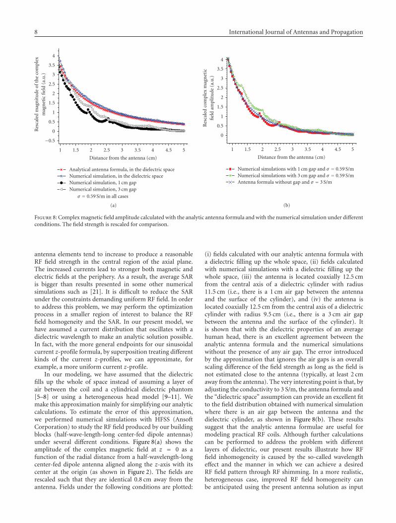
Figure 8: Complex magnetic field amplitude calculated with the analytic antenna formula and with the numerical simulation under differentconditions. The field strength is rescaled for comparison.
antenna elements tend to increase to produce a reasonableRF field strength in the central region of the axial plane.The increased currents lead to stronger both magnetic andelectric fields at the periphery. As a result, the average SARis bigger than results presented in some other numericalsimulations such as [21]. It is difficult to reduce the SARunder the constraints demanding uniform RF field. In orderto address this problem, we may perform the optimizationprocess in a smaller region of interest to balance the RFfield homogeneity and the SAR. In our present model, wehave assumed a current distribution that oscillates with adielectric wavelength to make an analytic solution possible.In fact, with the more general endpoints for our sinusoidalcurrent z-profile formula, by superposition treating differentkinds of the current z-profiles, we can approximate, forexample, a more uniform current z-profile.
In our modeling, we have assumed that the dielectricfills up the whole of space instead of assuming a layer ofair between the coil and a cylindrical dielectric phantom[5–8] or using a heterogeneous head model [9–11]. Wemake this approximation mainly for simplifying our analyticcalculations. To estimate the error of this approximation,we performed numerical simulations with HFSS (AnsoftCorporation) to study the RF field produced by our buildingblocks (half-wave-length-long center-fed dipole antennas)under several different conditions. Figure 8(a) shows theamplitude of the complex magnetic field at z = 0 as afunction of the radial distance from a half-wavelength-longcenter-fed dipole antenna aligned along the z-axis with itscenter at the origin (as shown in Figure 2). The fields arerescaled such that they are identical 0.8 cm away from theantenna. Fields under the following conditions are plotted:
(i) fields calculated with our analytic antenna formula witha dielectric filling up the whole space, (ii) fields calculatedwith numerical simulations with a dielectric filling up thewhole space, (iii) the antenna is located coaxially 12.5 cmfrom the central axis of a dielectric cylinder with radius11.5 cm (i.e., there is a 1 cm air gap between the antennaand the surface of the cylinder), and (iv) the antenna islocated coaxially 12.5 cm from the central axis of a dielectriccylinder with radius 9.5 cm (i.e., there is a 3 cm air gapbetween the antenna and the surface of the cylinder). Itis shown that with the dielectric properties of an averagehuman head, there is an excellent agreement between theanalytic antenna formula and the numerical simulationswithout the presence of any air gap. The error introducedby the approximation that ignores the air gaps is an overallscaling difference of the field strength as long as the field isnot estimated close to the antenna (typically, at least 2 cmaway from the antenna). The very interesting point is that, byadjusting the conductivity to 3 S/m, the antenna formula andthe “dielectric space” assumption can provide an excellent fitto the field distribution obtained with numerical simulationwhere there is an air gap between the antenna and thedielectric cylinder, as shown in Figure 8(b). These resultssuggest that the analytic antenna formulae are useful formodeling practical RF coils. Although further calculationscan be performed to address the problem with differentlayers of dielectric, our present results illustrate how RFfield inhomogeneity is caused by the so-called wavelengtheffect and the manner in which we can achieve a desiredRF field pattern through RF shimming. In a more realistic,heterogeneous case, improved RF field homogeneity canbe anticipated using the present antenna solution as input

Xin Chen et al. 9
followed by numerical algorithms in an iteration procedure,in order to converge to a better approximation.
Finally, the question arises about the construction ofan RF coil based on our model and theory. Althoughour present model has a total number of 40 antenna RFelements, these elements are not independent. First of all,the aforementioned symmetry with respect to the centralaxial plane of the multisegmented birdcage model reducesthe number of independent current sources from 5 × 8 =40 to 3 × 8 = 24. Furthermore, the current amplitudesfound with the optimization (as shown in Table 1) havecertain symmetry such that the current amplitude of oneantenna element is always identical to the current amplitudeof the antenna element diagonal to it. Although currentphases do not exhibit any specific symmetry, the optimalsolution may lead to further reduction of independentcurrent sources. While the purpose of the present workis to present a theoretical tool for an initial optimization,there are multiple solutions to the practical problems. Forexample, with respect to decoupling in transmit mode, wecould start with overlapping the nearest neighbor coils andthen add combinations of capacitive or inductive elementsfor the decoupling of the remaining (next nearest neighborand beyond) interactions. In particular, the present multi-segmented birdcage model, in any case, can be implementedas a “parallel transmit volume coil with independent controlof currents on the array elements” [22]. The techniquespresented in [22] can be applied to address the problems ofdecoupling and feeding for constructing a practical coil basedon the present model.
5. CONCLUSION
Due to the shortened wavelength of the RF field, RF fieldinhomogeneity has become a major challenge for high-fieldMRI. We present an analytic tool to simulate the RF fieldin the appropriate high-frequency limit. It is shown thatan analytic calculation based on antenna theory and anoptimization on that modeling can be effectively carried out.RF shimming is achievable to produce RF field with excellentplanar uniformity. Our model and analytical calculationscan help understand the relationship between the currentsources and the RF fields. The major advantage of the presentanalytic tools is efficiency; for instance, the calculations aremuch faster than numerical iterative algorithms (by orders ofmagnitude in comparisons with field calculations performedthrough numerical integrations). Important parameters suchas SAR can also be incorporated into the calculation andoptimization. We believe that the methods described herewill be quite useful in future RF coil designs.
ACKNOWLEDGMENTS
The authors are grateful to Shmaryu Shvartsman for helpfuldiscussions. They would like to thank Mark Griswold andJeremy Heilman for discussing practical coil designs basedon The authors model. This work is supported by the Stateof Ohio Third Frontier initiative.
REFERENCES
[1] J. T. Vaughan, M. Garwood, C. M. Collins, et al., “7T vs. 4T: RFpower, homogeneity, and signal-to-noise comparison in headimages,” Magnetic Resonance in Medicine, vol. 46, no. 1, pp.24–30, 2001.
[2] J. T. Vaughan, H. P. Hetherington, J. O. Otu, J. W. Pan, andG. M. Pohost, “High frequency volume coils for clinical NMRimaging and spectroscopy,” Magnetic Resonance in Medicine,vol. 32, no. 2, pp. 206–218, 1994.
[3] J. T. Vaughan, G. Adriany, C. J. Snyder, et al., “Efficient high-frequency body coil for high-field MRI,” Magnetic Resonancein Medicine, vol. 52, no. 4, pp. 851–859, 2004.
[4] J. Tropp, “Image brightening in samples of high dielectricconstant,” Journal of Magnetic Resonance, vol. 167, no. 1, pp.12–24, 2004.
[5] T. K. F. Foo, C. E. Hayes, and Y.-W. Kang, “Reduction of RFpenetration effects in high field imaging,” Magnetic Resonancein Medicine, vol. 23, no. 2, pp. 287–301, 1992.
[6] T. K. F. Foo, C. E. Hayes, and Y.-W. Kang, “An analyticalmodel for the design of RF resonators for MR body imaging,”Magnetic Resonance in Medicine, vol. 21, no. 2, pp. 165–177,1991.
[7] D. K. Spence and S. M. Wright, “2-D full wave solution forthe analysis and design of birdcage coils,” Concepts in MagneticResonance Part B, vol. 18B, no. 1, pp. 15–23, 2003.
[8] V. Taracila, L. S. Petropoulos, T. P. Eagan, and R. W. Brown,“Image uniformity improvement for birdcage-like volumecoils at 400 MHz using multichannel excitations,” Concepts inMagnetic Resonance Part B, vol. 29B, no. 3, pp. 153–160, 2006.
[9] T. S. Ibrahim, R. Lee, B. A. Baertlein, A. M. Abduljalil, H.Zhua, and P.-M. L. Robitaille, “Effect of RF coil excitation onfield inhomogeneity at ultra high fields: a field optimized TEMresonator,” Magnetic Resonance Imaging, vol. 19, no. 10, pp.1339–1347, 2001.
[10] F. Liu, B. L. Beck, J. R. Fitzsimmons, S. J. Blackband, andS. Crozier, “A theoretical comparison of two optimizationmethods for radiofrequency drive schemes in high frequencyMRI resonators,” Physics in Medicine and Biology, vol. 50, pp.5281–5291, 2005.
[11] W. Mao, M. B. Smith, and C. M. Collins, “Exploring thelimits of RF shimming for high-field MRI of the human head,”Magnetic Resonance in Medicine, vol. 56, no. 4, pp. 918–922,2006.
[12] P. Ullmann, S. Junge, M. Wick, F. Seifert, W. Ruhm, and J.Hennig, “Experimental analysis of parallel excitation usingdedicated coil setups and simultaneous RF transmission onmultiple channels,” Magnetic Resonance in Medicine, vol. 54,no. 4, pp. 994–1001, 2005.
[13] H. Fujita, L. S. Petropoulos, M. A. Morich, S. M. Shvartsmen,and R. W. Brown, “A hybrid inverse approach applied to thedesign of lumped-element RF coils,” IEEE Transactions onBiomedical Engineering, vol. 46, no. 3, pp. 353–361, 1999.
[14] H. Fujita, “New horizons in MR technology: RF coil designsand trends,” Magnetic Resonance in Medical Sciences, vol. 6,no. 1, pp. 29–42, 2007.
[15] C. M. Collins, W. Liu, J. Wang, et al., “Temperature and SARcalculations for a human head within volume and surface coilsat 64 and 300 MHz,” Journal of Magnetic Resonance Imaging,vol. 19, no. 5, pp. 650–656, 2004.
[16] Z. Wang, J. C. Lin, W. Mao, W. Liu, M. B. Smith, and C. M.Collins, “SAR and temperature: simulations and comparisonto regulatory limits for MRI,” Journal of Magnetic ResonanceImaging, vol. 26, no. 2, pp. 437–441, 2007.
10 International Journal of Antennas and Propagation
[17] J. D. Jackson, Classical Electrodynamics, John Wiley & Sons,New York, NY, USA, 3rd edition, 1999.
[18] C. A. Balanis, Antenna Theory: Analysis and Design, Harper &Row, New York, NY, USA, 1982.
[19] http://www.fcc.gov/cgi-bin/dielec.sh.[20] J. Jin, Electromagnetic Analysis and Design in Magnetic Reso-
nance Imaging, CRC Press, Boca Raton, Fla, USA, 1999.[21] C. Wang and G. X. Shen, “B1 field, SAR, and SNR comparisons
for birdcage, TEM, and microstrip coils at 7T,” Journal ofMagnetic Resonance Imaging, vol. 24, no. 2, pp. 439–443, 2006.
[22] K. N. Kurpad and S. M. Wright, “A parallel transmit volumecoil with independent control of currents on the arrayelements,” in Proceedings of the 13th International Society forMagnetic Resonance in Medicine (ISMRM ’05), p. 16, Miami,Fla, USA, May 2005.

International Journal of
AerospaceEngineeringHindawi Publishing Corporationhttp://www.hindawi.com Volume 2010
RoboticsJournal of
Hindawi Publishing Corporationhttp://www.hindawi.com Volume 2014
Hindawi Publishing Corporationhttp://www.hindawi.com Volume 2014
Active and Passive Electronic Components
Control Scienceand Engineering
Journal of
Hindawi Publishing Corporationhttp://www.hindawi.com Volume 2014
International Journal of
RotatingMachinery
Hindawi Publishing Corporationhttp://www.hindawi.com Volume 2014
Hindawi Publishing Corporation http://www.hindawi.com
Journal ofEngineeringVolume 2014
Submit your manuscripts athttp://www.hindawi.com
VLSI Design
Hindawi Publishing Corporationhttp://www.hindawi.com Volume 2014
Hindawi Publishing Corporationhttp://www.hindawi.com Volume 2014
Shock and Vibration
Hindawi Publishing Corporationhttp://www.hindawi.com Volume 2014
Civil EngineeringAdvances in
Acoustics and VibrationAdvances in
Hindawi Publishing Corporationhttp://www.hindawi.com Volume 2014
Hindawi Publishing Corporationhttp://www.hindawi.com Volume 2014
Electrical and Computer Engineering
Journal of
Advances inOptoElectronics
Hindawi Publishing Corporation http://www.hindawi.com
Volume 2014
The Scientific World JournalHindawi Publishing Corporation http://www.hindawi.com Volume 2014
SensorsJournal of
Hindawi Publishing Corporationhttp://www.hindawi.com Volume 2014
Modelling & Simulation in EngineeringHindawi Publishing Corporation http://www.hindawi.com Volume 2014
Hindawi Publishing Corporationhttp://www.hindawi.com Volume 2014
Chemical EngineeringInternational Journal of Antennas and
Propagation
International Journal of
Hindawi Publishing Corporationhttp://www.hindawi.com Volume 2014
Hindawi Publishing Corporationhttp://www.hindawi.com Volume 2014
Navigation and Observation
International Journal of
Hindawi Publishing Corporationhttp://www.hindawi.com Volume 2014
DistributedSensor Networks
International Journal of