Embed Size (px)
Citation preview
An Analytical Analysis of Fiber Waviness for
Laminated Curved Beam Under Bending
W. T. LU, Y. J. LIANG and E. V. IARVE
ABSTRACT
A closed-form analytical solution is developed for analyzing laminated
composite curved beam with fiber waviness. Explicit expressions for evaluating equivalent axial and bending stiffness are formulated based upon modified lamination theory and taking into consideration the structural deformation characteristics of beam with narrow section. The maximum radial stress is computed for a laminated composite curved beam with fiber waviness under four-point bending at any given location. The maximum radial stress results were in a good agreement with numerical results obtained by ABAQUS. It is concluded that the present approach is an efficient method for analyzing laminated composite curved beam with fiber waviness. INTRODUCTION
Fiber waviness is considered a common imperfection occurring in the manufacturing process of composite structures especially for thick composite laminates of compound curvature and in the region where the thickness is changing [1]. The imperfection is caused by non-uniform distribution of pressure and mismatch of thermal expansion (CTE) between tooling material, matrix, and fiber. This will cause longitudinal and transverse stresses in composite, including higher matrix contraction and fiber buckling as stated by Kantharaju [2]. Parameters on developing fiber waviness have been studied by Kugler and Moon [3]. They concluded that the influence of holding cure temperature is insignificant, but the cooling rate will affect the severity and the quantity of fiber waviness.
The concept of elastic moduli reduction for initial distortions of the reinforcing layers was first provided by Bolotin [4]. In his analysis, Kirchhoff hypothesis was used to describe the deformation of thin layers or slightly twisted plates with initial irregulations. In connection with the study of layered reinforced media with random initial irregularities, reduction on the modulus of elasticity in tension along the fibers of unidirectional glass-reinforced plastics (GRP) is proposed by Tarnopol'skii et al. _____________________________________________________________________________________________________
W.T. Lu, Y. J. Liang, and E. V. Iarve. Department of Mechanical and Aerospace
Engineering, University of Texas at Arlington, PO Box 19023, Arlington, TX 76019-
0023.
[5]. The shape of fiber irregularities is assumed to be a sinusoidal function. Bažant
[6] advanced their approach by taking into account changes in wave amplitude due
to radial forces. Three ideal cases of unidirectional fiber distributions were
discussed. The first one is parallel, uniformly distributed fibers with sinusoidal
curvature. The second one is not strictly parallel distributed fibers with sinusoidal
curvature. The third one is that fiber waves are equal in amplitude but in opposite
directions.
Extensive investigations of stiffness loss due to fiber waviness was
conducted in [7-9]. Lo and Chim [10] predicted the compressive strength of
unidirectional composite with fiber waviness. Adams and Hyer [11] experimentally
investigated multi-directional composite laminates under static compression loading.
They observed that severe waviness induced a static strength reduction of 36 %,
although the fiber waviness occurred in 0° ply and accounted for only 20 % of the
load carrying capacity of the laminate. Rai et al. [12] numerically investigated
lamina modulus as a function of fiber waviness, which is similar to [13-16]. They
concluded that fiber waviness, which occurs in 0° ply has significant influence on
stiffness reduction. If fiber waviness occurs in ±45° ply, the influence in stiffness
reduction is more pronounced in torsional cases than bending cases.
Fiber waviness can occur in either in-plane or out-of-plane for a laminated
beam [17]. The effects of out-of-plane fiber waviness for a lamina were further
investigated by Hsiao and Daniel [18-20]. Three types of fiber waviness are
considered including uniform, graded and localized fiber waviness. They concluded
that tensile and compressive elastic properties and nonlinear behavior in composite
materials can be significantly influenced by fiber waviness. Several researchers
applied numerical method for investigating effects of fiber waviness. Seon [21]
studied tape composite with fiber waviness by linear and nonlinear Finite Element
analysis (FE). The nonlinear interlaminar stress-strain relations can improve the
delamination inset prediction. He observed that the failure load for a rectangular
tape with small amplitude fiber waviness under tension is higher compared to fiber
waviness with large amplitude. Nikishkov et al. [22] conducted a numerical model
to investigate progressive fatigue damage in composites with fiber waviness.
However, most of analytical researches are not focused on out-plane fiber waviness
for a laminate composite beam. Therefore, the object of this research is to develop a
feasible and efficient approach to analyze composite curved beam with out-of-plane
fiber waviness.
CONSTITUTIVE EQUATIONS OF FIBER WAVINESS
Fiber waviness is a misalignment of the fibers in a ply. The presence of the
fiber waviness results in stiffness and strength loss and acts as a failure initiation in
composite structures. This section describes the extension of analytical methodology
for in-plane fiber waviness derived in [15] to application in composite curved beam
with out-of-plane fiber waviness.
Geometry of Fiber Waviness
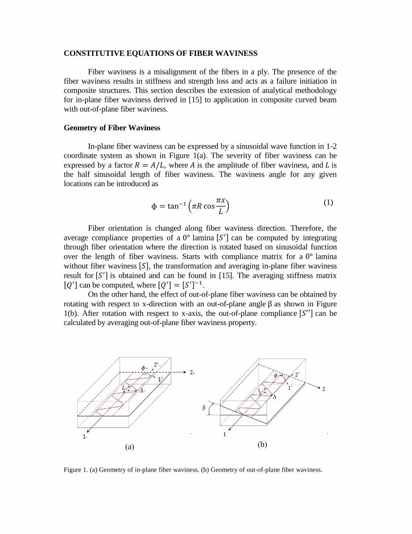
In-plane fiber waviness can be expressed by a sinusoidal wave function in 1-2
coordinate system as shown in Figure 1(a). The severity of fiber waviness can be
expressed by a factor 𝑅 = 𝐴/𝐿, where 𝐴 is the amplitude of fiber waviness, and 𝐿 is
the half sinusoidal length of fiber waviness. The waviness angle for any given
locations can be introduced as
ϕ = tan−1 (𝜋𝑅 cos𝜋𝑥
𝐿)
(1)
Fiber orientation is changed along fiber waviness direction. Therefore, the
average compliance properties of a 0° lamina [𝑆′] can be computed by integrating
through fiber orientation where the direction is rotated based on sinusoidal function
over the length of fiber waviness. Starts with compliance matrix for a 0° lamina
without fiber waviness [𝑆], the transformation and averaging in-plane fiber waviness
result for [𝑆′] is obtained and can be found in [15]. The averaging stiffness matrix
[𝑄′] can be computed, where [𝑄′] = [𝑆′]−1.
On the other hand, the effect of out-of-plane fiber waviness can be obtained by
rotating with respect to x-direction with an out-of-plane angle β as shown in Figure
1(b). After rotation with respect to x-axis, the out-of-plane compliance [𝑆′′] can be
calculated by averaging out-of-plane fiber waviness property.
Figure 1. (a) Geometry of in-plane fiber waviness. (b) Geometry of out-of-plane fiber waviness.
(b) (a)
[𝑆′′] = [𝑇𝜀(−𝛽)]𝑥[𝑆′][𝑇𝜎(𝛽)]𝑥 (2)
where
[𝑇𝜎(𝛽)]𝑥 =
[ 1 0 0 0 0 00 𝑚2 𝑛2 2𝑚𝑛 0 00 𝑛2 𝑚2 −2𝑚𝑛 0 00 −𝑚𝑛 𝑚𝑛 𝑚2 − 𝑛2 0 00 0 0 0 𝑚 −𝑛0 0 0 0 𝑛 𝑚 ]
[𝑇𝜀(𝛽)]𝑥 =
[ 1 0 0 0 0 00 𝑚2 𝑛2 𝑚𝑛 0 00 𝑚2 𝑛2 −𝑚𝑛 0 00 −2𝑚𝑛 2𝑚𝑛 𝑚2 − 𝑛2 0 00 0 0 0 𝑚 −𝑛0 0 0 0 𝑛 𝑚 ]
(3)
and 𝑚 = cos 𝛽 , 𝑛 = sin 𝛽. The averaged out-of-plane stiffness matrix [𝑄′′] =[𝑆′′]−1.
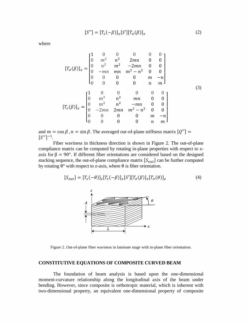
Fiber waviness in thickness direction is shown in Figure 2. The out-of-plane
compliance matrix can be computed by rotating in-plane properties with respect to x-
axis for β = 90°. If different fiber orientations are considered based on the designed
stacking sequence, the out-of-plane compliance matrix [𝑆𝑜𝑢𝑡] can be further computed
by rotating θ° with respect to z-axis, where θ is fiber orientation.
[𝑆𝑜𝑢𝑡] = [𝑇𝜀(−𝜃)]𝑧[𝑇𝜀(−𝛽)]𝑥[𝑆′][𝑇𝜎(𝛽)]𝑥[𝑇𝜎(𝜃)]𝑧 (4)
Figure 2. Out-of-plane fiber waviness in laminate stage with in-plane fiber orientation.
CONSTITUTIVE EQUATIONS OF COMPOSITE CURVED BEAM
The foundation of beam analysis is based upon the one-dimensional
moment-curvature relationship along the longitudinal axis of the beam under
bending. However, since composite is orthotropic material, which is inherent with
two-dimensional property, an equivalent one-dimensional property of composite

beam is needed. The equivalent one-dimensional property is dependent of the
structural response of the deformed beam and the structural response of the beam is
dependent on the ratio of the width to height of the beam cross-section. The
following section describes those behaviors.
Equivalent Stiffness for Composite Curved Beam
In order to satisfy behavior of thick curved beam, shear deformation and
rotary inertia are included in the derived equations. The force and moment
resultants are the integrals of the stresses over beam thickness. The equivalent
stiffness are the stiffness coefficients arising from the integration. More detail
derivation can be found in [23].
�̅�c = 𝑅𝑚 ∑[�̅�𝑥−𝑦]
𝑛
𝑘=1 kth
ln𝑅𝑚 + 𝑧𝑘
𝑅𝑚 + 𝑧𝑘−1
�̅�c = 𝑅𝑚 ∑[�̅�𝑥−𝑦]
𝑛
𝑘=1 kth
((𝑧𝑘 − 𝑧𝑘−1) − 𝑅𝑚 ln𝑅𝑚 + 𝑧𝑘
𝑅𝑚 + 𝑧𝑘−1)
�̅�c = 𝑅𝑚 ∑[�̅�𝑥−𝑦]
𝑛
𝑘=1 kth
(1
2(𝑧𝑘
2 − 𝑧𝑘−12 ) − 𝑅𝑚(𝑧𝑘 − 𝑧𝑘−1) + 𝑅𝑚
2 ln𝑅𝑚 + 𝑧𝑘
𝑅𝑚 + 𝑧𝑘−1)
𝐺𝐴 =5
4∑ 𝐺13 ((𝑧𝑘 − 𝑧𝑘−1) −
4
3𝑧𝑘2 (𝑧𝑘
3 − 𝑧𝑘−13 ))
𝑛
𝑘=1
(5)
where [�̅�𝑥−𝑦]𝑘𝑡ℎ
is stiffness matrix which takes fiber orientation into account at
kth ply, n is total ply number, 𝑅𝑚 is mean radius of the curved beam.
Beam with Narrow Section under Bending
If the width to height ratio of the cross-section is small (w/h < 6), the lateral
curvature is induced due to the effect of Poisson’s ratio. Hence, the response of
structure beam exhibits 𝑀𝑦 = 0 and Ky ≠ 0 for a narrow section beam.
With the above assumption, the constitutive equation for composite curved
beam with narrow cross-section can be written as one dimensional relationship
below:
[𝑁𝑥
𝑀𝑥] = [
𝐸𝐴 𝐸𝑉𝐸𝑉 𝐸𝐼
] [𝜀𝑥
0
𝑘𝑥] 𝑎𝑛𝑑 [
𝐸𝐴 𝐸𝑉𝐸𝑉 𝐸𝐼
] = [𝑎∗ 𝑏∗
𝑏∗ 𝑑∗]−1
(6)
where
𝑎∗ = 𝑎11 − 𝑏16
2
𝑑66 , 𝑏∗ = 𝑏11 −
𝑏16𝑑16
𝑑66 𝑎𝑛𝑑 𝑑∗ = 𝑑11 −
𝑑162
𝑑66 (7)
and
[𝑎 𝑏𝑏 𝑑
] = [�̅�c �̅�c
�̅�c �̅�c
]
−1
(8)
𝜀𝑥0 and x are the mid-plane strain and curvature along the longitudinal axis of the
beam, EA, EV, and EI refer to the equivalent axial, coupling and bending stiffness
and 𝑎∗,𝑏∗
and 𝑑∗ are the compliance, coupling and flexibility components of beam
laminate under bending, respectively. The matrices of a, b and d are the conventional
laminated plate properties.
CONSTITUTIVE EQUATION OF COMPOSITE CURVED BEAM WITH
FIBER WAVINESS
Equivalent Stiffness Properties with In-Plane Fiber Waviness
Configuration of curved lamina with in-plane fiber waviness is shown in
Figure 3(a). The average stiffness properties can be further obtained by replacing
[�̅�𝑥−𝑦]𝑘𝑡ℎ
to [𝑄′̅𝑥−𝑦]𝑘𝑡ℎ
using Eqs. (5), where [𝑄′̅𝑥−𝑦] is in-plane stiffness matrix
with fiber waviness property.
𝐴′̅c = 𝑅𝑚 ∑[𝑄′̅𝑥−𝑦]
𝑛
𝑘=1 kth
ln𝑅𝑚 + 𝑧𝑘
𝑅𝑚 + 𝑧𝑘−1
𝐵′̅c = 𝑅𝑚 ∑[𝑄′̅𝑥−𝑦]
𝑛
𝑘=1 kth
((𝑧𝑘 − 𝑧𝑘−1) − 𝑟 ln𝑅𝑚 + 𝑧𝑘
𝑅𝑚 + 𝑧𝑘−1)
𝐷′̅̅̅c = 𝑅𝑚 ∑[𝑄′̅𝑥−𝑦]
𝑛
𝑘=1 kth
(1
2(𝑧𝑘
2 − 𝑧𝑘−12 ) − 𝑅𝑚(𝑧𝑘 − 𝑧𝑘−1) + 𝑅𝑚
2 ln𝑅𝑚 + 𝑧𝑘
𝑅𝑚 + 𝑧𝑘−1)
(9)
Equivalent Stiffness Properties with Out-of-Plane Fiber Waviness
Out-of-plane fiber waviness will degrade the strength and fatigue performance
of composite structure. In general, non-uniform fiber waviness is observed along the
curved region instead of uniform fiber waviness. Therefore, a graded out-of-plane
fiber waviness is assumed, and its configuration is shown in Figure 3(b), where 𝐿𝐴𝑒𝑛𝑑𝑡𝑜𝑝
and 𝐿𝐴𝑒𝑛𝑑𝑏𝑜𝑡 are the location of plies where the zero amplitudes are observed on the
configuration. 𝐿𝐴𝑚𝑎𝑥 is the ply location where the maximum amplitude of fiber
waviness is observed.
Fiber waviness length, 𝐿, changes in the thickness direction where 𝐿𝑘𝑡ℎ and
𝑟𝑘𝑡ℎ are the length of fiber waviness and its corresponding radius for a lamina in kth
layer.
𝐿𝑘𝑡ℎ = 2𝜋𝑟𝑘𝑡ℎ (|𝜃𝑒𝑛𝑑 − 𝜃𝑠𝑡𝑎𝑟𝑡|
360) (10)

Figure 3. (a) In-plane fiber waviness in a curved lamina. (b) Out-of-plane fiber waviness in a curved
beam.
The amplitude of fiber waviness, Amax, is the maximum amplitude can be
observed. The amplitude below and above the location 𝐿𝐴𝑚𝑎𝑥 , where contains the
maximum amplitude are
𝐴𝑙𝑜𝑤 =𝐴𝑚𝑎𝑥(𝑝𝑙𝑦𝑙𝑜𝑤
𝑡ℎ − 𝐿𝐴𝑒𝑛𝑑𝑏𝑜𝑡 )
𝐿𝐴𝑚𝑎𝑥 − 𝐿𝐴𝑒𝑛𝑑𝑏𝑜𝑡
𝐴𝑢𝑝𝑝 =𝐴𝑚𝑎𝑥(𝑝𝑙𝑦𝑢𝑝𝑝
𝑡ℎ − 𝐿𝐴𝑚𝑎𝑥 + 1)
𝐿𝐴𝑒𝑛𝑑𝑡𝑜𝑝
− 𝐿𝐴𝑚𝑎𝑥
(11)
where 𝑝𝑙𝑦𝑙𝑜𝑤𝑡ℎ = 𝐿𝐴𝑒𝑛𝑑
𝑏𝑜𝑡 ~ 𝐿𝐴𝑚𝑎𝑥, and 𝑝𝑙𝑦𝑢𝑝𝑝𝑡ℎ = 𝐿𝐴𝑚𝑎𝑥 ~ 𝐿𝐴𝑒𝑛𝑑
𝑡𝑜𝑝− 1. Thus, the amplitude
can be displaced as 𝐴𝑚𝑝𝑙𝑖𝑡𝑢𝑑𝑒 = [𝐴𝑙𝑜𝑤 , 𝐴𝑢𝑝𝑝] from bottom ply to the top ply of entire
curved beam.
The equivalent stiffness property can be computed by replacing [𝑄′̅𝑥−𝑦]𝑘𝑡ℎ
to
[𝑄𝑜𝑢𝑡]𝑘𝑡ℎ, where [𝑄𝑜𝑢𝑡]𝑘𝑡ℎ = [𝑆𝑜𝑢𝑡]𝑘𝑡ℎ−1 .
𝐴′′̅̅̅̅c = 𝑅𝑚 ∑[𝑄𝑜𝑢𝑡]𝑘𝑡ℎ
𝑛
𝑘=1
ln𝑅𝑚 + 𝑧𝑘
𝑅𝑚 + 𝑧𝑘−1
𝐵′′̅̅̅̅c = 𝑅𝑚 ∑[𝑄𝑜𝑢𝑡]𝑘𝑡ℎ
𝑛
𝑘=1
((𝑧𝑘 − 𝑧𝑘−1) − 𝑅𝑚 ln𝑅𝑚 + 𝑧𝑘
𝑅𝑚 + 𝑧𝑘−1)
𝐷′′̅̅ ̅̅c = 𝑅𝑚 ∑[𝑄𝑜𝑢𝑡]𝑘𝑡ℎ
𝑛
𝑘=1
(1
2(𝑧𝑘
2 − 𝑧𝑘−12 ) − 𝑅𝑚(𝑧𝑘 − 𝑧𝑘−1) + 𝑅𝑚
2 ln𝑅𝑚 + 𝑧𝑘
𝑅𝑚 + 𝑧𝑘−1)
(12)
(a) (b)
Maximum Radial Stress Prediction
Lekhnitskii [24] provided closed-form methods for obtaining interlaminar
stress (through thickness stress) of a laminated curved beam under bending and
shearing load. Chung and Harold [25] provided a closed-form solution for a laminated
curved beam under axial load. By equating ∂σr
𝜕𝑟 to zero, the maximum delamination
stress along thickness direction σr𝑚𝑎𝑥 is obtained [26, 27]. Regarding Classical
Lamination Theory (CLT), no through thickness stress can be calculated because of
plane stress assumption.
Therefore, González [28] developed a method which takes interlaminar stresses, 𝜎𝑟
and 𝜏𝑟𝜃 into account based on CLT and equilibrium equations of the elasticity in
polar coordinates. The maximum radial stress for composite curved beam in this
section, is modified from [28, 29] and will be extended to apply for out-of-plane
fiber waviness in composite curved beam under bending.
σθ𝑖 (𝑟, 𝜃) =
𝑁𝑙𝑅𝑚(𝐸𝐴)𝑖
𝑤𝑡𝑟(𝑁(𝜃)
𝐸𝐴−
𝑀(𝜃)
𝐸𝑉+ (𝑟 − 𝑅) (
𝑀(𝜃)
𝐸𝐼−
𝑁(𝜃)
𝐸𝑉)) (13)
where 𝑁𝑙 is total ply number, Rm is mean radius of the curved beam, 𝐸𝐴, EV, and
EI are axial, coupling, and bending stiffness, respectively. 𝑁(𝜃) and 𝑀(𝜃) are axial
force and moment, respectively. 𝑤 is the width of the beam and 𝑡 is the thickness of
the complete beam. (𝐸𝐴)𝑖 is the equivalent axial stiffness to EA but in a ply only.
Once the circumferential stress has been obtained, the other stresses are obtained
due to equilibrium equations of the elasticity in polar coordinates.
𝜕𝜎𝜃
𝜕𝜃+
1
𝑟
𝜕(𝑟2𝜏𝑟𝜃)
𝜕𝑟= 0 ,
𝜕𝜎𝑟
𝜕𝑟+
𝜕𝜏𝑟𝜃
𝜕𝜃= 𝜎𝜃 (14)
Substituting Eqs. (13) to Eqs. (14), the radial stress 𝜎𝑟 due to applied moment is given
by
σ𝑟.𝑀𝑖 (𝑟, 𝜃) = 𝜎𝑟.𝑀
𝑖−1(𝑟𝑜𝑖 , 𝜃)𝑟𝑜𝑖
𝑟−
𝑁𝑙𝑅𝑚(𝐸𝐴)𝑖𝑀(𝜃)
𝑤𝑡𝑟𝐸𝐼 [𝑟𝑜𝑖 − 𝑟 − (𝑅𝑚 +
𝐸𝐼
𝐸𝑉) log
𝑟𝑜𝑖
𝑟] (15)
where σr.M0 = 0. However, Eqs. (15) is very sensitive with the given total ply number.
If the ply number is greater than 15 plies, the σr distribution is inaccurate compared to
closed-form solution provided by Lekhnitskii [24]. Therefore, a modified equation is
proposed to satisfy the specimen with large ply number.
σ𝑟.𝑀𝑖 (𝑟, 𝜃) = σr,M
i−1 (𝑟𝑖𝑟𝑜
) +𝑅𝑚𝑄(1,1)𝑀(𝜃)
𝑟𝐸𝐼[𝑟𝑜 − 𝑟𝑖 − (𝑅𝑚 +
𝐸𝐼
𝐸𝑉) log
𝑟𝑜𝑟𝑖
] (16)
where 𝑟𝑖 is the inner radius of the ply, 𝑟𝑜 is the outer radius of the ply, 𝑄(1,1) is the
stiffness component along θ direction for a given ply.
In order to satisfy equivalent stiffness in composite curved beam with fiber
waviness, in Eqs. (17), 𝑄(1,1) can be replaced to [𝑄(1,1)𝑜𝑢𝑡]𝑘𝑡ℎ. It should be noted that
constant ply thickness is assumed in Eqs. (16). However, if fiber waviness is presented, ply
thickness is going to be functional of the amplitude of fiber waviness in each ply. Therefore,
Eqs (16) can be modified as
σ𝑟.𝑀𝑖 (𝑟, 𝜃) = σr,M
i−1 (𝑟𝑖𝑖𝑟𝑜𝑜
) +𝑅𝑚[𝑄(1,1)𝑜𝑢𝑡]𝑘𝑡ℎ𝑀(𝜃)
𝑟𝐸𝐼[𝑟𝑜𝑜 − 𝑟𝑖𝑖 − (𝑅𝑚 +
𝐸𝐼
𝐸𝑉) log
𝑟𝑜𝑜
𝑟𝑖𝑖] (17)
where 𝑟𝑖𝑖 = 𝑟𝑖 + 𝐴𝑚𝑝𝑙𝑖𝑡𝑢𝑑𝑒𝑖 and 𝑟𝑜𝑜 = 𝑟𝑜 + 𝐴𝑚𝑝𝑙𝑖𝑡𝑢𝑑𝑒𝑖. 𝐴𝑚𝑝𝑙𝑖𝑡𝑢𝑑𝑒𝑖 is the amplitude
of fiber waviness in ith ply.
FINITE ELEMENT ANALYSIS
Mesh, Element Used and Model Validation
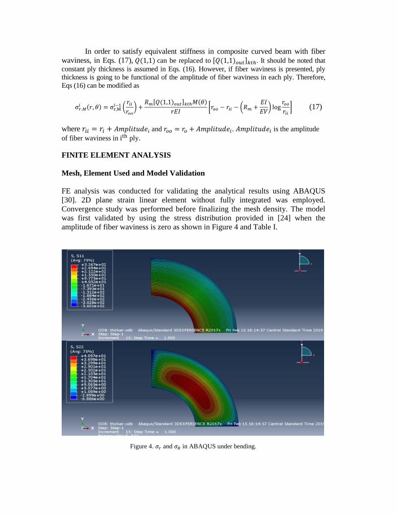
FE analysis was conducted for validating the analytical results using ABAQUS
[30]. 2D plane strain linear element without fully integrated was employed.
Convergence study was performed before finalizing the mesh density. The model
was first validated by using the stress distribution provided in [24] when the
amplitude of fiber waviness is zero as shown in Figure 4 and Table I.
Figure 4. 𝜎𝑟 and 𝜎𝜃 in ABAQUS under bending.
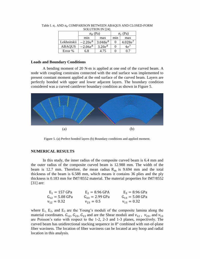
Table I. 𝜎𝑟 AND 𝜎𝜃 COMPARISON BETWEEN ABAQUS AND CLOSED-FORM
SOLUTION IN [24].
𝜎𝜃 (Pa) 𝜎𝑟 (Pa)
min max min max
Lekhnitskii −2.20𝑒8 3.048𝑒8 0 4.028𝑒7
ABAQUS −2.06𝑒8 3.20𝑒8 0 4𝑒7
Error % 6.8 4.75 0 0.7
Loads and Boundary Conditions
A bending moment of 20 N-m is applied at one end of the curved beam. A
node with coupling constrains connected with the end surface was implemented to
present constant moment applied at the end surface of the curved beam. Layers are
perfectly bonded with upper and lower adjacent layers. The boundary condition
considered was a curved cantilever boundary condition as shown in Figure 5.
Figure 5. (a) Perfect bonded layers (b) Boundary conditions and applied moment.
NUMERICAL RESULTS
In this study, the inner radius of the composite curved beam is 6.4 mm and
the outer radius of the composite curved beam is 12.988 mm. The width of the
beam is 12.7 mm. Therefore, the mean radius Rm is 9.694 mm and the total
thickness of the beam is 6.588 mm, which means it contains 36 plies and the ply
thickness is 0.183 mm for IM7/8552 material. The material properties for IM7/8552
[31] are:
E1 = 157 GPa E2 = 8.96 GPA E3 = 8.96 GPa
G12 = 5.08 GPa G23 = 2.99 GPa G13 = 5.08 GPa
v12 = 0.32 v23 = 0.5 v13 = 0.32
where E1, E2, and E3 are the Young’s moduli of the composite lamina along the
material coordinates. 𝐺12, 𝐺23, 𝐺13 and are the Shear moduli and 𝜈12 , 𝜈23, and 𝜈13
are Poisson’s ratio with respect to the 1-2, 2-3 and 1-3 planes, respectively. The
curved beam has unidirectional stacking sequence in 0° combined with out-of-plane
fiber waviness. The location of fiber waviness can be located at any hoop and radial
location in this analysis.
(a) (b)
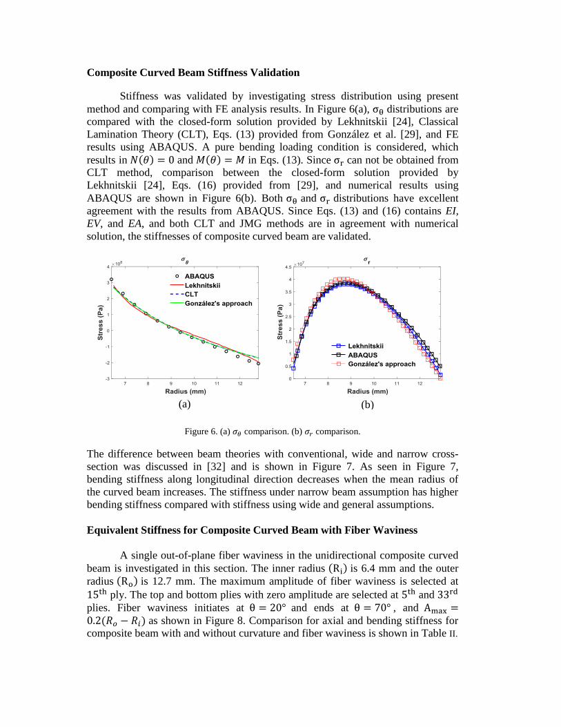
Composite Curved Beam Stiffness Validation
Stiffness was validated by investigating stress distribution using present
method and comparing with FE analysis results. In Figure 6(a), σθ distributions are
compared with the closed-form solution provided by Lekhnitskii [24], Classical
Lamination Theory (CLT), Eqs. (13) provided from González et al. [29], and FE
results using ABAQUS. A pure bending loading condition is considered, which
results in 𝑁(𝜃) = 0 and 𝑀(𝜃) = 𝑀 in Eqs. (13). Since σr can not be obtained from
CLT method, comparison between the closed-form solution provided by
Lekhnitskii [24], Eqs. (16) provided from [29], and numerical results using
ABAQUS are shown in Figure 6(b). Both σθ and σr distributions have excellent
agreement with the results from ABAQUS. Since Eqs. (13) and (16) contains EI,
EV, and EA, and both CLT and JMG methods are in agreement with numerical
solution, the stiffnesses of composite curved beam are validated.
Figure 6. (a) 𝜎𝜃 comparison. (b) 𝜎𝑟 comparison.
The difference between beam theories with conventional, wide and narrow cross-
section was discussed in [32] and is shown in Figure 7. As seen in Figure 7,
bending stiffness along longitudinal direction decreases when the mean radius of
the curved beam increases. The stiffness under narrow beam assumption has higher
bending stiffness compared with stiffness using wide and general assumptions.
Equivalent Stiffness for Composite Curved Beam with Fiber Waviness
A single out-of-plane fiber waviness in the unidirectional composite curved
beam is investigated in this section. The inner radius (Ri) is 6.4 mm and the outer
radius (Ro) is 12.7 mm. The maximum amplitude of fiber waviness is selected at
15th ply. The top and bottom plies with zero amplitude are selected at 5th and 33rd
plies. Fiber waviness initiates at θ = 20° and ends at θ = 70° , and Amax =0.2(𝑅𝑜 − 𝑅𝑖) as shown in Figure 8. Comparison for axial and bending stiffness for
composite beam with and without curvature and fiber waviness is shown in Table II.
(a) (b)
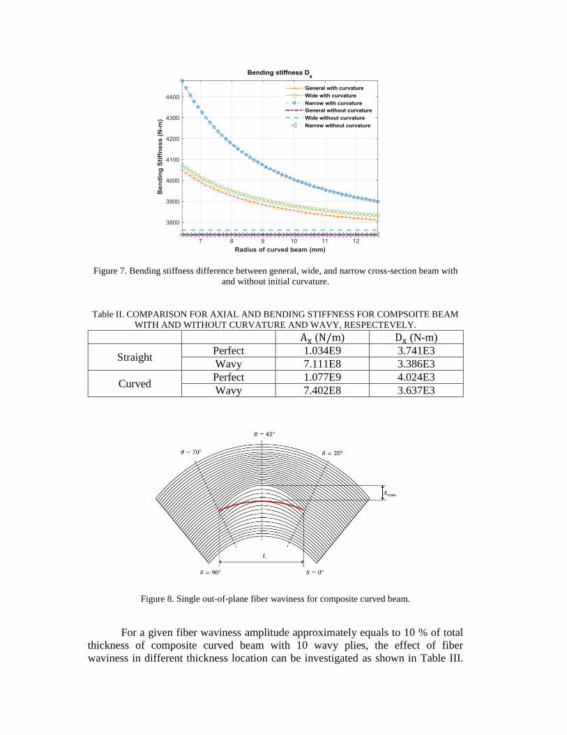
Figure 7. Bending stiffness difference between general, wide, and narrow cross-section beam with
and without initial curvature.
Table II. COMPARISON FOR AXIAL AND BENDING STIFFNESS FOR COMPSOITE BEAM
WITH AND WITHOUT CURVATURE AND WAVY, RESPECTEVELY.
Ax (N/m) Dx (N-m)
Straight Perfect 1.034E9 3.741E3
Wavy 7.111E8 3.386E3
Curved Perfect 1.077E9 4.024E3
Wavy 7.402E8 3.637E3
Figure 8. Single out-of-plane fiber waviness for composite curved beam.
For a given fiber waviness amplitude approximately equals to 10 % of total
thickness of composite curved beam with 10 wavy plies, the effect of fiber
waviness in different thickness location can be investigated as shown in Table III.
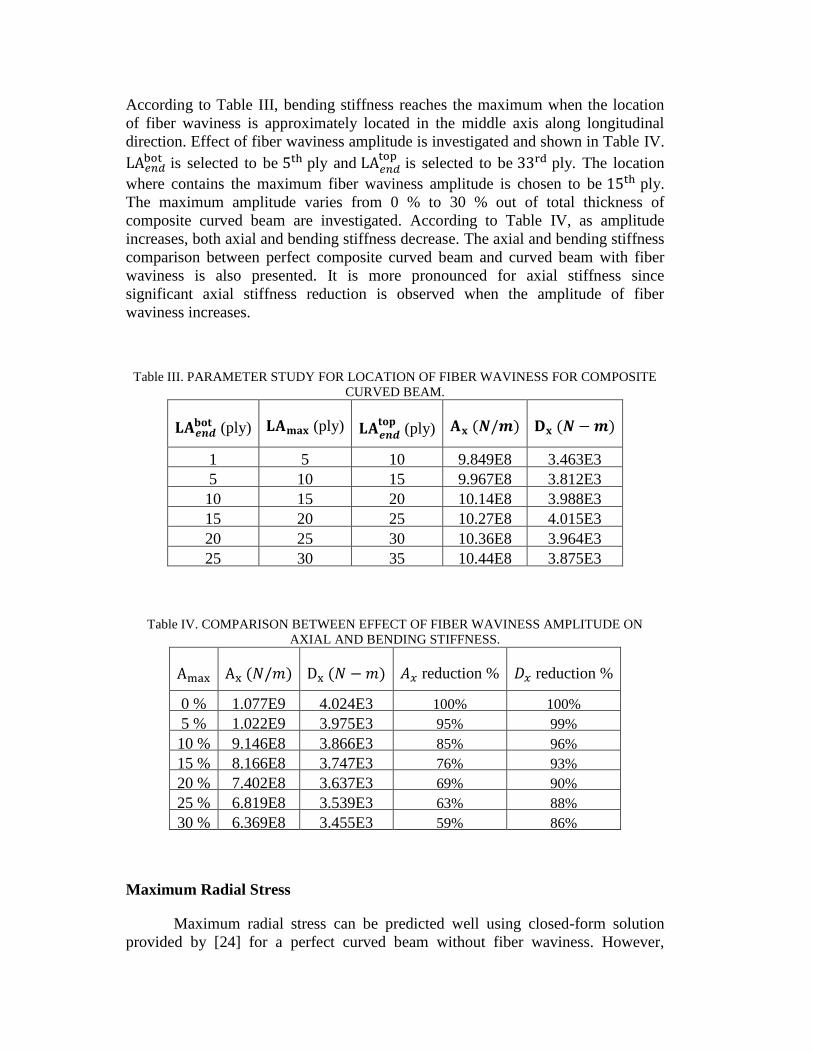
According to Table III, bending stiffness reaches the maximum when the location
of fiber waviness is approximately located in the middle axis along longitudinal
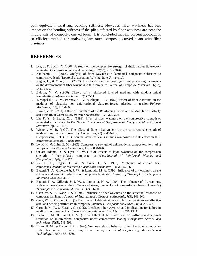
direction. Effect of fiber waviness amplitude is investigated and shown in Table IV.
LA𝑒𝑛𝑑bot is selected to be 5th ply and LA𝑒𝑛𝑑
top is selected to be 33rd ply. The location
where contains the maximum fiber waviness amplitude is chosen to be 15th ply.
The maximum amplitude varies from 0 % to 30 % out of total thickness of
composite curved beam are investigated. According to Table IV, as amplitude
increases, both axial and bending stiffness decrease. The axial and bending stiffness
comparison between perfect composite curved beam and curved beam with fiber
waviness is also presented. It is more pronounced for axial stiffness since
significant axial stiffness reduction is observed when the amplitude of fiber
waviness increases.
Table III. PARAMETER STUDY FOR LOCATION OF FIBER WAVINESS FOR COMPOSITE
CURVED BEAM.
𝐋𝐀𝒆𝒏𝒅𝐛𝐨𝐭 (ply) 𝐋𝐀𝐦𝐚𝐱 (ply) 𝐋𝐀𝒆𝒏𝒅
𝐭𝐨𝐩 (ply) 𝐀𝐱 (𝑵/𝒎) 𝐃𝐱 (𝑵 − 𝒎)
1 5 10 9.849E8 3.463E3
5 10 15 9.967E8 3.812E3
10 15 20 10.14E8 3.988E3
15 20 25 10.27E8 4.015E3
20 25 30 10.36E8 3.964E3
25 30 35 10.44E8 3.875E3
Table IV. COMPARISON BETWEEN EFFECT OF FIBER WAVINESS AMPLITUDE ON
AXIAL AND BENDING STIFFNESS.
Amax Ax (𝑁/𝑚) Dx (𝑁 − 𝑚) 𝐴𝑥 reduction % 𝐷𝑥 reduction %
0 % 1.077E9 4.024E3 100% 100%
5 % 1.022E9 3.975E3 95% 99%
10 % 9.146E8 3.866E3 85% 96%
15 % 8.166E8 3.747E3 76% 93%
20 % 7.402E8 3.637E3 69% 90%
25 % 6.819E8 3.539E3 63% 88%
30 % 6.369E8 3.455E3 59% 86%
Maximum Radial Stress
Maximum radial stress can be predicted well using closed-form solution
provided by [24] for a perfect curved beam without fiber waviness. However,

maximum radial stress will be relocated and varied if fiber waviness is introduced.
The σr comparison between present method using Eqs. (17) and FE results with and
without fiber waviness is shown in Figure 9. The σr distribution has excellent
agreement with FE results. The maximum σr predicted from present method is
48.00 MPa and maximum σr obtained from FE analysis is 49.85 MPa. The error
percentage is less than 4 % between the result from present method and FE analysis.
Moreover, the location which has maximum σr using present method is r = 10.27
mm, and the location which has maximum σr using FE analysis is r = 10.26 mm.
The error percentage is less than 1 % between the result from present method and
FE analysis.
Figure 9. 𝜎𝑟 Comparison between present and FE results with and without fiber waviness.
CONCLUDING REMARKS
A closed-form analytical solution is developed for analyzing laminated
composite curved beam with presence fiber waviness. The explicit expressions for
evaluating equivalent axial and bending stiffness are formulated based upon
modified lamination theory and taking into consideration the structural deformation
characteristics of beam with narrow section. The maximum radial stress is
computed for a laminated composite curved beam with fiber waviness under four-
point bending at any random location. The present stiffness and stress results are in
good agreement with numerical results from ABAQUS. It is found that the
geometry of fiber waviness such as location and amplitude have great impact on
both equivalent axial and bending stiffness. However, fiber waviness has less
impact on the bending stiffness if the plies affected by fiber waviness are near the
middle axis of composite curved beam. It is concluded that the present approach is
an efficient method for analyzing laminated composite curved beam with fiber
waviness.
REFERENCES
1. Lee, J., & Soutis, C. (2007) A study on the compressive strength of thick carbon fibre-epoxy
laminates. Composite science and technology, 67(10), 2015-2026.
2. Kantharaju, H. (2012). Analysis of fiber waviness in laminated composite subjected to
compressive loads (Doctoral dissertation, Wichita State University).
3. Kugler, D., & Moon, T. J. (2002). Identification of the most significant processing parameters
on the development of fiber waviness in thin laminates. Journal of Composite Materials, 36(12),
1451-1479.
4. Bolotin, V. V. (1966). Theory of a reinforced layered medium with random initial
irregularities. Polymer mechanics, 2(1), 7-11.
5. Tarnopol'skii, Y. M., Portnov, G. G., & Zhigun, I. G. (1967). Effect of fiber curvature on the
modulus of elasticity for unidirectional glass-reinforced plastics in tension. Polymer
Mechanics, 3(2), 161-166.
6. Bažant, Z. P. (1968). Effect of Curvature of the Reinforcing Fibers on the Moduli of Elasticity
and Strength of Composites. Polymer Mechanics, 4(2), 251-258.
7. Lin, K. Y., & Zhang, X. J. (1992). Effect of fiber waviness on the compressive strength of
laminated composites. In The Second International Symposium on Composite Materials and
Structures(pp. 120-125).
8. Wisnom, M. R. (1990). The effect of fibre misalignment on the compressive strength of
unidirectional carbon fibre/epoxy. Composites, 21(5), 403-407.
9. Camponeschi, E. T. (1991). Lamina waviness levels in thick composites and its effect on their
compression strength. Composites.
10. Lo, K. H., & Chim, E. M. (1992). Compressive strength of unidirectional composites. Journal of
Reinforced Plastics and Composites, 11(8), 838-896.
11. O'Hare Adams, D., & Hyer, M. W. (1993). Effects of layer waviness on the compression
strength of thermoplastic composite laminates. Journal of Reinforced Plastics and
Composites, 12(4), 414-429.
12. Rai, H. G., Rogers, C. W., & Crane, D. A. (1992). Mechanics of curved fiber
composites. Journal of reinforced plastics and composites, 11(5), 552-566.
13. Bogetti, T. A., Gillespie Jr, J. W., & Lamontia, M. A. (1992). Influence of ply waviness on the
stiffness and strength reduction on composite laminates. Journal of Thermoplastic Composite
Materials, 5(4), 344-369.
14. Bogetti, T. A., Gillespie Jr, J. W., & Lamontia, M. A. (1994). The influence of ply waviness
with nonlinear shear on the stiffness and strength reduction of composite laminates. Journal of
Thermoplastic Composite Materials, 7(2), 76-90.
15. Chan, W. S., & Wang, J. S. (1994). Influence of fiber waviness on the structural response of
composite laminates. Journal of Thermoplastic Composite Materials, 7(3), 243-260.
16. Chan, W. S., & Chou, C. J. (1995). Effects of delamination and ply fiber waviness on effective
axial and bending stiffnesses in composite laminates. Composite structures, 30(3), 299-306.
17. Garnich, M. R., & Karami, G. (2005). Localized fiber waviness and implications for failure in
unidirectional composites. Journal of composite materials, 39(14), 1225-1245.
18. Hsiao, H. M., & Daniel, I. M. (1996). Effect of fiber waviness on stiffness and strength
reduction of unidirectional composites under compressive loading. Composites science and
technology, 56(5), 581-593.
19. Hsiao, H. M., & Daniel, I. M. (1996). Nonlinear elastic behavior of unidirectional composites
with fiber waviness under compressive loading. Journal of Engineering Materials and
Technology, 118(4), 561-570.
20. Hsiao, H. M., & Daniel, I. M. (1996). Elastic properties of composites with fiber
waviness. Composites Part A: Applied Science and Manufacturing, 27(10), 931-941.
21. Seon, G. (2009). Finite element-based failure models for carbon/epoxy tape
composites (Doctoral dissertation, Georgia Institute of Technology).
22. Nikishkov, Y., Makeev, A., & Seon, G. (2013). Progressive fatigue damage simulation method
for composites. International Journal of Fatigue, 48, 266-279.
23. Qatu, M. S. (1993). Theories and analyses of thin and moderately thick laminated composite
curved beams. International Journal of Solids and Structures, 30(20), 2743-2756.
24. Lekhnitskii, S. G. (1968). Anisotropic plates (No. FTD-HT-23-608-67). Foreign Technology
Div Wright-Patterson Afb Oh.
25. Cheung, C. K., & Sorensen, H. C. (2007). Effect of axial loads on radial stress in curved
beams. Wood and Fiber Science, 15(3), 263-275.
26. Tolf, G. (1983). Stresses in a curved laminated beam. Fibre Science and Technology, 19(4),
243-267.
27. Ko, W. L. (1988). Delamination stresses in semicircular laminated composite bars.
28. González Cantero, J.M. (2017). Study of the unfolding failure of curved composite laminates..
(Tesis Doctoral Inédita). Universidad de Sevilla, Sevilla.
29. González-Cantero, J. M., Graciani, E., Blázquez, A., & París, F. (2014, June). Analytic
evaluation of radial stresses in unfolding failure of composite materials. Comparison with
numerical solutions. In Proceedings of the 16th European Conference on Composite Materials
ECCM16 (pp. 22-26).
30. Abaqus/Standard, V6.14-2, is a trademark of ABAQUS, Inc.
31. Makeev, A., Seon, G., Nikishkov, Y., Nguyen, D., Mathews, P., & Robeson, M. (2019).
Analysis Methods for Improving Confidence in Material Qualification for Laminated
Composites. Journal of the American Helicopter Society, 64(1), 1-13.
32. Lu, W., Singh, S., & Chan, W. (2019). A novel stress analysis method for composite Z-
stiffeners under mechanical and thermal loads. Journal of Composite Materials.