Embed Size (px)
Citation preview
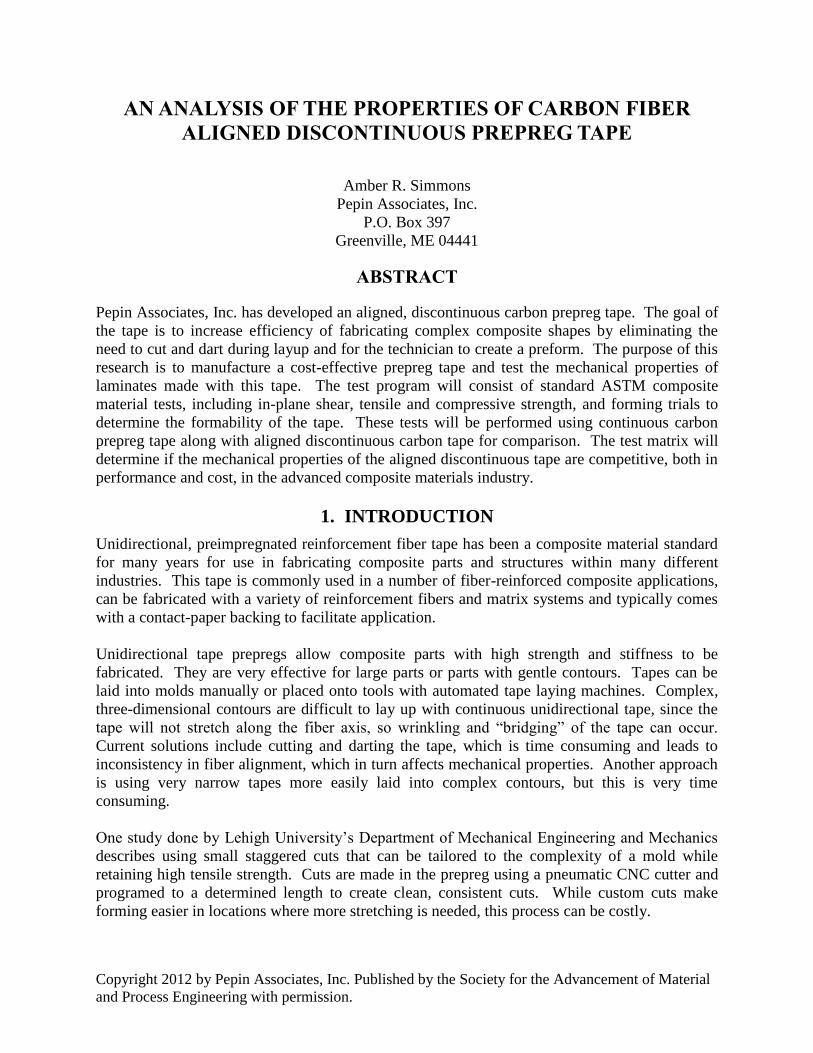
Copyright 2012 by Pepin Associates, Inc. Published by the Society for the Advancement of Material
and Process Engineering with permission.
AN ANALYSIS OF THE PROPERTIES OF CARBON FIBER
ALIGNED DISCONTINUOUS PREPREG TAPE
Amber R. Simmons
Pepin Associates, Inc.
P.O. Box 397
Greenville, ME 04441
ABSTRACT
Pepin Associates, Inc. has developed an aligned, discontinuous carbon prepreg tape. The goal of
the tape is to increase efficiency of fabricating complex composite shapes by eliminating the
need to cut and dart during layup and for the technician to create a preform. The purpose of this
research is to manufacture a cost-effective prepreg tape and test the mechanical properties of
laminates made with this tape. The test program will consist of standard ASTM composite
material tests, including in-plane shear, tensile and compressive strength, and forming trials to
determine the formability of the tape. These tests will be performed using continuous carbon
prepreg tape along with aligned discontinuous carbon tape for comparison. The test matrix will
determine if the mechanical properties of the aligned discontinuous tape are competitive, both in
performance and cost, in the advanced composite materials industry.
1. INTRODUCTION
Unidirectional, preimpregnated reinforcement fiber tape has been a composite material standard
for many years for use in fabricating composite parts and structures within many different
industries. This tape is commonly used in a number of fiber-reinforced composite applications,
can be fabricated with a variety of reinforcement fibers and matrix systems and typically comes
with a contact-paper backing to facilitate application.
Unidirectional tape prepregs allow composite parts with high strength and stiffness to be
fabricated. They are very effective for large parts or parts with gentle contours. Tapes can be
laid into molds manually or placed onto tools with automated tape laying machines. Complex,
three-dimensional contours are difficult to lay up with continuous unidirectional tape, since the
tape will not stretch along the fiber axis, so wrinkling and “bridging” of the tape can occur.
Current solutions include cutting and darting the tape, which is time consuming and leads to
inconsistency in fiber alignment, which in turn affects mechanical properties. Another approach
is using very narrow tapes more easily laid into complex contours, but this is very time
consuming.
One study done by Lehigh University’s Department of Mechanical Engineering and Mechanics
describes using small staggered cuts that can be tailored to the complexity of a mold while
retaining high tensile strength. Cuts are made in the prepreg using a pneumatic CNC cutter and
programed to a determined length to create clean, consistent cuts. While custom cuts make
forming easier in locations where more stretching is needed, this process can be costly.
Pepin Associates, Inc. has developed a means by which continuous, unidirectional prepreg tape
is cut into narrow, discrete segments while maintaining alignment and adherence to its contact
paper backing. The result is an aligned, discontinuous unidirectional tape. The discontinuous
nature of the tape allows it to stretch in its reinforcement direction, permitting the forming of
complex shaped layups from simple initial shapes such as flat plates and tubes.
The prepreg tape is processed by means of a specialized machine, which cuts the tape into
discrete segments using a rotary die. The die is geared to and turns against an anvil, and can be
designed to cut the segments in lengths tailored to a specific application. The pattern of the cuts
can also be varied. The segment length is a compromise between two competing interests. The
first is the formability of the prepreg tape into the required contour. The tape stretching occurs
when the fiber segments slip relative to one another. The force required to stretch the tape is a
function of the segment length and segment width. The second is the retention of mechanical
properties of the discontinuous composite compared to the baseline continuous fiber composite.
Generally the longer fiber segments have better properties. The equipment used to fabricate the
aligned, discontinuous unidirectional tape permit varying the segment length and other
architecture features to tailor the prepreg for specific part design and manufacturing process.
Discontinuous, unidirectional preimpregnated reinforcement tape begins with standard
preimpregnated unidirectional reinforcement tape of any fiber type and any matrix system. The
standard unidirectional tape is processed in a machine designed to cut the continuous fibers of
the unidirectional tape into discrete segments. The patterns of these segments are governed by
the required mechanical properties of the part and the contours to be formed. One typical design
would be a brick-like pattern, with rows having their junctions midway between the junctions of
the segments in the adjacent row. This pattern would allow tape stretching while still retaining
shear contact from one segment to its adjacent or neighboring segment.
The machine uses a set of initial nip rollers to gather the continuous unidirectional tape as it
feeds from an adjacent spool and separates the plastic separation layer typically used during
fabrication. The separation layer is then passed over the die on a hemispherical guide plate and
rejoined with the tape at a final set of nip rollers after it passes through the die and anvil. The
processed tape is taken up on a constant tension textile spool winder, modified to wind tape. An
articulated final single roller called a dancer arm is mechanically linked to a mechanism on the
winder, which modulates the winder speed to ensure a constant tension on the tape.
The rotary die and anvil can be manually operated with a hand wheel, or an electric clutch can
engage a motor drive to advance the unidirectional prepreg tape between the rotary die and anvil.
The die cuts the prepreg tape as it is pressed against the anvil. The die is referred to as a “flex
die,” which is etched onto a thin substrate and adheres to a magnetic roller. This type of die
facilitates pattern changes and replacement.
The die design makes only crosscuts in the unidirectional tape, taking advantage of the natural
tendency of the filaments to slide axially relative to each other due to their attachment only by a
matrix. This method avoids the problems of segments adhering to the die cavities and being
pulled from their backing as the tape is cut. The resulting crosscuts are overlapped to ensure that
all filaments are cut, and to account for lateral drift in axial filaments.
2. EXPERIMENTATION
The purpose of this study is to understand the behavior of the aligned discontinuous prepreg tape.
Initially, forming trials were conducted to determine which flex die pattern offers the best
formability results with the prepreg. Once the pattern is selected, coupons are cut from cured
panels and tested following ASTM Composite Standards. Testing includes tensile, compression,
in-plane shear and interlaminar shear testing. The flex die pattern chosen for this study is a
straight cut design with segments spaced 1.65 cm apart.
2.1 Materials
Hexcel® HexPly® IM7-G/8552 with resin content 35.2% was used to prepare eight panels: four
control continuous panels and four aligned discontinuous panels.
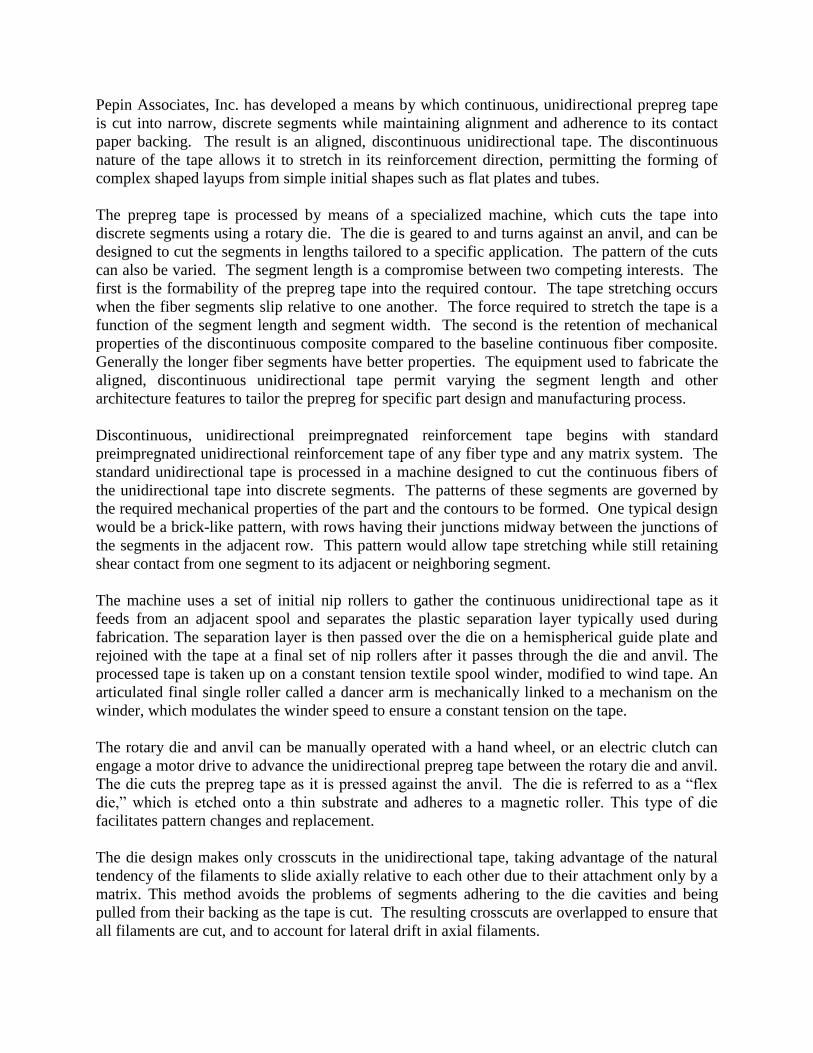
Laminates measuring 33 cm x 33 cm were fabricated by PAI. Laminate thickness for each panel
follows the ASTM requirements for each test. All panels were cured following the Hexcel®
8552 resin system shown in Figure 1.
Figure 1. Graph of recorded data during one of two autoclave runs. The IM7/8552 cure cycle is
approximately 6 hours. Temperature inside the autoclave (red), temperature seen by the panels
(blue), and vacuum pressure (green) are recorded during the run.
2.2 Dome Forming
The scope of work done for the forming trials will determine the workability of the aligned
discontinuous prepreg over a male hemisphere. Once a flex die pattern has been tested and
provides satisfying forming results, pattern will be used to fabricate panels for mechanical
property testing.
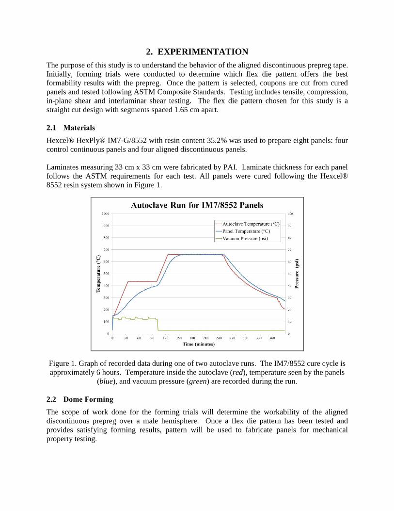
The test set up shown in Figure 2 consists of a 40.6 cm x 45.7 cm double diaphragm forming
frame with the prepreg forming around a hard 10.2 cm male hemisphere tool. The forming
frame consists of two silicone sheets forming a flat vacuum bag above the chamber while the
hard hemisphere tool is positioned in the bottom chamber of the frame.
Figure 2. Double diaphragm forming frame layers. The two top silicone sheets make up the flat
vacuum bag where the prepreg layups are positioned in the center. The hard hemisphere tool is
seen in the bottom chamber.
2.2.1 Procedure
The prepreg blank size is placed in the top vacuum bag between two sheets of HTF621 Teflon
release film. A breather strip is placed between the Teflon sheets and prepreg to evacuate air
trapped between the layers. Once the air is evacuated from the top silicone vacuum bag, two
heat pads are placed on the double diaphragm frame; one on top of the silicone vacuum bag and
one inside the bottom chamber touching the bottom silicone sheet of the vacuum bag. The heat
pads are heated to 109˚C. A thermocouple is used to accurately measure the temperature above
the top silicone layer. Once the desired temperature is reached and held for 5 minutes, the
bottom chamber is evacuated at full vacuum and the prepreg inside the vacuum bag forms over
the tool. The preform may be removed once the forming frame has cooled between room
temperature and 30˚C.
2.3 Mechanical Testing Procedures
2.3.1 Load and Strain Recording
In order to record strain readings during each test, strain gauge amplifiers are connected to a
digital image correlation software developed by Correlated Solutions. Strain gauges are wired to
the amplifiers which are connected to the program. This set up is also used to record the load
applied during each test. Two load cells will be used during each test; one connected to the
digital image correlation software, and the other connected to the test machine to control the load
cycle for each test. Load and strain data is collected at a rate of 4 readings per second and saved
to the computer in the form of a spreadsheet.
2.3.2 ASTM Composite Standards
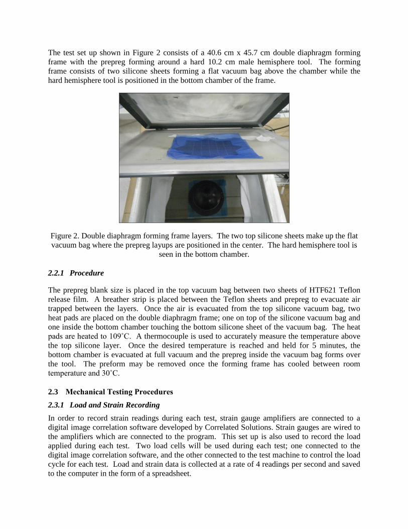
Table 1 lists the ASTM Composite Standards that Pepin Associates, Inc. used to perform the
tests. These tests will be used to define the mechanical properties of the laminates prepared with
the aligned, discontinuous unidirectional prepreg tape. Coupon layups shown in the table are
chosen based on the ASTM minimum thickness requirements for each test.
Table 1. ASTM Coupon Test Matrix
ASTM
Standard Test Type
Coupon
Layup
Coupon
Width
(mm)
Coupon
Length
(mm)
Crosshead
Speed
(mm/minute)
No. of
Replicates
D2344 Interlaminar
Shear [0]42 25.4 38 1.3 5
D3039 Tensile [0]8 13.0 254 3.2 3
D3410 Compression [0]14 13.0 114 1.3 5
D3518 In-Plane
Shear [±45]5s 25.4 254 3.2 5
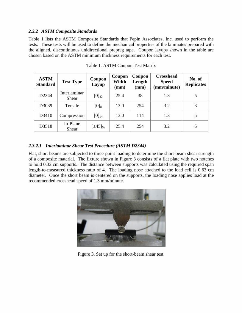
2.3.2.1 Interlaminar Shear Test Procedure (ASTM D2344)
Flat, short beams are subjected to three-point loading to determine the short-beam shear strength
of a composite material. The fixture shown in Figure 3 consists of a flat plate with two notches
to hold 0.32 cm supports. The distance between supports was calculated using the required span
length-to-measured thickness ratio of 4. The loading nose attached to the load cell is 0.63 cm
diameter. Once the short beam is centered on the supports, the loading nose applies load at the
recommended crosshead speed of 1.3 mm/minute.
Figure 3. Set up for the short-beam shear test.
2.3.2.2 Tensile Test Procedure (ASTM D3039)
Coupons are gripped at both ends with the bottom grip fixed. The top grip will pull the coupon
at a set crosshead speed shown for each test in Table 1 above. Glass tabs are bonded to the
gripped ends of each coupon to prevent gripping damage during testing. The crosshead speed
was chosen based on testing development and initial trials. Slower crosshead rates caused the
coupons to slip between the grips. Load applied and axial strain at three points during each test
will be recorded.
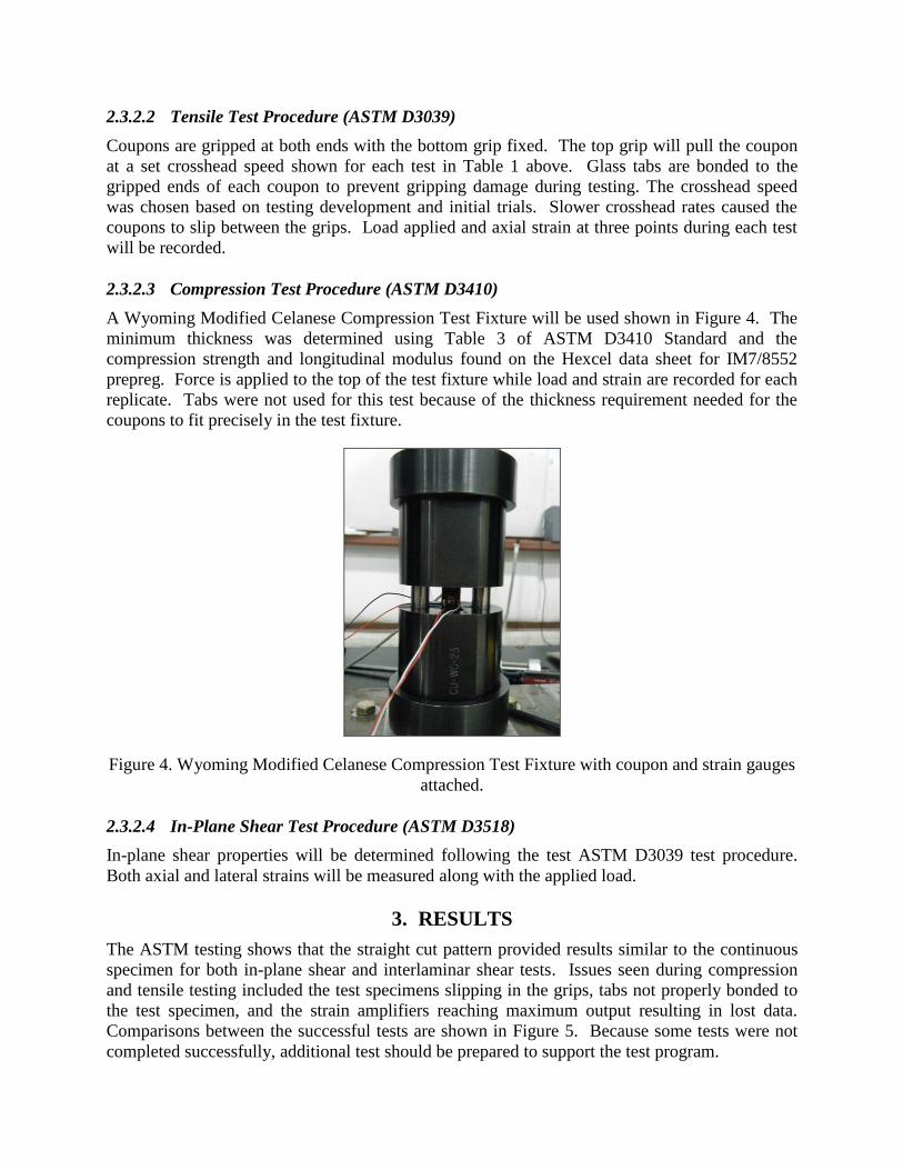
2.3.2.3 Compression Test Procedure (ASTM D3410)
A Wyoming Modified Celanese Compression Test Fixture will be used shown in Figure 4. The
minimum thickness was determined using Table 3 of ASTM D3410 Standard and the
compression strength and longitudinal modulus found on the Hexcel data sheet for IM7/8552
prepreg. Force is applied to the top of the test fixture while load and strain are recorded for each
replicate. Tabs were not used for this test because of the thickness requirement needed for the
coupons to fit precisely in the test fixture.
Figure 4. Wyoming Modified Celanese Compression Test Fixture with coupon and strain gauges
attached.
2.3.2.4 In-Plane Shear Test Procedure (ASTM D3518)
In-plane shear properties will be determined following the test ASTM D3039 test procedure.
Both axial and lateral strains will be measured along with the applied load.
3. RESULTS
The ASTM testing shows that the straight cut pattern provided results similar to the continuous
specimen for both in-plane shear and interlaminar shear tests. Issues seen during compression
and tensile testing included the test specimens slipping in the grips, tabs not properly bonded to
the test specimen, and the strain amplifiers reaching maximum output resulting in lost data.
Comparisons between the successful tests are shown in Figure 5. Because some tests were not
completed successfully, additional test should be prepared to support the test program.
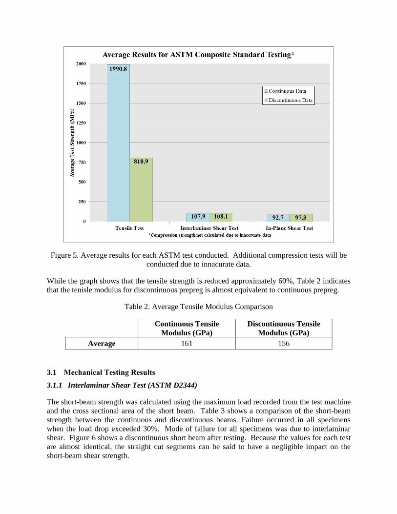
Figure 5. Average results for each ASTM test conducted. Additional compression tests will be
conducted due to innacurate data.
While the graph shows that the tensile strength is reduced approximately 60%, Table 2 indicates
that the tenisle modulus for discontinuous prepreg is almost equivalent to continuous prepreg.
Table 2. Average Tensile Modulus Comparison
Continuous Tensile
Modulus (GPa)
Discontinuous Tensile
Modulus (GPa)
Average 161 156
3.1 Mechanical Testing Results
3.1.1 Interlaminar Shear Test (ASTM D2344)
The short-beam strength was calculated using the maximum load recorded from the test machine
and the cross sectional area of the short beam. Table 3 shows a comparison of the short-beam
strength between the continuous and discontinuous beams. Failure occurred in all specimens
when the load drop exceeded 30%. Mode of failure for all specimens was due to interlaminar
shear. Figure 6 shows a discontinuous short beam after testing. Because the values for each test
are almost identical, the straight cut segments can be said to have a negligible impact on the
short-beam shear strength.
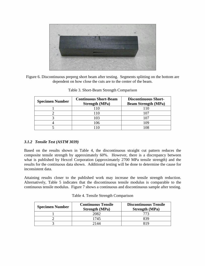
Figure 6. Discontinuous prepreg short beam after testing. Segments splitting on the bottom are
dependent on how close the cuts are to the center of the beam.
Table 3. Short-Beam Strength Comparison
Specimen Number Continuous Short-Beam
Strength (MPa)
Discontinuous Short-
Beam Strength (MPa)
1 110 110
2 110 107
3 103 107
4 106 109
5 110 108
3.1.2 Tensile Test (ASTM 3039)
Based on the results shown in Table 4, the discontinuous straight cut pattern reduces the
composite tensile strength by approximately 60%. However, there is a discrepancy between
what is published by Hexcel Corporation (approximately 2700 MPa tensile strength) and the
results for the continuous data shown. Additional testing will be done to determine the cause for
inconsistent data.
Attaining results closer to the published work may increase the tensile strength reduction.
Alternatively, Table 5 indicates that the discontinuous tensile modulus is comparable to the
continuous tensile modulus. Figure 7 shows a continuous and discontinuous sample after testing.
Table 4. Tensile Strength Comparison
Specimen Number Continuous Tensile
Strength (MPa)
Discontinuous Tensile
Strength (MPa)
1 2082 773
2 1745 839
3 2144 819
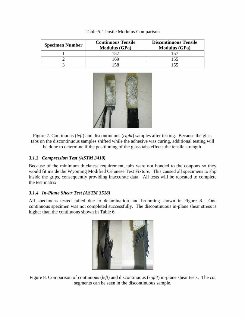
Table 5. Tensile Modulus Comparison
Specimen Number Continuous Tensile
Modulus (GPa)
Discontinuous Tensile
Modulus (GPa)
1 157 157
2 169 155
3 158 155
Figure 7. Continuous (left) and discontinuous (right) samples after testing. Because the glass
tabs on the discontinuous samples shifted while the adhesive was curing, additional testing will
be done to determine if the positioning of the glass tabs effects the tensile strength.
3.1.3 Compression Test (ASTM 3410)
Because of the minimum thickness requirement, tabs were not bonded to the coupons so they
would fit inside the Wyoming Modified Celanese Test Fixture. This caused all specimens to slip
inside the grips, consequently providing inaccurate data. All tests will be repeated to complete
the test matrix.
3.1.4 In-Plane Shear Test (ASTM 3518)
All specimens tested failed due to delamination and brooming shown in Figure 8. One
continuous specimen was not completed successfully. The discontinuous in-plane shear stress is
higher than the continuous shown in Table 6.
Figure 8. Comparison of continuous (left) and discontinuous (right) in-plane shear tests. The cut
segments can be seen in the discontinuous sample.
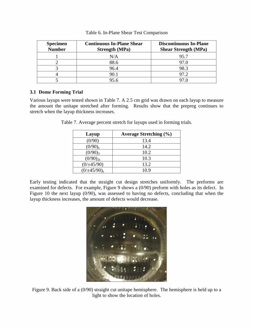
Table 6. In-Plane Shear Test Comparison
Specimen
Number
Continuous In-Plane Shear
Strength (MPa)
Discontinuous In-Plane
Shear Strength (MPa)
1 N/A 95.7
2 88.6 97.0
3 96.4 98.3
4 90.1 97.2
5 95.6 97.0
3.1 Dome Forming Trial
Various layups were tested shown in Table 7. A 2.5 cm grid was drawn on each layup to measure
the amount the unitape stretched after forming. Results show that the prepreg continues to
stretch when the layup thickness increases.
Table 7. Average percent stretch for layups used in forming trials.
Layup Average Stretching (%)
(0/90) 13.4
(0/90)s 14.2
(0/90)3 10.2
(0/90)2s 10.3
(0/±45/90) 13.2
(0/±45/90)s 10.9
Early testing indicated that the straight cut design stretches uniformly. The preforms are
examined for defects. For example, Figure 9 shows a (0/90) preform with holes as its defect. In
Figure 10 the next layup (0/90)s was assessed to having no defects, concluding that when the
layup thickness increases, the amount of defects would decrease.
Figure 9. Back side of a (0/90) straight cut unitape hemisphere. The hemisphere is held up to a
light to show the location of holes.
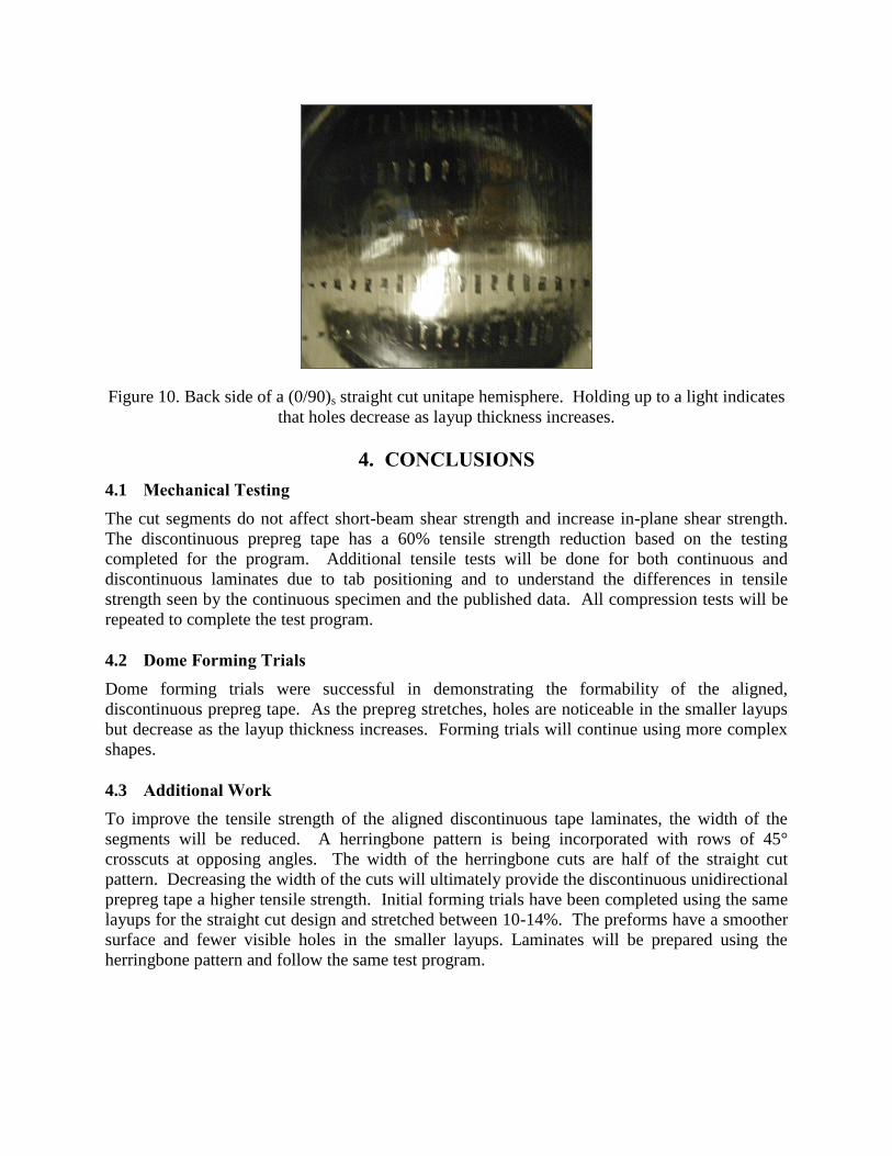
Figure 10. Back side of a (0/90)s straight cut unitape hemisphere. Holding up to a light indicates
that holes decrease as layup thickness increases.
4. CONCLUSIONS
4.1 Mechanical Testing
The cut segments do not affect short-beam shear strength and increase in-plane shear strength.
The discontinuous prepreg tape has a 60% tensile strength reduction based on the testing
completed for the program. Additional tensile tests will be done for both continuous and
discontinuous laminates due to tab positioning and to understand the differences in tensile
strength seen by the continuous specimen and the published data. All compression tests will be
repeated to complete the test program.
4.2 Dome Forming Trials
Dome forming trials were successful in demonstrating the formability of the aligned,
discontinuous prepreg tape. As the prepreg stretches, holes are noticeable in the smaller layups
but decrease as the layup thickness increases. Forming trials will continue using more complex
shapes.
4.3 Additional Work
To improve the tensile strength of the aligned discontinuous tape laminates, the width of the
segments will be reduced. A herringbone pattern is being incorporated with rows of 45°
crosscuts at opposing angles. The width of the herringbone cuts are half of the straight cut
pattern. Decreasing the width of the cuts will ultimately provide the discontinuous unidirectional
prepreg tape a higher tensile strength. Initial forming trials have been completed using the same
layups for the straight cut design and stretched between 10-14%. The preforms have a smoother
surface and fewer visible holes in the smaller layups. Laminates will be prepared using the
herringbone pattern and follow the same test program.
5. ACKNOWLEDGEMENTS
Pepin Associates, Inc. would like to thank the Office of Naval Research for funding the work
described in this paper. We would also like to thank Dr. Guenther Jacobsen at Hexcel
Corporation for helping us attain the material used for this study.
6. REFERENCES
1. ASTM Standard D2344/D2344M-00, 2006, “Standard Test Method for Short-Beam Strength
of Polymer Matrix Composite Materials and Their Laminates” ASTM International, West
Conshohocken, PA, 2006, DOI:10.1520/D2334_D2334M-00R06, www.astm.org.
2. ASTM Standard D3039/D3039M-08, 2008, “Standard Test Method for Tensile Properties of
Polymer Matrix Composite Materials” ASTM International, West Conshohocken, PA, 2007,
DOI:10.1520/D3039_D3039M-08, www.astm.org.
3. ATSM Standard D3410/D3410M-03, 2003, “Standard Test Method for Compressive
Properties of Polymer Matrix Composite Materials with Unsupported Gage Section by Shear
Loading” ASTM International, West Conshohocken, PA, 2003,
DOI:10.1520/D3410_D3410M-03R08, www.astm.org.
4. ASTM Standard D3518/D3518M-94, 2007, “Standard Test Method for IN-Plane Shear
Response of Polymer Matrix Composite Materials by Tensile test of a ±45˚ Laminate”
ASTM International, West Conshohocken, PA, 2001, DOI:10.1520/D3518_D3518M-94R07,
www.astm.org. [Insert reference 4]
5. Grenestedt, Joachim. “Stretchable Unidirectional Fiber Reinforcement.” Final Report under
U.S. Army Research Office Contract Number W911NF-08.
6. “HexPly® 8552 Epoxy Matrix Product Data.”
http://hexcel.com/Resources/DataSheets/Prepreg-Data-Sheets/8552_us.pdf. December 2007.
Hexcel Corporation, Stamford, CT, USA.