Embed Size (px)
Citation preview
An Analysis of the Developments in Blended Wing BodyAircraft for Sustainable Aviation
Shilpa Isabella D’souza (1000534709)*
University of Toronto Institute for Aerospace Studies
Conventional air transport vehicles have over the years damaged our planet to a large extent. This ledto the concept of making aircraft more environmental friendly. To achieve this, a great deal of research anddevelopment went into various methods that could reduce air and noise pollution caused by aircraft. The firstand most obvious approach in this regard was to increase the fuel efficiency. Gradually, different designs andconfigurations were suggested. One of the most successful designs in this category is the Blended Wing Body.The wings of an aircraft of this design are blended with the fuselage to form an integrated structure. The bodyof a blended wind body aircraft is usually flattened and airfoil shaped. This maximizes the lift to drag ratio,improving the overall fuel efficiency of the aircraft. Blended wing body aircraft also produce less noise andcan have a larger payload capacity with respect to the size of the aircraft. The main aim of this report is tocover the formulation, design, and recent studies and developments in Blended Wing Body aircraft and theirfeasibility.
Nomenclature
ACFA Active Control for flexible aircraftACT Active Control TechnologyANOPP Aircraft Noise Prediction ProgramBWB Blended Wing BodyCFD Computational Fluid DynamicsDEE Design and Engineering EngineFMMG Flight Mechanics Model GeneratorLFC Laminar Flow ControlPAA Propulsion Airframe AeroacousticsWingMOD Wing Multidisciplinary Optimization Design
I. Introduction
The design of aircraft has rapidly changed over the past several decades. Not only has there been a marked im-provement in the structural configuration of the aircraft, but there has also a signification improvement in performance.With this increasing performance, the negative impact on the environment has been worsening due to an increase inthe total anthropogenic carbon dioxide emissions. Aviation contributes around 2% of the total anthropogenic carbondioxide emissions. However, carbon dioxide emissions alone are misleading as they do not represent the total radiativeforcing from aviation, which is in fact closer to 5%1. It is estimated that there will be an exponential growth in airtravel over the coming years and a proportional increase in the negative environmental impact. This includes noise andpollution due to emissions. The conventional aircraft design needed improvement to meet the growing sustainabilityneeds. This led to the design and development of alternate aircraft configurations. The blended wing body (BWB)aircraft is not a fully novel concept because it was considered by Horten, Northrop, and others from the mid 1930s tothe mid 1950s, but was abandoned due to stability and control problems. The primary research in this area has beencarried out by NASA Langley Research Center and McDonnell Douglas. The design they produced evolved over theyears and is now known in literature as the BWB configuration2.
As the name suggests, the fuselage of a BWB acts as a wing as well as a pitch control surface and it does not havea tail. With this simple modification, the aircraft reduces interference drag to a great degree. This is due to the smoothjunction between the wing and the fuselage. The fuselage also plays an important role in the generation of lift byreducing the wing loading. This provides benefits in terms of aerodynamic performance3. A BWB design approachis to maximize the overall efficiency by improving the propulsion system, the wings, and the body into an integrated
*M.Eng Student, University of Toronto Institute for Aerospace Studies.
1University of Toronto Institute for Aerospace Studies
lifting surface that offers great potential to substantially reducing the operating costs while improving performance.Studies have shown that the improvements of the BWB over conventional baseline aircraft include a 15% reduction intakeoff weight and a 27% reduction in fuel burn per seat mile. It has also been demonstrated that the BWB can cruiseat mach numbers as high as 0.952. This report provides an analysis as to how this is achieved and discusses some ofthe recent research in BWB design.
In this report, the various research trends in BWB design are discussed. It is organized in the following manner. InSection II, the structural design of the BWB is dealt with. The aerodynamics and optimizations of the BWB design arecovered in Section III. In Section IV, we talk about the controllability of BWB aircraft. In Section V, we discuss howthe BWB design seeks to reduce the noise generated by aircraft. Then in Section VI, we deal with the environmentalimpact of this aircraft. Section VII concludes the report.
II. Blended Wing Body Aircraft Design
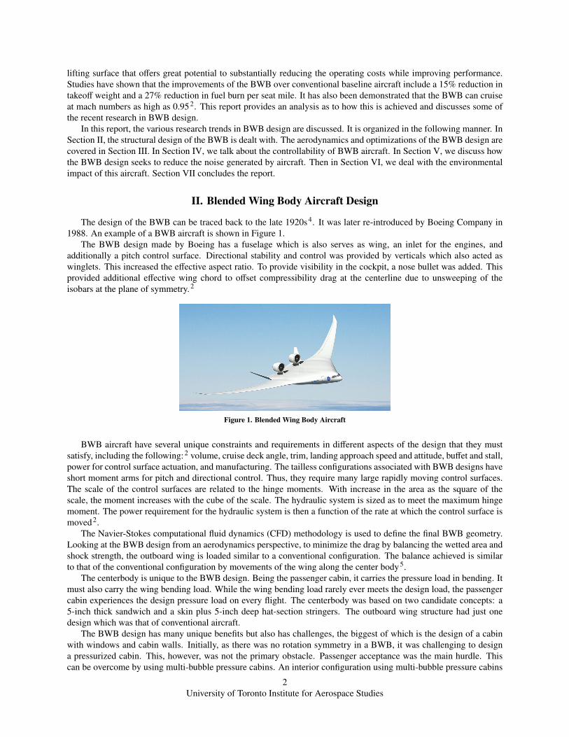
The design of the BWB can be traced back to the late 1920s4. It was later re-introduced by Boeing Company in1988. An example of a BWB aircraft is shown in Figure 1.
The BWB design made by Boeing has a fuselage which is also serves as wing, an inlet for the engines, andadditionally a pitch control surface. Directional stability and control was provided by verticals which also acted aswinglets. This increased the effective aspect ratio. To provide visibility in the cockpit, a nose bullet was added. Thisprovided additional effective wing chord to offset compressibility drag at the centerline due to unsweeping of theisobars at the plane of symmetry.2
Figure 1. Blended Wing Body Aircraft
BWB aircraft have several unique constraints and requirements in different aspects of the design that they mustsatisfy, including the following:2 volume, cruise deck angle, trim, landing approach speed and attitude, buffet and stall,power for control surface actuation, and manufacturing. The tailless configurations associated with BWB designs haveshort moment arms for pitch and directional control. Thus, they require many large rapidly moving control surfaces.The scale of the control surfaces are related to the hinge moments. With increase in the area as the square of thescale, the moment increases with the cube of the scale. The hydraulic system is sized as to meet the maximum hingemoment. The power requirement for the hydraulic system is then a function of the rate at which the control surface ismoved2.
The Navier-Stokes computational fluid dynamics (CFD) methodology is used to define the final BWB geometry.Looking at the BWB design from an aerodynamics perspective, to minimize the drag by balancing the wetted area andshock strength, the outboard wing is loaded similar to a conventional configuration. The balance achieved is similarto that of the conventional configuration by movements of the wing along the center body5.
The centerbody is unique to the BWB design. Being the passenger cabin, it carries the pressure load in bending. Itmust also carry the wing bending load. While the wing bending load rarely ever meets the design load, the passengercabin experiences the design pressure load on every flight. The centerbody was based on two candidate concepts: a5-inch thick sandwich and a skin plus 5-inch deep hat-section stringers. The outboard wing structure had just onedesign which was that of conventional aircraft.
The BWB design has many unique benefits but also has challenges, the biggest of which is the design of a cabinwith windows and cabin walls. Initially, as there was no rotation symmetry in a BWB, it was challenging to designa pressurized cabin. This, however, was not the primary obstacle. Passenger acceptance was the main hurdle. Thiscan be overcome by using multi-bubble pressure cabins. An interior configuration using multi-bubble pressure cabins
2University of Toronto Institute for Aerospace Studies

is shown in Figure 2. This configuration reduces weight through the use of strength dominated structures instead ofstiffness dominated structures. Segregation of the multi-bubble from the aerodynamic shell helps in making it strengthdominated6. The inner volume of the aerodynamic shell is significantly larger than that of the pressure vessel andthis would sustain the pressure loads. There are two types of multi-bubble configurations that were suggested by Voetet al.6 : an open-cell multi-bubble and a multi-bubble with pillars. Although an open-cell multi-bubble offers betterstructural integrity, the multi-bubble with pillars gives more space and better interiors. The design of the multi-bubbleuses the “Passenger Experience” approach6. In this method, passengers were subjected to various questionnairesand their views were recorded. The questionnaires included important interior aspects such as visibility of exit routes,window placement, comfort, and privacy. The popular opinion about windows was that the installation of LCD screenswhich display window views would compensate for the lack of actual windows. Another option was that there wouldbe a few windows that could be optimally shared among all passengers instead of the select few who would sit next tothem. This window area would be separated from the regular seating areas and would serve as a socializing spot. Thepresence of interior pillars and separation in the cabin was not a major issue according to the study.
Figure 2. Cross section of the multi-bubble concept 6
Passengers revealed that they are influenced by the experience of the journey, beginning from their entry into theaircraft up to their arrival at the destination airport. In order to address this concern, an entry and exit sequence asshown in Figure 3 was developed6. In this sequence, a bridge is created between the airport’s glass facade and thefoyer of the BWB with multi-bubble configuration. The large windows of the aircraft can be seen from the gate and,upon leaving the passenger bridge and entering the cabin, the gate’s facade can be seen through the windows of theBWB. This enables the passengers to link the orientation of the front windows (which are curved and placed under anangle from the direction of flight) to the expected movement of the aircraft and the location and direction of their seatin space.
Figure 3. Entry sequence and perceived spatial heights 6
A wide oval cabin design as shown in Figure 4 is an alternative7 to the multi-bubble concept. The cross-section ofthe oval cabin is formed by four arcs of different radii. The tension and compression loads are carried by a box structurethat is present at the interconnections of the nodes of the arch. This concept is both aerodynamically and structurallyfeasible since the member of the prismatic box structure forms the passenger floor. This oval design has severaladvantages: the emergency exits are easy to design and the problem of passenger comfort is solved with the ability toprovide an uninterrupted view. This design is also structurally efficient. However, the design is hard to manufactureand it has a large weight penalty. It also compromises on the aerodynamic efficiency offered by BWB design due to itsstructural requirements. While this design has potential, it has several issues as stated and needs further investigationto achieve a better aerodynamic efficiency and to improve the overall performance of the aircraft7.
3University of Toronto Institute for Aerospace Studies
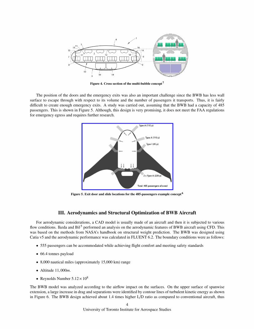
Figure 4. Cross section of the multi-bubble concept 7
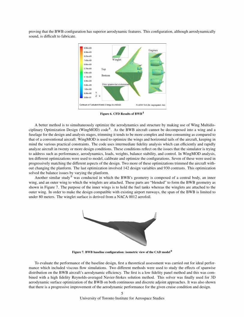
The position of the doors and the emergency exits was also an important challenge since the BWB has less wallsurface to escape through with respect to its volume and the number of passengers it transports. Thus, it is fairlydifficult to create enough emergency exits. A study was carried out, assuming that the BWB had a capacity of 485passengers. This is shown in Figure 5. Although, this design is very promising, it does not meet the FAA regulationsfor emergency egress and requires further research.
Figure 5. Exit door and slide locations for the 485-passengers example concept 6
III. Aerodynamics and Structural Optimization of BWB Aircraft
For aerodynamic considerations, a CAD model is usually made of an aircraft and then it is subjected to variousflow conditions. Ikeda and Bil5 performed an analysis on the aerodynamic features of BWB aircraft using CFD. Thiswas based on the methods from NASA’s handbook on structural weight prediction. The BWB was designed usingCatia v5 and the aerodynamic performance was calculated in FLUENT 6.2. The boundary conditions were as follows:
• 555 passengers can be accommodated while achieving flight comfort and meeting safety standards
• 66.4 tonnes payload
• 8,000 nautical miles (approximately 15,000 km) range
• Altitude 11,000m.
• Reynolds Number 5.12×10⁸
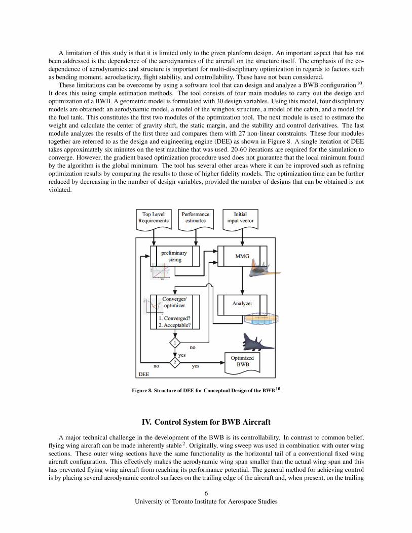
The BWB model was analyzed according to the airflow impact on the surfaces. On the upper surface of spanwiseextension, a large increase in drag and separations were identified by contour lines of turbulent kinetic energy as shownin Figure 6. The BWB design achieved about 1.4 times higher L/D ratio as compared to conventional aircraft, thus
4University of Toronto Institute for Aerospace Studies
proving that the BWB configuration has superior aerodynamic features. This configuration, although aerodynamicallysound, is difficult to fabricate.
Figure 6. CFD Results of BWB 5
A better method is to simultaneously optimize the aerodynamics and structure by making use of Wing Multidis-ciplinary Optimization Design (WingMOD) code8. As the BWB aircraft cannot be decomposed into a wing and afuselage for the design and analysis stages, trimming it tends to be more complex and time-consuming as compared tothat of a conventional aircraft. WingMOD is used to optimize the wings and horizontal tails of the aircraft, keeping inmind the various practical constraints. The code uses intermediate fidelity analysis which can efficiently and rapidlyanalyze aircraft in twenty or more design conditions. These conditions reflect on the issues that the simulator is tryingto address such as performance, aerodynamics, loads, weights, balance stability, and control. In WingMOD analysis,ten different optimizations were used to model, calibrate and optimize the configurations. Seven of these were used inprogressively matching the different aspects of the design. Two more of these optimizations trimmed the aircraft with-out changing the planform. The last optimization involved 142 design variables and 930 contrasts. This optimizationsolved the balance issues by varying the planform.
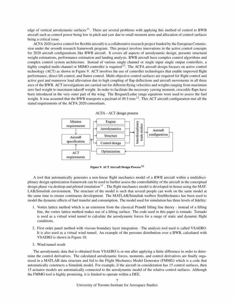
Another similar study9 was conducted in which the BWB’s geometry is composed of a central body, an innerwing, and an outer wing to which the winglets are attached. These parts are “blended” to form the BWB geometry asshown in Figure 7. The purpose of the inner wings is to hold the fuel tanks whereas the winglets are attached to theouter wing. In order to make the design compatible with existing airport runways, the span of the BWB is limited tounder 80 meters. The winglet surface is derived from a NACA 0012 aerofoil.
Figure 7. BWB baseline configuration: isometric view of the CAD model 9
To evaluate the performance of the baseline design, first a theoretical assessment was carried out for ideal perfor-mance which included viscous flow simulations. Two different methods were used to study the effects of spanwisedistribution on the BWB aircraft’s aerodynamic efficiency. The first is a low fidelity panel method and this was com-bined with a high fidelity Reynolds-averaged Navier-Stokes solution method. This solver was finally used for 3Daerodynamic surface optimization of the BWB on both continuous and discrete adjoint approaches. It was also shownthat there is a progressive improvement of the aerodynamic performance for the given cruise condition and design.
5University of Toronto Institute for Aerospace Studies
A limitation of this study is that it is limited only to the given planform design. An important aspect that has notbeen addressed is the dependence of the aerodynamics of the aircraft on the structure itself. The emphasis of the co-dependence of aerodynamics and structure is important for multi-disciplinary optimization in regards to factors suchas bending moment, aeroelasticity, flight stability, and controllability. These have not been considered.
These limitations can be overcome by using a software tool that can design and analyze a BWB configuration10.It does this using simple estimation methods. The tool consists of four main modules to carry out the design andoptimization of a BWB. A geometric model is formulated with 30 design variables. Using this model, four disciplinarymodels are obtained: an aerodynamic model, a model of the wingbox structure, a model of the cabin, and a model forthe fuel tank. This constitutes the first two modules of the optimization tool. The next module is used to estimate theweight and calculate the center of gravity shift, the static margin, and the stability and control derivatives. The lastmodule analyzes the results of the first three and compares them with 27 non-linear constraints. These four modulestogether are referred to as the design and engineering engine (DEE) as shown in Figure 8. A single iteration of DEEtakes approximately six minutes on the test machine that was used. 20-60 iterations are required for the simulation toconverge. However, the gradient based optimization procedure used does not guarantee that the local minimum foundby the algorithm is the global minimum. The tool has several other areas where it can be improved such as refiningoptimization results by comparing the results to those of higher fidelity models. The optimization time can be furtherreduced by decreasing in the number of design variables, provided the number of designs that can be obtained is notviolated.
Figure 8. Structure of DEE for Conceptual Design of the BWB 10
IV. Control System for BWB Aircraft
A major technical challenge in the development of the BWB is its controllability. In contrast to common belief,flying wing aircraft can be made inherently stable2. Originally, wing sweep was used in combination with outer wingsections. These outer wing sections have the same functionality as the horizontal tail of a conventional fixed wingaircraft configuration. This effectively makes the aerodynamic wing span smaller than the actual wing span and thishas prevented flying wing aircraft from reaching its performance potential. The general method for achieving controlis by placing several aerodynamic control surfaces on the trailing edge of the aircraft and, when present, on the trailing
6University of Toronto Institute for Aerospace Studies
edge of vertical aerodynamic surfaces11. There are several problems with applying this method of control to BWBaircraft such as control power being low in pitch and yaw due to small moment arms and allocation of control surfacesbeing a critical issue.
ACFA 2020 (active control for flexible aircraft) is a collaborative research project funded by the European Commis-sion under the seventh research framework program. This project involves innovations in the active control conceptsfor 2020 aircraft configurations like BWB aircraft. It covers all aspects of aerodynamic design, presents structuralweight estimations, performance estimation and landing analysis. BWB aircraft have complex control algorithms andcomplex control system architecture. Instead of various single channel or single input single output controllers, ahighly coupled multi-channel or MIMO controller is required12. The ACFA aircraft design focuses on active controltechnology (ACT) as shown in Figure 9. ACT involves the use of controller technologies that enable improved flightperformance, direct lift control, and flutter control. Multi-objective control surfaces are required for flight control andactive gust and maneuver load alleviation due to high coupling of flap deflections and aircraft movements in all threeaxes of the BWB. ACT investigations are carried out for different flying velocities and weights ranging from maximumzero fuel weight to maximum takeoff weight. In order to facilitate the necessary yawing moment, crocodile flaps havebeen introduced in the very outer part of the wing. The Breguet/Leduc range equations were used to assess the fuelweight. It was assumed that the BWB transports a payload of 49.5 tons12. This ACT aircraft configuration met all thestated requirements of the ACFA 2020 consortium.
Figure 9. ACT Aircraft Design Process 12
A tool that automatically generates a non-linear flight mechanics model of a BWB aircraft within a multidisci-plinary design optimization framework can be used to further assess the controllability of the aircraft in the conceptualdesign phase via desktop and piloted simulation11 . The flight mechanics model is developed in-house using the MAT-LAB/Simulink environment. The structure of the model is such that several people can work on the same model atthe same time to ensure continuous development. The MATLAB/Simulink toolbox SimMechanics has been used tomodel the dynamic effects of fuel transfer and consumption. The model used for simulation has three levels of fidelity:
1. Vortex lattice method which is an extension from the classical Prandtl lifting line theory - instead of a liftingline, the vortex lattice method makes use of a lifting surface. The code used in this paper is tornado. Tornadois used as a virtual wind tunnel to calculate the aerodynamic forces for a range of static and dynamic flightconditions.
2. First order panel method with viscous boundary layer integration - The analysis tool used is called VSAERO.It is also used as a virtual wind tunnel. An example of the pressure distribution over a BWB, calculated withVSAERO is shown in Figure 10.
3. Wind tunnel result
The aerodynamic data that is obtained from VSAERO is re-run after applying a finite difference in order to deter-mine the control derivatives. The calculated aerodynamic forces, moments, and control derivatives are finally orga-nized in a MATLAB data structure and fed to the Flight Mechanics Model Generator (FMMG) which is a code thatautomatically constructs a Simulink model. For example, if the aircraft in consideration has 15 control surfaces, then15 actuator models are automatically connected to the aerodynamic model of the relative control surfaces. Althoughthe FMMG tool is highly promising, it is limited to operate within a DEE.
7University of Toronto Institute for Aerospace Studies
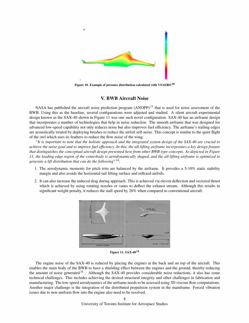
Figure 10. Example of pressure distribution calculated with VSAERO 10
V. BWB Aircraft Noise
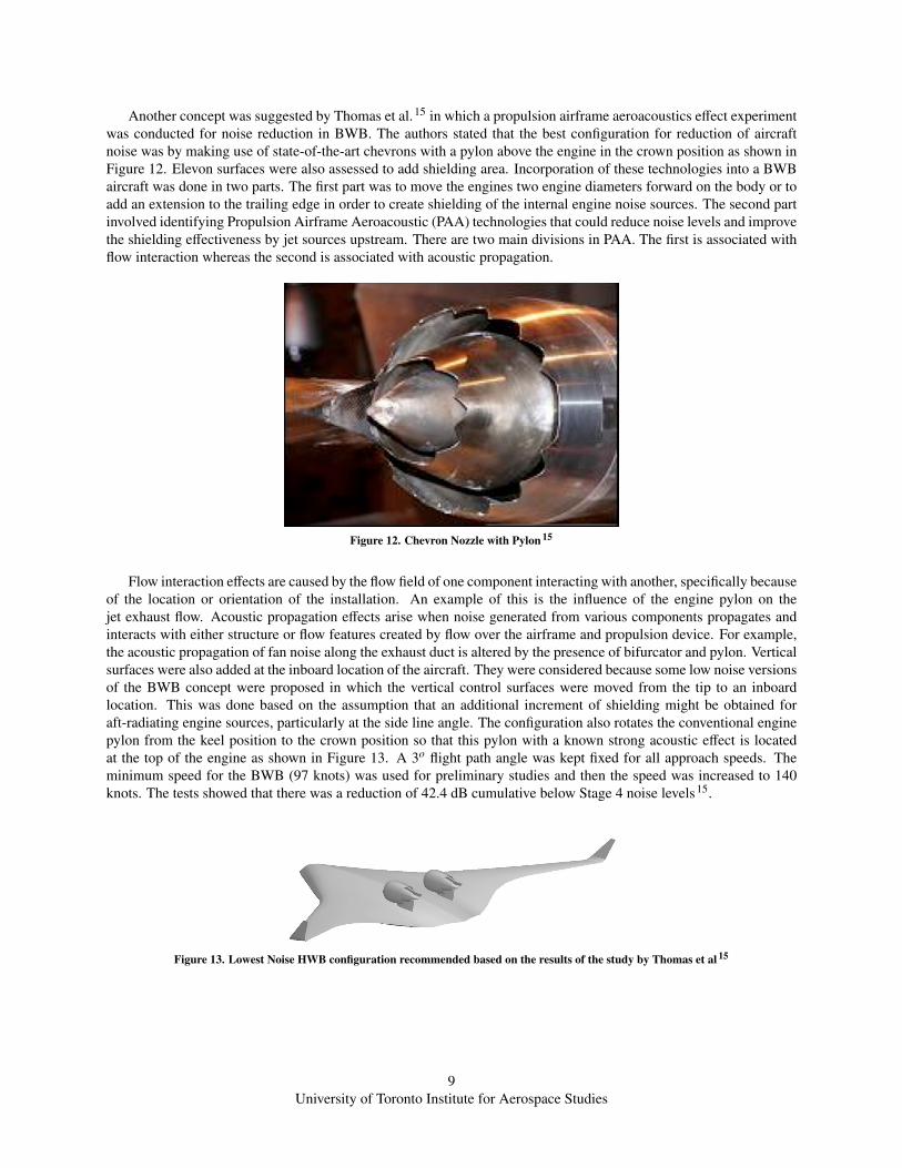
NASA has published the aircraft noise prediction program (ANOPP)13 that is used for noise assessment of theBWB. Using this as the baseline, several configurations were adjusted and studied. A silent aircraft experimentaldesign known as the SAX-40 shown in Figure 11 was one such novel configuration. SAX-40 has an airframe designthat incorporates a number of technologies that help in noise reduction. The smooth airframe that was designed foradvanced low-speed capability not only reduces noise but also improves fuel efficiency. The airframe’s trailing edgesare acoustically treated by deploying brushes to reduce the airfoil self-noise. This concept is similar to the quiet flightof the owl which uses its feathers to reduce the flow noise of the wing.
“It is important to note that the holistic approach and the integrated system design of the SAX-40 are crucial toachieve the noise goal and to improve fuel efficiency. In this, the all-lifting airframe incorporates a key design featurethat distinguishes the conceptual aircraft design presented here from other BWB-type concepts. As depicted in Figure11, the leading-edge region of the centerbody is aerodynamically shaped, and the all-lifting airframe is optimized togenerate a lift distribution that can do the following”14:
1. The aerodynamic moments for pitch trim are balanced by the airframe. It provides a 5-10% static stabilitymargin and also avoids the horizontal-tail lifting surface and reflexed airfoils.
2. It can also increase the induced drag during approach. This is achieved via elevon deflection and vectored thrustwhich is achieved by using rotating nozzles or vanes to deflect the exhaust stream. Although this results insignificant weight penalty, it reduces the stall speed by 28% when compared to conventional aircraft.
Figure 11. SAX-40 14
The engine noise of the SAX-40 is reduced by placing the engines at the back and on top of the aircraft. Thisenables the main body of the BWB to have a shielding effect between the engines and the ground, thereby reducingthe amount of noise generated14 . Although the SAX-40 provides considerable noise reductions, it also has sometechnical challenges. This includes achieving the desired structural integrity and other challenges in fabrication andmanufacturing. The low-speed aerodynamics of the airframe needs to be assessed using 3D viscous flow computations.Another major challenge is the integration of the distributed propulsion system in the mainframe. Forced vibrationissues due to non-uniform flow into the engine also need to be resolved.
8University of Toronto Institute for Aerospace Studies
Another concept was suggested by Thomas et al.15 in which a propulsion airframe aeroacoustics effect experimentwas conducted for noise reduction in BWB. The authors stated that the best configuration for reduction of aircraftnoise was by making use of state-of-the-art chevrons with a pylon above the engine in the crown position as shown inFigure 12. Elevon surfaces were also assessed to add shielding area. Incorporation of these technologies into a BWBaircraft was done in two parts. The first part was to move the engines two engine diameters forward on the body or toadd an extension to the trailing edge in order to create shielding of the internal engine noise sources. The second partinvolved identifying Propulsion Airframe Aeroacoustic (PAA) technologies that could reduce noise levels and improvethe shielding effectiveness by jet sources upstream. There are two main divisions in PAA. The first is associated withflow interaction whereas the second is associated with acoustic propagation.
Figure 12. Chevron Nozzle with Pylon 15
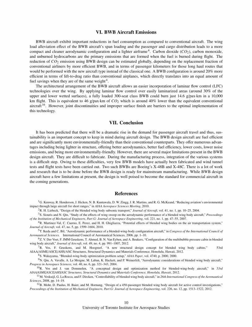
Flow interaction effects are caused by the flow field of one component interacting with another, specifically becauseof the location or orientation of the installation. An example of this is the influence of the engine pylon on thejet exhaust flow. Acoustic propagation effects arise when noise generated from various components propagates andinteracts with either structure or flow features created by flow over the airframe and propulsion device. For example,the acoustic propagation of fan noise along the exhaust duct is altered by the presence of bifurcator and pylon. Verticalsurfaces were also added at the inboard location of the aircraft. They were considered because some low noise versionsof the BWB concept were proposed in which the vertical control surfaces were moved from the tip to an inboardlocation. This was done based on the assumption that an additional increment of shielding might be obtained foraft-radiating engine sources, particularly at the side line angle. The configuration also rotates the conventional enginepylon from the keel position to the crown position so that this pylon with a known strong acoustic effect is locatedat the top of the engine as shown in Figure 13. A 3o flight path angle was kept fixed for all approach speeds. Theminimum speed for the BWB (97 knots) was used for preliminary studies and then the speed was increased to 140knots. The tests showed that there was a reduction of 42.4 dB cumulative below Stage 4 noise levels15.
Figure 13. Lowest Noise HWB configuration recommended based on the results of the study by Thomas et al 15
9University of Toronto Institute for Aerospace Studies
VI. BWB Aircraft Emissions
BWB aircraft exhibit important reductions in fuel consumption as compared to conventional aircraft. The wingload alleviation effect of the BWB aircraft’s span loading and the passenger and cargo distribution leads to a morecompact and cleaner aerodynamic configuration and a lighter airframe4. Carbon dioxide (CO2), carbon monoxide,and unburned hydrocarbons are the primary emissions that are formed when the fuel is burned during flight. Thereduction of CO2 emission using BWB design can be estimated globally, depending on the replacement fraction ofconventional airliners by more efficient BWB, and in terms of passenger kilometers for those long haul routes thatwould be performed with the new aircraft type instead of the classical one. A BWB configuration is around 20% moreefficient in terms of lift-to-drag ratio than conventional airplanes, which directly translates into an equal amount offuel savings when they are of the same weight4.
The architectural arrangement of the BWB aircraft allows an easier incorporation of laminar flow control (LFC)technologies over the wing. By applying laminar flow control over easily laminarized areas (around 30% of theupper and lower wetted surfaces), a fully loaded 300-seat class BWB could burn just 14.6 g/pax·km in a 10,000km flight. This is equivalent to 46 g/pax·km of CO2 which is around 40% lower than the equivalent conventionalaircraft16. However, joint discontinuities and improper surface finish are barriers to the optimal implementation ofthis technology.
VII. Conclusion
It has been predicted that there will be a dramatic rise in the demand for passenger aircraft travel and thus, sus-tainability is an important concept to keep in mind during aircraft design. The BWB design aircraft are fuel efficientand are significantly more environmentally-friendly than their conventional counterparts. They offer numerous advan-tages including being lighter in structure, offering better aerodynamics, better fuel efficiency, lower costs, lower noiseemissions, and being more environmentally-friendly. However, there are several major limitations present in the BWBdesign aircraft. They are difficult to fabricate. During the manufacturing process, integration of the various systemsis a difficult step. Owing to these difficulties, very few BWB models have actually been fabricated and wind tunneltests and flight tests have been carried out. Two such BWBs are Boeing’s X-48B and X-48C. There is a lot of workand research that is to be done before the BWB design is ready for mainstream manufacturing. While BWB designaircraft have a few limitations at present, the design is well poised to become the standard for commercial aircraft inthe coming generations.
References1G. Kenway, R. Henderson, J. Hicken, N. B. Kuntawala, D. W. Zingg, J. R. Martins, and R. G. McKeand, “Reducing aviation’s environmental
impact through large aircraft for short ranges,” in AIAA Aerospace Sciences Meeting, 2010.2R. H. Liebeck, “Design of the blended wing body subsonic transport,” Journal of Aircraft, vol. 41, no. 1, pp. 10–25, 2004.3S. Siouris and N. Qin, “Study of the effects of wing sweep on the aerodynamic performance of a blended wing body aircraft,” Proceedings
of the Institution of Mechanical Engineers, Part G: Journal of Aerospace Engineering, vol. 221, no. 1, pp. 47–55, 2007.4R. Martinez-Val, C. Cuerno, E. Perez, and H. H. Ghigliazza, “Potential effects of blended wing bodies on the air transportation system,”
Journal of Aircraft, vol. 47, no. 5, pp. 1599–1604, 2010.5T. Ikeda and C. Bil, “Aerodynamic performance of a blended-wing-body configuration aircraft,” in Congress of the International Council of
Aeronautical Sciences. International Council of Aeronautical Sciences, 2006, pp. 1–10.6Z. V. Der Voet, F. JMM Geuskens, T. Ahmed, B. N. Van Eyben, and A. Beukers, “Configuration of the multibubble pressure cabin in blended
wing body aircraft,” Journal of Aircraft, vol. 49, no. 4, pp. 991–1007, 2012.7R. Vos, F. Geuskens, and M. Hoogreef, “A new structural design concept for blended wing body cabins.” 53rd
AIAA/ASME/ASCE/AHS/ASC Structures, Structural Dynamics and Materials Conference, Honolulu, Hawaii, 2012.8S. Wakayama, “Blended-wing-body optimization problem setup,” AIAA Paper, vol. 4740, p. 2000, 2000.9N. Qin, A. Vavalle, A. Le Moigne, M. Laban, K. Hackett, and P. Weinerfelt, “Aerodynamic considerations of blended wing body aircraft,”
Progress in Aerospace Sciences, vol. 40, no. 6, pp. 321–343, 2004.10R. Vos and J. van Dommelen, “A conceptual design and optimization method for blended-wing-body aircraft,” in 53rd
AIAA/ASME/ASCE/AHS/ASC Structures, Structural Dynamics and Materials Conference, Honolulu, Hawaii, 2012.11M. Voskuijl, G. La Rocca, and F. Dircken, “Controllability of blended wing body aircraft,” in 26th International Congress of the Aeronautical
Sciences, 2008, pp. 14–19.12B. Mohr, D. Paulus, H. Baier, and M. Hornung, “Design of a 450-passenger blended wing body aircraft for active control investigations,”
Proceedings of the Institution of Mechanical Engineers, Part G: Journal of Aerospace Engineering, vol. 226, no. 12, pp. 1513–1522, 2012.
10University of Toronto Institute for Aerospace Studies

13W. E. Zorumski and D. S. Weir, “Aircraft noise prediction program theoretical manual: Propeller aerodynamics and noise,” Unknown, vol. 1,1986.
14J. Hileman, Z. Spakovszky, M. Drela, M. Sargeant, and A. Jones, “Airframe design for silent fuel-efficient aircraft,” Journal of aircraft,vol. 47, no. 3, pp. 956–969, 2010.
15R. H. Thomas, C. L. Burley, and E. D. Olson, “Hybrid wing body aircraft system noise assessment with propulsion airframe aeroacousticexperiments,” International Journal of Aeroacoustics, vol. 11, no. 3, pp. 369–410, 2012.
16A. Bolsunovsky, N. Buzoverya, B. Gurevich, V. Denisov, A. Dunaevsky, L. Shkadov, O. Sonin, A. Udzhuhu, and J. Zhurihin, “Flyingwing-problems and decisions,” Aircraft design, vol. 4, no. 4, pp. 193–219, 2001.
11University of Toronto Institute for Aerospace Studies