Embed Size (px)
Citation preview

An ammonia plant can be controlled economically by standardelectronic or pneumatic instrumentation.
J. A. Gremillion, The Foxboro Co., Foxboro, Mass.
The process control computer for chemical plant controlwas born in an ammonia plant. Numerous papers over theyears have extolled the computer and the great increases inproduction it could generate. More than 40 computersystems have been installed in ammonia plants worldwide.With evidence like this, why should the managers andengineers of the ammonia industry consider pneumatic orelectronic control as an alternative to the computer? Cancomputer control by replaced by conventional instru-ments?
The answer to the first question may be obvious; pneu-matic/electronic control equipment is cheaper than acomputer. The answer to the second question is yes, but theanswer is not so obvious nor is it universally accepted.
In those halcyon days of 20$ gas and $200 ammonia, onecould justify gold-lined piping if it meant more production.A process control computer hits the bull's-eye dead centeras far as the ability to eke out the last possible ounce ofproduction. With optimal algorithms, dead time compensa-tion, and the ability to optimize the plant on line viamathematical models, the computer is the process controlmedium capable of the best possible process control. But, isthe computer the optimum choice for ammonia plantcontrol?
Dead time compensation has been proposed for ammoniaplant control to overcome the dead time of the gas chro-matograph used to measure inert level in the synthesis loop.Demonstrated improvements in control of the inert levelresult from the application of gain-adaptive control. But itcosts money to engineer, implement, and maintain a controlloop with this level of complexity. How much extra pro-duction does the extra effort result in?
Assume a fictitious ammonia plant that is very sensitiveto the inert level in the loop, in which a change of 1 % inertwill affect production 10 ton/day (9.2 metric t/d). If the feedrate is raised 50% in one large step, a "conventional"control system based on pneumatic instruments willproduce 0.07 tons (63.5 kg) less than the more complex gainadaptive control system.
The cost/benefit ratio is too high to justify this scheme. Ifthe dead time of the analyzer is a bother, why not get rid ofthe analyzer? Infrared or mass spectrometer devices can
Figure 1. The hierarchy of controlcapability.
0360-7275/79/1753-0037 $01.00 ® 1979 AIChE
Figure 2. A change in set point onolder pneumatic instruments wouldcause a derivative bump.
44

provide a continuous reading of methane level in thesynthesis loop yielding improved control and reducingfarther the small incentive for the more complex dead timecompensating control.
On-line optimization is the largest of the sacred cows. For13 years, the dream of an ammonia plant running at maxi-mum rate or minimum cost, automatically adjusting thebasic plant parameters to compensate for changes inweather or ammonia prices, has been offered as the ultimatejustification and use for a computer system. Where is theon-line optimized ammonia plant?
On-line optimization of the ammonia process has beenunsuccessful for several reasons:
1. The models required to effect optimization arecomplex and thus expensive to program and maintain.
2. The computers sold to most ammonia plants are toosmall to support optimization.
3. The market conditions during the period in whichoptimization was considered were such that most of theplant parameters had "optimum" set points at theirconstraining limits.
4. Most of the benefits reported attained from computercontrol are derivable from simple, proven regulatory controlof key plant parameters.
The last point is the key argument of this article; most ofthe benefits of computer control can be obtained by betterregulatory control of the process at a much lower cost/bene-fit ratio than can be achieved by exotic control algorithmsor optimization schemes. The basic regulatory control of anammonia plant can be most economically achieved throughstandard instrumentation, electronic or pneumatic.
Pneumatic magicIn the hierarchy of capabilities for process control, as
seen in Figure 1, the computer ranks first in the sophistica-tion of control available. Next follows electronic controllers,then pneumatic controllers, and then, finally, manualcontrol.
G>K
ƒ
K
ƒ
Figure 3. Undesirable response canoccur if the upstream controller callsfor the downstream controller tochange faster than it is capable ofdoing.
Most of the benefits attributed for years to computercontrol of the ammonia process can be produced by regula-tory control using a computer, electronic instruments, orpneumatic instruments. Since the majority of ammoniaplants are instrumented pneumatically, the discussion ofthe control loops will assume a pneumatic system.
Last year, Lloyd Skaggs of Kellogg presented the resultsof a survey among operators of ammonia plants detailingwhat they found to be the most severe control problems. (1)The top five problems reported were hydrogen-to-nitrogenratio, steam-to-gas ratio, purge, air compressor antisurge,and methane leakage.
With the exception of the antisurge control, these controlsystems have traditionally been implemented by computer.The reason for the proliferation of computer systems forammonia plants is more than merely the justification forcomplex control. The computer was originally appliedbecause pneumatic controllers had problems whichprecluded their use in the necessary control schemes.
In the 20 years since they were first chosen for ammoniacontrol, computers have come a long way, but so havepneumatic controllers:
1. The long time constants found in ammonia plantsrequire the use of derivative on some controllers. On oldertypes of pneumatic instruments, a "bump" would occurwhenever the set point was changed on a controller withderivative action, as seen in Figure 2. The modern pneu-matic controller has derivative action based on output andthere is no longer a derivative bump problem.
2. Some of the control schemes using cascade loops"wind up" when the downstream controller cannot respondas fast as the upstream controller requires it to. The resultis the undesirable response depicted in Figure 3. Themodern pneumatic controller uses antiwindup features toprevent this problem from occurring.
3. Some of the control schemes for ammonia plantsrequire chromatographs for inputs. The computer wasneeded to interface to the older style of gas Chromatograph.
Modern analyzers provide single-stream, continuousoutput specifically designed for process control. There iseven a fully pneumatic analyzer, the pneumatic composi-tion transmitter (PCT), which is field-mounted; no analyzerhouse is required, as shown in Figure 4.
Over the years, the expectation as to what type ofcomputer control can be economically applied to the ammo-nia process has come down. The capability of pneumaticcontrol during that same period has come up. Today, pneu-matic instrumentation can provide the control previouslydone through computers.
The first loop to be converted to pneumatic is the controlsystem for the steam-to-gas ratio. This loop has beenapplied for years using pneumatics, as in the scheme shownin Figure 5. This arrangement can, however, cause problemsduring gas flow transients. If the steam withdraws tooquickly as the gas flow decreases, gas may temporarily rushinto the reformer, causing a low steam-to-gas ratio.
To provide protection from low steam-to-gas ratios in thesimplest possible manner, a unique scheme, devised byCarroll Ryskamp of Foxboro and depicted in Figure 6, isemployed. This scheme is the same as the basic ratioscheme, Figure 5, except for the addition of a lag unit andhigh selector relay.
The set point for the steam controller is normally deter-mined by multiplying the gas flow by a constant, thesteam-to-gas ratio. The lag unit intercepts the set point ofthe steam flow controller and delays its rise or fall. If the gasflow is lowered by the operator or some other controlscheme, the signals at the high selector are the "normal"signal which dropped immediately, and the signal throughthe lag which is the largest value since the lag unit causesthe signal to drop slowly. The lag unit thus determines thecircuit and the steam withdraws slowly.
45

Figure 4.The pneu-matic compo-sition trans-mitter (PCT)is totallypneumaticand needs noanalyzerhouse.
If the gas is increased, the signal through the lag unit risesslower than the "normal" signal, taking the lag unit out ofthe circuit and allowing steam to enter the reformer imme-diately.
Control scheme additionsThe steam-to-gas control scheme shown in Figure 6 is
simple, inexpensive, and adequate for most plants. If,however, other conditions^ in the plant may cause the ratioto be in error, additions to the control scheme may beneeded. The most common problem is natural gas composi-tion upsets. If the higher hydrocarbons increase in theprocess gas, more steam will be required to hold a saferatio.
Figure 7 shows the ratio control scheme from Figure 6with the addition of a Chromatograph with a pneumaticoutput of ethane and propane composition, which adjuststhe gas rate to correspond to the carbon flow rate. Thescheme should then be called steam-to-carbon ratio control.Similarly, corrections can be made to compensate for natu-ral gas temperature changes or steam pressure changes, asseen in Figure 8.
Skagg reports that 85% of those surveyed picked thehydrogen-to-nitrogen ratio as a difficult control problem.This loop should really not be that difficult to controlbecause the process response is primarily a lag plus a smallamount of dead time introduced by the analyzer. Control ofthe synthesis loop ratio, however, is beset by all of theproblems discussed previously as a part of past pneumaticinstrumentation—derivative bump, windup, and the needfor Chromatographie analyzers.
Since modern pneumatic instruments have solved theproblems of the past, the hydrogen-nitrogen loop should beimplementable in modern pneumatics; Figure 9 shows thehydrogen-to-nitrogen ratio scheme for a plant that is neverair limited.
In this scheme, both of the ratios are determined bypneumatic chromatographs, PCT's, which transmit pneu-matic signals proportional to the hydrogen and nitrogencompositions in the synthesis loop and makeup gas. Acontroller on the synthesis loop ratio sets the set point ofthe makeup gas ratio controller. A tie-in with the measure-ment of the makeup gas ratio prevents the synthesis loopcontroller with winding up. The makeup ratio controllersets the air-to-gas ratio which, when multiplied by the gasflow, sets the air flow set point. This is similar to schemesdesigned for implementation in computer software.
STEAM-TO-GAS RATIO
Figure 5. The traditional steam-to-gas control loop.
If very few (or very slow) upsets occur because of themakeup ratio, the scheme may be simplified by allowing thesynthesis loop ratio controller to set the air-to-gas ratiodirectly. This simplified scheme saves one PCT and onecontroller but may control more poorly than the triple-cascade scheme in Figure 9. This discussion, however,stresses that enhancements to control must enhance profit.If upsets from the front end of the plant are-^low or rare, thesingle feedback controller will provide good control with anequipment savings of about $9,000 over the multi-cascadescheme.
If the plant is air-limited for a portion of the time, thehydrogen-to-nitrogen ratio scheme must be coupled withthe scheme which sets the gas rate, the throughput control.Figure 10 shows a typical throughput control scheme in
46

which the gas rate is set by either the plant constraint (saysyngas compressor suction pressure) or a maximum naturalgas demand.
To adjust the gas during periods of air limited operation,the throughput scheme is coupled to the ratio scheme by a
Figure 6. Steam-to-gas control withprotection from transients.
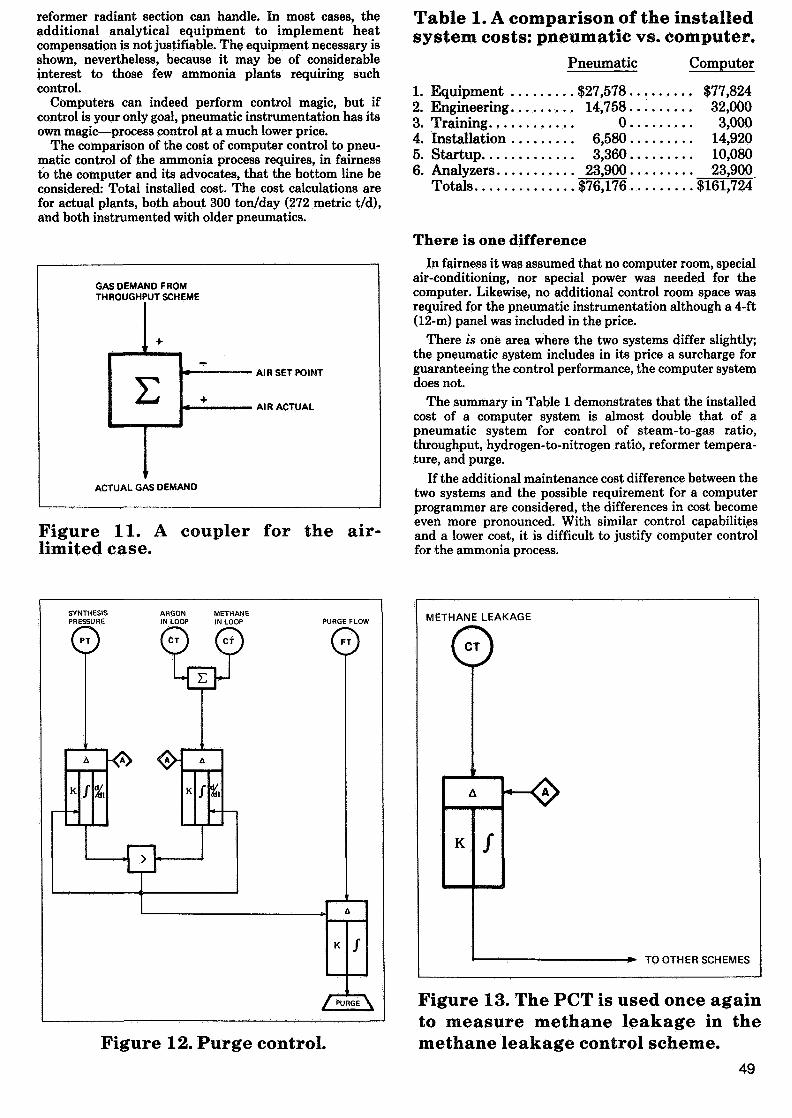
universal summer as shown in Figure 11. This technique,developed by Carroll Ryskamp of The Foxboro Co., allowsthe plant to always operate at the maximum gas rate as setby either the constraint, the gas demand limit, or thehydrogen-to-nitrogen ratio. If the air measurement and airset point are equal, they cancel out in the relay and the gasdemand is set by the constraint or gas rate controllers. If theair compressor cannot deliver the air required to maintainthe ratio, the measurement and set point will differ and anegative bias will be applied to the gas flow set point 10control the ratio.
Purge control is similarA scheme similar to the rate auto-selector scheme of
Figure 10 is also used to control the purge. Figure 12 showsthe purge control system in which either the synthesis looppressure or inerj; level sets the purge flow rate. The operatorsets the maximum pressure on the pressure controller andthe optimum inert level on the inert controller. The purgeneeded to hold both values, pressure and inert, at or belowtheir set points is set by the two controllers. The purge isthus always at optimum.
Methane leakage is most commonly controlled by holdingstearn-to-gas ratio and primary reformer exit temperatureconstant. Since the reforming reaction goes to equilibrium,the methane leakage from the primary reformer will be heldconstant if the temperature and ratio are held constant.
If, for some reason, it is desirable to adjust the primaryreformer exit temperature (or steam-to-gas ratio) to manip-ulate methane leakage at the secondary reformer effluent orsyngas compressor inlet, the control scheme in Figure 13may be used. Once again the pneumatic composition trans-mitter is used to measure methane. The signal from thePCT is measurement to a controller whose output sets theprimary reformer exit temperature, steam-to-gas ratio, oran override to the secondary reformer air flow dependingupon plant operation desires.
Since the most common method of methane leakagecontrol is either the automatic (through the scheme in
NATURAL GAS
Figure 7. The steam-to-gas controlscheme using the PCT to compensatefor natural gas composition changes.
NATURAL GAS
Figure 8. Steam-to-gas ratio controlwith compensation for gas tempera-ture and steam pressure.
47

H2 IN N2INLOOP LOOP
H2 IN N2INMAKEUP MAKEUP
Figure 9.The hydrogen-
to-nitrogenratio schemeusing PCT's.
AIR/GAS RATIO
TOTAL NATURAL GAS PLANT CONSTRAINT PROCESS GAS
0
Figure 10.Throughput
control.
Figure 13) or manual setting of the temperature exit of theprimary reformer, a typical temperature control scheme isshown in Figure 14. In this scheme, the temperaturecontroller sets the heat-to-gas flow ratio which, when multi-plied by the process gas flow compensated for reformerdynamics, yields the Btu (heat content) firing required tohold the temperature at the set point, subtracting the
48
contribution of purge gas fired in the reformer gives theheat required from the fuel. If the heat content of the fuel isconstant, the value from the subtracter may directly set thefuel flow.
Compensation for the heat content of the fuel may beneeded if upsets to the fuel heat value occur faster than thetemperature controller and slower than the capacity of the
reformer radiant section can handle. In most cases, theadditional analytical equipment to implement heatcompensation is not justifiable. The equipment necessary isshown, nevertheless, because it may be of considerableinterest to those few ammonia plants requiring suchcontrol.
Computers can indeed perform control magic, but ifcontrol is your only goal, pneumatic instrumentation has itsown magic—process control at a much lower price.
The comparison of the cost of computer control to pneu-matic control of the ammonia process requires, in fairnessto the computer and its advocates, that the bottom line beconsidered: Total installed cost. The cost calculations arefor actual plants, both about 300 ton/day (272 metric t/d),and both instrumented with older pneumatics.
GAS DEMAND FROMTHROUGHPUT SCHEME
• A I R SET POINT
AIR ACTUAL
ACTUAL GAS DEMAND
Figure 11. A coupler for the air-limited case.
Table 1. A comparison of the installedsystem costs: pneumatic vs. computer.
Pneumatic Computer
1. Equipment $27,578.2. Engineering 14,758.3. Training 0,4. Installation 6,580.5. Startup 3,360,6. Analyzers 23,900
$77,82432,0003,000
14,92010,08023,900
Totals $76,176 $161,724
There is one differenceIn fairness it was assumed that no computer room, special
air-conditioning, nor special power was needed for thecomputer. Likewise, no additional control room space wasrequired for the pneumatic instrumentation although a 4-ft(12-m) panel was included in the price.
There is one area where the two systems differ slightly;the pneumatic system includes in its price a surcharge forguaranteeing the control performance, the computer systemdoes not.
The summary in Table 1 demonstrates that the installedcost of a computer system is almost double that of apneumatic system for control of steam-to-gas ratio,throughput, hydrogen-to-nitrogen ratio, reformer tempera-ture, and purge.
If the additional maintenance cost difference between thetwo systems and the possible requirement for a computerprogrammer are considered, the differences in cost becomeeven more pronounced. With similar control capabilitiesand a lower cost, it is difficult to justify computer controlfor the ammonia process.
Figure 12. Purge control.
METHANE LEAKAGE*—>
CT
K ƒ
TO OTHER SCHEMES
Figure 13. The PCT is used once againto measure methane leakage in themethane leakage control scheme.
49

FUEL
Figure 14.Reformer
exit temperaturecontrol withheat(Btu)
compensation.Btu/GAS RATIO
Table 2. A process management log.DateTimeH/N RatioProductionProduction Cost.
6/15/77 6/15/778:32.2.90.
1,035.6.$95.36.
13:212.85
1,036.5$94.71
Profit $25,517.18 $26,213,09
Change in profit = $695.91Change due to ratio change = $673.14
So, perhaps the statement should be made here that thecomputer has no place in the ammonia industry. Such astatement has one problem: It is false. Although pneumaticinstrumentation may be the economic optimum for controlof thé key plant variables, it fails miserably in providing forthe other needs of plant management personnel.
The point has been made that the regulatory control ofkey ammonia plant variables can be most economicallyaccomplished by pneumatic instrumentation. There is,however, another realm of plant control in which thecomputer is the outstanding performer. Process manage-ment, the calculation and presentation of informationnecessary for management decisions on the operation of theprocess, is the ammonia control need, which may justify theadded expense of a computer system. I am referring here tologs and reports, long considered a secondary aspect ofcomputers in ammonia plants. Logs and reports from thecomputer serve as input to the "management controllers,"such as the operators and unit superintendents, who adjustthe process based upon those inputs.
An example best illustrates what the computer canprovide to aid in the management of the ammonia process.The goal of the unit superintendent in this example is todetermine the optimum hydrogen-to-nitrogen ratio so thata set point can be chosen for the pneumatic ratio controlscheme. Every day he directs that a different ratio be set onthe controller. Each morning he reviews the operators'reports to determine, based on his experience, whether thechange in ratio set point improved plant operation. Bytrial-and-error, he moves the plant toward the optimum.
Suppose the computer were to be programmed to include
the knowledge of the unit superintendent so that changes inproduction due to the ratio change could be isolated, remov-ing the effects of other plant variables such as cooling watertemperature and air humidity. A report depicting such acalculation is shown in Table 2.
With the information readily available to the operator, hethen can direct changes to the ratio setting as often as theprocess response will allow. Thus, the optimum is not onlyreached more rapidly, but the entire process is accom-plished without the need of management intervention. Theunit superintendent can now direct his efforts to solvingother management problems, such as calming the operatorsafter they see the profit the plant is making from the log inTable 2.
In conclusion
Even though the days of $48 ammonia selling for $200 aton are gone, there is still money to be realized in improvingthe control of the ammonia plant. Today, it is importantthat all possible solutions to the control problems of theprocess be evaluated.
If in the evaluation it is determined that process manage-ment inputs provided by the computer system can signifi-cantly improve plant profitability, the computer is theobvious choice for control as well. If it is determined thatbasic regulatory control is the need, save yourself somemoney and give pneumatic (or electronic) control a chance.
#
Literature cited1. Skaggs, L., "Computers in the Ammonia Industry-
at the Kellogg Ammonia Club (August, 1977).-A Review," presented
J. A. Gremillion, employed by The Foxboro Co.since 1976, is a graduate of Louisiana State Univ.,Baton Rouge. He has worked as a chemical indus-try specialist concentrating on fertilizer, metha-nol and VCM plants as well as a representative ofthe Analytical Div. of the firm at its Baton Rougelocation.
50