Embed Size (px)
Citation preview
An Alternative Analysis of Noise Folding in Fractional-N SynthesizersBehzad Razavi
Electrical Engineering DepartmentUniversity of California, Los Angeles, CA 90095, USA
Fig. 1. Generic fractional-N synthesizer showing the effect of CP mismatch.
'out
~.........
I p + M
2 0 ,Ic·;··········
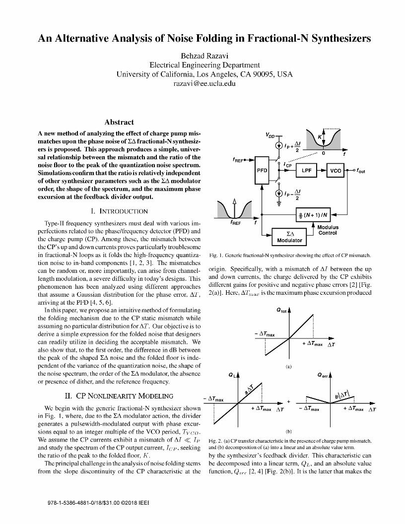
Fig. 2. (a) CP transfer characteristic in the presence of charge pump mismatch,and (b) decomposition of (a) into a linear and an absolute value term.
by the synthesizer's feedback divider. This characteristic canbe decomposed into a linear term, QL, and an absolute valuefunction, Qerr [2,4] [Fig. 2(b)]. It is the latter that makes the
origin. Specifically, with a mismatch of L1I between the upand down currents, the charge delivered by the CP exhibitsdifferent gains for positive and negative phase errors [2] [Fig.2(a)]. Here, L1Tmax is the maximum phase excursion produced
Qtot
-liTmax
+ liTmax liT
(a)
Q L Q err
-liTmax ++ liTmax liT -liTmax + liTmax liT
(b)
II. CP NONLINEARITY MODELING
Abstract
I. INTRODUCTION
We begin with the generic fractional-N synthesizer shownin Fig. 1, where, due to the LL1 modulator action, the dividergenerates a pulsewidth-modulated output with phase excursions equal to an integer multiple of the VCO period, Tvco.We assume the CP currents exhibit a mismatch of L1I ~ Ipand study the spectrum of the CP output current, Icp, seekingthe ratio of the peak to the folded floor, K.
The principal challenge in the analysis of noise folding stemsfrom the slope discontinuity of the CP characteristic at the
Type-II frequency synthesizers must deal with various imperfections related to the phase/frequency detector (PFD) andthe charge pump (CP). Among these, the mismatch betweenthe CP's up and down currents proves particularly troublesomein fractional-N loops as it folds the high-frequency quantization noise to in-band components [1, 2, 3]. The mismatchescan be random or, more importantly, can arise from channellength modulation, a severe difficulty in today's designs. Thisphenomenon has been analyzed using different approachesthat assume a Gaussian distribution for the phase error, L1T,arriving at the PFD [4, 5, 6].
In this paper, we propose an intuitive method of formulatingthe folding mechanism due to the CP static mismatch whileassuming no particular distribution for L1T. Our objective is toderive a simple expression for the folded noise that designerscan readily utilize in deciding the acceptable mismatch. Wealso show that, to the first order, the difference in dB betweenthe peak of the shaped LL1 noise and the folded floor is independent of the variance of the quantization noise, the shape ofthe noise spectrum, the order of the LL1 modulator, the absenceor presence of dither, and the reference frequency.
A new method of analyzing the effect of charge pump mismatches upon the phase noise of LL1 fractional-N synthesizers is proposed. This approach produces a simple, universal relationship between the mismatch and the ratio of thenoise floor to the peak of the quantization noise spectrum.Simulations confirm that the ratio is relatively independentof other synthesizer parameters such as the LL1 modulatororder, the shape of the spectrum, and the maximum phaseexcursion at the feedback divider output.
978-1-5386-4881-0/18/$31.00 ©2018 IEEE
(4)
+ ~Tmax ~T
Q err
- ~Tmax
b 2Qtot ~ aL1T + -'T'--L1T .
L1.Lmax
We must express a and b in termsofthe nominal CPcurrent, Ip,and the mismatch, L1I. We note that a = Ip and b = L1I/2.Since Qtot and the CP current, Icp in Fig. 1, are relatedby a factor of TREF = 1/IREF, we can still proceed withthe expression for Qtot even though we are interested in thespectrum of Icp.
Fig. 4. Fitting a polynomial to the absolute value function according to Eg.(I ).
Thus, Qtot in Fig. 2(a) can be written as
+11----
xx
y
analysis difficult.In [4], the nonlinearity is analyzed in the time domain and
the variance of the absolute value function's output is relatedto that of the input, assuming a Gaussian distribution for thelatter. The computations in [5] assume that the spectrum ofIL1TI is known. The analysis in [6] employs Price's theorem[7] to relate the autocorrelations of the input and output of anonlinear system with a Gaussian input.
In this paper, we wish to directly approximate Qerr = blL1TIby a polynomial. If successful, such an endeavor could thenreadily follow the standard nonlinearity analysis methods usedin RF design.
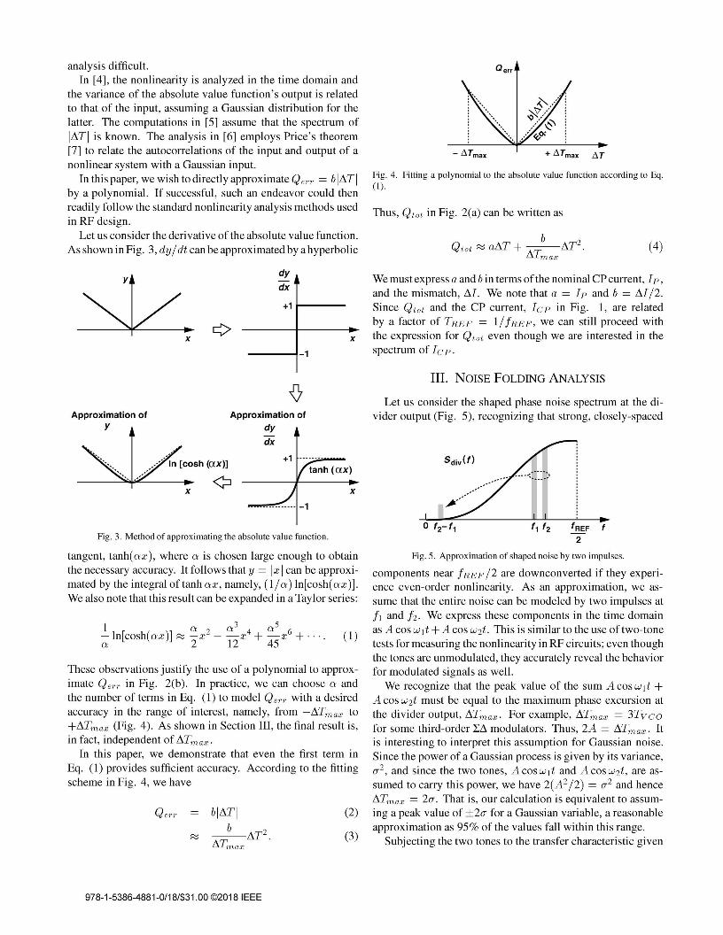
Let us consider the derivative of the absolute value function.As shown in Fig. 3, dy / dt can be approximated by a hyperbolic
dy
dx
III. NOISE FOLDING ANALYSIS
Fig. 3. Method of approximating the absolute value function.
Let us consider the shaped phase noise spectrum at the divider output (Fig. 5), recognizing that strong, closely-spaced
x
tanh (ax)
----------- -1
Approximation ofdy
dx
x
Approximation ofy
tangent, tanh(ax), where a is chosen large enough to obtainthe necessary accuracy. It follows that y = Ix Ican be approximated by the integral of tanh ax, namely, (l/a) In[cosh(ax)].We also note that this result can be expanded in a Taylor series:
These observations justify the use of a polynomial to approximate Qerr in Fig. 2(b). In practice, we can choose a andthe number of terms in Eq. (1) to model Qerr with a desiredaccuracy in the range of interest, namely, from -L1Tmax to+L1Tmax (Fig. 4). As shown in Section III, the final result is,in fact, independent of L1Tmax'
In this paper, we demonstrate that even the first term inEq. (1) provides sufficient accuracy. According to the fittingscheme in Fig. 4, we have
Qerr blL1TI_b_L1T2 .L1Tmax
(2)
(3)
Fig. 5. Approximation of shaped noise by two impulses.
components near IREF /2 are downconverted if they experience even-order nonlinearity. As an approximation, we assume that the entire noise can be modeled by two impulses atII and h. We express these components in the time domainas A cos wit +A cos W2t. This is similar to the use of two-tonetests for measuring the nonlinearity in RF circuits; even thoughthe tones are unmodulated, they accurately reveal the behaviorfor modulated signals as well.
We recognize that the peak value of the sum A cos wit +A cos W2t must be equal to the maximum phase excursion atthe divider output, L1Tmax . For example, L1Tmax = 3Tvcofor some third-order LL1 modulators. Thus, 2A = L1Tmax' Itis interesting to interpret this assumption for Gaussian noise.Since the power of a Gaussian process is given by its variance,(J'2, and since the two tones, A cos wit and A cos W2t, are assumed to carry this power, we have 2(A2/2) = (J'2 and henceL1Tmax = 2(J'. That is, our calculation is equivalent to assuming a peak value of ±2(J' for a Gaussian variable, a reasonableapproximation as 95% of the values fall within this range.
Subjecting the two tones to the transfer characteristic given
978-1-5386-4881-0/18/$31.00 ©2018 IEEE
by (4), we have-190 r--.....--...._...,--.....--..........""T'-.....,
i ·220U! ·230
Cl>'" -240'0z
Cl> ·250'"IIIii -260
·210
·200
·290 .....- .....------.....--......---..............- .......105
·190 r--.....---.........,......--............................---,
·280
·270
·210
·200
i ·220U! -230
Cl>'" -240'0zCl> -250'"IIIii ·260
(5)
(6)M
K = 4Ip
'
Qtot
For example, a 5% mismatch produces a floor 38 dB belowthe peak.
This universal expression reveals that, to the first order, K isindependent of other design parameters such as the maximumphase fluctuation at the divider output, the exact shape of thequantization noise spectrum, the LI1 modulator order, and thereference frequency.
In practice, we are also interested in the absolute in-bandnoise floor at the charge pump output. Since the peak of thequantization noise spectrum is known [4], it can be simplymUltiplied by K 2 to obtain the phase noise floor.
I1Tmax (a--2
- cos Wit + COSW2t) +b I1T2
---~(COswlt + COSW2t)2.I1Tmax 4
The folded component is therefore equal to (MTmax /4) cos(WI
W2)t, whose amplitude can be normalized to that of the maincomponents, aI1Tmax /2, yielding K = b/(2a). With the aand b values found in Section II, we have
·270
IV. SIMULATION RESULTS AND DISCUSSION -280
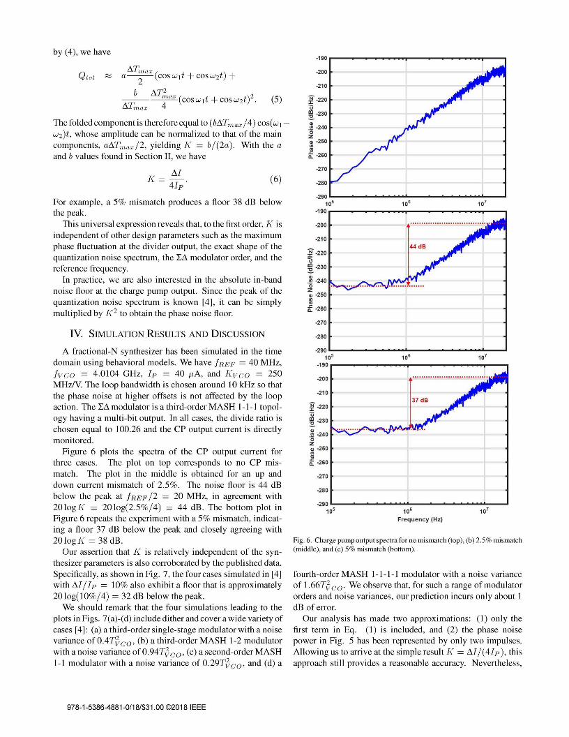
Fig. 6. Charge pump output spectra for no mismatch (top), (b) 2.5% mismatch(middle), and (c) 5% mismatch (bottom).
37 dB·210
·280
-270
i ·220U! ·230
Cl>'" ·240'0zCl> ·250'"IIIii ·260
-290 L.._..... ................__......_ ................_---'
1~ 1~ 1~Frequency (Hz)
-290 L.._..... ................__............................_---'
105
·190r--.....---.........,......--......--...........---,
·200
fourth-order MASH 1-1-1-1 modulator with a noise varianceof 1.66TJco' We observe that, for such a range of modulatororders and noise variances, our prediction incurs only about 1dB of error.
Our analysis has made two approximations: (1) only thefirst term in Eq. (1) is included, and (2) the phase noisepower in Fig. 5 has been represented by only two impulses.Allowing us to arrive at the simple result K = M / (4Ip ), thisapproach still provides a reasonable accuracy. Nevertheless,
A fractional-N synthesizer has been simulated in the timedomain using behavioral models. We have fREF = 40 MHz,fvco = 4.0104 GHz, Ip = 40 pA, and Kvco = 250MHz/V. The loop bandwidth is chosen around 10 kHz so thatthe phase noise at higher offsets is not affected by the loopaction. The LI1 modulator is a third-order MASH 1-1-1 topology having a multi-bit output. In all cases, the divide ratio ischosen equal to 100.26 and the CP output current is directlymonitored.
Figure 6 plots the spectra of the CP output current forthree cases. The plot on top corresponds to no CP mismatch. The plot in the middle is obtained for an up anddown current mismatch of 2.5%. The noise floor is 44 dBbelow the peak at fREF /2 = 20 MHz, in agreement with20logK = 20log(2.5%/4) = 44 dB. The bottom plot inFigure 6 repeats the experiment with a 5% mismatch, indicating a floor 37 dB below the peak and closely agreeing with20 log K = 38 dB.
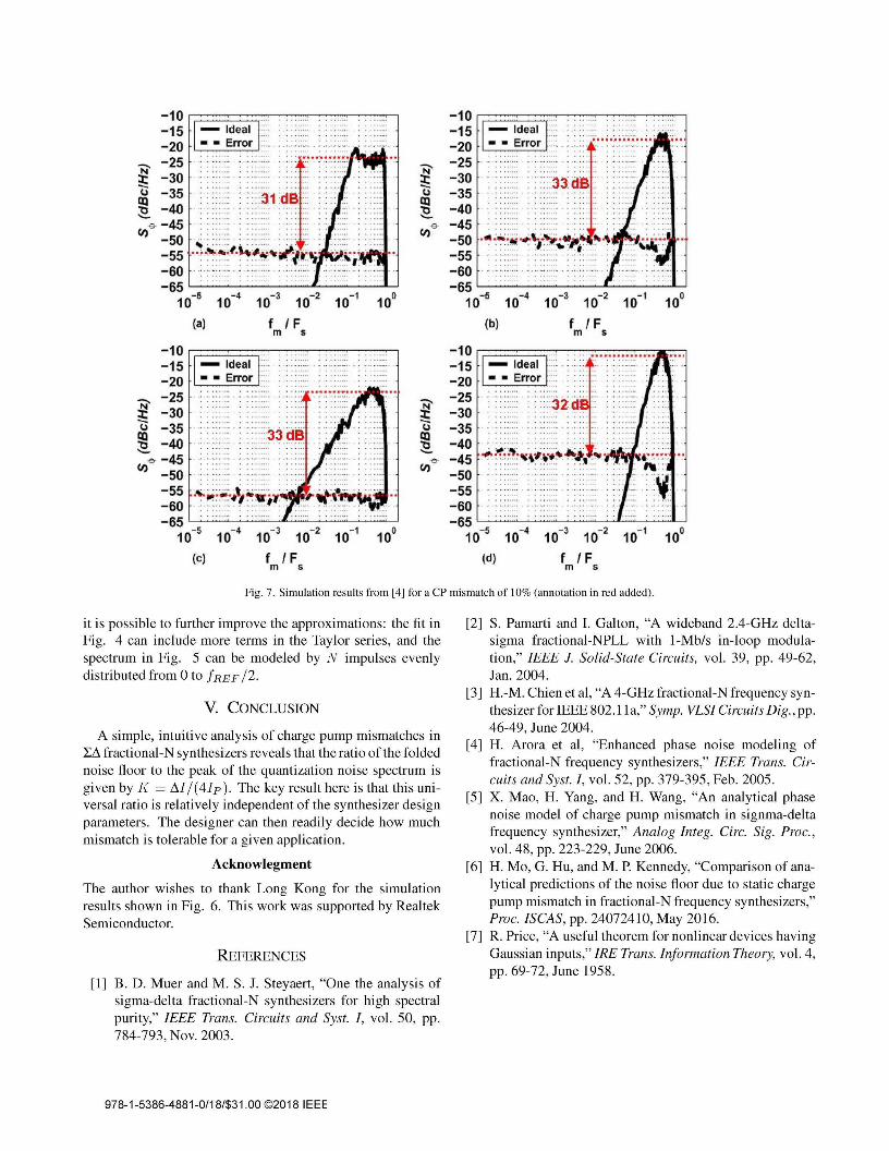
Our assertion that K is relatively independent of the synthesizer parameters is also corroborated by the published data.Specifically, as shown in Fig. 7, the four cases simulated in [4]with 111/Ip = 10% also exhibit a floor that is approximately20 log( 10%/4) = 32 dB below the peak.
We should remark that the four simulations leading to theplots in Figs. 7(a)-(d) include dither and cover a wide variety ofcases [4]: (a) a third-order single-stage modulator with a noisevariance ofOATJco, (b) a third-order MASH 1-2 modulatorwith a noise variance ofO.94TJco' (c) a second-order MASH1-1 modulator with a noise variance of 0.29TJco' and (d) a
978-1-5386-4881-0/18/$31.00 ©2018 IEEE
. ..... . .. - -........... ~" ,..
.... . . -.
-1 0 r;::::====;:::::~:::-:-:~-:-:-:-:=:j-15-20 fl---';;:::':".:..:...l-25-30 . :3jdS:: ':-35-40-45-50 '''':~:~''''i:,! ...4f;.~'' .::~ ~~~; ..-55 : ::::-::: ., ""'" :: :.",.. " I.· ..·......... , , .-60-65 <-"_~_~_...-Il_~_-"-'
10-5 10-4 10-3 10-2 10-1 10°(b) f I F
m s
10-3 10-2 10-1
f IFm s
-1 0 r;::::====;:::::-:-:-::::::-:-:~~=i-15 ....- 20 rL----'-;:::":":':...l
N' -25:!: -30~ -35 ~ :::31dB :::~ -40 ..
<'> -45(f) -50
-55 ·~·~:~~/·~~~~~~l~~'i. :.<~;.: .;.:: ..-60-65 ,--_~_~_-,""r..-.~_--"-J
10-5 10-4
(a)
: ::::J2d
... , ..'--~_ .
-1 0 r;:::::=:::::===:r:~~;;;;;;~]IF'~-15-20-25-30-35-40 ..-45 ~~:~~~~~~~~~.t.'::~' .. .. .-50 .-55 . -- .. -- .. -- .
. "" .-60-65 <-..'_~_~ __""""'~_...L....J
10-5 10-4 10-3 10-2 10-1 10°(d) f IF
m 5
Fig. 7. Simulation results from [4] for a CP mismatch of 10% (annotation in red added).
it is possible to further improve the approximations: the fit inFig. 4 can include more terms in the Tay]or series, and thespectrum in Fig. 5 can be modeled by N impulses evenlydistributed from 0 to fREF /2.
V. CONCLUSION
A simple, intuitive analysis of charge pump mismatches inI:L1 fractional-N synthesizers reveals that the ratio of the foldednoise floor to the peak of the quantization noise spectrum isgiven by J{ = L1I/(4Ip). The key result here is that this universal ratio is relatively independent of the synthesizer designparameters. The designer can then readily decide how muchmismatch is tolerable for a given application.
Acknowlegment
The author wishes to thank Long Kong for the simulationresults shown in Fig. 6. This work was supported by RealtekSemiconductor.
REFERENCES
[1] B. D. Muer and M. S. 1. Steyaert, "One the analysis ofsigma-delta fractional-N synthesizers for high spectralpurity," IEEE Trans. Circuits and Syst. I, vol. 50, pp.784-793, Nov. 2003.
[2] S. Pamarti and I. Galton, "A wideband 2.4-GHz deltasigma fractional-NPLL with 1-Mb/s in-loop modulation," IEEE 1. Solid-State Circuits, vol. 39, pp. 49-62,Jan. 2004.
[3] H.-M. Chien et aI, "A 4-GHz fractional-N frequency synthesizer for IEEE 802.11a," Symp. VLSI Circuits Dig., pp.46-49, June 2004.
[4] H. Arora et aI, "Enhanced phase noise modeling offractional-N frequency synthesizers," IEEE Trans. Circuits and Syst. I, vol. 52, pp. 379-395, Feb. 2005.
[5] X. Mao, H. Yang, and H. Wang, "An analytical phasenoise model of charge pump mismatch in signma-deltafrequency synthesizer," Analog Integ. Circ. Sig. Proc.,vol. 48, pp. 223-229, June 2006.
[6] H. Mo, G. Hu, and M. P. Kennedy, "Comparison of analytical predictions of the noise floor due to static chargepump mismatch in fractional-N frequency synthesizers,"Proc. ISCAS, pp. 24072410, May 2016.
[7] R. Price, "A useful theorem for nonlinear devices havingGaussian inputs," IRE Trans. Information Theory, vol. 4,pp. 69-72, June 1958.
978-1-5386-4881-0/18/$31.00 ©2018 IEEE