Embed Size (px)
Citation preview
An Advanced Catalytic Solvent for
Lower Cost Post-combustion CO2
Capture in a Coal-fired Power Plant
Award # DE-FE0012926
Power Generation Group
Center for Applied Energy Research
University of Kentucky Research Foundation
Executive Summary
DE-FE0012926 October, 2014
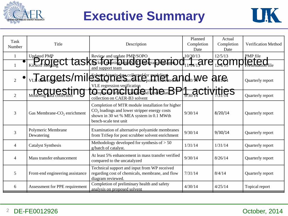
Task
NumberTitle Description
Planned
Completion
Date
Actual
Completion
Date
Verification Method
1 Updated PMP Review and update PMP/SOPO 10/30/13 12/5/13 PMP file
1 Kickoff MeetingKickoff meeting with NETL program managers
and support team 11/14/13 12/4/13 Presentation file
2 VLE data collection
Solvent kinetic data collected for modeling
including: no less than 30 data points collected for
VLE regression verification
6/30/14 5/31/14 Quarterly report
2 Modeling data collection Completion of mass transfer and kinetic data
collection on CAER-B3 solvent9/30/14 7/31/14 Quarterly report
3 Gas Membrane-CO2 enrichment
Completion of MTR module installation for higher
CO2 loadings and lower stripper energy costs
shown in 30 wt % MEA system in 0.1 MWth
bench-scale test unit
9/30/14 8/20/14 Quarterly report
3Polymeric Membrane
Dewatering
Examination of alternative polyamide membranes
from TriSep for post scrubber solvent enrichment9/30/14 9/30/14 Quarterly report
4 Catalyst SynthesisMethodology developed for synthesis of > 50
g/batch of catalyst.1/31/14 1/31/14 Quarterly report
4 Mass transfer enhancementAt least 5% enhancement in mass transfer verified
compared to the uncatalyzed9/30/14 8/26/14 Quarterly report
5 Front-end engineering assistance
Technical support and input from WP received
regarding cost of chemicals, membrane, and flow
diagram reviewed.
7/31/14 8/4/14 Quarterly report
6 Assessment for PPE requirementCompletion of preliminary health and safety
analysis on proposed solvent4/30/14 4/25/14 Topical report
• Project tasks for budget period 1 are completed
• Targets/milestones are met and we are
requesting to conclude the BP1 activities
2

Lessons Learned
• The impact of catalyst impurity could be significant –
the foaming issue
• There is need to further understand the role of catalyst
in primary amine-based solvent which we will work on
further in BP 2 at no additional cost to DOE
• The parameters for synthesis of an effective zeolite
membrane layer are sensitive for optimization. Small
synthesis changes produce large performance
variance.
DE-FE0012926 October, 20143

Project Overview
• Project management
• Catalytic solvent testing
• ASPEN modeling
• Membrane synthesis
• Cost-share
• Technical support
• PPE recommendation
• EH&S analysis
• Front-end engineering
• Techno-Economic
Evaluation
CMRG
Project Details
• Benefit from multiple CAER technologies:
solvent; catalyst, membrane, process
• Project cost:
• DOE share:$2.97M
• Cost share:$742K ($500K from CMRG)
• Period performance: 10/1/2013 – 9/30/2016
Project Objectives
• Develop a low-cost CO2 capture system
via integration of multiple CAER
technologies to verify an advanced catalytic
solvent with integrated membrane
dewatering for solvent enrichment in our
0.1MW pilot plant (Proof of concept)
DE-FE0012926 October, 20144

Anticipated Benefits
20% Dewatering, 22%
Higher Cyclic
Capacity - 20%
stripper including
reboiler
Low Liquid Recirculation:
- 20% BOP20% Reduction in
Absorber Volume:
- 9.5% Capital
Savings
DE-FE0012926 October, 20145

pilot ~0.7MW ~20 MWFundamental
Development of
concept by CAER
• Solvent Optimization
• Milestone: VLE and model
regression
• Membrane Enrichment
• Milestone: 5% enrichment over 5hr
• Catalyst Scale-up
• Milestone: Develop method to
produce 50g/batch
•Milestone: PPE recommendation &
front-end engineering analysis
Laboratory Validation and Scale-up
Parametric Testing on 0.1
MWth Unit
Overall Schedule and Milestones
Previous work Current Project Future Development
Yr 2011-2013 2013 2014 2015 2016 2017-2020 >2020
BP - 1 1/2 2/3 3 - -
Verification Testing on 0.1 MWth
Unit
• Verification Run
• Milestone: 500hr verification run
• Membrane Enrichment
• Milestone: Unit integrated and
20% dewatering observed
• Techno-Economic Analysis
• Milestone: Favorable TEA
• EH&S
• Milestone: Favorable EHS
assessment
• Catalyst Production
• Milestone: 500g produced
• Parametric Testing
• Milestone: 100hr runs with and
without catalyst completed
• Membrane Enrichment
• Milestone: 10% enrichment over
100hr and module design
DE-FE0012926 October, 20146
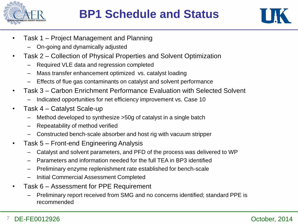
BP1 Schedule and Status
• Task 1 – Project Management and Planning
– On-going and dynamically adjusted
• Task 2 – Collection of Physical Properties and Solvent Optimization
– Required VLE data and regression completed
– Mass transfer enhancement optimized vs. catalyst loading
– Effects of flue gas contaminants on catalyst and solvent performance
• Task 3 – Carbon Enrichment Performance Evaluation with Selected Solvent
– Indicated opportunities for net efficiency improvement vs. Case 10
• Task 4 – Catalyst Scale-up
– Method developed to synthesize >50g of catalyst in a single batch
– Repeatability of method verified
– Constructed bench-scale absorber and host rig with vacuum stripper
• Task 5 – Front-end Engineering Analysis
– Catalyst and solvent parameters, and PFD of the process was delivered to WP
– Parameters and information needed for the full TEA in BP3 identified
– Preliminary enzyme replenishment rate established for bench-scale
– Initial Commercial Assessment Completed
• Task 6 – Assessment for PPE Requirement
– Preliminary report received from SMG and no concerns identified; standard PPE is
recommended
DE-FE0012926 October, 20147

Task 2. Collection of Physical
Properties and Solvent Optimization
• Pressure range of 0-350 kPa (0.03%
linearity)
• Temperature control of ±0.1 °C
• Small sample size (~1 ml)
• Full automation setup
DE-FE0012926 October, 20148

CAER-B3 VLE and Thermodynamic
Regression Results
0.1
1
10
100
1000
0 0.2 0.4 0.6 0.8
CO
2P
arti
al P
ress
ure
(kP
a)
Carbon Loading (mol of CO2/mole of alkalinity)
60C80C
100C
120C
40C
30 wt% MEA (40C)
DE-FE0012926 October, 20149

Catalyst Selection/Development
DE-FE0012926 October, 201410
• Catalyst enhancement is
improving relative to MEA
baseline (zero enhancement)

Wetted-wall Setup
CO2
N2
Liquid
Heater
Gas Saturator
WWC
P
T
CO2 Analyzer
T
Sampling
Pump
Reservoir
• Well-defined surface area for accurate
mass transfer coefficient measurement
• Simulated flue gas conditions in
scrubber (40 °C, 2% - 14% CO2 conc.)
DE-FE0012926 October, 201411

Mass Transfer Enhancement
• 10% improvement from baseline solvent to the catalyzed CAER-B3 at 0.35 C/alk.
0
0.0005
0.001
0.0015
0.002
0.0025
0.003
0.1 0.2 0.3 0.4 0.5 0.6
KG
(mo
l/(m
2·s
·kP
a))
CO2 loading (mol. CO2 captured/ mol alkalinity)
CAER-B3 with 2.3g/L C5c batch varied
CAER-B3 baseline
DE-FE0012926 October, 201412

Oxidative Degradation Experimental
Setup
• Test condition: 80 °C, 12% CO2
balanced with air
• Test time: ~200 hr
• Ion Chromatography System (IC)
for amine loss determination
DE-FE0012926 October, 201413

Degradation
Solvent Overall amine
loss (%)CAER B3 + C5c oxidative, 80°C, 288 h 13.2CAER B3 + C5z oxidative, 80°C, 288 h 7
MEA oxidative, 80°C, 288 h 11.6
CAER B3 + C5c thermal,145°C,1week 18.8MEA thermal,145°C,1week 20.3
• C5c selected for better catalytic performance than C5z
• Oxidative results show similar percent loss as MEA
• Less thermal degradation
DE-FE0012926 October, 201414

Evaluation Method for Flue Gas
Impurity Effects
• pH drop method for quick mass
transfer evaluation
• NOx and SOx are simulated by
NaNO2, NaNO3 and Na2SO4
14% CO2
MFC
>
>>
pH meter
DE-FE0012926 October, 201415

NOx and SOx Effects
• Minor effect from NOx and SOx
species
• C5c shows nitrite sensitivity
• Testing at concentrations of
1000 ppm of NOx or SOx
DE-FE0012926 October, 201416

Task 3. Solvent Enrichment
3.1: Zeolite Solvent Enrichment
Dip coating process
Dip coating for seeding process
Polishing process
Seed slurry preparation
Characterization
Blank mullite supports
XRD/SEM
Gel preparation
Separation Perfomance Alkalinity tests
Characterization
Hydrothermal synthesis
Characterization XRD/SEM
XRD/SEM
Uniform seed layer deposited on membrane support
DE-FE0012926 October, 201417

Characterization of Membrane Layer
CBV 10h 100C (6 sec deposition)
CBV TMAOH 10h 100C (6 sec deposition)
Inte
grat
ed In
ten
sity
(cp
s d
eg)
I
nte
nsi
ty (c
ps)
10 20 30 40 50 60 0
100
200
300
400
500
10 20 30 40 50 60 0
200
400
600
Inte
grat
ed In
tens
ity (c
ps d
eg)
2-theta (deg)
Inte
nsity
(cps
)
(Peak at ~45 degrees due to Fe sample holder)
DE-FE0012926 October, 201418
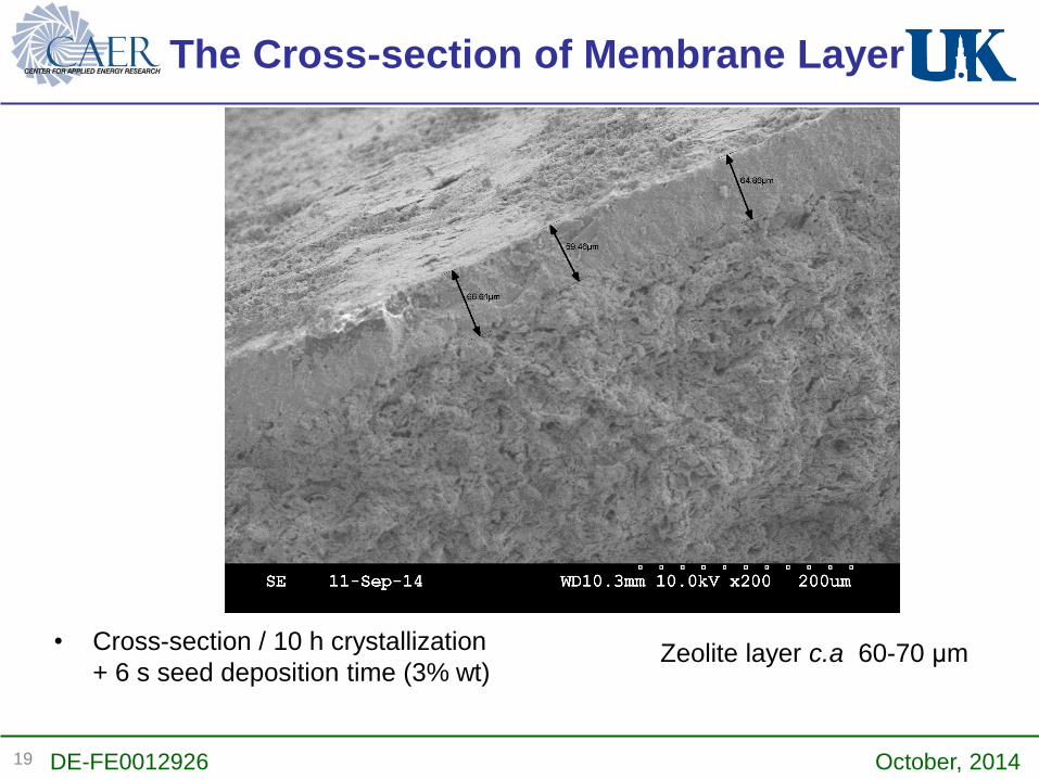
The Cross-section of Membrane Layer
Zeolite layer c.a 60-70 μm • Cross-section / 10 h crystallization
+ 6 s seed deposition time (3% wt)
DE-FE0012926 October, 201419

Evaluation setup
Zeolite membrane
Membrane reactor
DE-FE0012926 October, 2014
The initial zeolite layer is far too thick (60-70
microns) to yield sufficient flux for the
enrichment operation. It is expected a
thickness of 20-30 microns will be needed.
20

Seeding Modification yield
Improvement (1)
1.0 % seed solution /6 s deposition / 10h crystallization (100°C)
Conditions: 30% amine (0.4 carbon loaded), 100°C, 70 PSI, 30 mL/min
Time (hours) Flux (kg/(m2h) Rejection rate (%)
1.00 0.44 75.0
2.00 0.00 0.0
Zeolite layer c.a 45-50 μm Zeolite crystals
Interface Zeolite crystals and mullite
DE-FE0012926 October, 201421

1.0 % seed solution /3 s deposition / 10h crystallization (100°C)
Conditions: 30% amine (0.4 carbon loaded), 100°C, 70 PSI, 30 mL/min
Zeolite layer c.a 25 μm
DE-FE0012926 October, 2014
Seeding Modification yield
Improvement (2)
22
Vastly increased flux by using a ~25 μm vs. ~50 μm membranes

As Alternative to Zeolite Membrane
-Polymer Membrane-
• Polymer membranes acquired from a commercial vendor
including ACM2 and X20 were both examined for post
scrubber solvent enrichment. A minimum pressure of 800
psi was required.
Time / hr Pressure / psi Percent Amine Rejected
0.5 500 -
1 600 -
1.5 700 -
2 800 30.8
2.5 900 33.4
3 1000 35
3.5 1100 37
4 1200 38.6
DE-FE0012926 October, 201423

Energy Cost for Zeolite and
Polymer Membrane
• Zeolite Membrane– Pressures from 60-150
psi are necessary
– Energy cost for
pressurizing a liquid
from 20150 psi is:
0.28 kW/(ton/hr)
• Polymer Membrane– Pressures from 800-
1200 psi are necessary
– Energy cost for
pressurizing a liquid
from 201200 psi is:
2.7 kW/(ton/hr)
DE-FE0012926 October, 201424
Not pursuing the RO membrane due to
high operating pressure.

Task 3.2 Pre-absorber CO2 Enrichment
CO2 Lean
StreamMembrane
Separation
CO2 Rich
Stream
Flue Gas
Scrubbed of CO2
DE-FE0012926 October, 2014
• MTR membrane is installed and
commissioned
• Membrane concentrates CO2 to 26-
30% at permeate compared to 14%
with approximately 7% left in residual
25

Platform for Pilot Experiment
DE-FE0012926 October, 201426

Commissioning
Expt
Feed
CO2
(%)
Perm.
CO2
(%)
Residue
CO2
(%)
L/G
(wt/wt)
Stripper
bottom.
temp. (°C)
%
Capture
Energy
Btu/Ib CO2
M1 14 28 n/A 5.2 133 81 1594
M2 14 28 10 5.1 133 85 1590
Ref 14 - - 5.6 133 88 1644
Expt
Alkalinity
(mol/kg)
Lean Ldg
(mol/kg)
Rich Ldg
(mol/kg
Lean
C/N
Rich
(C/N)
M1 5.10 1.58 2.17 0.33 0.44
M2 5.10 1.49 2.18 0.29 0.44
Ref 5.64 1.74 2.14 0.33 0.42
Liquid Analysis
DE-FE0012926 October, 201427

Task 4. Catalyst Scale-up
Scale
(g)
Ligand Yield
(%)
Ligand Purity
(%)
Catalyst Yield
(%)
Catalyst Purity
(%)
1 > 90 > 90 50 > 90
5 > 90 > 90 86 > 90
20 70 > 90 77 > 90
50 > 90 > 90 81 > 90
• Large scale synthetic method of CAER
catalysts validated
• Able to produce catalyst at high purity
at scales needed for pilot testing
• Simple isolation with no purification
Collection via precipitation and filtration
DE-FE0012926 October, 201428

Task 5. Front-end Engineering
Analysis
Front-end Engineering
• Information needed for
TEA identified from WP
Catalytic Solvent Commercial
Availability
• All components are
commercially available
• Available at scale
– Mtons/yr
• Estimated catalyst cost of
~$250-350/kg
– Catalyst charge~1kg/MW
# Questions/Comments
1
Please specify the pollutant limits for the feed gas
entering the absorber (i.e. NO2, SO2, particulate,
Hg)
2
Please indicate the corrosive nature of the
solvent. For example, would 316 stainless steel be
a suitable material of construction for all
equipment and piping that is in contact with the
solvent?
3
Is there a solvent recovery column downstream of
the CO2 absorber? (As shown in Figure 1: Current
process flow description of the "Info to WP for
Task 5.docx" file)
4
Please provide a heat and material balance
around any piece of equipment that
WorleyParsons will size (e.g. columns, heat
exchanger, pumps, etc.)
DE-FE0012926 October, 201429

“… evaluation did not identify any unusual or
significant health or safety concerns that
should delay or preclude conducting this
research…”
Clayton T. Whitney, Vice President, CHMM
Sarah A. Carty, MPH
SMITH MANAGEMENT GROUP
Issued March 31, 2014
Task 6. PPE Assessment
DE-FE0012926 October, 201430

Se Removal
Precipitating Agent
• Solvent “A”:
30 wt% ethanolamine
5.0 mg/L sodium selenate
1000 mg/L sodium sulfate
pH = 10.8
Solvent “B3”:5.0 mg/L sodium selenate
1000 mg/L sodium sulfate
pH = 10.9
Achieved Se reduction to 1.43 mg/L (ppm)
DE-FE0012926 October, 201431
Ettringite

Budget and Expenditure
Budget Period 1 10/1/13 – 9/30/14
Baseline Cost PlanEstimated
Incurred Cost
Unobligated
Balance
Federal Share $888,922 $829,159 $59,763
Non-Federal Share $222,322 $207,381 $14,941
Total $1,111,244 $1,036,540 $74,704
• Down-scope of initial TEA & EHS led to BP 1 savings
• Part of savings was already applied in BP 1 to Task 3 (membrane)
• Request unobligated balance be carried to BP 3 for detailed TEA
DE-FE0012926 October, 201432
Conclusions
• Developed robust catalysts
– shown to maintain enhancement after heating at 145 °C
for 100 hr
– Negligible effect from NOx and SOx components
• VLE and regression obtained
– Data will feed into ASPEN modeling for TEA
• Membrane enrichment
– Further tune the zeolite thickness to balance the flux and
rejection rate
– Adjust the operating parameters to match with high inlet
CO2 concentration
DE-FE0012926 October, 201433

BP2 Activities
Task
NumberTitle Description
7Updated Project Management
Plan for budget period 2.Review and update PMP/SOPO
8 CAER catalyst production Production of at least 500 g of CAER catalyst
9Parametric CAER-B3
investigation
100 hour parametric study without catalyst at
bench-scale completed
10Parametric catalytic CAER-B3
investigation
100 hour parametric study with catalyst at
bench-scale completed
11 Membrane test module design Membrane test module design completed
11Membrane
dewatering/enrichment
Membrane shown to dewater CAER-B3
solvent by at least 10% over100 hours or pre
concentration achieved with 10% increased
carbon loading
• BP2 will focus on testing in our 0.1 MWth unit
• baseline testing, parametric catalytic solvent testing
• short term degradation analysis
• Membrane improvement and module design for pilot integration
DE-FE0012926 October, 201434

Budget Requested
• BP 2 budget: DOE $740,078/ cost share
$185,133
• BP 2 dates: October 1, 2014 – June 30,
2015
DE-FE0012926 October, 201435

Acknowledgements
• José Figueroa
• Lynn Brickett
• Mike Matuszewski
• project team
• Power Generation
Group
• John Moffett
• David Link
• Brandon Delis
• Talina Mathews
• Abhoyjit Bhown
• Curtis Sharp
• Clayton Whitney
• Sarah Carty
• Mike Bartone
• Vlad Vaysman
CMRG
The work presented here was made possible through funding by:
• The U.S. DOE/ National Energy Technology Laboratory
• Carbon Management Research Group: Duke Energy, EPRI, LGE&KU, DEDI, AEP
DE-FE0012926 October, 201436

Thank You!
DE-FE0012926 October, 201437