Embed Size (px)
Citation preview
Robotics and Autonomous Systems 60 (2012) 1179–1190
Contents lists available at SciVerse ScienceDirect
Robotics and Autonomous Systems
journal homepage: www.elsevier.com/locate/robot
An accurate and robust visual-compass algorithm for robot-mountedomnidirectional camerasGian Luca Mariottini a,∗, Stefano Scheggi b, Fabio Morbidi b, Domenico Prattichizzo b
a Department of Computer Science and Engineering, University of Texas at Arlington, Engineering Research Building, 500 UTA Boulevard, Arlington, TX 76019, USAb Department of Information Engineering, University of Siena, Via Roma 56, I-53100 Siena, Italy
a r t i c l e i n f o
Article history:Received 14 December 2011Received in revised form2 April 2012Accepted 7 May 2012Available online 28 May 2012
Keywords:Robot vision systemsOmnidirectional cameraVisual compassRANSAC
a b s t r a c t
Due to their wide field of view, omnidirectional cameras are becoming ubiquitous inmanymobile roboticapplications. A challenging problemconsists of using these sensors,mounted onmobile robotic platforms,as visual compasses (VCs) to provide an estimate of the rotational motion of the camera/robot from theomnidirectional video stream. Existing VC algorithms suffer from some practical limitations, since theyrequire a precise knowledge either of the camera-calibration parameters, or the 3-D geometry of theobserved scene. In this paper we present a novel multiple-view geometry constraint for paracatadioptricviews of lines in 3-D, that we use to design a VC algorithm that does not require either the knowledge ofthe camera calibration parameters, or the 3-D scene geometry. In addition, our algorithm runs in real timesince it relies on a closed-form estimate of the camera/robot rotation, and can address the image-featurecorrespondence problem. Extensive simulations and experiments with real robots have been performedto show the accuracy and robustness of the proposed method.
© 2012 Elsevier B.V. All rights reserved.
1. Introduction
1.1. Motivation and original contribution
In the last decade, we have witnessed a growing interest inautonomous robot navigation, for which the accurate estimationof the pose (i.e., orientation and translation) from sensor readings,represents a crucial issue [1–5]. Current on-board localizationsystems suffer from several limitations: for example, standardGPS cannot be used indoors because of the absence of a line ofsight to the satellite constellation. IMUs (Inertial MeasurementUnits) are used to provide an estimate of ego-motion of the robotthrough double integration of sensed accelerations; however evensmall errors will be integrated over time, thus resulting in largelocalization error over long paths.
Passive vision sensors have long been advertised as a validalternative or as a support to the above indoor-localizationsystems: in fact, cameras are inexpensive and provide a richerinformation of the surroundings than other traditional sensors(e.g., laser range finders or sonars).
In particular, paracatadioptric cameras combine a parabolicmirror (catoptric) and a refractive lens (dioptric) [6] to provide a
∗ Corresponding author. Tel.: +1 817 272 0770.E-mail addresses: [email protected] (G.L. Mariottini), [email protected]
(S. Scheggi), [email protected] (F. Morbidi), [email protected](D. Prattichizzo).
0921-8890/$ – see front matter© 2012 Elsevier B.V. All rights reserved.doi:10.1016/j.robot.2012.05.010
field of view wider than standard pinhole cameras, thus resultingin a larger number of observed features. Although these sensorshave been extensively studied in the literature [7,8], some of theirgeometric properties have yet to be fully explored, such as themulti-view constraints relating projections of 3-D lines which arecommon in many man-made environments [9].
In this paper, we are interested in exploiting such multi-view geometric constraints for robot-mounted paracatadioptriccameras, to design an efficient and robust visual compass (VC)algorithm. VCs provide an estimate of the camera/robot rotationalmotion by using only image features observed in a videosequence. Besides localization, VCs find natural application inautonomous robot motion estimation and navigation [10–17],visual servoing and homing [18,19], distributed localization ofcamera networks [20], SLAM [2], and real-time generation of 3-Dmodels using vision sensors (structure-from-motion) [21–23].
Several VC algorithms for pinhole and omnidirectional camerashave been proposed in the literature (cf., Section 1.2). However,most of them work under restrictive assumptions that limittheir applicability and performance in real scenarios. First amongthem is the assumption of known camera calibration parameters;however, incorrect knowledge of such parameters can easily leadto a biased camera-rotation estimate. Other approaches assume ana priori knowledge of some geometric properties of the 3-D scene,e.g., the correspondence of the associated image projections, orthe metric relationship in the 3-D. Finally, other methods can onlyestimate the camera rotation after a learning phase, thus requiringthe robot to perform a preliminary exploration of the environment.
1180 G.L. Mariottini et al. / Robotics and Autonomous Systems 60 (2012) 1179–1190
In this paper we present a new VC algorithm which estimatesthe camera/robot rotation angle between pairs of paracatadioptricviews. The proposed algorithm is based on new multi-viewgeometric constraints, which are valid for the projection of linefeatures, commonly found in indoor and urban environments.Moreover, our VC algorithm improves over the existing approachesin several distinctiveways: (i) the algorithmprovides a closed-formestimate of the rotation angle and it is thus suitable for a real-timeimplementation; (ii) the algorithm does not require knowledgeof image-feature correspondence; and (iii) the algorithm isuncalibrated, i.e., it does not need any preliminary camera/mirrorintrinsic calibration phase.
Given two paracatadioptric images taken by a moving cam-era/robot at two distinct locations, our VC algorithm makes jointuse of two new multi-view geometric properties to provide an ac-curate estimate of the camera/robot rotation angle by only relyingon the image projection of 3-D parallel lines. Since these image fea-tures are either circles or lines, we call these constraints disparity-circles constraint and disparity-lines constraint, respectively.We usea voting scheme to initially prune the set of candidate image fea-tures corresponding to the projection of parallel 3-D lines. A re-fined estimate of the rotation angle is then provided by means ofRANSAC over this reduced set of candidates. We performed ex-tensive simulations and indoor/outdoor real-data experiments onrobotic platforms which demonstrate that the proposed algorithmis fast, accurate, and robust to image noise and outliers.
This work is based in part on previous material presented in[24,25], compared to which we provide herein a more extendedtheory that includes the disparity-lines constraint, we design amore accurate and robust VC algorithm, and we present a moreextensive experimental validation.
1.2. Related work and organization
Several VC algorithms have been proposed in the recentrobotics literature. In [26], lines in a single pinhole view are usedto exploit the vanishing points. The camera calibration parameters,however, are assumed to be known and an initialization stageis necessary to estimate the camera orientation with respectto the scene. A correspondence-free VC algorithm has beenpresented in [27]: nevertheless, the internal camera-calibrationparameters are assumed to be known and the algorithm (at itspresent stage) is not suitable for a real-time implementation.In [28] a simultaneous localization and mapping method has beenproposed: it uses a purely-rotating hand-held low-cost calibratedcamera as a sensor and distant points as features. The featuresare initialized and deleted on-the-fly and their position is trackedusing an extendedKalman filter (EKF) bank. Because of the reducednumber of features (about a hundred), and the sequential EKFapproach employed, the method can be implemented in real-time at standard video rates. However, the underlying assumptionof features at large distances (ideally at infinity) limits theapplicability of the algorithm to vast outdoor environments.
An appearance-based VC algorithm has been presented in [29].The camera/robot compares each captured image with the previ-ous one and computes the Manhattan distance between them. Thenew image is then rotated pixel-wise in the horizontal direction inorder to find the rotation under which the distance becomes mini-mal: such rotation is provided to the robot as differential compassinformation. While the approach is conceptually simple, the algo-rithm is computationally expensive and prone to long-term drift-ing. An appearance-based method similar to [29] is used in [30] toestimate the ego-motion of a ground vehicle equipped with a cali-brated panoramic camera. However, similarly to [28], the approachappears best suited for vehicles moving over long paths in large
outdoor environments. This is also one of the features of the real-time algorithm recently proposed in [31], where the full-axis ori-entation of a camera/robot is estimated from the vanishing pointsextracted in calibrated omnidirectional images.
Finally, in [32], the images obtained from a calibrated monocu-lar camera are split into vertical sectors and a color-class transitionpattern is statistically derived by counting. The approach requiresa preliminary training phase in which the camera/robot creates an1-D cylindrical map of its surroundings by taking multiple snap-shots in different directions. In a successive localization phase,the orientation of the robot is estimated by matching the currentcolor transition pattern with the stored model, using a maximum-likelihood estimator.
The rest of the paper is organized as follows. Section 2 reviewssome basic facts about paracatadioptric projection of 3-D lines. InSection 3, the disparity-circles and disparity-lines constraints areintroduced. In Section 4, the VC algorithm is described in detail.The robustness of the proposed algorithm is shown via simulationand real-data experiments in Section 5. In Section 6, the maincontributions of the paper are summarized and possible avenuesfor future research are discussed.
2. Basics on paracatadioptric projection of 3-D lines
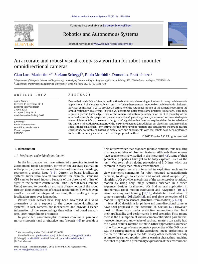
Fig. 1 illustrates the imagingmodel of a paracatadioptric camerawithmirror focus atO; a generic 3-D scene pointX ∈ R3 (expressedin the mirror frame {M}) is projected onto the parabolic mirrorsurface at x ∈ R3 through O. Then, an orthographic projectionmaps x at u (pixels), onto the image plane I. The transformationfrom X to u is analytically described by a nonlinear function η :
R3→ R2 that depends on both the camera intrinsic calibration
parameters and the mirror geometry [33,7].Let us now consider the case in which a generic 3-D line
L is observed by the paracatadioptric camera. We refer to theinterpretation plane as the plane with normal vector n =
[nx, ny, nz]T (in {M}) that passes through L and O.
Proposition 1 (Paracatadioptric Line Image [8]). Consider the setupin Fig. 1, where a line L is observed by a paracatadioptric camera at O.If nz = 0, then L projects onto the image plane I at a circle C withcenter c (pixels) given by,
c = u0 − 2 afnx
nz,ny
nz
T
,
and radius r (pixels) given by,
r =2 afnz
,
where a is the focal parameter of the parabolicmirror (i.e., the distancefrom the focus to the vertex of the paraboloid), u0 , [u0, v0]
T theoptical center (in pixels), and f (pixels) the focal length of the camera.
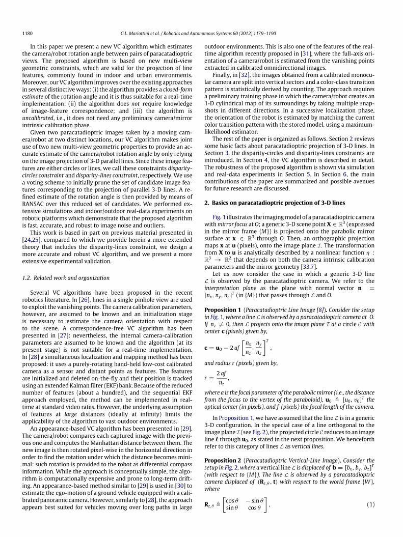
In Proposition 1, we have assumed that the line L is in a generic3-D configuration. In the special case of a line orthogonal to theimage plane I (see Fig. 2), the projected circle C reduces to an imageline ℓ through u0, as stated in the next proposition. We henceforthrefer to this category of lines L as vertical lines.
Proposition 2 (Paracatadioptric Vertical-Line Image). Consider thesetup in Fig. 2, where a vertical line L is displaced of b = [bx, by, bz]T(with respect to {M}). The line L is observed by a paracatadioptriccamera displaced of (Rz,θ , t) with respect to the world frame {W },where
Rz,θ ,
cos θ − sin θsin θ cos θ
, (1)
G.L. Mariottini et al. / Robotics and Autonomous Systems 60 (2012) 1179–1190 1181
Fig. 1. Projection of a 3-D line L. The interpretation plane passes through the focusO of the parabolic mirror and the line L, and intersects the mirror at a curve that isorthographically projected at a circle C onto the image plane I (with center c andradius r).
Fig. 2. Projection of a 3-D vertical line L. The interpretation plane intersects themirror at a curve that is orthographically projected onto the image plane at a line ℓpassing through the optical center u0 and with a slope ϕ with respect to the imagehorizontal axis.
and t , [tx, ty, tz]T . Under the previous assumptions, L projects ontothe image I at a line ℓ = [cosϕ, sinϕ]
T which passes through theoptical center u0, with slope
ϕ = arctansin θ (bx − tx) + cos θ (by − ty)cos θ (bx − tx) − sin θ (by − ty)
. (2)
Proof. See the Appendix. �
3. Multiple-view paracatadioptric line constraints
Based on the results of Proposition 1, in this section weintroduce new multi-view geometry constraints that relate theimage projections of 3-D lines on two paracatadioptric views, thecurrent and reference view, respectively. This constraint, whichwe called disparity-circles constraint, will be used in Section 4 todesign the VC algorithm for the estimation of the camera rotationangle. Our VC algorithm leverages also a second constraint, calleddisparity-lines constraint (based on the result of Proposition 2), toprovide a refined estimate of the camera rotation angle.
Without loss of generality, we henceforth assume that thereference view at O′ coincides with the world frame {W }. As aconsequence, our goal will be to estimate the rotation angle θ .
3.1. Disparity-circles constraint
The following theorem is the main result of this section:
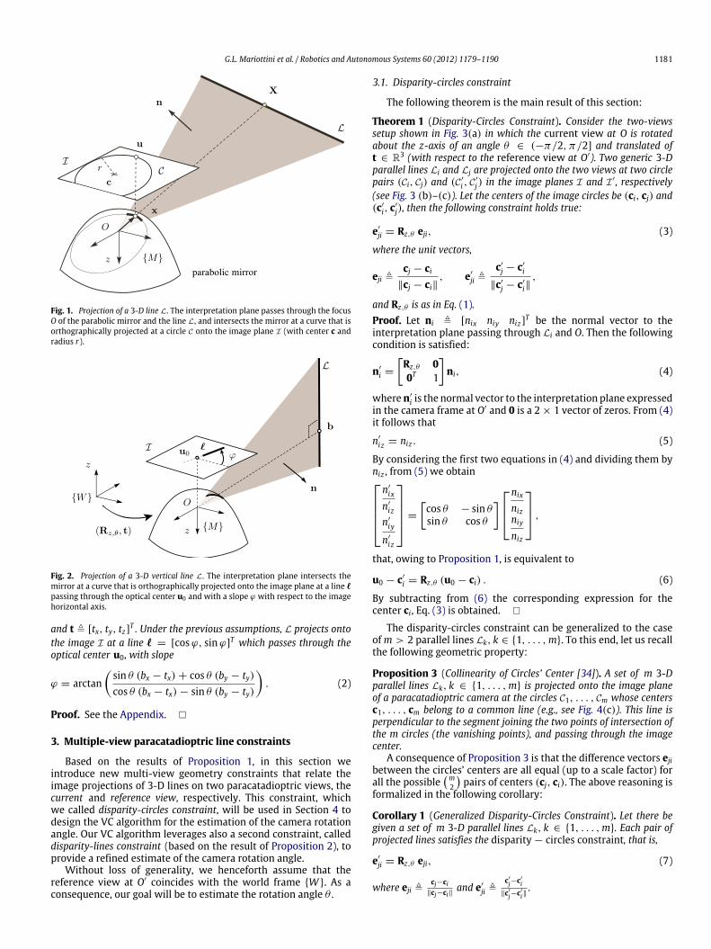
Theorem 1 (Disparity-Circles Constraint). Consider the two-viewssetup shown in Fig. 3(a) in which the current view at O is rotatedabout the z-axis of an angle θ ∈ (−π/2, π/2] and translated oft ∈ R3 (with respect to the reference view at O′). Two generic 3-Dparallel lines Li and Lj are projected onto the two views at two circlepairs (Ci, Cj) and (C′
i , C′
j) in the image planes I and I ′, respectively(see Fig. 3 (b)–(c)). Let the centers of the image circles be (ci, cj) and(c′
i, c′
j), then the following constraint holds true:
e′
ji = Rz,θ eji, (3)
where the unit vectors,
eji ,cj − ci
∥cj − ci∥, e′
ji ,c′
j − c′
i
∥c′
j − c′
i∥,
and Rz,θ is as in Eq. (1).Proof. Let ni , [nix niy niz]
T be the normal vector to theinterpretation plane passing through Li and O. Then the followingcondition is satisfied:
n′
i =
Rz,θ 00T 1
ni, (4)
wheren′
i is the normal vector to the interpretation plane expressedin the camera frame at O′ and 0 is a 2 × 1 vector of zeros. From (4)it follows that
n′
i z = niz . (5)
By considering the first two equations in (4) and dividing them byniz , from (5) we obtainn′
ix
n′
i z
n′
iy
n′
i z
=
cos θ − sin θsin θ cos θ
nix
nizniy
niz
,
that, owing to Proposition 1, is equivalent to
u0 − c′
i = Rz,θ (u0 − ci) . (6)
By subtracting from (6) the corresponding expression for thecenter ci, Eq. (3) is obtained. �
The disparity-circles constraint can be generalized to the caseofm > 2 parallel lines Lk, k ∈ {1, . . . ,m}. To this end, let us recallthe following geometric property:
Proposition 3 (Collinearity of Circles’ Center [34]). A set of m 3-Dparallel lines Lk, k ∈ {1, . . . ,m} is projected onto the image planeof a paracatadioptric camera at the circles C1, . . . , Cm whose centersc1, . . . , cm belong to a common line (e.g., see Fig. 4(c)). This line isperpendicular to the segment joining the two points of intersection ofthe m circles (the vanishing points), and passing through the imagecenter.
A consequence of Proposition 3 is that the difference vectors ejibetween the circles’ centers are all equal (up to a scale factor) forall the possible
m2
pairs of centers (cj, ci). The above reasoning is
formalized in the following corollary:
Corollary 1 (Generalized Disparity-Circles Constraint). Let there begiven a set of m 3-D parallel lines Lk, k ∈ {1, . . . ,m}. Each pair ofprojected lines satisfies the disparity − circles constraint, that is,
e′
ji = Rz,θ eji, (7)
where eji ,cj−ci
∥cj−ci∥and e′
ji ,c′j−c′i
∥c′j−c′i∥.
1182 G.L. Mariottini et al. / Robotics and Autonomous Systems 60 (2012) 1179–1190
Fig. 3. Disparity-circles constraint. (a) Two paracatadioptric cameras are displaced of (Rz,θ , t) and observe two generic 3-D parallel lines Li and Lj . (b)–(c) The two linesproject in each image plane I and I′ , at two circle pairs (Ci, Cj) and (C′
i , C′
j ), respectively. From the centers of the circles we obtain the vectors e′
ji and eji which are rotatedby an angle θ ∈ (−π/2, π/2].
It is important to note that Corollary 1 does not need thecorrespondence between lines, but it only requires the observedlines to be parallel in 3-D. This is a useful property since, giventwo catadioptric views, it is generally difficult to establish theexact correspondence between lines. Our VC algorithmwill use thedisparity-circles constraint in a voting scheme, in order to find a setof candidate parallel 3-D lines.
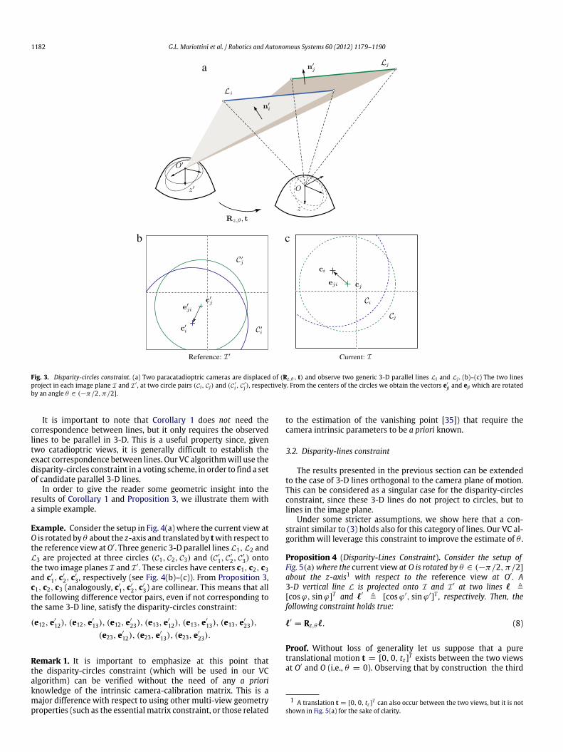
In order to give the reader some geometric insight into theresults of Corollary 1 and Proposition 3, we illustrate them witha simple example.
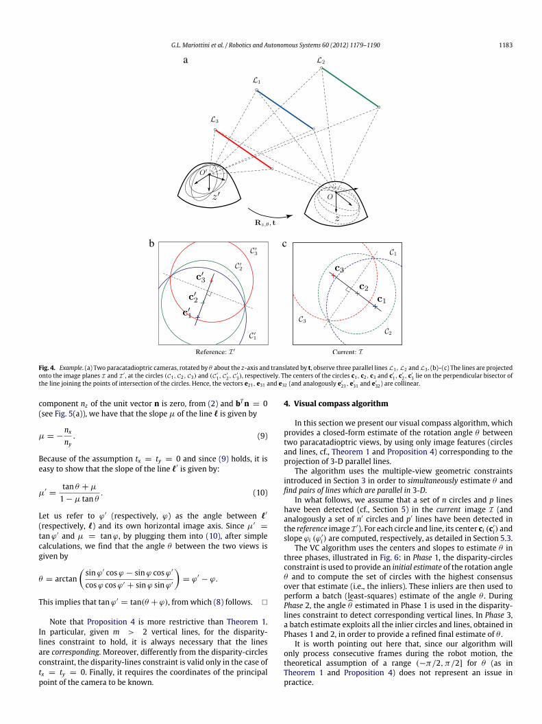
Example. Consider the setup in Fig. 4(a) where the current view atO is rotated by θ about the z-axis and translated by twith respect tothe reference view atO′. Three generic 3-D parallel lines L1, L2 andL3 are projected at three circles (C1, C2, C3) and (C′
1, C′
2, C′
3) ontothe two image planes I and I ′. These circles have centers c1, c2, c3and c′
1, c′
2, c′
3, respectively (see Fig. 4(b)–(c)). From Proposition 3,c1, c2, c3 (analogously, c′
1, c′
2, c′
3) are collinear. This means that allthe following difference vector pairs, even if not corresponding tothe same 3-D line, satisfy the disparity-circles constraint:
(e12, e′
12), (e12, e′
13), (e12, e′
23), (e13, e′
12), (e13, e′
13), (e13, e′
23),
(e23, e′
12), (e23, e′
13), (e23, e′
23).
Remark 1. It is important to emphasize at this point thatthe disparity-circles constraint (which will be used in our VCalgorithm) can be verified without the need of any a prioriknowledge of the intrinsic camera-calibration matrix. This is amajor difference with respect to using other multi-view geometryproperties (such as the essential matrix constraint, or those related
to the estimation of the vanishing point [35]) that require thecamera intrinsic parameters to be a priori known.
3.2. Disparity-lines constraint
The results presented in the previous section can be extendedto the case of 3-D lines orthogonal to the camera plane of motion.This can be considered as a singular case for the disparity-circlesconstraint, since these 3-D lines do not project to circles, but tolines in the image plane.
Under some stricter assumptions, we show here that a con-straint similar to (3) holds also for this category of lines. Our VC al-gorithm will leverage this constraint to improve the estimate of θ .
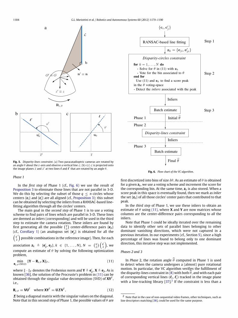
Proposition 4 (Disparity-Lines Constraint). Consider the setup ofFig. 5(a)where the current view at O is rotated by θ ∈ (−π/2, π/2]about the z-axis1 with respect to the reference view at O′. A3-D vertical line L is projected onto I and I ′ at two lines ℓ ,[cosϕ, sinϕ]
T and ℓ′ , [cosϕ′, sinϕ′]T , respectively. Then, the
following constraint holds true:
ℓ′= Rz,θℓ. (8)
Proof. Without loss of generality let us suppose that a puretranslational motion t = [0, 0, tz]T exists between the two viewsat O′ and O (i.e., θ = 0). Observing that by construction the third
1 A translation t = [0, 0, tz ]T can also occur between the two views, but it is notshown in Fig. 5(a) for the sake of clarity.
G.L. Mariottini et al. / Robotics and Autonomous Systems 60 (2012) 1179–1190 1183
Fig. 4. Example. (a) Two paracatadioptric cameras, rotated by θ about the z-axis and translated by t, observe three parallel lines L1, L2 and L3 . (b)–(c) The lines are projectedonto the image planes I and I′ , at the circles (C1, C2, C3) and (C′
1, C′
2, C′
3), respectively. The centers of the circles c1, c2, c3 and c′
1, c′
2, c′
3 lie on the perpendicular bisector ofthe line joining the points of intersection of the circles. Hence, the vectors e21, e31 and e32 (and analogously e′
21, e′
31 and e′
32) are collinear.
component nz of the unit vector n is zero, from (2) and bTn = 0(see Fig. 5(a)), we have that the slope µ of the line ℓ is given by
µ = −nx
ny. (9)
Because of the assumption tx = ty = 0 and since (9) holds, it iseasy to show that the slope of the line ℓ′ is given by:
µ′=
tan θ + µ
1 − µ tan θ. (10)
Let us refer to ϕ′ (respectively, ϕ) as the angle between ℓ′
(respectively, ℓ) and its own horizontal image axis. Since µ′=
tanϕ′ and µ = tanϕ, by plugging them into (10), after simplecalculations, we find that the angle θ between the two views isgiven by
θ = arctansinϕ′ cosϕ − sinϕ cosϕ′
cosϕ cosϕ′ + sinϕ sinϕ′
= ϕ′
− ϕ.
This implies that tanϕ′= tan(θ + ϕ), from which (8) follows. �
Note that Proposition 4 is more restrictive than Theorem 1.In particular, given m > 2 vertical lines, for the disparity-lines constraint to hold, it is always necessary that the linesare corresponding. Moreover, differently from the disparity-circlesconstraint, the disparity-lines constraint is valid only in the case oftx = ty = 0. Finally, it requires the coordinates of the principalpoint of the camera to be known.
4. Visual compass algorithm
In this section we present our visual compass algorithm, whichprovides a closed-form estimate of the rotation angle θ betweentwo paracatadioptric views, by using only image features (circlesand lines, cf., Theorem 1 and Proposition 4) corresponding to theprojection of 3-D parallel lines.
The algorithm uses the multiple-view geometric constraintsintroduced in Section 3 in order to simultaneously estimate θ andfind pairs of lines which are parallel in 3-D.
In what follows, we assume that a set of n circles and p lineshave been detected (cf., Section 5) in the current image I (andanalogously a set of n′ circles and p′ lines have been detected inthe reference image I ′). For each circle and line, its center ci (c′
i) andslope ϕi (ϕ
′
i ) are computed, respectively, as detailed in Section 5.3.The VC algorithm uses the centers and slopes to estimate θ in
three phases, illustrated in Fig. 6: in Phase 1, the disparity-circlesconstraint is used to provide an initial estimate of the rotation angleθ and to compute the set of circles with the highest consensusover that estimate (i.e., the inliers). These inliers are then used toperform a batch (least-squares) estimate of the angle θ . DuringPhase 2, the angleθ estimated in Phase 1 is used in the disparity-lines constraint to detect corresponding vertical lines. In Phase 3,a batch estimate exploits all the inlier circles and lines, obtained inPhases 1 and 2, in order to provide a refined final estimate of θ .
It is worth pointing out here that, since our algorithm willonly process consecutive frames during the robot motion, thetheoretical assumption of a range (−π/2, π/2] for θ (as inTheorem 1 and Proposition 4) does not represent an issue inpractice.
1184 G.L. Mariottini et al. / Robotics and Autonomous Systems 60 (2012) 1179–1190
Fig. 5. Disparity-lines constraint. (a) Two paracatadioptric cameras are rotated byan angle θ about the z-axis and observe a vertical line L. (b)–(c) L is projected ontothe image planes I and I′ at two lines ℓ and ℓ′ that are rotated by an angle θ .
Phase 1
In the first step of Phase 1 (cf., Fig. 6) we use the result ofProposition 3 to eliminate those lines that are not parallel in 3-D.We do this by selecting the subset of those q ≤ n circles whosecenters {ci} and {c′
i} are all aligned (cf., Proposition 3); this subsetcan be obtained by selecting the inliers from a RANSAC-based line-fitting algorithm through all the circles’ centers.
The main goal in the second step of Phase 1 is to use a votingscheme to find pairs of lines which are parallel in 3-D. These linesare deemed as inliers (corresponding) and will be used in the thirdstep to estimate the camera rotation. These inliers are found byfirst generating all the possible
q2
center-difference pairs {eji}
(cf., Corollary 1) (an analogous set {e′
ji} is obtained for all theq′
2
possible combinations in the reference image). Then, for each
association zk , {e′
ji, eji}, k ∈ {1, . . . ,N}, N = q2
q′
2
, we
compute an estimate of θ by solving the following optimizationproblem,
minRz,θ ∈SO(2)
∥Y − Rz,θ X∥F , (11)
where ∥ · ∥F denotes the Frobenius norm and Y , e′
ji,X , eji. As isknown [36], the solution of the Procruste’s problem in (11) can beobtained through the singular value decomposition (SVD) of XYT ,i.e.,
Rz,θ = VUT where XYT= UΣVT , (12)
Σ being a diagonalmatrixwith the singular values on the diagonal.Note that in this second step of Phase 1, the possible values of θ are
Fig. 6. Flow chart of the VC algorithm.
first discretized into bins of size δθ . As an estimate of θ is obtainedfor a given zk, we use a voting scheme and increment the score forthe corresponding bin. At the same time, zk is also stored. When ascore peak in this space is eventually found, then we mark as inlierthe set {zk} of all those circles’ center pairs that contributed to thatpeak.
In the third step of Phase 1, we use these inliers to obtain anestimate of θ using (11), where X and Y are now matrices whosecolumns are the center-difference pairs corresponding to all theinliers.
Note that Phase 1 could be ideally iterated over the remainingdata to identify other sets of parallel lines belonging to otherdominant vanishing directions, which were not captured in aprevious iteration. In our experiments (cf., Section 5), since a highpercentage of lines was found to belong only to one dominantdirection, this iterative step was not implemented.
Phases 2 and 3
In Phase 2, the rotation angle θ computed in Phase 1 is usedto detect when the camera undergoes a (almost) pure rotationalmotion. In particular, the VC algorithm verifies the fulfillment ofthe disparity-lines constraint in (8) with bothθ , andwith each pairof corresponding vertical lines (ℓi, ℓ
′
i) tracked in the image planewith a line-tracking library [37].2 If the constraint is less than a
2 Note that in the case of non-sequential video frames, other techniques, such asline descriptors matching [38], could be used for the same purpose.
G.L. Mariottini et al. / Robotics and Autonomous Systems 60 (2012) 1179–1190 1185
threshold τ for more than 80% of the total number of lines, thenthese are added as column vectors to the matrices X and Y in (11).These updated matrices are then used in Phase 3 to finally return abatch estimate of θ .
Remarks
We conclude this section with some remarks on the mainfeatures of our VC algorithm.
• The proposed algorithm is uncalibrated in the sense that it doesnot require any prior knowledge about the internal cameracalibration parameters (i.e., both lens and mirror parameters).
• Thanks to our multi-view geometric constraints, the VC algo-rithm is correspondence-free, in the sense that it automaticallydetects the lines that are parallel in 3-D.
• A (theoretical) minimum of two 3-D parallel lines is sufficientto compute an initial estimate of the angle θ . Note thatthe existence of parallel lines is a reasonable assumption inmany man-made environments (e.g., buildings, streets, rooms,corridors): obviously, in practice, more than two parallel linesare needed to obtain a robust estimate of θ .
• The algorithm makes use of the disparity-circles and disparity-lines constraints introduced in Section 3 and it provides aclosed-form estimate (through SVD) of the camera rotationangle. This makes the algorithm computationally efficient andsuited for real-time implementation (see the experimentalresults in Section 5). The use of RANSAC brings robustness withrespect to possible outliers.
• Phase 2 of the VC algorithm automatically detects when no (orvery small) translational displacement occurs between the twoparacatadioptric views: vertical lines can then be added to theoptimization problem in (11), thus improving the final estimateof the camera rotation angle.
5. Experimental validation
In order to test the accuracy and robustness of the proposedVC algorithm, we conducted extensive numerical simulations (seeSection 5.1) and experimental tests (see Sections 5.2–5.4).
5.1. Simulation results
The simulation results reported in this section have been ob-tained using the Epipolar Geometry Toolbox (EGT) for MATLAB [39].For the sake of generality, we implemented the unified panoramic-camera imagingmodel by Geyer and Daniilidis [7] which describesany central panoramic camera projection as a projection betweena sphere and a plane.
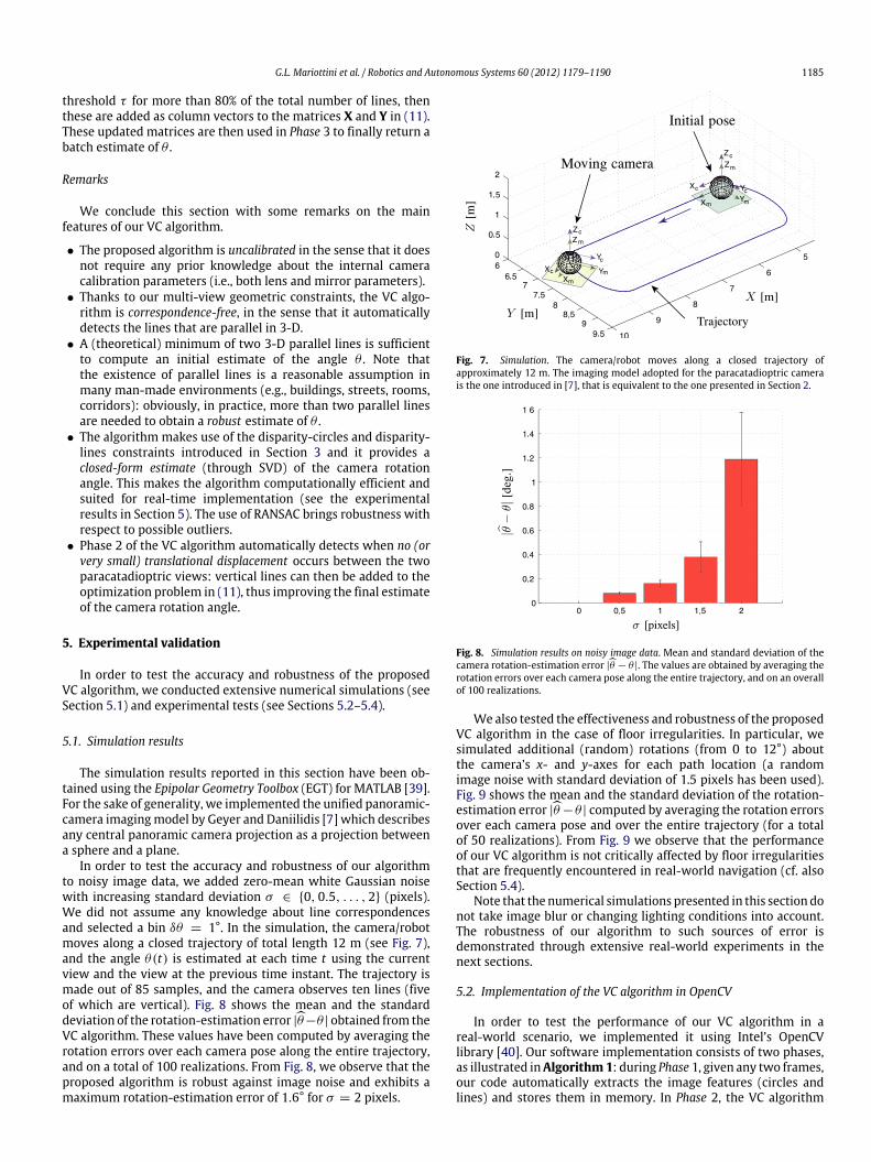
In order to test the accuracy and robustness of our algorithmto noisy image data, we added zero-mean white Gaussian noisewith increasing standard deviation σ ∈ {0, 0.5, . . . , 2} (pixels).We did not assume any knowledge about line correspondencesand selected a bin δθ = 1°. In the simulation, the camera/robotmoves along a closed trajectory of total length 12 m (see Fig. 7),and the angle θ(t) is estimated at each time t using the currentview and the view at the previous time instant. The trajectory ismade out of 85 samples, and the camera observes ten lines (fiveof which are vertical). Fig. 8 shows the mean and the standarddeviation of the rotation-estimation error |θ−θ | obtained from theVC algorithm. These values have been computed by averaging therotation errors over each camera pose along the entire trajectory,and on a total of 100 realizations. From Fig. 8, we observe that theproposed algorithm is robust against image noise and exhibits amaximum rotation-estimation error of 1.6° for σ = 2 pixels.
Fig. 7. Simulation. The camera/robot moves along a closed trajectory ofapproximately 12 m. The imaging model adopted for the paracatadioptric camerais the one introduced in [7], that is equivalent to the one presented in Section 2.
Fig. 8. Simulation results on noisy image data. Mean and standard deviation of thecamera rotation-estimation error |θ − θ |. The values are obtained by averaging therotation errors over each camera pose along the entire trajectory, and on an overallof 100 realizations.
Wealso tested the effectiveness and robustness of the proposedVC algorithm in the case of floor irregularities. In particular, wesimulated additional (random) rotations (from 0 to 12°) aboutthe camera’s x- and y-axes for each path location (a randomimage noise with standard deviation of 1.5 pixels has been used).Fig. 9 shows the mean and the standard deviation of the rotation-estimation error |θ −θ | computed by averaging the rotation errorsover each camera pose and over the entire trajectory (for a totalof 50 realizations). From Fig. 9 we observe that the performanceof our VC algorithm is not critically affected by floor irregularitiesthat are frequently encountered in real-world navigation (cf. alsoSection 5.4).
Note that the numerical simulations presented in this sectiondonot take image blur or changing lighting conditions into account.The robustness of our algorithm to such sources of error isdemonstrated through extensive real-world experiments in thenext sections.
5.2. Implementation of the VC algorithm in OpenCV
In order to test the performance of our VC algorithm in areal-world scenario, we implemented it using Intel’s OpenCVlibrary [40]. Our software implementation consists of two phases,as illustrated inAlgorithm1: during Phase 1, given any two frames,our code automatically extracts the image features (circles andlines) and stores them in memory. In Phase 2, the VC algorithm
1186 G.L. Mariottini et al. / Robotics and Autonomous Systems 60 (2012) 1179–1190
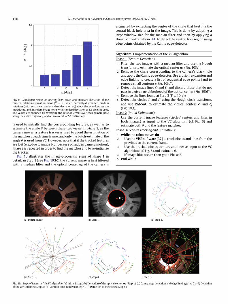
Fig. 9. Simulation results on uneven floor. Mean and standard deviation of thecamera rotation-estimation error |θ − θ | when normally-distributed randomrotations (with zero mean and standard deviation σu) about the x- and y-axes areintroduced, and a random image noise with standard deviation of 1.5 pixels is used.The values are obtained by averaging the rotation errors over each camera posealong the entire trajectory, and on an overall of 50 realizations.
is used to initially find the corresponding features, as well as toestimate the angle θ between these two views. In Phase 3, as thecamera moves, a feature tracker is used to avoid the estimation ofthematches at each time frame, and only the batch-estimate of theangle θ is used from VC. However, note that if the tracked featuresare lost (e.g., due to image blur because of sudden camera motion),Phase 2 is repeated in order to find the matches and to re-initializethe tracker.
Fig. 10 illustrates the image-processing steps of Phase 1 indetail: in Step 1 (see Fig. 10(b)) the current image is first filteredwith a median filter and the optical center u0 of the camera is
estimated by extracting the center of the circle that best fits thecentral black-hole area in the image. This is done by adopting alarge window size for the median filter and then by applying aHough circle-transform [41] to detect the central hole region usingedge points obtained by the Canny edge-detector.
Algorithm 1 Implementation of the VC algorithmPhase 1 (Feature Detection):1: Filter the two images with a median filter and use the Hough
transform to estimate the optical center u0 (Fig. 10(b)).2: Remove the circle corresponding to the camera’s black hole
and apply the Canny edge-detector. Use erosion, expansion andedge linking to create a list of sequential edge points (and toremove small contours) (Fig. 10(c)).
3: Detect the image lines ℓi and ℓ′
j and discard those that do notpass in a given neighborhood of the optical center (Fig. 10(d)).
4: Remove the lines found at Step 3 (Fig. 10(e)).5: Detect the circles Ci and C′
j using the Hough circle-transform,and use RANSAC to estimate the circles’ centers ci and c′
j(Fig. 10(f)).
Phase 2 (Initial Estimation):1: Use the current image features (circles’ centers and lines in
both images) as input to the VC algorithm (cf. Fig. 6) andestimate both θ and the feature matches.
Phase 3 (Feature Tracking and Estimation):1: while the robot moves do2: Use the ViSP software [37] to track circles and lines from the
previous to the current frame.3: Use the tracked circles’ centers and lines as input to the VC
algorithm (cf. Fig. 6) and estimate θ .4: if image blur occurs then go to Phase 2.5: end while
(a) Initial image. (b) Step 1. (c) Step 2.
(d) Step 3. (e) Step 4. (f) Step 5.
Fig. 10. Steps of Phase 1 of the VC algorithm. (a) Initial image. (b) Detection of the optical center u0 (Step 1). (c) Canny edge detection and edge linking (Step 2). (d) Detectionof the vertical lines (Step 3). (e) Contour lines removal (Step 4). (f) Detection of the circles (Step 5).
G.L. Mariottini et al. / Robotics and Autonomous Systems 60 (2012) 1179–1190 1187
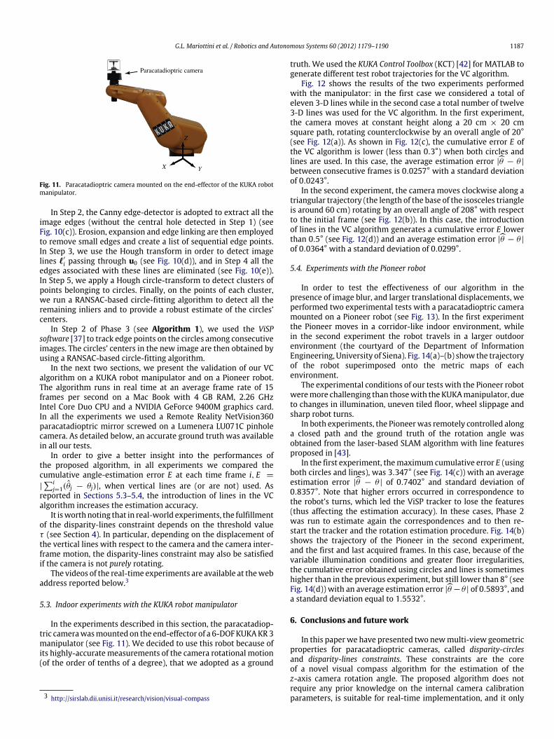
Fig. 11. Paracatadioptric camera mounted on the end-effector of the KUKA robotmanipulator.
In Step 2, the Canny edge-detector is adopted to extract all theimage edges (without the central hole detected in Step 1) (seeFig. 10(c)). Erosion, expansion and edge linking are then employedto remove small edges and create a list of sequential edge points.In Step 3, we use the Hough transform in order to detect imagelines ℓ′
i passing through u0 (see Fig. 10(d)), and in Step 4 all theedges associated with these lines are eliminated (see Fig. 10(e)).In Step 5, we apply a Hough circle-transform to detect clusters ofpoints belonging to circles. Finally, on the points of each cluster,we run a RANSAC-based circle-fitting algorithm to detect all theremaining inliers and to provide a robust estimate of the circles’centers.
In Step 2 of Phase 3 (see Algorithm 1), we used the ViSPsoftware [37] to track edge points on the circles among consecutiveimages. The circles’ centers in the new image are then obtained byusing a RANSAC-based circle-fitting algorithm.
In the next two sections, we present the validation of our VCalgorithm on a KUKA robot manipulator and on a Pioneer robot.The algorithm runs in real time at an average frame rate of 15frames per second on a Mac Book with 4 GB RAM, 2.26 GHzIntel Core Duo CPU and a NVIDIA GeForce 9400M graphics card.In all the experiments we used a Remote Reality NetVision360paracatadioptric mirror screwed on a Lumenera LU071C pinholecamera. As detailed below, an accurate ground truth was availablein all our tests.
In order to give a better insight into the performances ofthe proposed algorithm, in all experiments we compared thecumulative angle-estimation error E at each time frame i, E =
|i
j=1(θj − θj)|, when vertical lines are (or are not) used. Asreported in Sections 5.3–5.4, the introduction of lines in the VCalgorithm increases the estimation accuracy.
It isworthnoting that in real-world experiments, the fulfillmentof the disparity-lines constraint depends on the threshold valueτ (see Section 4). In particular, depending on the displacement ofthe vertical lines with respect to the camera and the camera inter-frame motion, the disparity-lines constraint may also be satisfiedif the camera is not purely rotating.
The videos of the real-time experiments are available at thewebaddress reported below.3
5.3. Indoor experiments with the KUKA robot manipulator
In the experiments described in this section, the paracatadiop-tric camerawasmounted on the end-effector of a 6-DOFKUKAKR3manipulator (see Fig. 11). We decided to use this robot because ofits highly-accuratemeasurements of the camera rotational motion(of the order of tenths of a degree), that we adopted as a ground
3 http://sirslab.dii.unisi.it/research/vision/visual-compass
truth. We used the KUKA Control Toolbox (KCT) [42] for MATLAB togenerate different test robot trajectories for the VC algorithm.
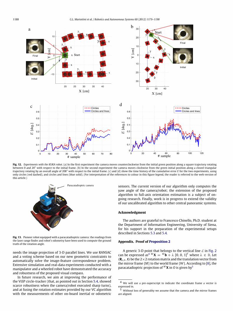
Fig. 12 shows the results of the two experiments performedwith the manipulator: in the first case we considered a total ofeleven 3-D lines while in the second case a total number of twelve3-D lines was used for the VC algorithm. In the first experiment,the camera moves at constant height along a 20 cm × 20 cmsquare path, rotating counterclockwise by an overall angle of 20°(see Fig. 12(a)). As shown in Fig. 12(c), the cumulative error E ofthe VC algorithm is lower (less than 0.3°) when both circles andlines are used. In this case, the average estimation error |θ − θ |
between consecutive frames is 0.0257° with a standard deviationof 0.0243°.
In the second experiment, the camera moves clockwise along atriangular trajectory (the length of the base of the isosceles triangleis around 60 cm) rotating by an overall angle of 208° with respectto the initial frame (see Fig. 12(b)). In this case, the introductionof lines in the VC algorithm generates a cumulative error E lowerthan 0.5° (see Fig. 12(d)) and an average estimation error |θ − θ |
of 0.0364°with a standard deviation of 0.0299°.
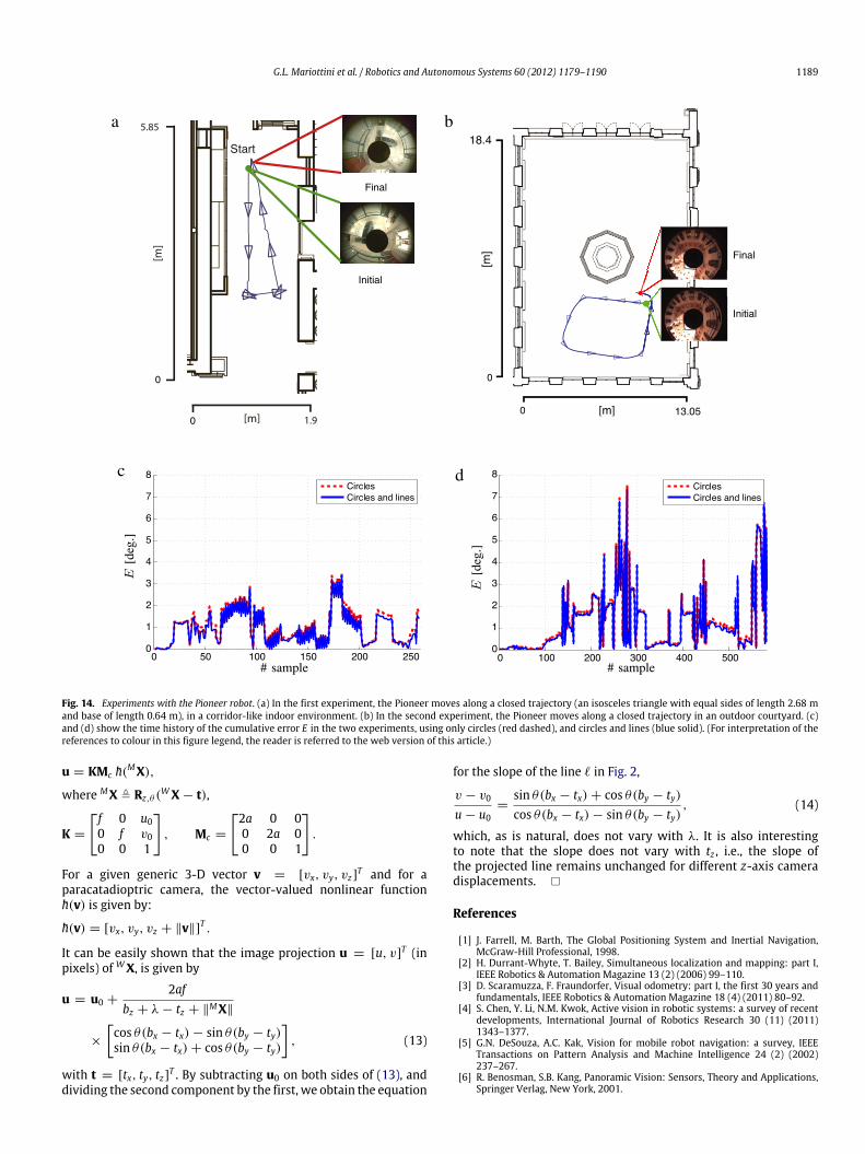
5.4. Experiments with the Pioneer robot
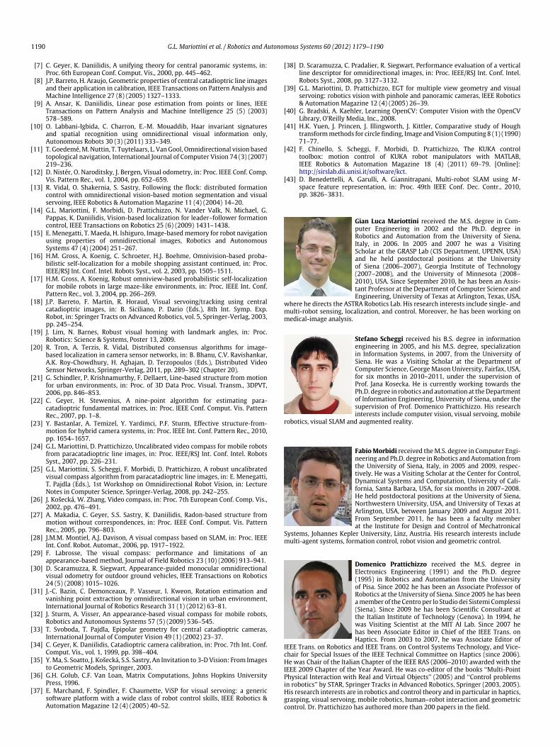
In order to test the effectiveness of our algorithm in thepresence of image blur, and larger translational displacements, weperformed two experimental tests with a paracatadioptric cameramounted on a Pioneer robot (see Fig. 13). In the first experimentthe Pioneer moves in a corridor-like indoor environment, whilein the second experiment the robot travels in a larger outdoorenvironment (the courtyard of the Department of InformationEngineering, University of Siena). Fig. 14(a)–(b) show the trajectoryof the robot superimposed onto the metric maps of eachenvironment.
The experimental conditions of our tests with the Pioneer robotweremore challenging than thosewith the KUKAmanipulator, dueto changes in illumination, uneven tiled floor, wheel slippage andsharp robot turns.
In both experiments, the Pioneerwas remotely controlled alonga closed path and the ground truth of the rotation angle wasobtained from the laser-based SLAM algorithm with line featuresproposed in [43].
In the first experiment, themaximum cumulative error E (usingboth circles and lines), was 3.347° (see Fig. 14(c)) with an averageestimation error |θ − θ | of 0.7402° and standard deviation of0.8357°. Note that higher errors occurred in correspondence tothe robot’s turns, which led the ViSP tracker to lose the features(thus affecting the estimation accuracy). In these cases, Phase 2was run to estimate again the correspondences and to then re-start the tracker and the rotation estimation procedure. Fig. 14(b)shows the trajectory of the Pioneer in the second experiment,and the first and last acquired frames. In this case, because of thevariable illumination conditions and greater floor irregularities,the cumulative error obtained using circles and lines is sometimeshigher than in the previous experiment, but still lower than 8° (seeFig. 14(d)) with an average estimation error |θ −θ | of 0.5893°, anda standard deviation equal to 1.5532°.
6. Conclusions and future work
In this paperwe have presented two newmulti-view geometricproperties for paracatadioptric cameras, called disparity-circlesand disparity-lines constraints. These constraints are the coreof a novel visual compass algorithm for the estimation of thez-axis camera rotation angle. The proposed algorithm does notrequire any prior knowledge on the internal camera calibrationparameters, is suitable for real-time implementation, and it only
1188 G.L. Mariottini et al. / Robotics and Autonomous Systems 60 (2012) 1179–1190
Final
Initial
Final
Initial
Fig. 12. Experiments with the KUKA robot. (a) In the first experiment the camera moves counterclockwise from the initial green position along a square trajectory rotatingbetween 0 and 20° with respect to the initial frame. (b) In the second experiment the camera moves clockwise from the green initial position along a closed triangulartrajectory rotating by an overall angle of 208° with respect to the initial frame. (c) and (d) show the time history of the cumulative error E for the two experiments, usingonly circles (red dashed), and circles and lines (blue solid). (For interpretation of the references to colour in this figure legend, the reader is referred to the web version ofthis article.)
Fig. 13. Pioneer robot equippedwith a paracatadioptric camera: the readings fromthe laser range finder and robot’s odometry have been used to compute the groundtruth of the rotation angle.
needs the image projection of 3-D parallel lines. We use RANSACand a voting scheme based on our new geometric constraints toautomatically solve the image-feature correspondence problem.Extensive simulation and real-data experiments conducted with amanipulator and a wheeled robot have demonstrated the accuracyand robustness of the proposed visual compass.
In future research, we aim at improving the performance ofthe ViSP circle-tracker (that, as pointed out in Section 5.4, showedscarce robustness when the camera/robot executed sharp turns),and at fusing the rotation estimates provided by our VC algorithmwith the measurements of other on-board inertial or odometric
sensors. The current version of our algorithm only computes theyaw angle of the camera/robot; the extension of the proposedalgorithm to full-axis orientation estimation is a subject of on-going research. Finally, work is in progress to extend the validityof our uncalibrated algorithm to other central panoramic systems.
Acknowledgment
The authors are grateful to Francesco Chinello, Ph.D. student atthe Department of Information Engineering, University of Siena,for his support in the preparation of the experimental setupsdescribed in Sections 5.3 and 5.4.
Appendix. Proof of Proposition 2
A generic 3-D point that belongs to the vertical line L in Fig. 2can be expressed as4 WX =
Wb + λ [0, 0, 1]T where λ ∈ R. Let(Rz,θ , t) be the 2×2 rotationmatrix and the translation vector fromthemirror frame {M} to the world frame {W }. According to [8], theparacatadioptric projection of WX in O is given by5
4 We will use a pre-superscript to indicate the coordinate frame a vector isexpressed in.5 Without loss of generality we assume that the camera and the mirror frames
are aligned.
G.L. Mariottini et al. / Robotics and Autonomous Systems 60 (2012) 1179–1190 1189
a b
c d
Fig. 14. Experiments with the Pioneer robot. (a) In the first experiment, the Pioneer moves along a closed trajectory (an isosceles triangle with equal sides of length 2.68 mand base of length 0.64 m), in a corridor-like indoor environment. (b) In the second experiment, the Pioneer moves along a closed trajectory in an outdoor courtyard. (c)and (d) show the time history of the cumulative error E in the two experiments, using only circles (red dashed), and circles and lines (blue solid). (For interpretation of thereferences to colour in this figure legend, the reader is referred to the web version of this article.)
u = KMc h(MX),
where MX , Rz,θ (WX − t),
K =
f 0 u00 f v00 0 1
, Mc =
2a 0 00 2a 00 0 1
.
For a given generic 3-D vector v = [vx, vy, vz]T and for a
paracatadioptric camera, the vector-valued nonlinear functionh(v) is given by:
h(v) = [vx, vy, vz + ∥v∥]T .
It can be easily shown that the image projection u = [u, v]T (in
pixels) of WX, is given by
u = u0 +2af
bz + λ − tz + ∥MX∥
×
cos θ(bx − tx) − sin θ(by − ty)sin θ(bx − tx) + cos θ(by − ty)
, (13)
with t = [tx, ty, tz]T . By subtracting u0 on both sides of (13), anddividing the second component by the first, we obtain the equation
for the slope of the line ℓ in Fig. 2,
v − v0
u − u0=
sin θ(bx − tx) + cos θ(by − ty)cos θ(bx − tx) − sin θ(by − ty)
, (14)
which, as is natural, does not vary with λ. It is also interestingto note that the slope does not vary with tz , i.e., the slope ofthe projected line remains unchanged for different z-axis cameradisplacements. �
References
[1] J. Farrell, M. Barth, The Global Positioning System and Inertial Navigation,McGraw-Hill Professional, 1998.
[2] H. Durrant-Whyte, T. Bailey, Simultaneous localization and mapping: part I,IEEE Robotics & Automation Magazine 13 (2) (2006) 99–110.
[3] D. Scaramuzza, F. Fraundorfer, Visual odometry: part I, the first 30 years andfundamentals, IEEE Robotics & Automation Magazine 18 (4) (2011) 80–92.
[4] S. Chen, Y. Li, N.M. Kwok, Active vision in robotic systems: a survey of recentdevelopments, International Journal of Robotics Research 30 (11) (2011)1343–1377.
[5] G.N. DeSouza, A.C. Kak, Vision for mobile robot navigation: a survey, IEEETransactions on Pattern Analysis and Machine Intelligence 24 (2) (2002)237–267.
[6] R. Benosman, S.B. Kang, Panoramic Vision: Sensors, Theory and Applications,Springer Verlag, New York, 2001.
1190 G.L. Mariottini et al. / Robotics and Autonomous Systems 60 (2012) 1179–1190
[7] C. Geyer, K. Daniilidis, A unifying theory for central panoramic systems, in:Proc. 6th European Conf. Comput. Vis., 2000, pp. 445–462.
[8] J.P. Barreto, H. Araujo, Geometric properties of central catadioptric line imagesand their application in calibration, IEEE Transactions on Pattern Analysis andMachine Intelligence 27 (8) (2005) 1327–1333.
[9] A. Ansar, K. Daniilidis, Linear pose estimation from points or lines, IEEETransactions on Pattern Analysis and Machine Intelligence 25 (5) (2003)578–589.
[10] O. Labbani-Igbida, C. Charron, E.-M. Mouaddib, Haar invariant signaturesand spatial recognition using omnidirectional visual information only,Autonomous Robots 30 (3) (2011) 333–349.
[11] T. Goedemé,M. Nuttin, T. Tuytelaars, L. VanGool, Omnidirectional vision basedtopological navigation, International Journal of Computer Vision 74 (3) (2007)219–236.
[12] D. Nistér, O. Naroditsky, J. Bergen, Visual odometry, in: Proc. IEEE Conf. Comp.Vis. Pattern Rec., vol. 1, 2004, pp. 652–659.
[13] R. Vidal, O. Shakernia, S. Sastry, Following the flock: distributed formationcontrol with omnidirectional vision-based motion segmentation and visualservoing, IEEE Robotics & Automation Magazine 11 (4) (2004) 14–20.
[14] G.L. Mariottini, F. Morbidi, D. Prattichizzo, N. Vander Valk, N. Michael, G.Pappas, K. Daniilidis, Vision-based localization for leader–follower formationcontrol, IEEE Transactions on Robotics 25 (6) (2009) 1431–1438.
[15] E. Menegatti, T. Maeda, H. Ishiguro, Image-basedmemory for robot navigationusing properties of omnidirectional images, Robotics and AutonomousSystems 47 (4) (2004) 251–267.
[16] H.M. Gross, A. Koenig, C. Schroeter, H.J. Boehme, Omnivision-based proba-bilistic self-localization for a mobile shopping assistant continued, in: Proc.IEEE/RSJ Int. Conf. Intel. Robots Syst., vol. 2, 2003, pp. 1505–1511.
[17] H.M. Gross, A. Koenig, Robust omniview-based probabilistic self-localizationfor mobile robots in large maze-like environments, in: Proc. IEEE Int. Conf.Pattern Rec., vol. 3, 2004, pp. 266–269.
[18] J.P. Barreto, F. Martin, R. Horaud, Visual servoing/tracking using centralcatadioptric images, in: B. Siciliano, P. Dario (Eds.), 8th Int. Symp. Exp.Robot, in: Springer Tracts on Advanced Robotics, vol. 5, Springer-Verlag, 2003,pp. 245–254.
[19] J. Lim, N. Barnes, Robust visual homing with landmark angles, in: Proc.Robotics: Science & Systems, Poster 13, 2009.
[20] R. Tron, A. Terzis, R. Vidal, Distributed consensus algorithms for image-based localization in camera sensor networks, in: B. Bhanu, C.V. Ravishankar,A.K. Roy-Chowdhury, H. Aghajan, D. Terzopoulos (Eds.), Distributed VideoSensor Networks, Springer-Verlag, 2011, pp. 289–302 (Chapter 20).
[21] G. Schindler, P. Krishnamurthy, F. Dellaert, Line-based structure from motionfor urban environments, in: Proc. of 3D Data Proc. Visual. Transm., 3DPVT,2006, pp. 846–853.
[22] C. Geyer, H. Stewenius, A nine-point algorithm for estimating para-catadioptric fundamental matrices, in: Proc. IEEE Conf. Comput. Vis. PatternRec., 2007, pp. 1–8.
[23] Y. Bastanlar, A. Temizel, Y. Yardimci, P.F. Sturm, Effective structure-from-motion for hybrid camera systems, in: Proc. IEEE Int. Conf. Pattern Rec., 2010,pp. 1654–1657.
[24] G.L. Mariottini, D. Prattichizzo, Uncalibrated video compass for mobile robotsfrom paracatadioptric line images, in: Proc. IEEE/RSJ Int. Conf. Intel. RobotsSyst., 2007, pp. 226–231.
[25] G.L. Mariottini, S. Scheggi, F. Morbidi, D. Prattichizzo, A robust uncalibratedvisual compass algorithm from paracatadioptric line images, in: E. Menegatti,T. Pajdla (Eds.), 1st Workshop on Omnidirectional Robot Vision, in: LectureNotes in Computer Science, Springer-Verlag, 2008, pp. 242–255.
[26] J. Košecká, W. Zhang, Video compass, in: Proc. 7th European Conf. Comp. Vis.,2002, pp. 476–491.
[27] A. Makadia, C. Geyer, S.S. Sastry, K. Daniilidis, Radon-based structure frommotion without correspondences, in: Proc. IEEE Conf. Comput. Vis. PatternRec., 2005, pp. 796–803.
[28] J.M.M. Montiel, A.J. Davison, A visual compass based on SLAM, in: Proc. IEEEInt. Conf. Robot. Automat., 2006, pp. 1917–1922.
[29] F. Labrosse, The visual compass: performance and limitations of anappearance-based method, Journal of Field Robotics 23 (10) (2006) 913–941.
[30] D. Scaramuzza, R. Siegwart, Appearance-guided monocular omnidirectionalvisual odometry for outdoor ground vehicles, IEEE Transactions on Robotics24 (5) (2008) 1015–1026.
[31] J.-C. Bazin, C. Demonceaux, P. Vasseur, I. Kweon, Rotation estimation andvanishing point extraction by omnidirectional vision in urban environment,International Journal of Robotics Research 31 (1) (2012) 63–81.
[32] J. Sturm, A. Visser, An appearance-based visual compass for mobile robots,Robotics and Autonomous Systems 57 (5) (2009) 536–545.
[33] T. Svoboda, T. Pajdla, Epipolar geometry for central catadioptric cameras,International Journal of Computer Vision 49 (1) (2002) 23–37.
[34] C. Geyer, K. Daniilidis, Catadioptric camera calibration, in: Proc. 7th Int. Conf.Comput. Vis., vol. 1, 1999, pp. 398–404.
[35] Y.Ma, S. Soatto, J. Košecká, S.S. Sastry, An Invitation to 3-DVision: From Imagesto Geometric Models, Springer, 2003.
[36] G.H. Golub, C.F. Van Loan, Matrix Computations, Johns Hopkins UniversityPress, 1996.
[37] E. Marchand, F. Spindler, F. Chaumette, ViSP for visual servoing: a genericsoftware platform with a wide class of robot control skills, IEEE Robotics &Automation Magazine 12 (4) (2005) 40–52.
[38] D. Scaramuzza, C. Pradalier, R. Siegwart, Performance evaluation of a verticalline descriptor for omnidirectional images, in: Proc. IEEE/RSJ Int. Conf. Intel.Robots Syst., 2008, pp. 3127–3132.
[39] G.L. Mariottini, D. Prattichizzo, EGT for multiple view geometry and visualservoing: robotics vision with pinhole and panoramic cameras, IEEE Robotics& Automation Magazine 12 (4) (2005) 26–39.
[40] G. Bradski, A. Kaehler, Learning OpenCV: Computer Vision with the OpenCVLibrary, O’Reilly Media, Inc., 2008.
[41] H.K. Yuen, J. Princen, J. Illingworth, J. Kittler, Comparative study of Houghtransformmethods for circle finding, Image andVision Computing 8 (1) (1990)71–77.
[42] F. Chinello, S. Scheggi, F. Morbidi, D. Prattichizzo, The KUKA controltoolbox: motion control of KUKA robot manipulators with MATLAB,IEEE Robotics & Automation Magazine 18 (4) (2011) 69–79. [Online]:http://sirslab.dii.unisi.it/software/kct.
[43] D. Benedettelli, A. Garulli, A. Giannitrapani, Multi-robot SLAM using M-space feature representation, in: Proc. 49th IEEE Conf. Dec. Contr., 2010,pp. 3826–3831.
Gian Luca Mariottini received the M.S. degree in Com-puter Engineering in 2002 and the Ph.D. degree inRobotics and Automation from the University of Siena,Italy, in 2006. In 2005 and 2007 he was a VisitingScholar at the GRASP Lab (CIS Department, UPENN, USA)and he held postdoctoral positions at the Universityof Siena (2006–2007), Georgia Institute of Technology(2007–2008), and the University of Minnesota (2008–2010), USA. Since September 2010, he has been an Assis-tant Professor at the Department of Computer Science andEngineering, University of Texas at Arlington, Texas, USA,
where he directs the ASTRA Robotics Lab. His research interests include single- andmulti-robot sensing, localization, and control. Moreover, he has been working onmedical-image analysis.
Stefano Scheggi received his B.S. degree in informationengineering in 2005, and his M.S. degree, specializationin Information Systems, in 2007, from the University ofSiena. He was a Visiting Scholar at the Department ofComputer Science, George Mason University, Fairfax, USA,for six months in 2010–2011, under the supervision ofProf. Jana Kosecka. He is currently working towards thePh.D. degree in robotics and automation at theDepartmentof Information Engineering, University of Siena, under thesupervision of Prof. Domenico Prattichizzo. His researchinterests include computer vision, visual servoing, mobile
robotics, visual SLAM and augmented reality.
FabioMorbidi received theM.S. degree in Computer Engi-neering and Ph.D. degree in Robotics and Automation fromthe University of Siena, Italy, in 2005 and 2009, respec-tively. He was a Visiting Scholar at the Center for Control,Dynamical Systems and Computation, University of Cali-fornia, Santa Barbara, USA, for six months in 2007–2008.He held postdoctoral positions at the University of Siena,Northwestern University, USA, and University of Texas atArlington, USA, between January 2009 and August 2011.From September 2011, he has been a faculty memberat the Institute for Design and Control of Mechatronical
Systems, Johannes Kepler University, Linz, Austria. His research interests includemulti-agent systems, formation control, robot vision and geometric control.
Domenico Prattichizzo received the M.S. degree inElectronics Engineering (1991) and the Ph.D. degree(1995) in Robotics and Automation from the Universityof Pisa. Since 2002 he has been an Associate Professor ofRobotics at the University of Siena. Since 2005 he has beenamember of the Centro per lo Studio dei Sistemi Complessi(Siena). Since 2009 he has been Scientific Consultant atthe Italian Institute of Technology (Genova). In 1994, hewas Visiting Scientist at the MIT AI Lab. Since 2007 hehas been Associate Editor in Chief of the IEEE Trans. onHaptics. From 2003 to 2007, he was Associate Editor of
IEEE Trans. on Robotics and IEEE Trans. on Control Systems Technology, and Vice-chair for Special Issues of the IEEE Technical Committee on Haptics (since 2006).He was Chair of the Italian Chapter of the IEEE RAS (2006–2010) awarded with theIEEE 2009 Chapter of the Year Award. He was co-editor of the books ‘‘Multi-PointPhysical Interaction with Real and Virtual Objects’’ (2005) and ‘‘Control problemsin robotics’’ by STAR, Springer Tracks in Advanced Robotics, Springer (2003, 2005).His research interests are in robotics and control theory and in particular in haptics,grasping, visual servoing, mobile robotics, human–robot interaction and geometriccontrol. Dr. Prattichizzo has authored more than 200 papers in the field.