Embed Size (px)
Citation preview
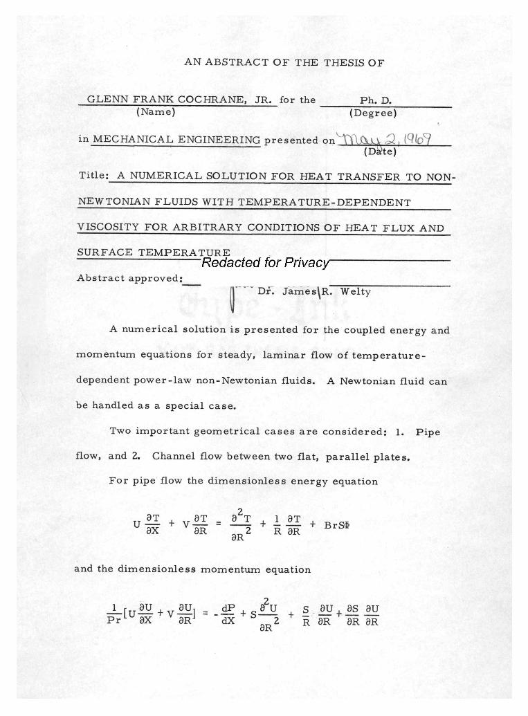
AN ABSTRACT OF THE THESIS OF
GLENN FRANK COCHRANE, JR. for the Ph. D.(Name) (Degree)
in MECHANICAL ENGINEERING presented on-A_ (q0(D te)
Title: A NUMERICAL SOLUTION FOR HEAT TRANSFER TO NON-
NEWTONIAN FLUIDS WITH TEMPERATURE-DEPENDENT
VISCOSITY FOR ARBITRARY CONDITIONS OF HEAT FLUX AND
SURFACE TEMPERATURERedacted for Privacy
Abstract approved:Dr. JameskR. Welty
A numerical solution is presented for the coupled energy and
momentum equations for steady, laminar flow of temperature-
dependent power-law non-Newtonian fluids. A Newtonian fluid can
be handled as a special case.
Two important geometrical cases are considered: 1. Pipe
flow, and 2. Channel flow between two flat, parallel plates.
For pipe flow the dimensionless energy equation
2aT + V 8T a T IaT + BrSI,aR
aR2 R aR
and the dimensionless momentum equation
1 r
8X aR8U au, _ dP c. a
2
aR
u s au 8S auPr V
' aR OR OR

are solved simultaneously; the Crank-Nicolson method is used for
writing the second partial derivatives. A digital computer is used
to solve the resulting numerical equations. For channel flow the
corresponding equations are solved with the terms involving curva-
ture deleted..
For a constitutive equation, the temperature-modified power-
lawLH
T = m(eRt Yin
is used.
Boundary conditions assumed to be known are the inlet fluid
condition and the temperature or heat flux conditions at the wall of
the conduit. The inlet temperature of the fluid is taken to be uni-
form, and the inlet velocity profile is assumed to be fully developed.
Nevertheless, the computer program which is used can be easily
modified to handle other inlet conditions. The wall temperature-
heat flux boundary condition is handled in a manner sufficiently
general to allow consideration of any arbitrarily-specified variation
in the direction of flow. For channel flow, the two plates may have
different temperature or heat flux conditions as well.
The thermal conductivity and density of the fluid are assumed
to be uniform. Buoyancy effects are neglected, but the facility for
handling viscous dissipation is included.
Computed results giving heat transfer information in the form

of Nusselt number and pressure drop as a dimensionless pressure
differential are presented for a number of heating conditions. Good
agreement is shown with available analytical solutions for some
special cases. For heating of a liquid with temperature-dependent
viscosity, the Nusselt number is shown to be greater than for a
liquid with temperature-independent viscosity, and the pressure drop
is shown to be smaller than for a liquid with no viscosity-tempera-
ture dependence. Both the heat transfer and the pressure drop ef-
fects of temperature-dependent viscosity are sufficiently large to
merit consideration in many design situations.
Complete listings of the CDC 3300 Fortran programs are in-
cluded in the Appendix.
A Numerical Solution for Heat Transfer toNon-Newtonian Fluids with Temperature-
Dependent Viscosity for ArbitraryConditions of Heat Flux and
Surface Temperature
by
Glenn Frank Cochrane, Jr.
A THESIS
submitted to
Oregon State University
in partial fulfillment ofthe requirements for the
degree of
Doctor of Philosophy
June 1969
APPROVED:
Redacted for Privacy
r of Mecham Val Engineering
in charge of major
Redacted for Privacy
Head of Department of Mechanical Engineering
Redacted for PrivacyDean of Graduate School
Date thesis is presented AAA/ 1169
Typed by Marion Palmateer for Glenn Frank Cochrane, Jr.

ACKNOWLEDGEMENTS
The help and the encouragement of the author's major
advisor Dr. James R. Welty are gratefully acknowledged. His
efforts were a direct and indispensable contribution to completion
of the research reported here.
The inspiration furnished by Dr. Ralph G. Nevins of Kansas
State University is cited as contributing to this research. Exposure
to his contagious enthusiasm during the author's early years as a
graduate student contributed indirectly but substantially to the
realization of this thesis.
Financial support and part of the computer time were
furnished through a traineeship from the National Science Founda-
tion. Additional computer time was furnished by the Oregon State
University Computer Center, D. D. Aufenkamp, Director.
NOMENCLATURE
A Area through which heat is transferred
B1, B2, B3, B4 Coefficients appearing in the finite differenceequations2nuBr kt.Brinkman number
1
Specific heat of the fluid
C, Cl, C2, C3,C4, A, B Constants in certain constitutive equations
D Pipe diameter
e Base of natural logarithms
Flux Dimensionless heat flux (Flux -_ q D for pipeA kt.
flow and Flux = q kt for channel flow)A
L
Gz Graetz number (Gz ITD pc 1
4kx 4 X/
h Convective heat transfer coefficient
DH Flow activation energy per mole
I Index in the X directionI22
Second invariant of the rate of deformation tensor
J Index in the R direction for pipe flowIndex in the Y direction for channel flow
k Thermal conductivity of the fluid
L Distance between the two parallel plates
m Constant in the power-law constitutive equation
n Exponent in the power-law constitutive equation

N Number of cells used across half the pipeNumber of cells used across the channel
Nu Nusselt number (Nu = hD for pipe flow andh(2L)
Nu for channel flow)
Nu a
Numean
Nu Ratio
Average Nusselt number based on the arithmeticmean temperature difference
Mean Nusselt number based on the log mean tem-perature difference
Ratio of Nusselt number so that for a referencesituation (shown on the same sheet) at the samevalue of x/(DRePr) for pipe flow or x/(LRe'Pr)for channel flow
O(tX2) Remainder with terms having factors of (AX)2and higher powers of OX
p Pressure
P -2pU
P.
Pr =
Q
k
Dimensionless pressure
Dimensionless pressure at the inlet
Prandtl number based on apparent viscosity
Heat transfer rate
Some unspecified variable used in explaining theCrank-Nicolson method of writing second partialderivative s
r Radial distance from the center of the pipe
R = r/D Dimensionless radius
R Gas constant
Re Reynolds number (Re 722-2- for pipe flow andTi.
Re for channel flow)
Re, p73.(2L) Reynolds number based on hydraulic diameter11. for channel flow
Dimensionless apparent viscosityi
t Temperature
t. Temperature of the fluid at the inlet
tw Wall temperature
T = t/t. Dimensionless temperature
u Velocity in the direction of bulk flow
1.7 Average velocity in the direction of bulk flow
Dimensionless velocity in the direction of bulk flowU =
71.
v Velocity perpendicular to direction of bulk flow
V = RePr
x
X
y
-Y L
Z = x/(LRe'Pr)
a, p, Y, 8,4)
11
Dimensionless velocity perpendicular to directionof bulk flow
Distance from the inlet in the direction of bulk flow
Dimensionless distance from the inlet (X DRePrx
for pipe flow and X LRePr for channel flow)
Distance perpendicular to the direction of bulk flowfor channel flow
Dimensionless distance perpendicular to directionof bulk flow for channel flow
Variables used in solving the numerical equations
Rate of shearing strain
Apparent viscosity of the fluid
P'o
T
AH 1_1 1
R t1 W
Apparent viscosity of the fluid next to the wall atthe inlet
Constant in the Arrhenius equation
Density of the fluid
Shear stress
Yield stress for a Bingham plastic
Dimensionless version of the second invariant ofthe rate of deformation tensor
D 2 12 L 22
12(t= () T for pipe flow and = (7) for
channel flow)

TABLE OF CONTENTS
Chapter
I INTRODUCTION
Page
1
Non-Newtonian Fluids--Background Information 1
Temperature Effect 4
Newtonian Fluids 5
Non-Newtonian Fluids 5
Heat Transfer to Newtonian and Non-Newtonian Fluidsfor Laminar Flow in Channels and Pipes 6
Uniform Wall Temperature or Heat Flux 7
Objective of the Present Investigation 10
II PIPE FLOW 12
Governing Equations 12Grid System and Numerical Equations 14Initial and Boundary Conditions 19Convergence 21Special Computing Features 22Results 26
III CHANNEL FLOW 49
Differences from Treatment of Pipe FlowResults
4951
IV CONCLUSIONS 61
V RECOMMENDATIONS FOR FURTHERINVESTIGATION
BIBLIOGRAPHY
APPENDICES
Appendix I Complete Topical Listing of theLiterature
Appendix II Details of the Simplification of theDifferential Equations and Conversionto Numerical Equations
62
63
67
68
Appendix III Elimination Procedures for Solving
Page
Energy and Momentum Equations 80Appendix IV Fortran Program for Pipe Flow
Problem 86Appendix V Fortran Program for Channel Flow
Problem 102Appendix VI Tabulated Results 119

LIST OF FIGURES
Figure Page
1 Cell layout,!,' 15
2 Grid system, 15
3 Simplified flow diagram 18
4 Temperature profile alteration 25
5 Nusselt numbers for pipe flow with uniform tempera-ture pipe wall - n = 1. 00 27
6 Local Nusselt number for pipe flow with uniformheat flux - n = 1. 00 29
7 Average Nusselt number for pipe flow with uniformpipe wall - n = 1. 00 31
8 Local Nusselt number for pipe flow with uniform fluxn = 0. 25, 0. 50, 0. 75, and 1. 00 33
9 Local Nusselt number for pipe flow with uniform heatflux and temperature-dependent viscosity - n = 1. 00 35
10 Pressure drop for pipe flow with uniform heat fluxand temperature-dependent viscosity - n = 1. 00. 36
11 Local Nusselt number for pipe flow with uniform heatflux and temperature-dependent viscosity - n = 1. 00 37
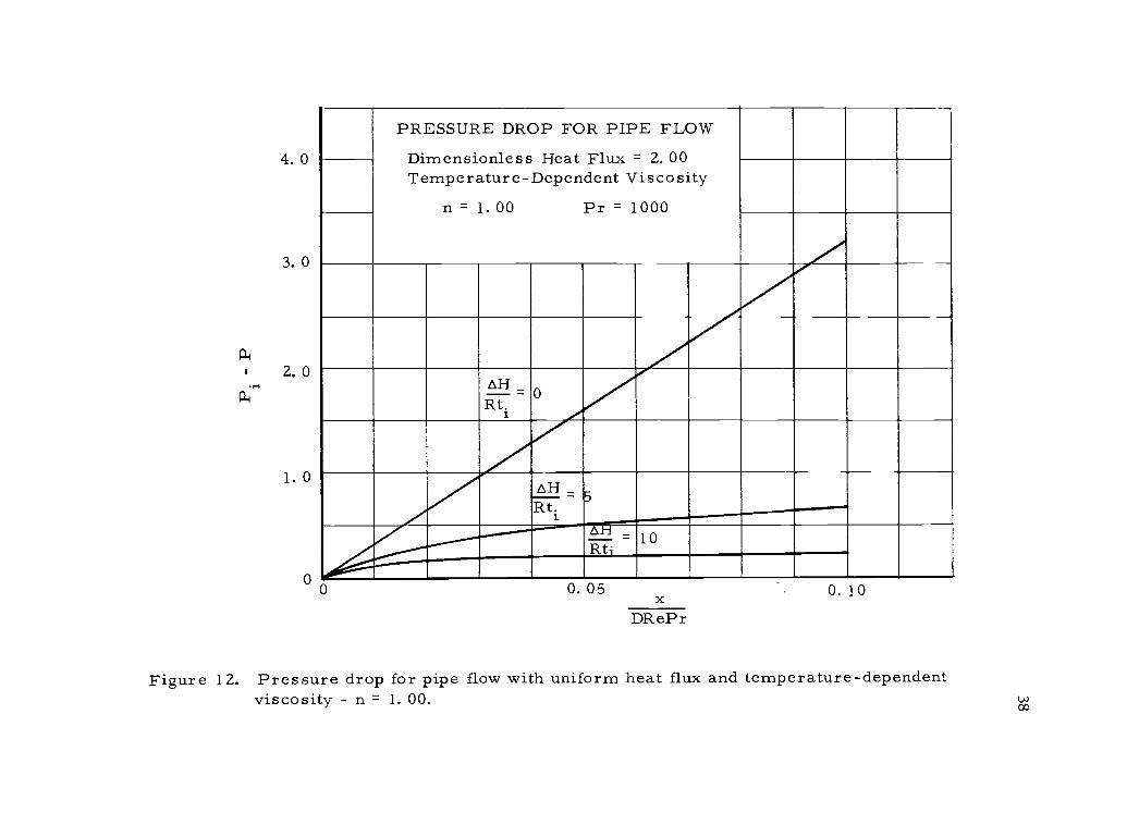
12 Pressure drop for pipe flow with uniform heat flux andtemperature-dependent viscosity - n = 1. 00 38
13 Local Nusselt number for pipe flow with uniform heatflux and temperature-dependent viscosity - n = 0. 75. 39
14 Pressure drop for pipe flow with uniform heat fluxand temperature-dependent viscosity - n = 0. 75 40
15 Local Nusselt number for pipe flow with uniform heatflux and temperature-dependent viscosity - n = 0. 50 41
16 Pressure drop for pipe flow with uniform heat fluxand temperature-dependent viscosity - n = 0. 50 42

Figure Page
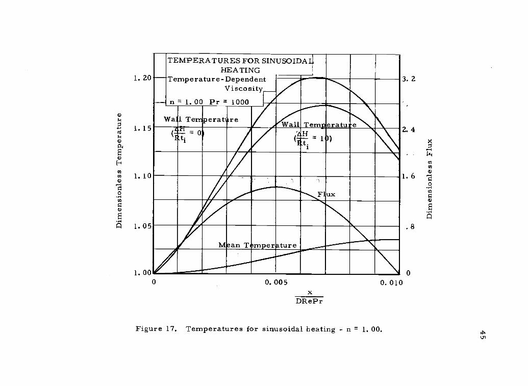
17 Temperatures for sinusoidal heating - n = 1. 00 45
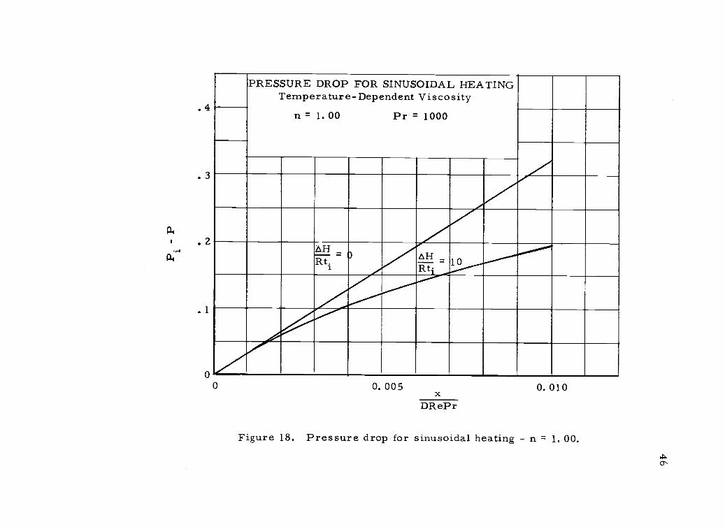
18 Pressure drop for sinusoidal heating - n = 1. 00 46
19 Temperatures for sinusoidal heating - n = 0. 50 47
20 Pressure drop for sinusoidal heating - n = 0. 50 48
21 Nusselt numbers for channel flow with uniformtemperature walls - n = 1. 00 53
22 Local Nusselt number for channel flow with uniformwall heat flux n = 0. 25, 0. 50, 0. 75, and 1. 00 55
23 Local Nusselt number for channel flow with uniformwall heat flux and temperature-dependent viscosity -n = 1. 00
24 Pressure drop for channel flow with uniform wallheat flux and temperature-dependent viscosityn = 1. 00
56
57
25 Temperatures for non-symmetrical heating - n = 1. 00 58
26 Pressure drop for non-symmetrical heating - n = 1. 00 59

A NUMERICAL SOLUTION FOR HEAT TRANSFER TONON-NEWTONIAN FLUIDS WITH TEMPERATURE-
DEPENDENT VISCOSITY FOR ARBITRARYCONDITIONS OF HEAT FLUX AND
SURFACE TEMPERATURE
I. INTRODUCTION
Non-Newtonian Fluids--Background Information
In attempting to deal analytically with a real material, a simple
mathematical model for the material's rheological properties is
desirable so long as the behavior of the material is adequately de-
scribed. For elastic solids the proportionality between stress and
strain (Hookers law) gives a simple model which is sufficiently ac-
curate for use in many engineering calculations. The corresponding
model for viscous fluids is the Newtonian model which treats shear
stress as being proportional to the rate of shearing strain (shear
rate). Again the simple model is sufficiently accurate for many
engineering calculations. However, in fluid mechanics the inade-
quacy of the simple Newtonian model soon becomes apparent. The
so-called Weissenberg effect (10, p. 230-231), where a stirred
liquid climbs the shaft of the stirring device, cannot be explained
using the Newtonian model. Neither can the "elastic water" which
flows over the edge of an upright pitcher (1) be explained from the
simple (and very useful) but often inadequate Newtonian model. De-
partures from Newtonian behavior can be much more subtle. In the
next few paragraphs a summary of the present-day engineering

classification of fluids is given. This summary follows the system
used in references (2; 40, p. 1-19; 9, p. 1-15).
Fluids may be broadly grouped as time-independent, time-
dependent, and visco-elastic.
The time-independent fluids may be further divided into four
groups called Newtonian, pseudoplastic, dilatant, and Bingham
plastic. The power law,
nT = m
2
may be used to describe Newtonian, pseudoplastic, and dilatant be-
havior; other models have been used and have some advantages for
pseudoplastic and dilatant fluids under some conditions. For a
Newtonian fluid the exponent n equals unity, and the coefficient m
is the coefficient of viscosity usually denoted by 1.1. Water, air, and
light oils are ordinarily considered as being Newtonian fluids. A
pseudoplastic fluid can be said to "thin out" at high shear rates; for
a pseudoplastic the exponent n is less than unity. The 'thinning out"
effect can be seen by defining an "apparent viscosity" based on the
Newtonian model:
T ,n-1E = my
With the exponent n positive and less than unity, the apparent
viscosity decreases with increasing shear rate. Pseudoplastic
3
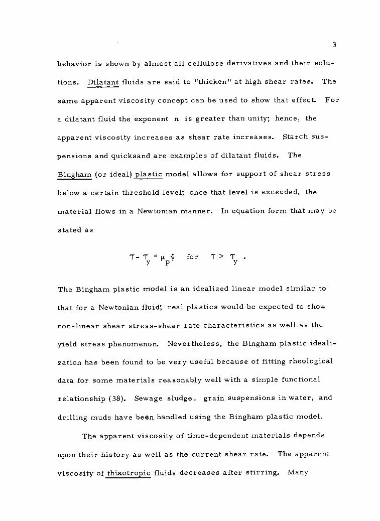
behavior is shown by almost all cellulose derivatives and their solu-
tions. Dilatant fluids are said to "thicken" at high shear rates. The
same apparent viscosity concept can be used to show that effect. For
a dilatant fluid the exponent n is greater than unity; hence, the
apparent viscosity increases as shear rate increases. Starch sus-
pensions and quicksand are examples of dilatant fluids. The
Bingham (or ideal) plastic model allows for support of shear stress
below a certain threshold level; once that level is exceeded, the
material flows in a Newtonian manner. In equation form that may be
stated as
T- T for T > T .Y P
The Bingham plastic model is an idealized linear model similar to
that for a Newtonian fluid; real plastics would be expected to show
non-linear shear stress-shear rate characteristics as well as the
yield stress phenomenon. Nevertheless, the Bingham plastic ideali-
zation has been found to be very useful because of fitting rheological
data for some materials reasonably well with a simple functional
relationship (38). Sewage sludge , grain suspensions in water, and
drilling muds have been handled using the Bingham plastic model.
The apparent viscosity of time-dependent materials depends
upon their history as well as the current shear rate. The apparent
viscosity of thixotropic fluids decreases after stirring. Many

4
industrial and most biological fluids show thixotropic behavior. A
few examples are paints, inks, mayonnaise, and milk products. The
antithesis of a thixotropic fluid is a rheopectic fluid which thickens
with stirring. Rheopectic fluids are extremely rare, but a few are
known. They are considered to be of insignificant industrial im-
portance.
As the name implies, a visco-elastic material has both viscous
and elastic properties. For discussion of mathematical models for
treating visco-elastic materials, references (11, 12, 40) are sug-
gested.
Temperature Effect
The temperature effect on the viscosity of certain fluids--both
Newtonian and non - Newtonian - -is well known and readily observed.
For liquids the viscosity is decreased by raising the temperature.
Food products such as honey, cream, and buttermilk furnish handy
evidence of the effect of temperature on viscosity. Oils, paints, and
most other heavy, thick fluids show marked changes of viscosity with
temperature. Such changes become very important when studying the
velocity distribution in situations where temperature gradients occur.
For example, with a fully developed laminar velocity profile at the
inlet of a heated pipe section, the velocity profile would be expected
to become more nearly uniform downstream from the inlet;

5
therefore, higher heat transfer rates would be expected than for fully
developed flow. In such situations some analytical means must be
used to account for the temperature effect on viscosity. Some of the
more common constitutive equations for treating materials with
temperature-dependent viscosity are given in the next few paragraphs.
Newtonian Fluids
The Arrhenius equationOHRt
is the classical model used to account for viscosity changes with
temperature for Newtonian liquids.
Other models have been used by some investigators. Pigford
(211) and Rosenberg and Hellums (34) used an empirical model
= C1
+ C t
in their investigations.
Non-Newtonian Fluids
For dealing with temperature dependent pseudoplastic ma--
terials, Christiansen, et al., (6, 7, 8) used a power law equation

6
AH
T = m(ieRt )n
with a temperature term similar to that of the Arrhenius equation.
That model is simpler than a theoretical model previously suggested
by Ree and Eyring (30)
Aoff HRtRt 1 -1 e
T e + sinh ( )
and fits rheological data adequately for most purposes (6).
Gee and Lyon (13) used an empirical temperature-dependent
constitutive equation
AFT
3
Rt / (1 + C4Tn)
in dealing with a high polymer.
Heat Transfer to Newtonian and Non-Newtonian Fluidsfor Laminar Flow in Channels and Pipes
In attempting to organize the heat transfer literature for dis-
cussion, one finds the assignment of a publication to one well defined,
specific category impossible because many publications cover several
categories. To avoid tedious repetition in the discussion below, eaci,
publication is discussed only under the category of primary emphasis.
A topical listing of the cited literature giving complete coverage is

7
included as Appendix I. Unless otherwise stated the references
cited in this discussion deal with steady, laminar flow.
Uniform Wall Temperature or Heat Flux
The classical Graetz-Nusselt problem applies to a situation
where a viscous fluid with uniform properties flows either in a
channel between two flat, parallel plates or in a pipe. The walls
are assumed to be maintained at a uniform temperature, and the fluid
is assumed to have a fully developed laminar velocity profile through-
out the heated (or cooled) section. For solution of the Graetz-
Nusselt problem the work of Sellars, Tribus, and Klein (36) is the
usually accepted standard. They solved the energy partial differ-
ential equation by separation of variables and developed a method for
evaluating the resulting constants and eigenvalues for both channel
-flow and_pipe flow. For channel flow the accepted values (2,0, p. 130)
are the ones due to Sellars, Tribus, and Klein, but for pipe flow,
the values presented by Lipkis (25) in a discussion of the Sellars,
Tribus, and Klein paper are used (20, p. 125). For uniform heat
flux replacing the uniform wall temperature boundary condition, the
same problem has been solved by Seigel, Sparrow, and Hallman (35)
for pipe flow. Once again the separation of variables technique was
used to solve the energy equation, and values are presented for the
constants and eigenvalues.

8
Dropping the fully developed velocity profile assumption in-
troduces the additional problem of solving the momentum equation for
a developing velocity profile (the hydrodynamic entry length problem).
For uniform wall temperature Kays (21) solved the combined hydro-
dynamic-thermal entry length problem for Pr . 7 using an ap-
proximate velocity profile and numerically integrating the energy
equation. Goldberg (20, p. 142) extended Kays solution for other
values of the Prandtl number. Heaton, Reynolds, and Kays (14)
present an approximate analytical solution obtained by linearizing
the energy equation. Their solutions apply for the case of uniform
heat flux for the circular-tube annulus family which includes both
pipe and channel flow. A numerical solution for combined hydro-
dynamic and thermal entry lengths in channels is presented by
Hwang (16) and Hwang and Fan (17, 18). They first solved the mo-
mentum equation assuming uniform viscosity and then used the re-
sulting velocities in solving the energy equation. Their work was
limited to situations having uniform wall temperatures.
To solve the Graetz-Nusselt problem for a non-Newtonian
liquid with temperature-independent viscosity, Lyche and Bird (26)
used a separation of variables approach similar to that used by
Sellars, Tribus, and Klein (36) for Newtonian fluids. The paper by
Lyche and Bird is devoted to fully-developed pipe flow of a power-
law pseudoplastic fluid.
9
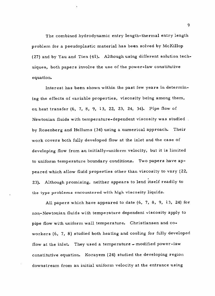
The combined hydrodynamic entry length-thermal entry length
problem for a pseudoplastic material has been solved by McKillop
(27) and by Yau and Tien (41). Although using different solution tech-
niques, both papers involve the use of the power-law constitutive
equation.
Interest has been shown within the past few years in determin-
ing the effects of variable properties, viscosity being among them,
on heat transfer (6, 7, 8, 9, 13, 22, 23, 24, 34). Pipe flow of
Newtonian fluids with temperature-dependent viscosity was studied
by Rosenberg and Hellums (34) using a numerical approach. Their
work covers both fully developed flow at the inlet and the case of
developing flow from an initially-uniform velocity, but it is limited
to uniform temperature boundary conditions. Two papers have ap-
peared which allow fluid properties other than viscosity to vary (22,
23). Although promising, neither appears to lend itself readily to
the type problems encountered with high viscosity liquids.
All papers which have appeared to date (6, 7, 8, 9, 13, 24) for
non-Newtonian fluids with temperature dependent viscosity apply to
pipe flow with uniform wall temperature. Christiansen and co-
workers (6, 7, 8) studied both heating and cooling for fully developed
flow at the inlet. They used a temperature modified power-law
constitutive equation. Korayem (24) studied the developing region
downstream from an initial uniform velocity at the entrance using

10
the same constitutive equation. Gee and Lyon (13) presented the first
study for non-Newtonian fluids with temperature-dependent viscosity
in 1957. They took into account the effects of viscous dissipation and
expansion cooling. Their analysis also allows solution with certain
transient conditions. Coupal (9) dealt with viscous dissipation as well
as the effect of temperature on viscosity.
Literature dealing with non-uniform wall temperature or heat
flux is indeed sparse. Axial variations of wall temperature or heat
flux are touched on in the paper by Sellars, Tribus, and Klein (36).
Their work is limited to fully developed Newtonian flow in pipes.
Reynolds (31, 32) deals with circumferential heat flux variations in
pipe flow for fully developed Newtonian flow, and Inman (19) deals
similarily with fully developed power-law flow. No literature exists
concerning axial variations in wall temperature or heat flux for non-
Newtonian fluid flow, nor is there any reported work which takes
viscosity changes with temperature into account for situations having
non-uniform wall temperature or heat flux.
Objective of the Present Investigation
The objective of the present investigation is the solution by
numerical means of the simultaneous energy, momentum, and con-
tinuity partial differential equations for laminar flow of non-
Newtonian fluids with temperature-dependent viscosity. The
11
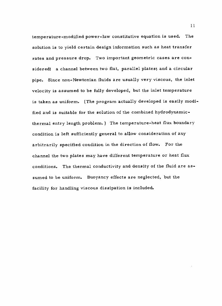
temperature-modified power-law constitutive equation is used. The
solution is to yield certain design information such as heat transfer
rates and pressure drop. Two important geometric cases are con-
sidered: a channel between two flat, parallel plates; and a circular
pipe. Since non-Newtonian fluids are usually very viscous, the inlet
velocity is assumed to be fully developed, but the inlet temperature
is taken as uniform. (The program actually developed is easily modi-
fied and is suitable for the solution of the combined hydrodynamic-
thermal entry length problem. ) The temperature-heat flux boundary
condition is left sufficiently general to allow consideration of any
arbitrarily specified condition in the direction of flow. For the
channel the two plates may have different temperature or heat flux
conditions. The thermal conductivity and density of the fluid are as-
sumed to be uniform. Buoyancy effects are neglected, but the
facility for handling viscous dissipation is included.
12
IL PIPE FLOW
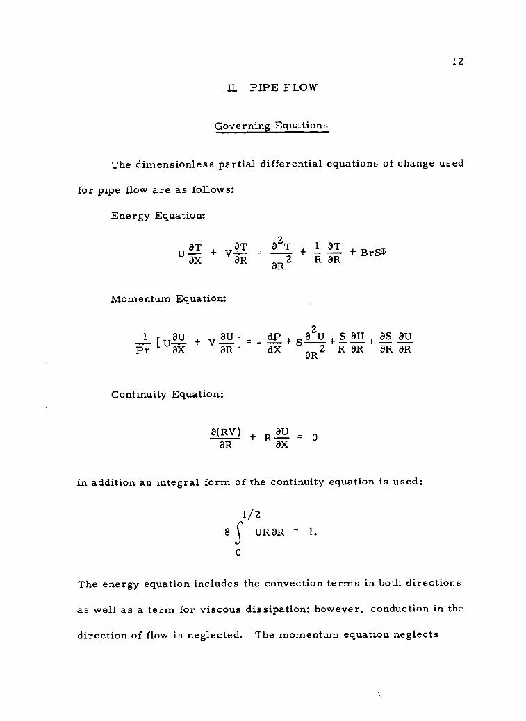
Governing Equations
The dimensionless partial differential equations of change used
for pipe flow are as follows:
Energy Equation:
8T 3T 82ax
T I OT+ VOR
= + 8R"F. BrS
OR2
Momentum Equation:
I 8U 8U dP 4. 82U S 3U 8S au[ + v = - +
ORPr 8X 8R dXOR
Continuity Equation:
8(RV) 8U =OR
In addition an integral form of the continuity equation is used:
1/28 .11 UR aR = 1.
The energy equation includes the convection terms in both directions
as well as a term for viscous dissipation; however, conduction in the
direction of flow is neglected. The momentum equation neglects

13
buoyancy effects, some secondary terms in the shear stress evalua-
tion, and any pressure variation except that in the direction of flow.
The flow is assumed to be steady and laminar. Two forms of the
continuity equation are used: the integral form, which expresses the
steady-flow assumption, and the differential form. Both equations
as stated are for incompressible flow. Each of the four equations
above is specialized in Appendix II from the appropriate starting point
suggested by Bird, Stewart, and Lightfoot (3) with each simplification
or deletion stated.
The set of simultaneous equations above includes two second-
order, parabolic partial differential equations (energy and momentum)
plus an integral equation and a first-order partial differential equa-
tion. For the situations considered in this investigation, the initial
and boundary conditions are known but the final condition is not.
Thus a marching solution is used in the direction of flow; a set of un-
known values is calculated from known conditions upstream. The
present solution may be considered as an extension of that used by
others (4, 5, 16, 17, 18, 34) in treating problems with Newtonian
fluids.
For a constitutive equation, the temperature-modified power-
law is used:OH
T me Rt n-1
14
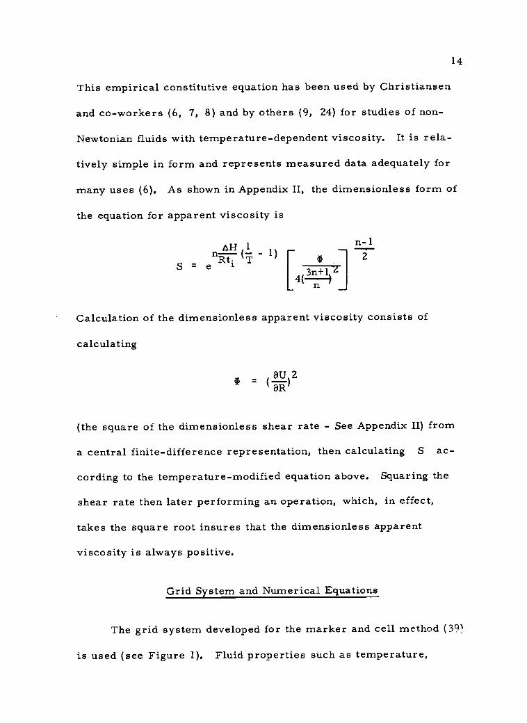
This empirical constitutive equation has been used by Christiansen
and co-workers (6, 7, 8) and by others (9, 24) for studies of non-
Newtonian fluids with temperature-dependent viscosity. It is rela-
tively simple in form and represents measured data adequately for
many uses (6). As shown in Appendix II, the dimensionless form of
the equation for apparent viscosity is
AHn (T
- 1)RtS = e
n -1
4(71[ 31111-71.-1
Calculation of the dimensionless apparent viscosity consists of
calculating
81712
(the square of the dimensionless shear rate - See Appendix II) from
a central finite-difference representation, then calculating S ac-
cording to the temperature-modified equation above. Squaring the
shear rate then later performing an operation, which, in effect,
takes the square root insures that the dimensionless apparent
viscosity is always positive.
Grid System and Numerical Equations
The grid system developed for the marker and cell method (39
is used (see Figure 1). Fluid properties such as temperature,

15
Flow
R
U(1, J)U(1-1, J)
J)
T(I, J)P(I; J)S (I, J)
V(I, J-1)
X
I --index in theX-direction
J--index in theR-direction
Figure 1. Cell layout.
1=1 I= 2 I= 3
PipeCenterline
PipeWall
XX
XX )XX )XX )
XX )
J=N
J=N-1
J=2
J=1
Figure 2. Grid system.
1E1121°-X
knownquantity
Xquantityto bedetermined
16
pressure, and apparent viscosity are defined at the center of a cell
with the velocities defined on the cell boundaries. For problems
of the type considered, the main advantage of this grid system is that
rigorous handling of the incompressible differential equation of con-
tinuity is made possible. To carry out the marching solution for
temperature, velocity, and pressure, three sets of cells are needed
(see Figure 2). All velocities or properties at locations indicated
with a dot, all variables with first index 2 or less, are assumed
to be known and those at locations indicated with X, first index equal
to 3, are unknown and must be determined. The artificial row of
cells outside the wall and the row beyond the centerline are for ap-
plication of the of the boundary conditions which is discussed later.
The details of writing the difference equations are carried out in
Appendix II.
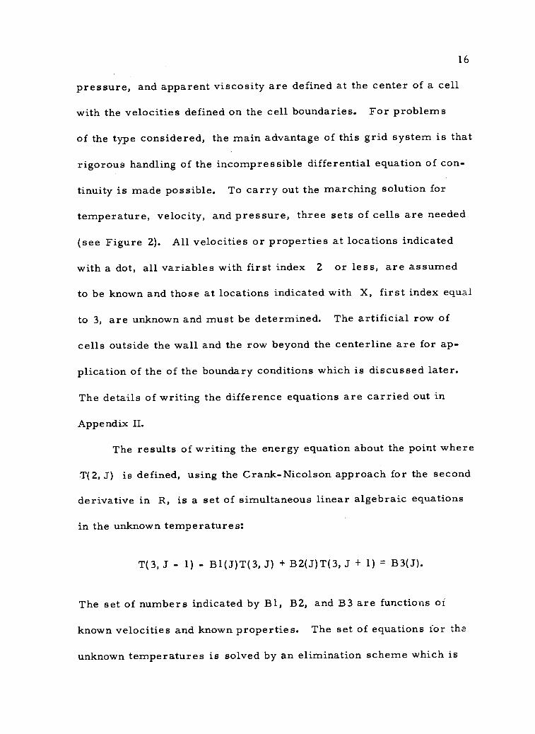
The results of writing the energy equation about the point where
T(2, J) is defined, using the Crank-Nicolson approach for the second
derivative in R, is a set of simultaneous linear algebraic equations
in the unknown temperatures:
T(3, J - 1) - Bl(J)T(3, J) + B2(J)T(3, J + 1) = B3(J).
The set of numbers indicated by Bl, B2, and B3 are functions of
known velocities and known properties. The set of equations for the
unknown temperatures is solved by an elimination scheme which is

17
given in detail in Appendix III.
Writing the momentum equation about the point where U(2, J) is
defined, again using the Crank-Nicolson representation for the second
derivative with respect to R, yields a set of simultaneous pseudo-
linear algebraic equations with velocities and pressure differential
as unknowns:
U(3, J - 1) - B1(J)U(3, J) + B2(J)U(3, J + 1) - B3(J)AP = B4(J).
The integral form of the continuity equation is written in
numerical terms using the trapezoidal rule and is appended to the
set of momentum equations to give N-1 equations with N- 2 unknown
velocities and the unknown pressure differential.
The set of equations thus formed is solved by an elimination
scheme for which the details are given in Appendix III. In this set
of equations, the numbers B1, B2, B3 and B4 are functions not only
of known velocities and known properties but are also functions of the
apparent viscosities S(3, J) which can be only estimated until the
shear rates (calculated from the velocities) are known. Thus for a
non-Newtonian fluid the equations are not actually linear, and an
iterative procedure is needed. A simplified flow diagram for the
calculation of a set of unknown values is given as Figure 3. To ob-
tain a convergence check on the iterative procedure, the momentum
equation for each cell is written as a residue.

18
CalculateTemperaturesfrom Energy
Equation
EstimateApparent
Viscosities
CalculateVelocities
andPressure Drop
fromMomentum and Continuity
Equations
RecalculateApparent Viscosities
IsMomentum
Equation SatisfiedEverywhere
Yes
Exit
Figure 3. Simplified flow diagram.

19
Initial and Boundary Conditions
The inlet (initial) conditions are assumed to be uniform tem-
perature and fully developed velocity. For a power-law fluid the
fully developed velocity profile, in dimensionless form, is given by
(40, p. 62)
3n +1n +
U n + 1 [ (2R). n
(Substitution of unity for n of course gives the familiar parabolic
velocity distribution for a Newtonian fluid. )
The velocity boundary conditions are dictated by the assump-
tions of no slip at an impervious wall and symmetry about the pipe
axis. In equation form the velocity boundary conditions are
and
U = 0 and V = 0 at the wall
U(-R) = U(+R)and V = 0 at the centerline.
For the grid system used, the application of the boundary conditions
for V is direct (see Figure 3), but since U is not defined at the
wall or the centerline, some other means must be used to apply the
boundary condition on U. For the condition at the wall the artificial
row of cells outside the wall is used; the value of U for the cell
outside is given the negative of the value of U for the first cell

20
inside the wall. Thus the arithmetic average of the two satisfies
the no slip condition, that U = 0, at the wall.
For the centerline condition the velocity in the artificial cell
beyond the centerline is given the same value as the velocity at the
first cell inside the centerline boundary. In this way the symmetry
about the centerline is preserved.
The temperature or heat-flux condition at the wall is handled
in a way which allows variation in the direction of flow by storing the
appropriate value of wall temperature or heat flux. At any pipe
cross-section the wall boundary condition is implemented by speci-
fying the relationship between the temperature in the artificial cell
outside the wall and the first cell inside the wall. For the case where
wall temperature is known, the temperature of the cell outside is
specified so that the arithmetic average of the two temperatures on
each side of the wall is the same as the known wall temperature.
For the case where heat flux is known, the temperature in the arti-
ficial cell outside the wall is given a value which causes the appro-
priate value of the temperature gradient to exist at the wall. Di-
mensionless heat flux is defined as follows:
Flux 4 D aT-A- kti a8R' at wall
The centerline temperature boundary condition is based on

21
symmetry about the pipe axis; the temperature in the cell beyond
the centerline is given the same value as the temperature of the first
cell inside the centerline.
Convergence
A priori determination of convergence for the complicated
partial differential equations of change encountered in this investiga-
tion is impossible. The non-linear character of the partial differ-
ential equations and the necessity for simultaneous solution of the
energy and momentum equations makes the convergence determina-
tion far beyond the realm of present-day theoretical development.
The approach used here is to establish, as nearly as is presently
possible, that the two necessary conditions of consistency and stabi-
lity are met. Consistency (i. e. , the discretization error approaches
zero as the mesh is refined) of the numerical procedure for each of
the partial differential equations is demonstrated in Appendix II
where the discretization error in each case is shown to be2
0(A.X ) + OW1 2). The Crank-Nicolson representation (37, p. 17)
for the second partial derivatives is used for its stability features.
For a simpler equation
aQ _ azQaX
8112

22
the Crank-Nicolson scheme is stable for all types of boundary condi-
tions encountered here and any ratio of AX to OR (37, p. 60 - 70).
The demonstrated consistency and the stability feature of the Crank-
Nicolson approach along with the excellent agreement of the calcu-
lated results with some known analytical solutions constitute the
basis for faith in the convergence of the numerical solution which is
used.
Special Computing Features
In this section some special computing features are discussed.
The features described serve to improve resolution in certain re-
gions, hasten convergence with the uniform wall temperature
boundary condition, and to enhance accuracy for calculating mean
temperatures.
The regions where the most severe changes occur are expected
to be near the wall and near the inlet. To improve resolution in
those regions, the computer program allows use of non-uniform
mesh size in both the R and the X directions. To accomplish the
finer mesh size near the wall, first the pipe radius is uniformly
divided into a number of increments. Some of the increments
nearest the wall are then further divided into even smaller subdi-
visions. This procedure provides high resolution near the wall and
at the same time keeps the number of simultaneous equations

23
relatively small to conserve computer time and to keep the effect of
roundoff within acceptable limits in solving the set of energy or
momentum equations.
To provide high resolution near the inlet, the size of the X
increment is increased from an initially very small value to a con-
siderably larger size by an exponential function:
-AX- - e).6,.X = AXsmall + (6Xlarge
The use of the small AX near the inlet and a larger X increment
farther downstream serves to limit the number of X increments
needed thus conserving computer time and keeping the accumulated
roundoff error small.
The use of the uniform-temperature boundary condition calls
for imposing a step change in wall temperature at the inlet. The
step change of temperature causes, in turn, some oscillation of the
computed temperature profile near the wall. Since a temperature
dependent viscosity is considered, hastening the convergence of the
temperature to its true value is desirable. The temperature pro-
files oscillate in pairs: the first two profiles lower than the probable
true temperature and the next two higher than the probable true
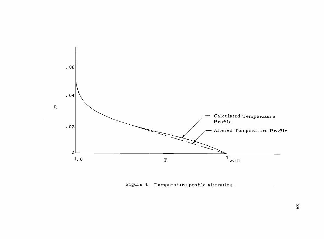
profile (for heating). To hasten the convergence of the temperature,
the calculated temperature profile is altered for the third and the
fourth X increments; no further alterations are applied. The

24
calculated temperature profile for the third (and fourth) X incre-
ment has the general shape shown in Figure 4. A temperature pro-
file with a straight-line slope from the wall more nearly represents
the actual temperature distribution (15, p. 287-290). Therefore,
a screening procedure is used to detect the inflection of the calcu-
lated temperature profile, and a straight line from the inflection to
the wall is substituted for the calculated profile (see Figure 4).
That is done at the third and fourth X increments only; no further
alterations are made downstream from there. Such a procedure to
hasten convergence is not needed for the case where the flux is
known since the extremely severe step change of temperature
boundary condition is not imposed.
Since calculation for heat transfer rates involves the differ-
ence in mean temperatures, accurate evaluation of the mean tem-
perature is imperative. In dimensionless variables the mean tem-
perature is defined by an integral:
1/2= 8 S TURdR.Tmean
0
For accurate evaluation of the integral, an integration procedure
based on the assumption that adjacent values of the integrand lie on.
a parabola (as in Simpson's rule) is used for calculating the mean
temperature. Simpson's rule as such is not conveniently used in
R
. 06
. 04
. 02
0
Calculated TemperatureProfileAltered Temperature Profile
1. 0 T Twall
Figure 4. Temperature profile alteration.
26this case because of having unequal sizes. The same type integration
procedure is used for calculating the mean velocity for monitoring
purposes. However, the trapezoidal rule is sufficiently accurate for
use in calculating velocities (the continuity equation appended to the
momentum equations) and is much more convenient for that purpose.
Results
The results for pipe flow are organized into the following four
groups: 1) Checks against known analytical solutions, 2) Results with
temperature independent viscosity for a range of the exponent n
with uniform heating, 3) Solutions with temperature-dependent vis-
cosity with uniform heating, and 4) Results with temperature-
dependent viscosity with sinusoidal heating.
The first check of the results generated by the present program
is comparison with the Sellars, Tribus, and Klein (36) analytical
solutions for Newtonian flow with a uniform-temperature pipe wall
and with uniform heat flux. For the uniform-temperature pipe wall
the local and mean Nusselt numbers over the range where comparison
is possible are presented in Figure 5. The values of both local and
mean Nusselt numbers from the present numerical solution are
within one percent of the values from the analytical solution over the
range 1 of X from X = 0. 014 to X = 0.100. The Nusselt numbers
1 For clarification of the physical meaning of the values citedfor X, one may convert X to the ratio of the distance from the pipeentrance to the pipe diameter. The ratio x/D is obtained by multiply-X by the product of Re andPr (x/D;;;XRePr). If one takes Re = 100 andPr =1 for illustrative purposes, X= 0. 100 is equivalent to x/D == 10.For very viscous Newtonian fluids and for most non-Newtonian flowsPr = 1000 is more nearly typical than is Pr = 1. Then for Re = 100and Pr = 1000, X = 0. 100 corresponds to x/D 7-* 10, 000.

7
6
5
4
3
NUSSELT NUMBERS FOR PIPE FLOW
Uniform Wall TemperatureFully Developed Velocity ProfileTemperature-Independent Viscosity
n= 1. 00
Meaki
Local
0 0. 05
xDRePr
0. 10
Figure 5. Nusselt numbers for pipe flow with uniform temperature pipe wall - n = 1. 00.

28
from the present solution are slightly higher over that range of X.
For uniform heat flux the local Nusselt number is shown in Figure 6
for the range of X where comparison is made. Over the range of X
from X = 0. 008 to X = 0. 100 the values of the local Nusselt number
from the solution reported here are within one percent of the values
from the Sellars, Tribus, and Klein solution. The Sellars, Tribus,
and Klein solution loses accuracy rapidly for smaller values of X
because of truncation of the series solution (20, p. 130). Since only
five terms were used, comparison is not made for small values of X.
A second check of the present solution is accomplished by
comparison with McKillop's (27) results for n = 0. 50 with temper-
ature-independent viscosity. For uniform temperature pipe wall
the values of local Nusselt number show a mean square difference
of 1. 2 percent from the values reported by McKillop (27, p. 856).
The mean square difference is 0. 5 percent for local Nusselt num-
bers with uniform heat flux. In both cases the values reported by
McKillop are in the range from X = 0. 0025 to X = 0. 075.
Comparison with the results of Christianson and co-workers
(6, 7, 8) shows close agreement with their numerical solution for
temperature-independent viscosity but large differences for
temperature-dependent viscosity. An intuitive argument concern-
ing the shape of the Nusselt number curves seems to support the
results of the solution reported here. To make the desired

7
6
5
4
3
LOCAL NUSSELT NUMBER FOR PIPE FLOWUniform Heat Flux
Fully Developed Velocity ProfileTemperature-Independent Viscosity
n= 1. 00
"%.,..........,...,
0. 05
xDRePr
0. 10
Figure 6. Local Nusselt number for pipe flow with uniform heat flux - n = 1. 00.

30
comparison, the results of the present solution were recast into the
form used by Christiansen and co-workers. In their work Graetz
[number Gz = Tr-11 replaces X used here, and the average Nusselt4 X
number based on the arithmetic mean temperature difference is used
instead of the mean Nusselt number based on the log mean temperature
difference. In Figure 7 is shown the average Nusselt number for
n = 1. 00 with 4, = 0 (temperature-independent viscosity) and (p = 2
(a case of temperature-dependent viscosity) for uniform temperature
pipe wall. For temperature-independent viscosity, the two sets of
results compare rather well. The present solution yields average
Nusselt number about one percent higher over the range Gz = 10 to
-Gz = 1000 ( X = 7.85 x 10 to X = 7.85 x 10⁻⁴). The difference
increases from one percent to about four percent in the Graetz num-
ber decade from Gz = 1000 to Gz = 10, 000 (X = 7.85 x 10⁻⁴ to
X = 7.85 x 10⁻⁵). For the case of temperature-dependent viscosity
comparison is hopeless; at large Graetz number (small X) the
average Nusselt number reported by Christiansen and co-workers
is considerably greater than the result from the present solution.
The following argument concerning the shape of the Nusselt number
curves is thought to lend support to the results generated by the
present solution. The effect of heating a liquid with temperature-
dependent viscosity is a flattening of the velocity profile. Thus one
expects the Nusselt number to be increased, compared to the

100
10
1
AVERAGE NUSSELT NUMBER FOR PIPE FLOWUniform Wall Temperature
Temperature-Dependent Viscosityn = 1. 00 Pr = 1S-00
...--......
....-../
....--..-- ...--
2..--
...--
.0,-
../...---
............0.00'..1.--
...---
.....'..- ...-
4, = 0
... .....-...--
.....--...---
.....Results of Christiansen, et al_..-
...--......
...-
..., ....-
....Results of present solution
10 100 1000
Gz
10, 000 100, 000
Figure 7. Average Nusselt number for pipe flow with uniform temperature pipe wall - n = 1. 00.

32
Nusselt number for a temperature-independent fluid, as the liquid
flows down the pipe. As the temperature of the liquid becomes more
nearly uniform, no doubt that trend is reversed as the fully-
developed isothermal profile is once again approached. However,
the concern here is with the region near the pipe inlet (large values
of the Graetz number). Near the inlet of the pipe the Nusselt num-
bers for the temperature-dependent and the temperature-independent
fluids are expected to be approximately equal. The Nusselt number
of the fluid with temperature-dependent viscosity is expected to
increase, compared to that for the temperature-independent fluid,
as the fluid is heated in flowing along the pipe. Of the two solutions
shown in Figure 7, only the solution reported here shows that an
characteristic. No explanation for the difference in the
Nusselt number from the two solutions is presently known.
The local Nusselt number for uniform flux and temperature-
independent viscosity is given in Figure 8. Values of Nusselt num-
ber are presented for four values of the exponent n. The Nusselt
number for Newtonian flow is plotted in the upper portion with the
other three values given in the lower portion as ratios of the local
Nusselt number to the value of local Nusselt number for Newtonian
flow at the same value of X. For n = 0. 25 the Nusselt number is
19 percent higher than for Newtonian flow near the inlet and 22 per-
cent higher at X = 0.100. Values of Nusselt number for n = 0. 50

0
0:1
f24
z
100
10
LOCAL NUSSELT NUMBER FOR PIPE FLOW
Uniform Heat FluxFully Developed Velocity ProfileTemperature-Independent Viscosity
n -= 1. 00
3. 0
1. 30
1. ZO
1. ln
1. 0010-5
n = . 25
5 0
n _ 75
10-2 10-110-4 10-3
x
DRePr
Figure 8. Local Nusselt number for pipe flow with uniform flux n = 0. 25, 0. 50, 0. 75, and 1. 00.

34
and n=- 0.75, of course showed smaller departure from the values
for Newtonian flow.
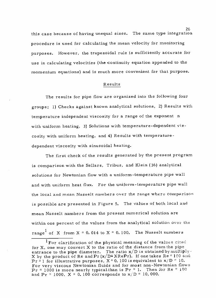
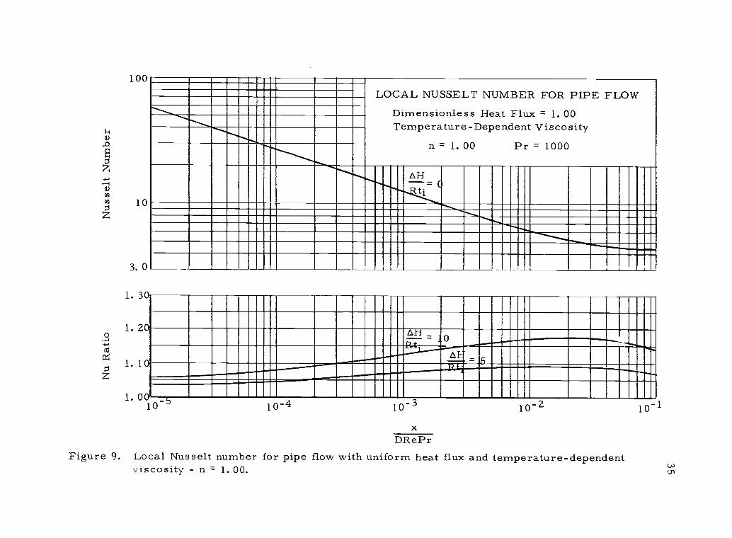
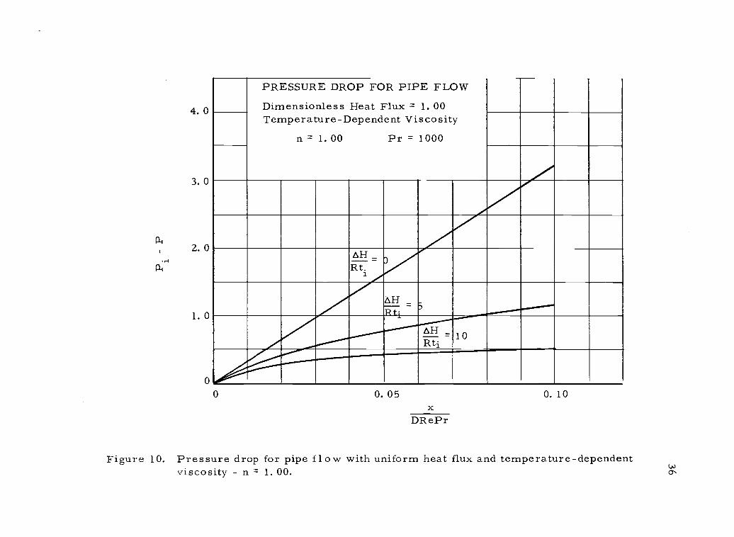
For temperature-dependent viscosity and uniform heat flux,
local Nusselt number and pressure drop are shown in Figures 9
through 16. For the calculations of Figures 9 through 12 the expo-
nent n is unity; Figures 9 and 10 are for dimensionless heat flux
equal to 1. 00; and Figures 11 and 12 are for dimensionless heat flux
equal to 2. 00. Consistent with expectations, temperature-dependent
viscosity increases the heat transfer rate (Nusselt number) and de-
creases the pressure drop for situations where heating occurs. For
the most severe2 ca s e checked (Flux = 2. 00 and AH/Rti = 10), the
Nusselt number ratio reaches a peak value about 27 percent greater
than for the case of temperature-independent viscosity; for that
2The severity of a heating condition is related to the amountof viscosity change caused by the temperature change-temperaturedependence combination. Thus high values of heat flux combinedwith high values of AH/Rti are considered as severe heating con-ditions. To illustrate the physical magnitude implied by a givenvalue of Flux, one may convert Flux to heat flux (VA = Flux kti/D)by selecting some representative values for k, ti, and D. If onetakes k = 0. 10 Btu/hr-ft-F, ti = 500 R, and D = 2 inches forillustration sake, the value of VA = 300 Flux Btu/hr-ft2. Theeffect of a given value of AI-I/Rti is best understood by consideringthe viscosity c..nge/c_aused,,xla given change in fluid temperature
Al-1/Ktiv1/ - 1/tri 1/n2 = e 61 for a fluid with n = 1). To il-lustrate this effect, one may take t1= 500R and AH/Rt.
1
= 10; forthose conditions the viscosity is reduced by a factor of 2. 5 whenthe fluid is heated from 500R to 550R.
100
10
3. 0
1. 30
1. 20
1. 10
LOCAL NUSSELT NUMBER FOR PIPE FLOW
Dimensionless Heat Flux = 1. 00Temperature-Dependent Viscosity
n = 1. 00 Pr = 1000
Ali= 0ti
z1. 00:-5--
10 10 -4 10-3
x
DRePr
10 -2
Figure 9. Local Nusselt number for pipe flow with uniform heat flux and temperature-dependentviscosity - n = 1. 00. u-1
P-1
4. 0
3. 0
2. 0
1. 0
PRESSURE DROP FOR PIPE FLOW
Dimensionless Heat Flux = 1. 00Temperature-Dependent Viscosity
n = 1. 00 Pr = 1000
AliRt.
1
Al-ID
AH _ 10Rti
0 0. 05x
DRePr
0. 10
Figure 10. Pressure drop for pipe flow with uniform heat flux and temperature-dependentviscosity - n = 1. 00.
0
P4
z
100
10
3. 0
1. 30
1. 20
1.10
LOCAL NUSSELT NUMBER FOR PIPE FLOW
Dimensionless Heat Flux = 2. 00Temperature-Dependent Viscosity
n = 1. 00 Pr = 1000
AH0Rti
1. 00-10-5 10-4 10-3
x
DRePr
10-2
Figure 11. Local Nusselt number for pipe flow with uniform heat flux and temperature-dependentviscosity - n = 1. 00.
4. 0
3. 0
2. 0
1. 0
0
PRESSURE DROP FOR PIPE FLOW
Dimensionless Heat Flux = 2. 00Temperature-Dependent Viscosity
n = 1. 00 Pr = 1000
off= 0
Rt.1
AFT5Rt.
1
= 10-ARt;
0 0. 05 xDRePr
0. 10
Figure 12. Pressure drop for pipe flow with uniform heat flux and temperature-dependentviscosity - n = 1. 00.

100
10
3. 0
1. 30
0 1. 20
4Crl
C4
z1. 10
1. 00
LOCAL NUSSELT NUMBER FOR PIPE FLOW
Dimensionless Heat Flux = 1. 00Temperature-Dependent Viscosity
n = 0. 75 Pr = 1000
LH= 0Rt.
AH10Rti
10-5 10-4
= 5Rti
10-3x
DRePr
10-2
Figure 13. Local Nusselt number for pipe flow with uniform heat flux and temperature-dependent viscosity - n = 0. 75.

0-1
4. 0
3. 0
2. 0
1. 0
0
PRESSURE DROP FOR PIPE FLOW
Dimensionless Heat Flux = 1. 00Temperature-Dependent Viscosity
n = 0. 75 Pr = 1000
OH =ORti
AH = 5Rti
A10
0 0. 05x
DRePr
0. 10
Figure 14. Pressure drop for pipe flow with uniform heat flux and temperature-dependentviscosity n-= 0. 75.

0
z 1. OG
100
10
3. 0
1.30
1.20
1.10
LOCAL NUSSELT NUMBER FOR PIPE FLOW
Dimensionless Heat Flux = 1. 00Temperature-Dependent Viscosity
n = 0. 50 Pr = 1000
off = 0Rti
AHRt.
10-5 10-4Rt 5
10-3x
DRePr
10-2 10-1
Figure 15. Local Nusselt number for pipe flow with uniform heat flux and temperature-dependentviscosity - n = 0. 50.

4. 0
3. 0
2. 0
PRESSURE DROP FOR PIPE FLOW
Dimensionless Heat Flux = 1. 00Temperature-Dependent Viscosity
n = 0. 50 Pr = 1000
OH =ORt.
1
A5
li A=
r_i
/1110Rti
.,-/"...-
0 0.05 xDR ePr
0. 10
Figure 16. Pressure drop for pipe flow with uniform heat flux and temperature-dependentviscosity - n = 0. 50.
43
same set of conditions the pressure drop from the inlet to X = 0.100
is only seven percent as great as for temperature-independent
viscosity. Figures 13 through 16 show similar Nusselt number and
pressure drop effects for n = 0.75 and n = 0.50. Since tempera-
ture-dependent viscosity causes flattening of the velocity profile for
heating, the Nusselt number and pressure drop are affected less for
smaller values of the exponent n where the velocity profile is al-
ready flattened because of the shear-stress shear-rate relationship.
Nevertheless, inspection of Figures 13 through 16 readily shows that
sizeable heat transfer rate and pressure drop effects are caused by
temperature induced viscosity changes. Some of those effects are
summarized below;
.6HRt.n
Pressure drop from inlet toPeak value X = 0.10 as percent of pres-of Nusselt sure drop for temperature-
Flux number ratio independent viscosity
1 5 1 1.09 36
1 10 1 1.18 16
1 5 2 1.14 21
1 10 2 1.27 7
. 75 5 1 1.09 46
.75 10 1 1.16 24
. 50 5 1 1.08 59
. 50 10 1 1.14 36

44
An interesting and potentially useful example of non-uniform
heat flux distribution is the case where the heat flux varies sinu-
soidally along the pipe. Such a situation could occur in a nuclear
reactor (20, p. 140). Figures 17 through 20 show wall temperature,
mean temperature, heat flux, and pressure drop for n = 1. 00 and
n = 0. 50. Since the heat flux is the same in every case, the mean
temperature for all cases is the same at any given value of X. As
anticipated the wall temperature and pressure drop are lower for
temperature-dependent viscosity than for the case where viscosity is
independent of temperature.
In discussing the results, the problem of instability of the
numerical solution under some conditions must be pointed out for
the benefit of any potential user of the present numerical solution.
In spite of the efforts made to insure a stable solution, unstable be-
havior is shown for unfavorable combinations of the parameters.
The non-linear nature of the momentum equation and the necessity
for coupled solution of the energy and momentum equations make
impossible the theoretical determination of an appropriate grid size
for stable solution under a given set of parameters. Empirical de-
termination of an appropriate grid size must be employed. Anyone
considering use of the present numerical solution is cautioned that
such a procedure can be very costly and time-consuming if severe
conditions are imposed on the parameters.
a)
Cd
a)
a)
CO
1 10a)
'at0
U)
a)
1.05
1. 20
1. 15
1. 00
TEMPERATURES FORHEATING
Temperature-DependentViscosity
n = 1. 00 Pr = 1000
SINUSOIDA
Wall eWall Te perat ire TemperateLH
0 A(ATli = 10)
(P,ti
A
Flux
AllAlM-an Temperature
0 0. 005x
DRePr
3. 2
2. 4
t. 6
.8
0
O. 010
Figure 17. Temperatures for sinusoidal heating - n = 1. 00.
PRESSURE DROP FOR SINUSOIDAL HEATINGTemperature-Dependent Viscosity
n = 1. 00 Pr = 1000
API= 0 Ali
= 10Rt.i Rt
O. 005 xDRePr
O. 010
Figure 18. Pressure drop for sinusoidal heating - n = 1. 00.

1. 20
1. 15
1. 10
1. 05
1. 000
TEMPERATURES FOR SINUSOIDAL
Temperature-Dependentn = 0., 50
HEATING
Viscosity?r = 1000
an Ternpelature(A1-1Rti t o)
Wall
(
Temperature
10)REI1
Flux
/ Mean Temperature
O. 005 xDRePr
3. 2
2. 4
1. 6
.8
0
o. 010
Figure 19. Temperatures for sinusoidal heating - n = 0. 50.

PRESSURE DROP FOR SINUSOIDAL HEATING
Temperature-Dependent Viscosityn = 0. 50 Pr = 1000
off== 0 10Rti Rti
0 0. 005 xDRePr
0. 010
Figure 20. Pressure drop for sinusoidal heating - n = 0. 50.

49
III. CHANNEL FLOW
Differences from Treatment of Pipe Flow
Since the solution for flow in a channel between two flat,
parallel plates is so nearly like that for pipe flow, only the main
differences between the two will be discussed.
The equations of change for channel flow of course do not have
the terms involving curvature. Justification of the simplified equa-
tions from those given by Bird, Stewart, and Lightfoot (3, p. 84,
88, 319) follows the same arguments given in Appendix II for the
pipe flow equations. In dimensionless form the equations of change
are as follows:
Energy Equation:
8x T aa
T a T + BrS2
U + V = 1'aY 2ay
Momentum Equation:
1 au au dP
ay
sL2L as auPr 8X 8Y dX 2 8Y 8Y
Continuity Equation (Differential Form):
av au+ = oay ax
50
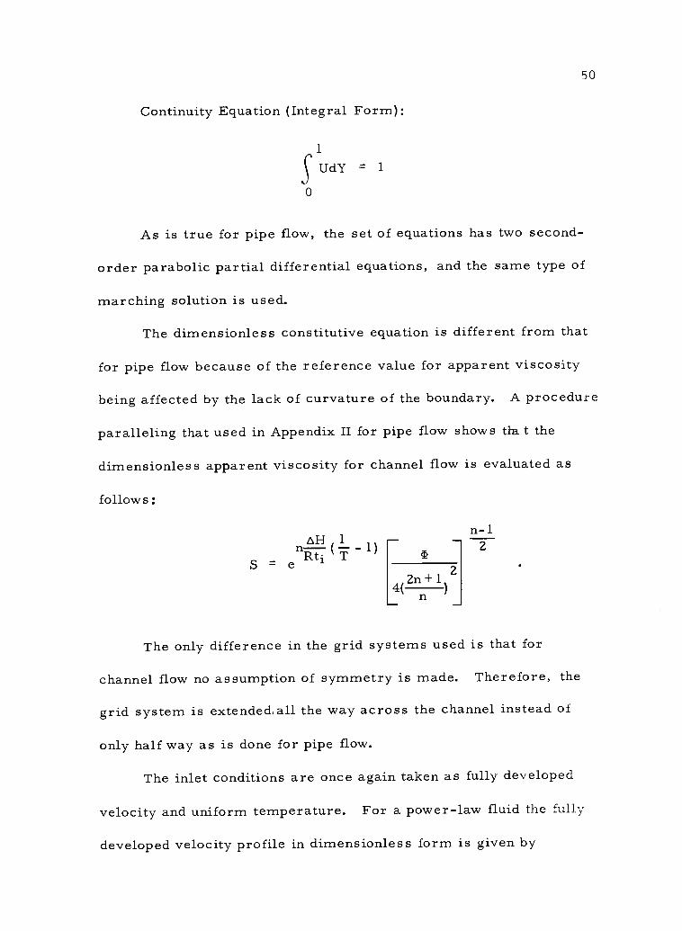
Continuity Equation (Integral Form):
1
UdY = 1
0
As is true for pipe flow, the set of equations has two second-
order parabolic partial differential equations, and the same type of
marching solution is used.
The dimensionless constitutive equation is different from that
for pipe flow because of the reference value for apparent viscosity
being affected by the lack of curvature of the boundary. A procedure
paralleling that used in Appendix II for pipe flow shows tl-a t the
dimensionless apparent viscosity for channel flow is evaluated as
follows:
AH , 1
Tn-
1
- i)RtS = e
4(2n + 1)2
n
n-12
The only difference in the grid systems used is that for
channel flow no assumption of symmetry is made. Therefore, the
grid system is extended, all the way across the channel instead of
only half way as is done for pipe flow.
The inlet conditions are once again taken as fully developed
velocity and uniform temperature. For a power-law fluid the fully
developed velocity profile in dimensionless form is given by
51
2n +1U n+1 [1 - 12y-11 n ].
n +1
This expression is developed from the channel-flow analog of the
procedure used by Wilkinson (40, p. 61-63) for pipe flow. (Substi-
tution of unity for n yields the familiar parabolic velocity distribu-
tion for Newtonian fluids where the maximum velocity is 50 percent
greater than the average velocity. )
To apply the boundary conditions to channel flow, only the wall
conditions are used. For the velocity, boundary conditions which
apply are U = 0 and V = 0 at each wall. The wall-temperature or
heat-flux boundary conditions are handled independently to allow the
two walls to have different temperature or flux conditions.
Results
The results for channel flow are organized into the following
four groups: 1) Check against known analytical solutions, 2) Results
with temperature-independent viscosity for a range of the exponent n
with uniform, symmetrical heating, 3) Solutions with temperature-
dependent viscosity for n = 1 with uniform, symmetrical heating,
and 4) Results with temperature-dependent viscosity for n = 1 with
non- symmetrical heating.
The principal check of the results generated by the present

52
program is a comparison with the Sellars, Tribus, and Klein (36)
analytical solution for Newtonian flow with uniform-temperature
walls. Both the local and mean Nusselt numbers over the range
where comparison is possible are presented in Figure 21. The
values of both local and mean Nusselt numbers from the present
numerical solution are within one percent of the values from the
analytical solution over the range3 of Z from Z = 0. 006 to Z = 0. 0725.
The Nusselt numbers from the present solution are slightly higher
over that range of Z. The Sellars, Tribus, and Klein solution loses
accuracy rapidly for smaller values of Z because of truncation of
the series solution (20, p. 130). Since only three terms were used,
comparison is not made for small values of Z.
An additional check of the numerical solution is furnished by
comparing the local Nusselt number at large Z with the value for a
fully-developed-temperature profile for the uniform heat flux
boundary conditions. For Z greater than Z = 0.055 the local Nus-
selt number generated by the present solution is within 0. 15 percent
of the accepted value of N = 8. 235 for Newtonian flow (20, p. 117).
The local Nusselt number for uniform flux and temperature-
3Physical interpretation of values cited for Z may be madeby converting Z to the ratio of distance from the channel inlet tothe distance between the two flat plates. Calculation of the x/L ratiois accomplished by multiplying Z by the product of Re' andPr (x/L = ZRe'Pr). Then for Re' = 100 and Pr = 1000, Z = 0. 0725corresponds to x/1_, = 7250.

11. 0
10. 0
9. 0
8. 0
NUSSELT NUMBERS FOR CHANNEL FLOWUniform Wall Temperature
Fully Developed Velocity ProfileTemperature-Independent Viscosity
n= 1. 00
Mearl
Local
7. 00 0. 025 0. 050 0. 075x
LRe 'Pr
Figure 21. Nusselt numbers for channel flow with uniform temperature walls - n = 1. 00.

54
independent viscosity is given in Figure 22. Values of Nusselt num-
ber are presented for four values of the exponent n. The Nusselt
number for Newtonian flow is plotted in the upper portion with the
other three values given in the lower portion as ratios of the local
Nusselt number for Newtonian flow at the same value of x/(LRe'Pr).
For n = 0. 25 the Nusselt number is 25 percent higher than for
Newtonian flow near the inlet and 14 percent higher far downstream.
Values of Nusselt number for n = 0. 50 and n = 0. 75, of course,
showed smaller departure from the values for Newtonian flow.
For temperature-dependent viscosity, both Nusselt number
and pressure drop are shown in Figures 23 and 24 respectively. For
those calculations the exponent n is unity and the heat flux is both
symmetrical and uniform. For the conditions of the calculations,
the local Nusselt number ratio reaches a peak value about eight per-
cent greater for temperature-dependent viscosity than for the case
of temperature-independent viscosity. The pressure drop from the
inlet to x/(LRe'Pr)=0.0725 for the temperature-dependent viscosity
is only 40 percent of that for the case where viscosity is independent
of temperature.
An interesting use can be made of the present numerical solu-
tion by allowing the two walls to have different thermal boundary
conditions. Figures 25 and 26 show the results of two such calcula-
tions. The thermal boundary conditions used in generating

100
10
5
1. 30
1. 20
1. 10
1..00]1- 510
LOCAL NUSSELT NUMBER FOR CHANNEL FLOWUniform Wall Heat Flux
Fully Developed Velocity ProfileTemperature-Independent Viscosity
n = 1, 00
n
=,.21=1:=
10-4111111,
MN/
n = 0.n = 0.
5075
10-3x
LRe'Pr
Figure 22. Local Nusselt number for channel flow with uniform wall heat flux n = 0. 25, 0. 50,0. 75, and 1. 00.

100
10
5
1. 30
1. 0010-5
LOCAL NUSSELT NUMBER FOR CHANNEL FLOWDimensionless Heat Flux = 1. 00Temperature-Dependent Viscosity
n = 1. 00 Pr = 1000''.**"..**--.....................,...,...........
-'''%-...".."'''"*".......................... 11-1=Rti 0
AHRti 5
10-4 10-3x
LRe'Pr10-2
Figure 23. Local Nusselt number for channel flow with uniform wall heat flux and temperature-dependent viscosity - n = 1. 00.

4. 0
3. 0
2. 0
1. 0
0
PRESSURE DROP FOR CHANNEL FLOWDimensionless Heat Flux = 1. 00Temperature-Dependent Viscosity
n = 1. 00 Pr = 1000
AH= 0Rt.
1
AFT = 5Rt.
0 0. 025x
LRe,'Pr
0. 050
Figure 24. Pressure drop for channel flow with uniform wall heat flux and temperature -dependent viscosity - n = 1. 00.
O. 075
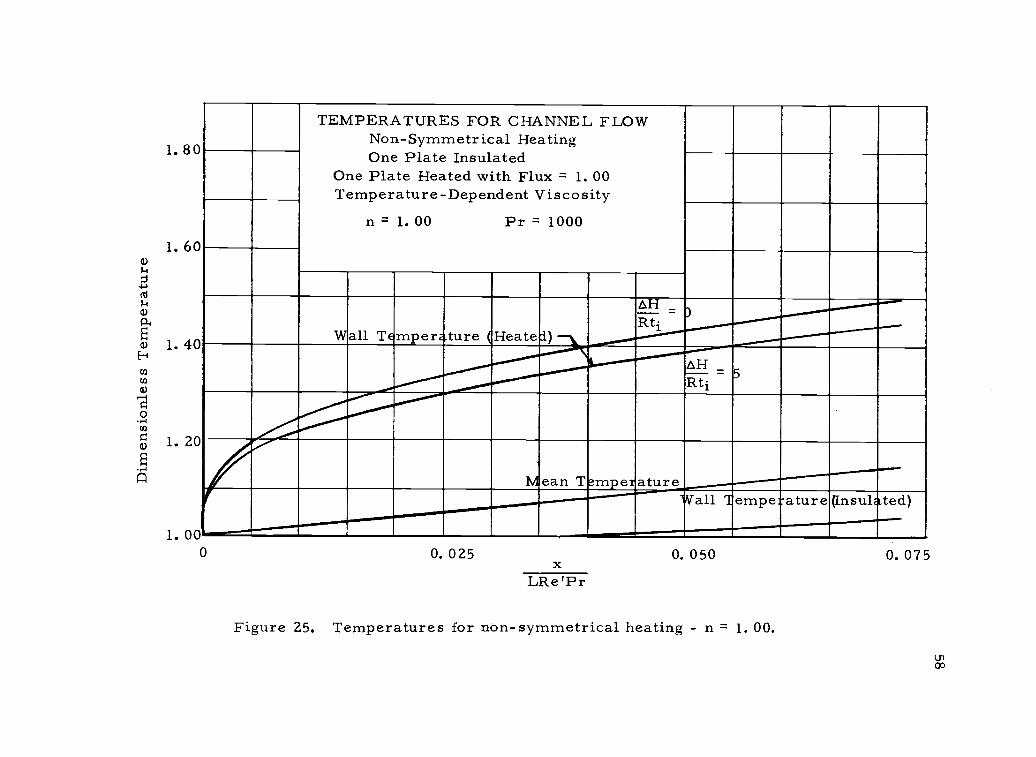
1. 80
1. 000
TEMPERATURES FOR CHANNEL FLOWNon-Symmetrical HeatingOne Plate Insulated
One Plate Heated with Flux = 1. 00Temperature-Dependent Viscosity
n = 1. 00 Pr = 1000
Wall Temperature Heate
EHRti
AliRti
can T-mperatureWall Temperature (Insulated)
0. 025x
LRe 'Pr
O. 050
Figure 25. Temperatures for non-symmetrical heating - n = 1. 00.
0.075

PRESSURE DROP FOR CHANNEL FLOWNon-Symmetrical HeatingOne Plate Insulated
One Plate Heated with Flux = 1. 00Temperature-Dependent Viscosity
n = 1. 00 Pr,= 1000
AH= 0
i
. .
AH = 5Rt
0 O. 025x
LRe'Pr0. 050
Figure 26. Pressure drop for non-symmetrical heating - n = 1. 00.
0. 075

60
Figures 25 and 26 call for one wall insulated and one wall uniformly
heated. The two fluid conditions are for n = 1. 00 and temperature-
independent viscosity in one case and temperature-dependent vis-
cosity in the other. In Figure 25 are shown the two wall tempera-
tures and the mean temperature. Since the flux has the same value,
the mean temperature is the same for both cases. The temperature
of the insulated wall is the same in both cases, but the temperature
of the heated wall is approximately four percent lower at
x/(LRe'Pr)= 0.0725 for the temperature-dependent condition used.
To convert that to temperature difference instead of dimensionless
temperature, one may assume, for sake of illustration, a reasonable
inlet temperature of 500*R; with that inlet temperature, the tem-
perature of the heated wall at x/(LRe'Prr- 0.0725 is 750*R for
temperature-independent viscosity and 720eR for temperature-
dependent viscosity. The pressure drop results in Figure 26 show
a large difference because of the temperature-dependent viscosity.
The pressure drop from the inlet to x/(LRe'Pr) = 0. 0725 is approxi-
mately 66 percent as great for the temperature-dependent situation
as for the case of temperature-independent viscosity.
As is true for pipe flow, unfavorable combinations of the
parameters produce an unstable solution. Once again no theoretical
basis is known for determination of an appropriate grid for stability;
a suitable grid size must be arrived at empirically.

61
IV. CONCLUSIONS
1. A numerical solution is presented for the coupled energy
and momentum equations for laminar flow of temperature-dependent
power-law non-Newtonian fluids. Two important geometrical cases
are considered: pipe flow and channel flow between two flat, parallel
plates. For pipe flow, axially varying wall temperature or heat flux
boundary conditions may be handled. Similarly, for channel flow,
non-symmetrical and non-uniform thermal boundary conditions may
be imposed.
2. For heating of a liquid with temperature-dependent vis-
cosity, the Nusselt number is shown to be greater than for a liquid
with temperature-independent viscosity, and the pressure drop is
shown to be smaller than for a liquid with no viscosity-temperature
dependence. Both the heat transfer and the pressure drop effects
of temperature-dependent viscosity are sufficiently large to merit
consideration in many design situations.
3. A major problem in applying the present solution is se-
lection of an appropriate grid size to produce a stable solution.
Since theoretical criteria for determination of an appropriate grid
are not known, the grid size for a stable solution with a given set
of conditions must be arrived at empirically.

V. RECOMMENDATIONS FOR FURTHER INVESTIGATION
1.
62
The solution presented is suitable or readily adapted for
investigation of a number of important situations which were not
covered in this report. Cooling, viscous dissipation, and combined
hydrodynamic-thermal entry length problems are a few important
applications for which the numerical solution presented here should
be suitable. In addition, problems with non-uniform thermal
boundary conditions can be realistically solved.
2. As for any analytical solution, careful laboratory checking
of the results is recommended.
3. Since selection of a suitable grid size for stable numerical
solution must now be done empirically, criteria for selection of an
appropriate grid need to be established.
4. An interesting extension of the work reported here is the
three-dimensional problem involved in accounting for circum-
ferential variation of the thermal boundary conditions for pipe flow.
For example, any application where there is thermal radiation to
pipes is likely to cause such circumferential variations.

63
BIBLIOGRAPHY
1. Accidentally developed "elastic water" flows over edge of up-right pitcher until snipped by scissors. The Oregonian(Portland, Oregon) p. 25, col. 1-8. Dec. 8, 1966.
2. Alves, G. E. , D. F. Boucher and R. L. Pigford. Pipe-linedesign for non-Newtonian solutions and suspensions. ChemicalEngineering Progress 48:385-393. 1952.
3. Bird, R. Byron, Warren E. Stewart and Edwin N. Lightfoot.Transport phenomena. New York, Wiley, 1960. 780 p.
4. Bodoia, John Rodger. The finite difference analysis of confinedviscous flows. Ph. D. thesis. Pittsburgh, Pa. , CarnegieInstitute of Technology, 1960. 117 numb. leaves.
5. Bodoia, John Rodger and J. F. Osterle. Finite differenceanalysis of plane Poiseuille and Couette flow developments.Applied Scientific Research, sec. A, 10:265-276. 1961.
6. Christiansen, E. B. and S. E. Craig, Jr. Heat transfer topseudoplastic fluids in laminar flow. Journal of the AmericanInstitute of Chemical Engineers 8:154-160. 1962.
7. Christiansen, E. B. and Gordon E. Jensen. Energy transfer tonon-Newtonian fluids in laminar flow. In: Progress in inter-national research on thermodynamic and transport properties,ed. by Joseph F. Masi and Donald J. Tsai. New York,Academic, 1962. p. 738-747.
8. Christiansen, E. B. , Gordon E. Jensen and Fan-Sheng Tao.Laminar flow heat transfer. Journal of the American Instituteof Chemical Engineers 12:1196-1202. 1966.
v, 9. Coupal, Bernard. Studies on temperature profiles for non-Newtonian fluids in pipe flow. Ph. D. thesis. Gainesville,Fla. , University of Florida, 1965. 175 numb, leaves.(Microfilm)
10. Eringen, A. Cemal. Nonlinear theory of continuous media.New York, McGraw-Hill, 1962. 477 p.

64
11. FlUgge, Wilhelm. Viscoelasticity. Waltham, Mass. , Blaisdell,1967. 127 p.
12. Fredrickson, Arnold Gerhard. Principles and applications ofrheology. Englewood Cliffs, N. J. , Prentice-Hall, 1964. 326 p.
\, 13. Gee, R. E. and J. B. Lyon. Nonisothermal flow of viscous non-Newtonian fluids. Industrial and Engineering Chemistry49:956-960. 1957.
14. Heaton, H. S. , W. C. Reynolds and W. M. Kays. Heat transferin annular passages. Simultaneous development of velocity andtemperature fields in laminar flow. International Journal ofHeat and Mass Transfer 7:763-781. 1964.
15. Hsu, Shao Ti. Engineering heat transfer. Princeton, N. J. ,Van Nostrand, 1963. 613 p.
16. Hwang, Ching-Lai. A finite difference analysis of magneto-hydrodynamic flow with forced convection heat transfer. Ph. D.thesis. Manhattan, Kan. , Kansas State University, 1962. 123numb. leaves. (Microfilm)
17. Hwang, Ching-Lai and Liang-Tsing Fan. Finite differenceanalysis of laminar magnetohydrodynamic flow in the entranceregion of a flat rectangular duct. Applied Scientific Research,sec. B, 10:329-343. 1963.
18. Hwang, Ching-Lai and Liang-Tsing Fan. Finite differenceanalysis of forced convection heat transfer in entrance regionof a flat rectangular duct. Applied Scientific Research, sec.A, 13:401-422. 1964.
v 19. Inman, Robert M. Heat transfer to laminar non-Newtonian flowin a circular tube with variable circumferential wall tempera-ture or heat flux. Cleveland, Ohio, 1965. 22 p. (U. S.National Aeronautics and Space Administration. TechnicalNote D-2674. )
20. Kays, W. M. Convective heat and mass transfer. New York,McGraw-Hill, 1966. 387 p.
21. Kays, W. M. Numerical solutions for laminar-flow heat trans-fer in circular tubes. Transactions of the American Society ofMechanical Engineers 77 :1265 -1274. 1955.

65
22. Kettleborough, C. F. Poiseuille flow with variable fluidproperties. Transactions of the American Society of MechanicalEngineers, Journal of Basic Engineering, ser. D, 89:666-676.1967.
23. Koppel, L. B. and J. M. Smith. Laminar flow heat transfer forvariable physical properties. Transactions of the AmericanSociety of Mechanical Engineers, Journal of Heat Transferser. C, 84:157-163. 1962.
`v 24. Korayem, Aly Yosry. Non-isothermal laminar flow of non-Newtonian fluids in the entrance region of a pipe. Ph. D. thesis.Davis, Calif., University of California at Davis, 1964. 121
numb, leaves. (Microfilm)
25. Lipkis, R. P. Discussion of: Heat transfer to laminar flow ina round tube or flat conduit-The Graetz problem extended, byJ. R. Sellars, Myron Tribus and J. S. Klein. Transactions ofthe American Society of Mechanical Engineers 78:441-448.1956.
26. Lyche, Bjorn C. and R. Byron Bird. The Graetz-Nusseltproblem for a power-law non-Newtonian fluid. ChemicalEngineering Science 6:35-41. 1956.
27. McKillop, A. A. Heat transfer for laminar flow of non-Newtonianfluids in entrance region of a tube. International Journal ofHeat and Mass Transfer 7:853-862. 1964.
28. Metzner, A. B. Heat transfer in non-Newtonian fluids. In:Advances in heat transfer, ed. by J. P. Hartnett and T. F.Irvine, Jr. vol 2. New York, Academic, 1965. p. 357-397.
29. Pigford, R. L. Nonisothermal flow and heat transfer insidevertical tubes. Chemical Engineering Progress Symposium,ser. 17, 51:79-92. 1955.
30. Ree, Taikyue and Henry Eyring. Theory of non-Newtonian flow.Journal of Applied Physics 26:793-809. 1955.
31. Reynolds, W. C. Heat transfer to fully developed flow in acircular tube with arbitrary circumferential heat flux. Trans-actions of the American Society of Mechanical Engineers,Journal of Heat Transfer, ser. C, 82:108-112. 1960.

66
32. Reynolds, W. C. Turbulent heat transfer in a circular tube withvariable circumferential heat flux. International Journal of Heatand Mass Transfer 6:445-454. 1963.
33. Rohsenow, Warren M. and Harry Y. Choi. Heat, mass, andmomentum transfer. Englewoods Cliffs, N. J. Prentice-,Hall, 1.961.537 p.
34. Rosenberg, D. E. and J. D. Hellums. Flow development and heattransfer in variable-viscosity fluids. Industrial and EngineeringChemistry Fundamentals 4:417-422. 1965.
35. Seigel, R. , E. M. Sparrow and T. M. Hallman. Steady laminarheat transfer in a circular tube with prescribed wall heat flux.Applied Scientific Research, ser. A, 7:386-392. 1958.
36. Sellars, J. R. , Myron Tribus and J. S. Klein. Heat transfer tolaminar flow in a round tube or flat conduit--The Graetz problemextended. Transactions of the American Society of MechanicalEngineers 78:441-448. 1956.
37. Smith, G. D. Numerical solution of partial differential equations.New York, Oxford University, 1965. 179 p.
38. Thomas, David G. Transport characteristics of suspensions:application of different rheological models to flocculated sus-pension data. In: Progress in international research on thermo-dynamic and transport properties, ed. by Joseph F. Masi andDonald H. Tsai. New York, Academic, 1962. p. 704-717.
39. Welch, J. Eddie, Francis H. Harlow, John P. Shannon and BartJ. Daly. The MAC method--A computing technique for solvingviscous, incompressible, transient fluid-flow problems involvingfree surfaces. Los Alamos, New Mexico, 1966. 146 p. (LosAlamos Scientific Laboratory. Report No. LA-3425. )
40. Wilkinson, W. L. Non-Newtonian fluids. London, Pergamon,1960. 138 p.
41. Yau, Joseph and Chi Tien. Simultaneous development of velocltemperature profiles for laminar flow of a non-Newtonian
fluid in the entrance region of flat ducts. The Canadian Journalof Chemical Engineering 41:139-145. 1963.

67
APPENDIX I
COMPLETE TOPICAL LISTING OF THE LITERATURE
The numbers used below indicate the corresponding paper listed
in the Bibliography.
Geometry
Pipe: 6, 7, 8, 9. 11,
32, 34, 35, 36
Channel: 4, 14, 16, 17,
Entry Region
13, 14, 19, 21,
18, 22, 36, 41
22, 23, 24, 26,
17, 22, 24, 27,
18, 21, 22, 24,
6, 7, 8, 9, 13,
23,
27,
34
27,
16,
24,
31,
34,
18,
26,
32,
41
21,
27,
34,
22,
29,
35,
24,
31,
36Thermal: 6, 7, 8, 9,
Hydrodynamic: 4, 16,
Combined: 13, 14, 16,
Thermal Boundary Condition
Uniform Temperature:
27, 29, 34, 36, 41
Uniform Heat Flux: 14, 16, 18, 23, 26, 27, 35
Non-Uniform Temperature: 19, 22, 36
Non-Uniform Heat Flux: 19, 31, 32
Temperature Effect on Viscosity
Temperature-Independent:
Temperature-Dependent:
4,
22,
6, 7,
6, 7,
24,
8,
8,
26,
13,
9,
27,
22,
14,
34,
23,
16,
35,
24,
17,
36,
29,
18,
41
34
19,

68
APPENDIX II
DETAILS OF THE SIMPLIFICATION OF THE DIFFERENTIALEQUATIONS AND CONVERSION TO NUMERICAL EQUATIONS
Simplification of the Differential Equations
In this section of Appendix II a number of basic assumptions
are made, the equations of change subject to those assumptions are
given, the equations are further simplified by additional assumptions
and approximations, and then the equations are converted to dimen-
sionless form.
The following assumptions allow reduction of the basic equa-
tions of change in cylindrical-coordinates as given by Bird, Stewart,
and Lightfoot (3, p. 319, p. 8 3-91) to more concise form:
1. The flow is steady, incompressible, and laminar.
2. Symmetry about the centerline of the pipe exists.
3. Body forces are neglected.
4. The thermal conductivity and specific heat are uniform.
For the preceding conditions to be applicable the governing differ-
ential equations which apply to this problem are as follows:
Energy Equation:
P Cr U- rat atv-- =k[_1 a ,rat, a 111t 12
p ax ar r ar ar iax
2 2

Momentum Equations:
raT
u au + v au---] = aP r a(
xxr 8rpL ax ar ax L r Trx) +
ax
aTrxr aV av ap r ap u v-- J = - - L Lr )
ax ar ar r ar rr ax
Continuity Equation:
a(rv) auar ax
69
The energy equation can be further condensed by assuming that
axial diffusion of thermal energy (axial heat conduction) is negligible,
e. ,
< < 8222
aex r
With that simplification, the energy equation can be written as follows:
tu_at vat_ I. aat)] 2 a2 t 1 at IZ
11 p ax ar r 3r ar 2 2 r 3r 11 2ar
In reducing the momentum equations to tractable form, uni-
formity of pressure at any cross-section of the pipe is assumed.
Then and all other terms in the r-component of momentum8r
equation are assumed to be negligibly small compared to the terms
in the x-component equation. Thus only the x-component of
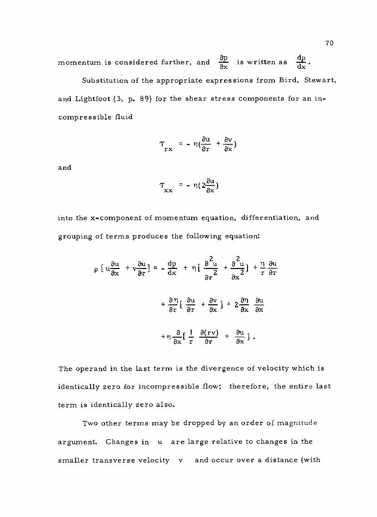
momentum is considered further, and 8pOx
is written as dpdx
70
Substitution of the appropriate expressions from Bird, Stewart,
and Lightfoot (3, p. 89) for the shear stress components for an in-
compressible fluid
and
au avT = - i( + )
T x Or Ox
T = - (2Oxxx Ox
into the x-component of momentum equation, differentiation, and
grouping of terms produces the following equation:
8u 8ur a u 2
p Lu +v--] = 11u] +11 au
Ox ar dxOr ax r ar
3/1 au av an 8u+ [ + 1 + 2 --
Or Or ax ax ax
a r 1 8(rv) au+ ax r Or ax
The operand in the last term is the divergence of velocity which is
identically zero for incompressible flow; therefore, the entire last
term is identically zero also.
Two other terms may be dropped by an order of magnitude
argument. Changes in u are large relative to changes in the
smaller transverse velocity v and occur over a distance (with

71
maximum value equal to ) which is small compared to distance
of interest in the axial direction. Thus the assumption is made that
8u avar
> > ax
Similarly the changes ofu in the radial direction are relatively
large compared to the changes of u in the axial direction; certainly
then the second derivatives in the respective directions are expected
to be of different order of magnitude:
u82u2
> > 822
ar ax
In addition the terms 81/8x and 8u/ax are individually small
compared to the other terms in the equation; therefore, their
product is deleted from the equation. With the simplifications indi-
cated above the resulting momentum equation is
p ur au au+ v = _ d E + 82uu au an auax 8r dx 2 r ar ar ar
To convert the equations of change to dimensionless form,
the following set of dimensionless variables is used:
Xx
DRePr R

72
U V z- = RePr
S =11-Ppu Pr 71.
T tiD
12
= (TT' )
Substitution of the indicated dimensionless variables into the equa-
tions of change and reduction to well-known dimensionless param-
eters produces the set of dimensionless equations of change. In
dimensionless form the governing equations are as follows:
Energy Equation:
2
uaTax + V aTaR
=a T arr
+ + BrSIaR2
R aR
Momentum Equation:
uauaR d Xau dp a2u s au as au
P r aX aR2 R 311. aR aR
Continuity Equation:
a(RV) RauaR ax
The integral form of the continuity equation in dimensional
terms is

73
D1/2Tr D2
2 Tr urdr4
0
Substitution of the appropriate dimensionless variables yields
1/2
URdR = 1.
0
The term 12/2 (second invariant of the rate of strain matrix)
is used in both the calculation of apparent viscosity and in considera-
tion of viscous dissipation. It can be simplified as follows:
1z
2au 12 2[
v ()au 2 8v 28r ax ar
As was done for the momentum equation, order of magnitude argu-
ments are used to eliminate some of the terms. The argument to
show that
au 8v8r ax
was given in reducing the momentum equation. Further, changes
in the axial direction of the velocity in the direction of flow, are
expected to be small compared to changes in the radial direction,
and the transverse velocity v is likely to be small enough so that
neither its quotient with the radial distance, v/r, nor its derivative

74
in the radial direction are significant compared to au/Br . By that
reasoning one justifies the assumption that
(L-11)2 > > 2 [ ( a-2-2) 2 + (1)2 + (21-7)2]Br ax r Br
Therefore, a good approximation is obtained by using
1z=
(lar
, z)
2
The dimensionless form is denoted by
D 2 /2 )2(77) (K)
The constitutive equation
DH LH n - 1
T Rt n- 1 nRt 2= 7, = me me (2)
(6, 7, 8, 3, p. 103) is converted to dimensionless form by dividing
by a reference value for the apparent viscosity. The reference value
is selected for convenience; for the present investigation the ap-
parent viscosity at the pipe wall and at the inlet temperature was
selected and used for the reference value. The reference apparent
viscosity is then defined by

75
OH
=
nRt 81.1n - 1
11 . me 'ar' at wall
Differentiation of the expression for fully developed velocity (40,
p. 62)
3n + 1 r
u u( n + 1) L (TD-)
7
and substitution of r = yields
n + 1
nAHRt 2u 3n + 1 n - 1Ali me
1 ( D n )
The dimensionless apparent viscosity is then evaluated as
11
= e
n - 1
n 1
2/2nAH(-1
Rti T
AH 1)
21)3n + I
n ( -Rt. T 2
4(3n+[ 1)L
Numerical Equations
In this part of Appendix II the numerical equations are written
and, concurrently, the consistency of the numerical representations
is demonstrated by indicating the magnitude of the discretization error.

76
The order of the error may be determined by expansion of each term
in the numerical representation in a Taylor's series (37, p. 6) al-
though the details for doing so are not shown. The symbol O(AX 2)
is used in its conventional sense to mean a remainder with terms
having factors of (46,X)2 and higher powers of AX .
For the dimensionless energy equation
aT aT a2
zT 1 aTu + v aR + + BrSax
ORR art
the numerical representation is written by taking central differences
about the point where T(2, J) is defined (Figure 2). If a quantity is
not defined at a point, the arithematic average at the adjacent points
is used. The Crank-Nicolson representation for the second deriva-
tive is used.
az
T 1 T(3, J-1) - 2T(3,J) + T(3, J+1)[
T(1,J--1)-2T(1,j)tT(1,J,+1),
8R2 2 (eR)2 (AR)
2
2a T + 0(A.X 2) + O(AR3)
2OR
U(2, J) + T.J( 1, J) U + 0(6,Xz)2
aT T(3, J) - T(1, J) _ aT 0()( 2)8X 2,6X ax

77
V .1.42
V(2, J) + V(Z, 1) v + O(tR2)
aT T(2, J - 1) - T(2, J + 1) aT + o(AR 2)8R 2AR aR
Substitution of the numerical representations into the energy equation
yields a set of linear equations in the unknown temperatures T(3, J):
T(3, J - 1) - B1(J)T(3, J) + B2(J)T(3, J+ 1) = B3(J)
The coefficients BI, B2, and B3 are functions of previously-
calculated quantities. Solving for the error indicates a discretiza-
tion error of 0(10(2) + O(AR2).
For numerical representation of the momentum equation1
[ U 8U + V-8U] =
dP ,a U S 8U as 8U-Pr ax 8R dX z R 8R aR 8R
the central difference equations are written about the point where
U(2, J) is defined.
82U,1 [U(3,J-1) - 2U(3,J)+U(3, J+I)+ U(1,J-1) - 2U(1,J)+U(1,J+1)]
8R22
(AR)2
(AR)2
82U 2 3
8R2
+ 0(AX ) + O(AR )
8U U(3, J) - U(1, J) 8U o(x2)ax atix ax
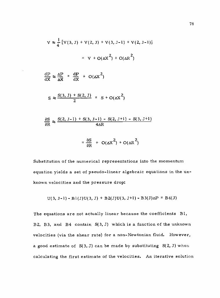
78
1 rV
4LV(3, J) + V(2, J) + V(3, J-1) + V(2,3-1)]
= V + 0(AX 2) + 0( R2)
dP AP _ + O( oX 2)dX AX dX
S(3, J) + S(2, J.)S S + 0(AX
z)
2
as S(2, J-1) + S(3, J-1) - S(2, J+1) - S(3, J+1)aR 4AR
Ras
=8
+ 0( X2) + 0(AR 2)
Substitution of the numerical representations into the momentum
equation yields a set of pseudo-linear algebraic equations in the un-
known velocities and the pressure drop:
U(3, J-1) - B1(J)U(3, J) + B2(J)U(3, 3+1) - B3(J)AP = B4(J)
The equations are not actually linear because the coefficients Bl,
B2, B3, and B4 contain S(3, J) which is a function of the unknown
velocities (via the shear rate) for a non-Newtonian fluid. However,
a good estimate of S(3, J) can be made by substituting S(2, J) when
calculating the first estimate of the velocities. An iterative solution

79
is formed by calculating S(3, J) from the velocities then recalculating
the velocities. Solving for the error in the representation gives a
discretization error of 0(AX 2)+ O(LR2).

80
APPENDIX III
ELIMINATION PROCEDURES FOR SOLVING ENERGYAND MOMENTUM EQUATIONS
Energy Equation
The set of simultaneous linear equations derived from the
energy equation plus boundary conditions when written in matrix
notation is737' = B3
The terms T and B3 as used here are vectors, and B is a
tri-diagonal matrix of coefficients. Since B is tri-diagonal the
solution for the unknown T(3, J) is possible by straight-forward ap-
plication of the Gauss elimination method. Written out explicitly the
set of equations has the following form.
-B1(1)T(3,1)+B2(1)T(3,2) = B3(1)
T(3,1)-B1(2)T(3,2)+B2(2)T(3,3) = B3(2)
T(3,2)-B1(2)T(3,3)+B2(3)T(3,4) = B3(3)
T(3, N-2)-B1(N-1)T(3, N-1)+B2(N-1)T(3, N) = B3(N -11
T(3, N-1)-B1(N)T(3, N) = B3(N)

The elimination procedure is initiated by defining
and
For J > 1
and
Finally the result is
B2(1)a(I) B1(1)
B3(1)13(0= - B1(1).
a(J) = -B2(J)
B1(J) + a(J -1)
B3(J)- p(J-1)P (J) = B1(J) + a(J -1)
T(3, N) = p(N)
81
The other temperatures are then found by back-substitution into the
equation
T(3, J) = p(J) - a(J)T(3, J+1).
Momentum Equation
The set of momentum equations with the integral form of the
continuity equation appended to it may be written as follows (The

82
continuity equation is written first.):
B5(2)R(2)U(3,2)+ . .
-[B1( 2)+1] U(3, 2)+B 2( 2)U(3,
U(3, 2)-B1(3)U(3,
U( 3,
+B5(N-1)R(N-1)U(3, N-1) =1/8
3) -B3(2)AP=134(2)
3)+B2(3)U(3,4) -B3(3)=7134(3)
3)- B 1 (4)U( 3,4')+B 2(4 )U( 3,4)-B 3(4W134(4)
U(3,N-3)-B1(N-2)U(3,N-2)+B2(N-2)U(3,N-1)-B3(N-2),B4(N-2,
U(3,N- 2)4 B1(N-1)+B2(N-1)] U(3, N-1) -B3(N-1)AP=B4(N-1)
Application of the elimination method in this case is not so straight-
forward as it is in solving for temperatures. Not all elimination
methods work because of loss of significant figures, and iterative
methods give only fair results while using tremendous amounts of
computer time. The following elimination method solves the equa-
tions far better than iterative methods while using comparatively
little computer time.
The procedure actually used redefines the set of B4(J) so
that one may solve for
AU(J) = U(3, J) - U(Z, J)
instead of solving for U(3, J).

83
The set of equations to be solved with that change incorporated is as
follows:
B5(2)R(2)AU(2)+ . . +B5(N-1)R(N-1)AU(N-1) = 0
-D31(2)+11 AU(2)+B2(2)AU(3) -B3(2)AP=B4(2)
AU( 2)-B 1( 3)AU( 3)+B 2( 3)6.1.1(4) -B3( 3)AP= B4( 3)
AU( 3)- B1 (4)AU(4)+B 2(4)AU( 5) -B 3(4),6P= B4(4)
AU(N-3)-B1(N-2)AU(N-2)+B2(N-2)AU(N-1) - B3(N-2),6P=B4(N-2)
AU(N-2)-[B1(N-1)+B2(N-1)]AU(N-1)-B3(N-1)AFB4(N-1)
The elimination procedure is started by defining a set of numbers
obtained by dividing the continuity equation by the leading element:
for
and
Q(J)B5(J)R(J)
B5(2)R(2)
N - 1
a(N) = 0.
The first momentum equation is then divided by the negative of its
first element:
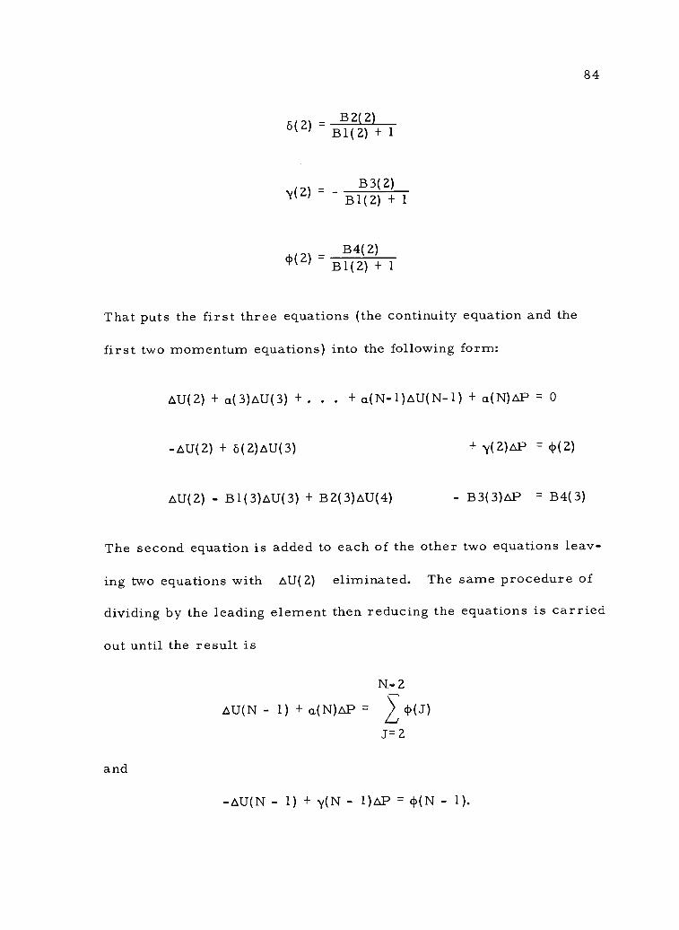
84
SB2(2)
-"" B1(2) + 1
B3(2)y(2) -
B1(2) + 1
B4(2)c)(2)
B1(2) + 1
That puts the first three equations (the continuity equation and the
first two momentum equations) into the following form:
AU(2) + a(3)AU(3) + . . . + a(N-1)AU(N-1) + a(N)LP = 0
-AU(2) + 6(2)AU(3) "Y(2)AP (OM
AU( 2) - B1( 3)AU( 3) + B2( 3)AU(4) - B3(3)AP = B4(3)
The second equation is added to each of the other two equations leav-
ing two equations with AU(2) eliminated. The same procedure of
dividing by the leading element then reducing the equations is carried
out until the result is
and
AU(N - 1) + a(N)AP = 4)(J)
J=2
-AU(N - 1) + N(N - OAP = ct)(N - 1).

85
Then AP can be evaluated:
J=2AP a(N) + .y(N - 1)
Back-substitution for the AU(J) is then begun:
and
for
AU(N - 1) = y(N - 1)AP - (I)(N - 1)
AU(J) = N(J)AP + 5(J)AU(J + 1) - 4(J)
N - J 2
The set of velocities U(3, J) is then obtained by substitution into
U(3, J) = AU(J) + U(2, J).

86
APPENDIX IV
FORTRAN PROGRAM FOR PIPE FLOW PROBLEM
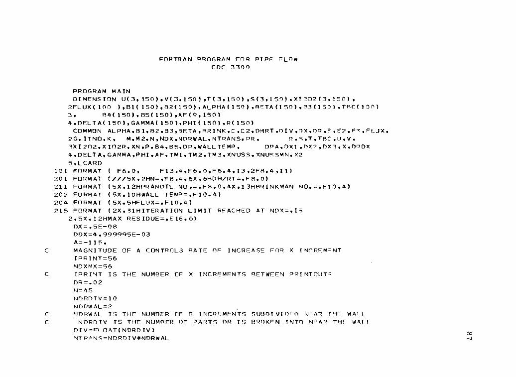
FORTRAN PROGRAM FOR PIPE FLOWCDC 3300
PROGRAM MAINDIMENSION U(39 150) .V( 39150 ) .T( 39150) .S(39150)0(1202(39150)92FLUX( 100 )961(150).82(150),ALPHA(150)9BETA(150),B3(151).TBC(100)3, B4(150).85(150)9AF(99150)49DFLTA(150),GAMMA(150)9PHI(150).R(150)COMMON ALPHAII81.82.83.BETA9RRINK,C,C29DHRT9DIV9DX,DR.E.E29E79ELJX-92G,ITNO.K. M9M2.N.NDX.NDRWAL9NTRANS,PR, R.S.T9TBC.U.V,3XI202.XIO2R.XN.P.B4.859DP.WALLTEMP. DPA.DX19DX29DX39X9DPDX49DELTA.GAMMA9PHIsAF.TM19TM29TM3sXNUSS.XNUSSMN9X259LCARD
101 FORMAT ( F6.0, F13.49E6.09E6.4913.2E8.401)201 FORMAT (///5)(92HN=9F8.416X96HDH/RT=.E8.0)211 FORMAT (5)(.12HPRANDTL NO.=.F8.094X913HBRINKMAN NO.=9E10.4)202 FORMAT (5)(910HWALL TEMP=9F10.4)204 FORMAT (5X95HFLUX=9F10.4)215 FORMAT (2)(931HITERATION LIMIT REACHED AT NDX=05
295X912HMAX RESIDUE=9E16.6)DX=.5F-08DDX=4.999995E-03A=-115.
C MAGNITUDE OF A CONTROLS RATE OF INCREASE FOR X INC-REM7=NTIPRINT=56NDXMX=56
C IPRINT IS THE NUMBER OF X INCREMENTS BETWEEN PRINTOUTSDR=.02N=45NDRDIV=10NDRWAL=2
C NDRWAL IS THE NUMBER OF R INCREMENTS SUBDIVIDED N=A? THE WALLC NORDIV IS THE NUMBER OF PARTS DR IS BROKEN INTO NEAR THE WALL
DIV=FLOAT(NDRDIV)NTRANS=NDRDIV*NDRWAL

ITNMX=20G=.001
75 READ 101,PR, BRINK.OHRT0XN.K.W1,W2.LCARDITFAIL=0
C K FQ 1 MEANS FLUX BOUNDC K FQ 2 MEANS TEMP BOUND
PRINT 201.XN.DHRTPRINT 211,PR,BRINK
C BOUND COND BELOW IS FOR UNIFORM FLUX OR TEMPIF (K .EQ. 1)4,5
4 PRINT 204.W1DO 6 J=1,NDXMX
6 FLUX(J)=W1GO TO 7
5 PRINT 202.W1DO 10 J=1.NDXMX
10 TBC(J)=W17 CONTINUE
C=(3.*X144-1.)/(XN1-1.)E=(XNA-1.)/XNC2=(3.*XN-1-1.)/XNF2=1./XNE3=(XN-140/26X102R=4.*C2**2M=N-1M2=N-2NPRINT=1NDX=0X=0.X2=0.DPL=0.ITNO=0CALL INLTCOND0X 1 =7X
DX2=DXOX3=0X

X=DX/2.NDX=1RESLAST=1000.
35 CALL TEMPCALCCALL SCALC
36 CALL UANDVITNO=ITN0+1CALL SCALCRESMX=0.DO 43 3=2,MVISC=(S(311.) )+S(211,) ))/2.DUDR=(U(2,J-1)-U(2,3+1))/AF(4,J)IF (..) .EQ. 2)39,40
39 DSDR=(S( 3,2)-S(3,3)+S(2,2)-S(2,3))*1IV/(2.*DR)GO TO 41
40 DSDR=(S(31,..)-1)-S(3,J+1)+S(2,..)-1)-S(2,J+1))/(2.*AF(4,J))41 RES=ABSIVISC*IU(3,J-1)+U(1,J-1)+B2(J)*(U(3,i+1)+U(1,J+1))
2- AF( 1, J ) *(U(3,J) +U(1,J))) /(2. *AF(2,J))3+VISC/AF(9,J)*DUDR+DSDR*DUDR-2.*DPA/(DX2+0X3)4-U(2,J)*(U(3,J)-U(1,J))/(DX2+DX3)/PR5-(V(3,J)+V(2,J)+V(30J-1)+V(2,J-1))/4.*DUDR/RR)IF (RES .GT. RESMX)47,43
47 RESMX=RES43 CONTINUE
IF (RESMX *LT. .5 .AND. RESLAST .LT. .9P.AND. RESMX .LE. RESLAST)42,51
51 RESLAST=RESMXIF (ITNO .LT. ITNMX)36,52
52 PRINT 215,NDX,RESMXIF (ITFAIL .GE. 1)45950
SC ITFAIL=ITFAIL+142 CONTINUE
TM3=U(3,2)*T(312)*R(2)*B5(2)*2.+IU(3,2)*T(3,2)*R(2)2+U(313)*T(3,3)*R(3))#(95(2)+95(3))DO Sri J=3,MQ=(F9(J-1)+95(J))/2.

B=(85(.14-1)+85(J))/2.ZI=U(39J-1)*R(J-1)*T(39J-1)Z2=U(39,1 )*R(J ) *T(3,J )
73=U(31J+1)*R(J+1)*T(39J+1)ZA=(B*(Z1-Z2)+0*(Z3-72))/(0**2*-8+9**2*0)ZB=(B*#2*(Z2-Z1)+Q**2*(Z3-Z2))/(0**2*B+B**2*0)TM3=TM3 +(ZA/3.*(B**34-Q**3)+78/2.*(B**7-0**2)+72*(0+) *4.
95 CONTINUEC NUSSELT NO CALC BELOW IS FOR NO VISCOUS DISSIPATION
IF (NDX .E04, 1)96,9797 NM1=NDX-1
IF (K .EC). 1)5395453 WALLTEMP=(T(2.1)+T(292))/2.
XNUSS=FLUX(NM1) /(WALLTFMP-TM2)220 FORMAT ( /2X,5HAT X=9E16.6.2X915HNUSSFLT NUMBER=9E15.692X
2910HMFAN TEMP=11F16.692X910HWALL TEMP=9E16.6)PRINT 220,X2,XNUSS,TM2,WALLTEMPGO TO 96
54 CONTINUEXNUSS= ((DX3*TM2+0)(2*TM3)/(DX34-DX2)-(DX2*TM14-DX1*TM2)
2/((1X2+0X1))/(DX2*(TBC( NM1)-TM2))/4.C CALC FOR MEAN NUSS NO FOR UNIFORM WALL TEMP ONLY
XNUSSMN= ALOG((TBC( NM1)-1.)/(TFIC( NM1)-TM2))/(4.*X?)217 FORMAT ( /2X,5HAT X=9F16.692X.15HNUSSFLT NUMBFR=,E16.692X
2910HMEAN TEMP=9E16.6,2X.20HMEAN NUSSELT NUM9FR=9715.6)PRINT 2179X2.XNUSS9TM29XNUSSMN
96 CONTINUEIF (NDX .GE. 2)500,501
500 DELTP=2.*DPL/(DX14-DX2)502 FORMAT (2)(92HP=9E16.692X93HDP=1E16.6.92X
PRINT 5029P9DPL,DELTP501 CONTINUE
DPL=DPAP=P+DPAIF (NOX .E0. IPRINT*NPRINT)22,23
22 CALL OUTPUT
6 DP/DX=9-1c.'11
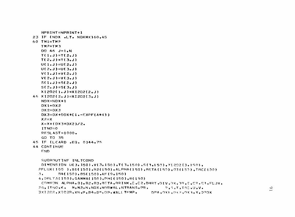
NPRINT=NPRINT+123 IF (NDX .LT. NDXMX)60,4560 TM1 =TM2
TM2=TM3DO 46 J=1,NT(1,J)=T(2,J)T(2,J)=T(3,J)U( 1,J)=0(211.9)U(2,J)=U(3,J)V(1,J)=V(2..1)V(2,J)=V(3,J)S( 1,J)= S(2sJ)S(2,J)=5(3,J)XI202(1,J)=XI202(2.J)
46 X1202(2,J)=X1202(3..1)NDX=NDX+1DX1=DX2DX2=DX3DX3=DX+DDX#(1.FXPF(A*X))X2=XX=X+(DX3+DX2)12.ITNO=0RESLAST=1000.GO TO 35
45 IF (LCARD .EQ. 0)44,7544 CONTINUE
END
SUBROUTINE INLTCONDDIMENSION U( 3, 150) OR 3,150 ) iT( 3,150) ,S(3,150), XI 202 (3,150),
2FLUX( 100 ).81( 150)482(190),ALRHA(150) ,f3ETA (-15o) ,93 (151 ) ,TBC( 100)3, 134(150),85(150),AF(9,150)4,DFLTA(150),GAMMA(150),PHI(150),R(150)COMM1N ALPHA,B1,132,193,BETAIRPINK,C,C2,DHRTsDIV,OYs7)9.,=72,E3,FLJX.
2G, ITNO,K, M,M2,N,NDX,NDRWAL,NTRANS,PR, D,S,T,TRZ,U,V,3XI2112:,X102R,XN,P,84,85,DP,WALLTFMPs DPA,OX1,OX2,DX3,X,WIDX
49DELTA9GAMMAIIPHIsAFsTM1sTM211TM3sXNUSS,XNUSSMN,X259LCARDDO 1 J=19NV( 1,J) =0.V(29J)=0.V(39J)=0.T(19.3)=1.T(2.3)=1.
1 T(39J)=1.R(1)=.54-0R/DIV/2.DO 2 J=204IF (J NTRANS+1)360,361
360 R(J)=.5(J-1)*DR/DIV+DR/(2.*DIV)95(J)=DR/DIVGO TO 362
361 R(J)=.5NDRWAL*DR(J-1NTRANS)*OR+DR/2.B5(J)=DR
362 U(19J)=C*(1.(2.*R(J))**E1U(2,J)=U(1,J)U(39J)=U(1,J)XI202(1.J)=XIO2R*(2.*R(J))**(2.*F2)X1202(29J)=X1202(19J)XI202(39J)=XI202(19J)ARG2=ABSF(XN-1.)IF (ARG2 .LT. .000001)399
3 S(1,J)=1.GO TO 5
9 IF (XI202(1TJ) *LT. G*X102R)7947 S(19J)=G**F3GO To 5
4 S(1,J)=(2.*R(J))**(1.E2)S(29J)=S(19J)S(3,J)=S( 1,J)
2 CONTINUE05(1) =95(2)R5(N)=95(M)

R(N)=R(M)S(IsN)=S(1.M)S(2.14)=S(1,M)S(3.N)=S(1.M)U(141)=U(1,2)U(11N)= U(1.M)0(211)=U(1.2)0(311)=U(1,2)U(2.N)=U(1,M)U(3.N)=U(1.M)UAVG=2.*U(3.2)*R(2)*B5(2)+W(3.2)*R(2)+U(3.3)*R(3))*(39(2)+35(3))DO 620 J=3.MA=(85(J-1)+65(J) )/2.B=(85(j+1)+85(J))/2.Z1=U(3.3-1)*R(J-1)Z2=0(3.3 )*R(J )
73=U(3.J+1)*R(J4-1)ZA=03*(ZIZ2)+A*(Z3Z2))/(A**2*84-8**2*A)ZB=(B**2*(Z2Z1)+A**2*(2:3Z2))/(A**2*B+8**2*A)UAVG=UAVG+(ZA/3.*(B**3+A**3)+Z8/2.*(B**2A*A1/42) 4-7_2*(4+9))*A.
620 CONTINUE221 FORMAT (5)(.17HAVERAGE VELOCITY=.F20.10)
PRINT 221,UAVGTM1=1.TM2=1.TM3=1.DPDX=8.*C2
314 FORMAT (5X16HDP/DX=.E15.6)PRINT 314,DPDXP=0.DO 600 J=2.MIF (J.LE. NTRANS)601,602
601 AF(1,J) =2.AF(2,J)=(DR/DIV)**2AF(3.J)=DR/DIVAF(4.J)=2.*DR/DIV

AF(5,J)=.5AF(69J)=.5AF(79J)=.5AF(8,J)=.5AF(9,J)=R(J)82(J)=11.IF (J .E04. 2)611,600
611 AF(2,J)=AF(2,,J)*3./4.AF(39J)=AF(3,J)*3./4.GO TO 600
602 IF (J *GE. NTRANS+3)603,604603 AF(ItJ)=2*
AF(2,J)=DR**2AF(39J)=DRAF(41J)=2.43RAF(5,J)=.5AF(6sJ)=.5AF(7,J)=.5AF(8,J)=.5AF(91J)=R(J)82(J)=1.GO TO 600
604 IF (J oF_O. NTRANS+1)609,610609 AF(1,J)=(OIV+34) /(DIV4.1.)
AF(2,J)=(OIV+340*(OR/DIV) #442/4.AF(3,J)=DR/DIVAF(4,J)=(DIN14-3.)#DR/(2.*DIV)AF(5,J)=.5AF(6,J) =.5AF(79J)=1./(DIV4-1-.)AF(8,J)=DIV/(DIV+1.)AF(9,J)=(R(J+1)+R(J-1))/2.92(J)=2./(DIV+1.)IF (J .EQ. 2)612,600
612 AF(2,J)=AF(29J)*3./4.AF(3,J)=AF(3,J)*3./4.
GO TO 600610 AF(11.1)=(3.4,DIV+1.)/(2**DIV)
AF(2,J)=(3.*01V+1.)*(O1V+110*(OR/DIV)*#2/B.AF(3,J)=(DIV-4-1.)10DR/(2.*DIV)AF(41.1)=(3.*DIV+1) MR/(2.*DIV)AF(5-0.1)=1./(OIV+1.)AF(6,J)= DIV /(DIV +1.)AF(7,J) =.5AF(B,J)=.5AF(9.J)=(R(J+1)+R(J-1))/2.B2(J)=(OIV+1.)/(2**OIV)
600 CONTINUERETURNEND
SUBROUTINE TEMPCALCDIMENSION U(39150),V1391501sT(3,150),S(3,150),X1202(3o150),
2FLUX(100 )11B1(150),B2(150)sALRHA( 150),BETA(150),B3(150),T9C(11n)3, 84(150)985(150),AF(9,150)4,DELTA(150),GAMMA(150),PHI(150),R(150)COMMON ALRHA.81,82983,8ETA,BRINK,CsC2s0HRT,OIV90X9DR,=1E2,F3,FLJX,,2G,ITNO,K, M,M2,NIINDX,NORWAL,NTRANS,RR, R,S,T,TBC$U4V,3XI2020C102R1IXN,P,B4,854DPIWALLTEMR, DPA,DX1,0X211DX3,X,020X49DELTAIIGAMMA,PHI,AF,TM1sTM2sTM3,XNUSS,XNUSSMN,X2S,LCARD01=0X2+(DX1+0X3)/2.DO 92 J=2,MR1=AF(111J)R2=AF(2sJ)R4=AF(39J)RAD=AFI9.J/B1(.1)=R1+R2 *(U(1,J)+U(2,J))/D1B3(J)=R4 *(V(21,J)+V(2,J-1))*(T(2-e,1--1)T(21J-4-1))/2.
2-2.*R2*BRINK*S(2sJ-1)*XI202(2,J-1)T(19J-1)-132(J)*T(liJ4-1)3 +(R1 P2 *(U(1,J) +U(2,..1))/O1 )*T(I,J) cn
4R4/RAD *(T(2,J-1)T(2,J+1))

92 CONTINUEC T(3*J-1)--.61(J)*T(3*J)+82(J)*T(3.J+1)=433(J)
IF (K .EQ. 1)50,5151 81(1)=-1*
82(1)=1.83(1)=2**TBC NDX/GO TO 52
50 81(1) =-1.R2(1)=-1.83(11=DR/DIV *FLUX(NDX)
52 CONTINUEBl(N)=1*B2(N) =0.83(N1=0.ALPHA(1)=-(B2(1)/81(1))8ETA(1)=-(B3(1)/B1(1))DO 93 3=2*N4LPH4(J)=B2(J)/(-81(J)-ALPHA(J-1))
93 BET4(J)=(B3(J)-BETA(J-1)1/(-81(J)-ALPHA(.1-1))T(3,N)=BETA(N)DO 94 J=1*MNMJ=N-J
94 T(3, NMJ) =BETA (NMJ)- ALPHA(NMJ) *T(3,NMJ +1)IF (NDX .EQ. 3 .OR. NDX .50. 4)30.31
30 IF (K *EQ. 2)32,3132 SLOPE=ABS(T(3,2)-TOC( NDX))/(DR/3IV/2.)
SLPLST=SLOPEDO 34 J=304SLOPE=ABS(T(3*J)-T8C( NDX))/ (.5 -R(J))IF (SLOPE .LE. SLPLST)38,39
39 SLPLST=SLOPE34 CONTINUE38 J=J*1
ZREF=.5-R(J)TREF=T(3,J)-TBC(NDX)J2=J-1

DO 43 J=2,J243 T(3,J)=TBC(NDX)+(95R(J))/Z FF*TRFF
T(391)=29*TBC( NDX) T(3,2)31 CONTINUE
RETURNEND
SUBROUTINE SCALCDIMENSION U(3,150)11V(3*150)11T(39150)95(39150)9X1202(3,150),2FLUX(100 ),B1(150),B2(150).ALPHA(150)99ETA(150)983(153),T8C(100)3, B4(150)1,85(150),AF(9,15014,DELTA(150),GAMMA(15()),PHI(150),R(150)COMMON ALRHAsB1e8298398ETA9BRINK9C9C29DHRT,DIVIIDX,DR,E9F7sE39FLjX,2G9ITNO9K, MirM29NsNDX9NDRWALIINTRANS,PR, R,S,T,TBC,U,V,3X12020(102R9XN9P984985,DP9WALLTEMPs DPA,DX19DX29DX3IpX,DOX49DELTAIIGAMMA,PHI9AF,TM19TM29TM39XNUSS9XNUSSMN,X259LCARDIF (ITN° .EQ. 0)31,16
31 on 32 J=20432 S(3,J)=S(29J)#EXPF(DHRT*(19/T(39J )-1./T(29J ))*XN)
GO TO 1516 1=3
DO 8 J=29MIF (J *LT. NTRANS+1)3839384
383 R9= DIV /(2. *DR)GO TO 385
384 IF (J .GE. NTRANS +3)386,387386 R9=1./(2.*DR)
GO TO 385387 IF (J .EQ. NTRANS+1)3889389388 R9=2.*DIV/(DRA(DIV+3.))
GO To 385389 R9=204DTVI(DR*(3-.*DIV4-1.) )335 04=B9*(U(19J+1)1-U(I-19J+1)U(19J-1)U(I-1,J-1))/''.
XI202(I,J)=D4**2IF (XI202(19J) .LT. G*XIO2R)28929

28 S( I,J) =(EXPF(DHRT #( 1./T( I,J )-1.)*XN))*G**E3GO TO 8
29 S(1,J)=.(EXPF(OHRTA(1./T(I,J )-1.)40(N))*(XI202(I,J)/XIn2R)**E38 CONTINUE15 CONTINUE
S(304)=S(3,M)RETURNEND
SUBROUTINE UANDVDIMENSION U(3o150),V(3,150),T(3,150),S(31,150)0(12112(3,150).
2FLUX(100 ),B1(150)*R2( 150),ALPHA(150),BETA(150),B3(15D),T9C(100)3, 84(150),B5(150),AF(9.,150)4,DELTA(150),GAMMA(150),PHI(15()),R(150)COMMON ALPHA,B1,82,83,BETA,BRINK,C,C2,DHRT,DIVIDIX*DR.=,,E2,73,FLiXil2G,ITNOsKs M.M2,NioNDX,NDRWALIINTRANS:PR,3x1202,x1o2R.xN,P,84,85,DP.wALLTEmp, OPA,OXI,OX2,DX30(1090X4,DELTA,GAMMA,PHI,AF,TMI,TM2,TM3,XNUSS,XNUSSMN*X25,LCARDD1=(DX24-DX3)/2.DO 18 J=2,MR1=AF(1,j)R2=AF(29J)R3=AF(3,J)RA=AF(A,J)R5=AF(29J)/PRRAD=AF(99J)IF (J .E0. 2)615,616
615 DSDR=(S(3,2)S(3,3)+S(242)S(2 3))*DIV/(2.*DR)GO Ti) 619
616 DSOR=(S(3,J-1)S(3,J+1)+S(2,J-1)-5(29J+11)/(2.*R4)619 VISC=(S(211.1 )+S(3,J ))/2.
VEL=(V(311J)+V(2,J)+V(3,J-1)41-V(29J-1))/4,DUDR=(U(2,J-1)-0(2,J4-1))/AF(4.J)81(J)=R1+R5*U(2,J)/(VISC*D1)B3(J)=2.44R2/(VISCAD1)
B4(J) =2. *R5 *VEL*DUDR/VISC-2.21J)#DUD9/RAD2-2,*AF(2,J)*DSDR*DUDR/VISC3-U(1,..1-1)+1RI-R5*U(2,J)/( VISC#D1))*U(1,J)-82(3)*U(1.J+/)4-U( 29J-1)-11-81(J)*U(2,J)-82(J)*U12,J+1)
18 CONTINUEC (U(3...1-1)-U(21J-1))-81(J)*(0(3,J)-U(2.J))+82(,1)*(U(31J+1)-C U12,J4-11)-133(J)*DPA=84(J)
DO 910 J=39M910 ALPHA(J)=85(J)*R(J)/(B5(2)*RI2/)
ALPHA(N) =0.PSI=0.DELTA(2)=82(2)/(81(2)+1.)GAMMA(2)=-83(2)/(81(2)+1.)PH1(2)=84(2)/(E31(2)+1.)DO 911 J=3,M2AD=ALPHA(J)i-DELTA(J-1)BD=81(J)-DELTA(J-1)DO 912 J1=304
912 ALPHA(J1)= ALPHA(J1) /ADALPHA(N)=(ALPHA(N)+GAMMA(J-1))/ADPSI=(PSI+PHI(J-1))/ADDELTA(J)=82(J)/BDGAMMA(J)=IGAMMA(J-1)-83(J))/8DPHI(J)=PHI(J-1)/804-84(J)/8D
911 PHI(J)=PHI(J-1) /8D+84(J)/80AD=ALPHA(M)+DELTA(M2)8D=I81(M)-82(M))-DELTA1M21ALPHAIN1=IALPHA(N)+GAMMA(M2))/ADPSI=( PSI+PHI(M2))/ADGAMMA(M)=IGAMMA(M2)-83(M)1/8DPHI(M)=PHI(M2) /8D+84(M)/80DELTA(M)=0.DIVS= ALPHA(N) +GAMMA(M)DPA= PHI(M)/DIVS+PSI/DIVS8ETA(M)=DPA*GAMMAIM1-PHI(M)
C IN SVANDU BETA(J) EQUALS U(71.J)-U(2,J)

U(3,M)=U(29M)+BETA(M)00 913 J=2042NMJ=NJNMP=NM,04-1BFTA(NMJ)=GAMMA(NMJ)AlcDPAIVDELTA(NMJ)*BETA(NMP)PHI(NMJ)
913 U(3,NMJ) =U(2,NMJ)-1-BETA(NMJ)U(3,1)=U(3,2)U(3iN)= U(3,M)V(3,1)=0.V(3,M)=0.DO 650 J=2,M2Z1=AF(5,J),W(J)+AF(6,J)*R(J-1)Z2=AF(7,j)*R(j+1)+AF(8sJ)4R(J)
650 V(3,J)=Z1/Z2*V(3,J-1)+R(J)*B5(J)/72*BETA(J)/0X3RETURNEND
SUBROUTINE OUTPUTDIMENSION U(31150)0/(3,150),T(3.150)*S(3,150),X120?(3,150),
2FLUX(100 )1181(150)*B2(150),ALPHA(150),8FTA(150),83(151),TBC(100)3, 84(150),85(150),AF(9,150)4,DELTA(150),GAMMA(150),PHI(150),R(150)COMMON ALPHA,B1,82,839BETA,BRINK,C,C2,D1-tRTOIV,DX,DR,F,E2,E3,FLJX
PG,ITNO,K, M,M2sNsNDX,NDRWAL,NTRANSIPR, R,S,T,TBC,U,V,3x1(202,xio2R,xN.P,B4,(35,DP.wALLTEmP, oPA.nx1,ox2.Dx3,x,D.Dx4,DELTA,GAMMA.PHIIAF,TM19TM2,TM3,XNUSS,XNUSSMN,X?5,LCARD
206 FORMAT (2X,14,5E22.10)207 FORMAT (2X9149E2210,22X,F22.10)208 FORMAT (/5XIIHJI10X01HU*21X91HV,2IX,1HT921X,145.?0X041121?)210 FORMAT (/5X,SHITNO=II3)212 FORMAT (5X94HNDX=,,I4,10X,2HX=.E12.3,10X,3HDX=4E1?.3)213 FORMAT (5X,9HUAVERAGE=IF20.10)214 FORMAT (5Xs9HTAVERAGE=IF14.6)?16 FORMAT (5Xt5HP(3)=,E15.6,5X,10HP(3)P(2)=sF15.6) O
PRINI 208 O

J=1PRINT 206.J.U(3.1).V(31.1)IpT(3,01)DO 70 J=2,M
70 PRINT 206ioJsU(31,J),V(3,J),T(3,J),S(31J )9XI2n2(3,j)PRINT 207,N,U(31oN),T(3sN)UAVG=2.*U(3,2)*R(2)*R5(2)+(U(3.2)*R(2)+0(3.3)*R(3))*(35(2)+S(3))DO 21 J=304A=035(J-1)+85(J))1.2.B=(85(J+1)+85(J))/2.Z1=U(3,J-1)*R(J-1)Z2=U(3.J )*R(JZ3=U(3,J+1)*R(J+1)ZA=03*(71Z2)+A*(73Z2))/(A**2*84-8**2*A)7.8=(B**2*(22Z1)+A**2*(Z3Z2))/(A**2*B+8**2*A)
21 UAVG=UAVG4.(ZA/3.*(5**34-A**3)+78/2*(82**2A**2)+72*(A4-3) *4PRINT 210,ITNOPRINT 2121INDX,X,DX3PRINT 213.UAVGPRINT 214,TM3PRINT 216.129DPARETURNEND
FINIS

102
APPENDIX V
FORTRAN PROGRAM FOR CHANNEL FLOW PROBLEM

FORTRAN PROGRAM =OR CHANNEL FLOWCDC 3300
PROGRAM MAINDIMENSION 0(3,210)9V(3.210),T(3,210)*S(3,210)eXI202(3.210),
2FLUX(2990)031(210)9-82(210),ALPHA(210),BETA(210),B3(?11),TRC(29 Po)3, 84(210).85(210),AF(4,210)4,DELTA(210),GAMMA(210),PHI(210)COMMON ALPHA.B1s82,839BETA,BRINK,C,C2oDHRTIDIV,DX.0Y,E,E2,F3,FLJX,2G,ITNOsK,L,M.M2sN,NDX,NDYWALIINTRANS,PR,3XI202.XIO2R,XN,P,B4035,DP, DPA,DX1,DX2,DX3sXr0PDX4,DELTAvGAMMA,PHIgAF,TM1,TM2sTM3
101 FORMAT ( F6.0,F8.4,F6.09F6.4,1392E8o4s1392F3.49I1)201 FORMAT (///5Xs2HN=,F8.4,6X,6HDH/RT=IF8.0)211 FORMAT (5X,12HPRANDTL NO.= ,F8.O,4X,I3HBRINKMAN NO.=eF10.4)202 FORMAT (5X912HAT Y=0, TBC=sE10.4)203 FORMAT (5X,12HAT Y=1, TBC= ,F10.4)204 FORMAT (5X,13HAT Y=0, FLUX=,F10.4)205 FORMAT (5X,13HAT Y=1. FLUX=.F10.4)215 FORMAT (2X,31HITERATION LIMIT REACHED AT NOX=,I5
2,5X1112HMAX RESIDUE=,E16.6)DX=5.E-08DDX=4.99995E-03A=-115.NDXMX=60IPRINT=60
C IPRINT IS THE NUMBER OF X INCREMENTS BETWEEN PRINTnuTsDY=.02N=88NOYOIV=10NDYWAL=2
C NDYOIV IS THE NUMBER OF PARTS DY IS BROKEN INTO NEAR THF WALLC NOYWAL IS THE NUMBER OF Y INCREMENTS SUBDIVIDED N7AR THE WALL
DIV=FLOAT(NDYDIV)NTPANS= NDYDIV *NDYWAL
ITNMX=20G=.001
75 READ 101,PR, BRINK.DHRT.XN.K.W1042L,W3,W4,LCADITFAIL=0
C K EQ 1 MEANS FLUX BOUND AT y=pC K EQ 2 MEANS TEMP BOUND AT Y=0C L EQ 1 MEANS FLUX BOUND AT Y=1C L EQ 2 MEANS TEMP BOUND AT Y=1
PRINT 201,XN,DHRTPRINT 211sPR.BRINK
C BOUND COND BELOW IS FOR UNIFORM FLUX OR TEMPIF (K .EQ. 1)4,5
4 PRINT 204,W1DO 6 J=1.NDXMX
6 FLUX(1sJ)=W1GO TO 7
5 PRINT 202,W1DO 10 J=1.NDXMX
10 TBC(1..))=W17 IF (L .EQ. 1)11,1211 PRINT 205,W3
DO 13 J=1.NDXMX13 ELUX(2sJ)=W3
GO TO 312 PRINT 203.W3
DO 15 J= 1,NDXMX15 TBC(2..))=W33 CONTINUE
C NO CHANGES ARE NEEDED PAST HERE WHEN COMP CONDITIONS ARE CHANGEDC=(2.#XN+1.)/(XN+1.)E=(XN44-1-.)/XNC2=(2.*XN+1.)/XNE2=1./XNE3=(XN-1.)/2.XIO2R=4.#C2*C2M=N-1
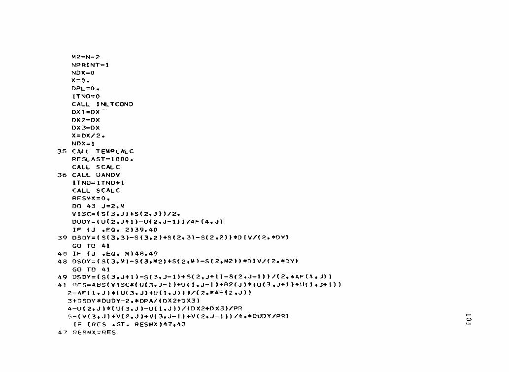
M2=N-2NPRINT=1NDX=0X=0.OPL=0.ITN0=0CALL INLTCONDOX1=DXDX2=DXDX 3=0XX=DX/2.NDX=1
35 CALL TEMPCALCRESLAST=1000.CALL SCALC
36 CALL UANDVITNO=ITN0+1CALL SCALCRFSMX=0.DO 43 J=2,MVISC=(S(3,J)+5(2,J))/2,DUDY=(U(2,J+1)U(2,J-1))/AE(4,J)IF (J .EQ. 2)39,40
39 DSOY=LS(3,3)S(3,2)+S(2,3)-5(2,2))*DIV/(2.*DY)GO TO 41
40 IF (J .E04, M)48,4948 OSDY=(S(3,M)S(3042)+S(2,M)S(2,M2))*DIV/(2,*DY)
GO TO 4149 OSDY=(S(3,J+1)S(3,J-1)+S(2,J+1)S(2,J-1))/(2.*AF(4,J))41 RES=ABS(VISC4c(U(3*J-1)+U(1,J-1)+82(1)*(U(3,J+1)+U(19J+1))
2AF(1,J)*(U(3.J)+U(1,J)))/(2.*AE(2,J))3+DSDY*DUDY-2.*DPA/(DX2+0X3)4U(2,J)*(U(39J)U(1,J))/(DX2+DX3)/PR5(V(3,J)+V(2,J)+V(3,J-1)+V(2,J-1))/4.*DUDY/PR)IF (RES .GT. RESMX)47,43
47 RESMX=RES
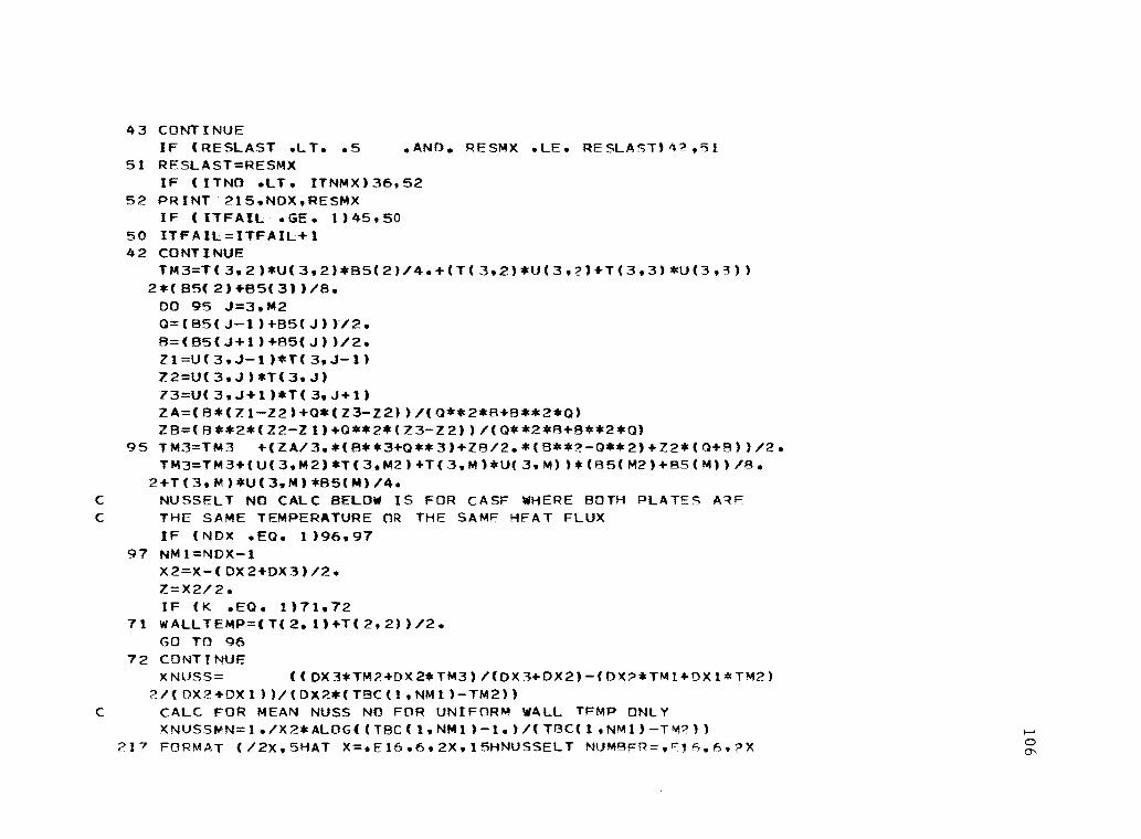
43 CONTINUEIF (RESLAST-4,LT. .5 .AND. RESMX .LE. RESLAST)42,51
51 RFSLAST=RESMXIF (ITNO .LT. ITNMX)36,52
52 PRINT 2150NDX,RESMXIF (ITFAIL .GE. 1)45,50
50 ITFAIL=ITFAIL+142 CONTINUE
TM3=T(3,2)4,U(3,2)#B5(2)/4.+(T(3,2)*U(3,2)+T(3,3)4,U(3,3))2*(85(2)+85(3))/8.DO 95 J=3012O=185(3-1)+B5(3))/2.B=(B5(3+1)+85(J))/2.Z1=U(3,3-1)*T(3,3-1)72=U(3,3)*T(3,3)23=U(3,34-1)*T(3,J+1)ZA=(B*(71Z2)+0*(Z3Z2))/(0**2*B+B**2440)713=(B**2#(72Z1)+40**2*(Z3Z2))/(0**2*B+Bgc#2*())
95 TM3=TM3 +(ZA/3**(B#*3+0*#3)+78/24,*(B**2-0**2)+72*(0+S))/20TM3=TM34-(U(31M2)*T(3,M2)+T(3,M)*U(3,M))*(135(M2)+85(M))/8.2+T(3,M) *U(3,M)*B5(M)/4.
C NUSSELT NO CALC BELOW IS FOR CASE WHERE BOTH PLATES ARFC THE SAME TEMPERATURE OR THE SAME HEAT FLUX
IF (NDX *EC,. 1)96,9797 NM1 =NDX -1
X2=X(0X2+03(3)/2.Z=X2/2.IF (K .E0. 1)71,72
71 WALLTEMP=4T(2,1)+T(2,2))/2.GO TO 95
72 CONTINUEXNUSS= ((DX340-M2+0X2*TM3)/(OX3+00X2)(0X2*TM1+DX11,TM2)2/(DX2+120(1))/(DX2*(TBC(1,NM1)TM2))
C CALC FOR MEAN NUSS NO FOR UNIFORM WALL TEMP ONLYXNUSSMN=1./X2*ALOG((TBC(104M1)-1.)/(TBC(1,NM1)TM2)1
217 FORMAT ( /2X, SHAT X=,F16.6,2X,15HNUSSELT NUMBER=.7) 6.6,2X

2.10HMEAN TEMP=.E16.6.2X.20HMEAN NUSSELT NUMBEP=,E16.6)PRINT 217,2 sXNUSS.TM2.XNUSSMN
96 CONTINUEIF (NDX .GE. 2)500.501
500 DELTP=2.*DPL/(DX1+0)(2)502 FORMAT (2X.2HP=I1F16.6.2X.3HOP=sE16.6.2X.6HDP/DX= .F15.5)
PRINT 502,P,DPL,DELTP501 CONTINUE
DPL=DPAP=P+DPAIF (NDX .EQ. IPRINT *NPRINT)22,23
22 CALL OUTPUTNPR1NT=NPRINT+1
23 IF (NDX .LT. NDXMX)60,4560 TM1=TM2
TM2=TM3DO 46 ..)=1.NT(1,J)=T(2,J)T(2,3)=T(3.3)U(1,J)=U(2...1)U(2.J)=U(3,J)V(1,3)=V(2,J)V(2,3)=V(3,3)S(1.J)=S(2.J)S(2.3)=S(31.))X1202(1.J)=X1202(2,J)
46 X1202(2.J)=X1202(3.J)NOX=NDX+1DX1=DX2DX2=DX3DX3=DX+DDX*(1.EXPF(A*X))X=X+(0X3+DX2)/2.ITNO=0GO TO 35
45 IF (LCARD .E0. 0)44,7544 CONTINUE

ENDSUBROUTINE INLTCONDDIMENSION U(39210),V(3,210)9T(39210)9S(3,210) X1202(39210).
2FLUX(2990)931(210)982(210)9ALPHA(210),BETA(210)9B3(211),TBC(29 90)3, 84(210),B5(210)9AF(49210)49DFLTA(210),GAMMA(210)9RHI(210)COMMON ALPHA9B1982983.3ETA,BRINK9C9C29OHRT9OIV,DX.DYsE,E29E39FLjX,2GsITNO9KoL9M9M29N9NOX9NDYWAL,NTRANS,PR9 S,T,TBC,U,V,3X12029X102R9XN,R,B40359DP, DPA,DX19DX29DX39X9OPDX49DELTA,GAMMA.PHI,AF:TMIsTM29TM3DO 1 J=19NV(19J)=0.V( 3,J) =0.V( 2,J) =0.T(19J)=1.T(39.1)=1.
1 T(29.1)=19DO 2 J=204IF (J .LE. NTRANS+1)360.361
360 Y=(J-1)*DY/DIVDY/(29*DIV)85(J)=DY/DIVGO TO 382
361 IF (J .LE. MNTRANS)3649363364 Y=(NDYWAL+(J-1NTRANS))*DY-95*DY
BS(J)=DYGO TO 362
363 Y=(M2-2*NTRANS+NDYWAL)4,DY+(J-1 2+NTRANS)*DY/DIVDY/(2.*DIV)BS(J)=DY/DIV
362 ARG=ABSF(2.*Y-1.)U(11.1)=C*(1.ARG**E)XI202(1,J ) =XIO2R *ARG * *(2. *E2)XI202(29J )=XI202(19J)XI202(39J ) =XI202(19J)ARG2=ABSF(XN-1.1IF (ARG2 .LT. .000001)3,9
3 S(1,J ) =19

GO TO 59 IF (X1202(1,J ) .LT. G*XIO2R)7,47 S(11,J ) =G * *E3
GO TO 54 S(1,J )= ARG * *(1. E2)5 S(2tJ )=S(1,J)
S(3,J )=S(1,J)2 CONTINUE
85(1)=85(2)85(N) =-435(M)S(104)=S(1,M)S(2,N)=S(21M)S(3.14)=S(3,M)U(1,1)=U(1,2)U(1,N)=U(1tM)DO 651 J=1,11U(2,J)=U(1,J)
651 U(3,J)=U(1,J)UAVG=U(3,2)*55(2)/4.4-(l)(3,2)+U( s3))*(55(3)+55(2))/9.DO 620 J=3,M2A=(85(J-1)+B5(J))/24.B=(135(J4-1)+85(J))J2..71=U(3,3-1)72 =U( 3,J)Z3=U(3,J+1)ZA=(5*(Z1Z2)+A*(Z3Z2))/(4**2*B+8*#2*A)Z5=-(13#*2*(72Z1)+A**2*(Z3Z2))/(A**2*5+5214*2*A)
620 UAVG=UAVG4-(ZA/34.*(6**3+A**3)+ZE)/2.*(134t#2-4**2)+7_2*(A+S))/2.UAVG=UAVG+(U(3vM2)+U(3,M))*(85(M2)+95(M))/8.+U(3,M)#85(M)/4,
221 FORMAT (5)(t17HAVERAGE VELOCITY=9E20.10)PRINT 221,UAVGTM1=1.TM2=1.TM3=1.OPDX=4.*C2
314 FORMAT (5)(t6HDP/DX=1,E15.6)
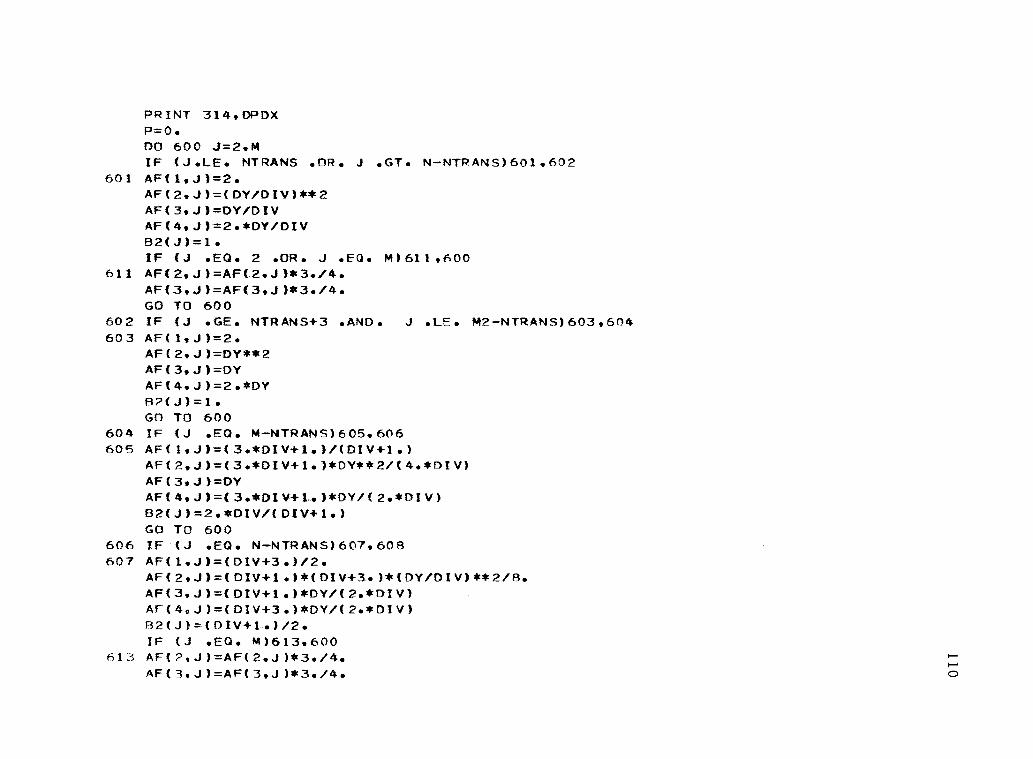
PRINT 314.DPDXP=0.DO 600 J=204IF (J.LE. NTRANS .OR. J .GT. N-NTRANS)601.602
601 AF(1.J)=2.AF(2,J)=(DY/DIV)**2AF(3,J) =DY /DIVAF(4.J)=2.*DY/DIV82(J)=1.IF (J .ED. 2 0R. J .EQ. M)611,600
611 AF(2.J)=AF(2.J)*3./4.AF(3,J)= AF(3,J ) *3./4.GO TO 600
602 IF (J .GE. NTRANS+3 .AND. J .LF. M2-NTRANS)603.604603 AF(1*J) =2.
AF(2,J)=DY*#2AF(3.J)=DYAF(4.J) =2.*DY82(J)=1.GO TO 600
604 IF (J Ea. M-NTRANS)605.606605 AF( 1.J )=( 3.*DIV+1-. )/(DiV+1 )
AF(2.J)=(3.*DIV+1-*/*DY44#2/(4.#DIV)AF(3.J)=DYAF(4.J)=(3.*DIV-4-1.)*DY/(2.*DIV)B2(J)=2.4(DIV/(DIV4.1.)GO TO 600
606 IF (J .E0. N-NTRANS) 607.608607 AF(1.J)=(DIV+3.)/2.
AF(21J)=(DIV4-1.)#(0IV4.3.)*(DY/DIV)**2/8.AF(31J)=(DIV+1.)*DY/(2.*DIV)AF(49J)=(DIV+3.)*DY/(2.*DIV)R2(J)=(DIV+14) /2.IF (J .EQ. M)613.600
613 AF(2.J3=AF(2.J)4(3./4.AF(3,J)=AF(31J)*3./4.

GO TO 600608 IF (J .E0. NTRANS+1) 609,610609 AF(1,J)= (DIV +3.) /(DIV +1.)
AF(2,J)=(01V+3.)*(0Y/DIV)**2/4.AF(3,J)=DY/DIVAF(4,J)=(DIV+3.)*DY/(2,*DIV)82(J)=2./(DIV4-1-4)IF (J 2)612,600
612 AF(2IJ)=AF(2,J)*3,/4.AF(3,J)=AF(3,J)*3./4.GO TO 600
610 AF(1,J)=(3.*DIV#1.)/(2.*DIV)AF(21J)=(3.44DIVM)*(DIV+1-.)*(DY/DIV)**2.18.AF(3,J)=(DIV4-1-,)*DY/(2.*DIV)AF(4,J)=-(3.*DIV+1-.)*DY/(2.*DIV)82(J)=(DIV+1,),(2.*DIV)
600 CONTINUERETURNENDSUBROUTINE TEMPCALCDIMENSION U(3,210),V(3,210),T(3,210),S(3,210),X1202(3,210),2FLUX(2190),B1(210),B2(210),ALPHA(210),RETA(210),B3(211),T8C(2, gO)3, 84(210),85(210),AF(4,210)4,DELTA(210),GAMMA(210),PHI(210)COMMON ALPHA,B1,82,83,BETA,BRINK,C,C2iinHRT,DIV,OX,DY.E,E2,E1,FLJX.2GsITNOIK,L.MtM2,NINDX,NDYWAL.NTRANS,PRs StT,TBCsUoVs3XI2020(IO2RO(N,P,B4,85,DP, DPA,DX1,DX2,DX3,X,ORDX4,DELTA,GAMMAsPHIsAF,TM/sTM2,TM3D1 =DX2 +( OX1 +DX3) /2.DO 92 J =2.MR1=AF(1,J)P2=AF(2,J)RA=AF(3,J)Bl(J)=R1+R2 *(U(1,J)+U(2,J))/01R3(J)=R4 *(V(2sJ)+V(2,J-1))*(T(2,J+1)T(2,J-1))/2,
*R2*F3RINK*S(29,1 )*XI 202 ( ) ( 1 ) 82 ( J *T( 1 , J+1 )

3+(R1 R2 *(U(1,J) +U(2,J)) /D1 )*T(19J)92 CONTINUE
C T(39J-1)-61(J)4eT(39J)+82(J)*T(39J+1)=193(J)IF (K .E0. 1)50,51
51 B1(1)=-1.82(1)=1.83(1)=2**TBC(1,NDX)GO TO 52
50 B1(1)=-1.52(t)=I.B3(1)=DY/DIV *FLUX(19NDX)
52 IF (L 9E0. 1)5395454 B1(N)=-1.
B2(N)=0.83(N)=2.*TBC (2sNDX)GO TO 55
53 81(N)=1:52(N)=0,0B3(N) = (DY /DIV *FLUX(29NDX))
55 CONTINUEALPHA(1)=(52(1)/B1(1))BETA(1)=(83(1)/B1(1))DO 93 J=29NALPHA(3)=52(J)/(-51(J)ALPH4(J-1))
93 BETA(J)=(53(J)BETA(J-1))/(-51(J)ALPHA() -1))T(39N)=9ETA(N)DO 94 J=19MNMJ=NJ
94 T(39NMj)=BETA(NMJ)ALPHA(NMJ)4(T(3,NMJ+1)IF (NOX .EQ. 3 .OR. NDX ,EQ. 4)30,31
30 IF (K 9E0. 2)32,3332 SLOPF=ABS(T(3,2)TBC(1,NDX))/(DY/DIV/2.)
SLPLST=SLOPENSTOP=N/2DO 34 J=3,NSTOPIF () .LE.NTRANS+1)35936

35 Y=(J-1)*DY/DIVDY/(2414DIV)GO TO 37
36 Y=(NDYWAL-4(J-1NTRANS))*DY.5*DY37 SLOPE=ABS(T(3,J)TBC(IsNDX))/Y
IF (SLOPE .LE. SLPLST)38,3939 SLPLST=SLOPE34 CONTINUE38 J=JI
IF (J .LEoNTRANS+1)40.4140 Y=(J-1)#DY/DIVDY/(2.4,DIV)
GO TO 4241 Y=(NDYWAL4-(J-1NTRANS))*DY-08*DY42 YREF=Y
TREF=T(3,J)TBC(19NDX)J2 =J -1
DO 43 J=2,J2IF (J .LE. NTRANS+1)44,45
44 Y=(J-1)*DY/DIVDY/(2.*DIV)GO TO 43
45 Y=(NDYWAL+(JINTRANS))*DY*5*DY43 T(3,J)=T8C(1,NDX)+WYREF*TREF
T(391)=2.*T8C(1,NDX)T(3,2)33 IF (L .EO. 2)46 3146 SLOPE=A8S(T(3,M)T8C(2INDX))/(DY/DIV/2.)
SLPLST=SLOPENSTOP=N/2DO 48 J=3,NSTOPNMJ=NJ+IIF (J .LE. NTRANS+1)60961
60 Y=(J-1)*DY/DIVDY/(2.4,DIV)GO TO 62
61 Y=(NDYW4L+(JINTRANS))*DY5*DY62 SLOPE=A8S(T(3.NMJ)TBC(29NDX))/Y
IF (SLOPE .LE. SLPLST)63,6464 SLPLST=SLOPE4P CONTINUE

63 J=J-1IF (J NTRANS+1)65,66
65 Y=(J-1)*DY/DIVDY/(2.*DIV)GO TO 67
66 Y=(NDYWAL+(J-1NTRANS))*DY.5*DY67 YREF=Y
NMJ=NJ4-1TREF=T(3,NMJ)T8C(2,NDX)J2=J-1DO 68 J=2,J2NMJ=NJ4-1IF (J .LE. NTRANS+1)69,70
69 Y=(J-1)*DY/DIVDY/(24.*DIV)GO TO 68
70 Y=(NDYWAL+(J-1NTRANS))#DY.5*DY68 T(31NMJ)=TBC(2,NOX)41-Y/YREF#TREF
T(3:N)=2.*TBC(2,NDX)T(3,M)31 CONTINUE
RETURNENDSUBROUTINE UANOVDIMENSION U(3,210),V(3s210)*T(3,210),S(3,210),XI202(3,210),2FLUX(2,90),81(210)*B2(210),ALPHA(210),BETA(210),B3(211),TBC(2,3, 84(210),85(210),AF(4,210)4,DELTA(210),GAMMA(210)sPHI(210)COMMON ALPHA,B1982133.9ETA,BRINKsC*C2,DHRTIDIV,DX,DY,E,E2,E3,FLjX,2G9ITNesKoL.M0421N9NDX,NDYWAL,NTRANS,PR. S,T.TBC,U1IV,3X12029X102RsXN,P,84,85,DP. DPA.DX1I,DX2,DX3,X,D DX4,DFLTA,GAMMA,PHI,AF,TM1sTM2,TM3D1=(DX24-DX3)/2.DO 18 J=2101RI=AF(1,J)R2=AF(2,J)P3=AF(3,J)R4=AF(4,J)P5=AFf2sJ)/PR

IF (3 .EG. 2)615,616615 DSDY=IS(3,3)S(312)+S(2,3)S(2,2))*DIV/(2.*DY)
GO TO 619616 IF (J-sEQ. N1)617.618617 DSDY= (S(3,J 1-5(3,..)-1)+S(2,..) )S(2,J-1))*DIV/(2.#0Y)
GO TO 619618 DSDY=(5(3,J4-1)S(3,J-1)-4-5(2,J+1)S(2,j-1))/(2.*R4)619 VI5C=(5(2,-.))+5(3,J))/2.
VEL=(V(311J)+V(2,..))+V(3,..1-1)+V(21.1-1))/4.DUDY=(U(2,34-1)--..U(2,J-1))/AF(4,J)81(J)=R1+R5*U(2,..1)/(VISC*D1)83(J)=2,01,R2/(VI5C*D1)84(J)=2,4:25*VEL*DUDY/VISC
2-24,*AF(2,3)4cDSDY*DUDY/VISC34-(R1R5*U(2,J)/(VISC*D1))*U(1,J)4-82(J)*U(11,J+1)5U(2,..1-1)+81(J)*U(2,J)-82(j)*U(2,j41.1)
18 CONTINUEC IU(3,..)-1)U(2,..)-1))-81(J)*(U(31J)-0(2,J))+82(j)*(0(7,j4-1)C U(2,J+1))-83(J)*DPA=84(J)
DO 910 j=3,M910 ALPHA(J)=B5(J)/85(2)
ALPHA(N)=0.RHO=0.DELTA(2)=82(2)/(81(2)+1.)GAMMA(2)=-83(2)/(B1(2)+1.)PHI(2)=84(2)/(81(2)+1.)DO 911 J=3,M2AD=ALPHA(3)+DELTACJ-1)8D=81(J)DELTA(J-1)DO 912 J1=3,M
912 ALPHA(J1)= ALPHA(J1) /ADALPHA(N)=(ALPHA(N)+GAMMA(J-1))/ADRHO=9.HO/A0+9HI(J-1)/ADDELTA(3)=82(3)/80GAMMA(3)=(GAMMA(3-1)-83(3))/8D

911 PHI(J)=PHI(J-1)/BD-1-84(J),8DAD=ALPHA(M)+DELTA(M2)BD= (R1(M) +82(M)) DELTA(M2)ALPHA(N)=(ALPHA(N)+GAMMA(M2))/ADRHO=RHO/AD.WHI(M2)/ADGAMMA(M)=AGAMMA(M2)-83(M))/BDPHI(M)=PHI(M2)/BD+B4(M)/BDDPA=(PHI(M)+RHO)/(ALPHA(N)+GAMMA(M))BETA(M)=DPA#QAMMA(M)PHI(M)
C IN SVANDU BETA(J) EQUALS U(3,,J)U(2,J)U(39M)=U(29M)+BETA(M)DO 913 J=29$12NMJ=NJNMP=NMJ+1BETA(NMJ)=GAMMA(NMJ)*DPA+DELTA(NMJ) #BETA (NMP)PHI(NMJ)
913 U(39NMJ)=U(211NMJ)+BETA(NMJ)U(391)=U(392)U(3914)=U(31M)V(391)=0.V(304)=0.DO 650 J=20012
650 V(39J)=V(39J-1)+85(J)*(BETA(J))/0X3RETURNENDSUBROUTINE SCALCDIMENSION U(39210).V(3,210)9T(39210)9S(39210)9X1202(3,210),
2FLUX(2190)031(210)982(210),ALPHA(210)9BETA(210)993(21,),TBC(293, B4(210)985(210),AF(4,210)49DELTA(210)9GAMMA(210),PHI(210)COMMON ALPHA,B19829839BETA9BRINK9C9C29DHRT9DIV,DX.DV9EsE29F79ELJX92G9ITNO,K9L,M9M2sN,NDX,NDYWAL,NTRANSePR. SIT9TSC,U9V,3)(I202-9)(102R9XN,P984,859DRs DRA9nX19DX29DX39)(90ROX49DFLTA,GAMMA9PHI,AF,TMIITM29TM3IF (ITNO .FQ. 0)31,16
31 DO 32 3=29M32 S(3.-1)=S(29J)31,EXPF(DHRT*(19/7(39,1 )-19/T(29,1 )) *X N)

GO TO 1516 1=3
DO 8 J=29MIF (J .LE. NTRANS ,OR, J .GT. NNTRANS)383,384
383 R9=DIV/(21,4DY)GO TO 385
384 IF (3 .GT. NTRANS#2 .AND. M2NTRANS)386 387386 R9=1./12.#DY1
GO TO 385387 IF (3 .EQ. NTRANS +1 .OR. 3 .E0. NNTRANS)388,389388 R9=2.*DIV/(DY4c(DIV+3.))
GO TO 385389 R9=2.*DIW(DY*(3.*DIV+10)385 D4=R92*(U(IsJ+1)+U(1-1,3+1)U(193-1)U(I-1.3-1))/2.
X1202(I,J) =D4**2IF (XI202(I,J) .LT. G#X102R)28,29
28 S(I,J)=1EXPF(DHRT*(1./T(IirJ )- 1.) *XN)) *G * *E3
GO TO 829 S(I.J)=1EXPF(DHRT*(1./T11,3 1-1.)49(N))*(XI202(I,J)/XIO2R)*#E38 CONTINUE15 CONTINUE
RETURNENDSUBROUTINE OUTPUTDIMENSION U(3,210)1V(3.210),T(3.210),5(39210),X1202(39210)e2FLUX(2,90)981(210),B2(210),ALPHA12101,8TA(210).83(211),T9C(2, 10)3, 84(210)B5(210),AF(49210)4,DFLTA(210).GAmmA(210),PHI(210)COMMON ALPHA,B1.13233,8 ETA,BRINK,C.C2,DHRT,DIV,0X,DY,F0F2E79ELJX,PG,ITNU,K,L,M,M29N9NDX,NDYWAL.NTRANS.PR, S,T,T8C,UV93X12020(10212,XN,P,84985,DP. DPA,DX19DX2IDX39XIDROX4,DELTA,GAMMA,PHI,AF.TM19TM2sTM3
206 FORMAT (2X,14, 5E22.10)207 FORMAT (2X,I4,E22.10,22X,E22.10)208 FORMAT (I5Xs1HJ,10X,1HU921X,1HV,21X,IHT921X,1H_ 2)(94112/2)210 FORMAT (/5X:5HITNO=sI3)
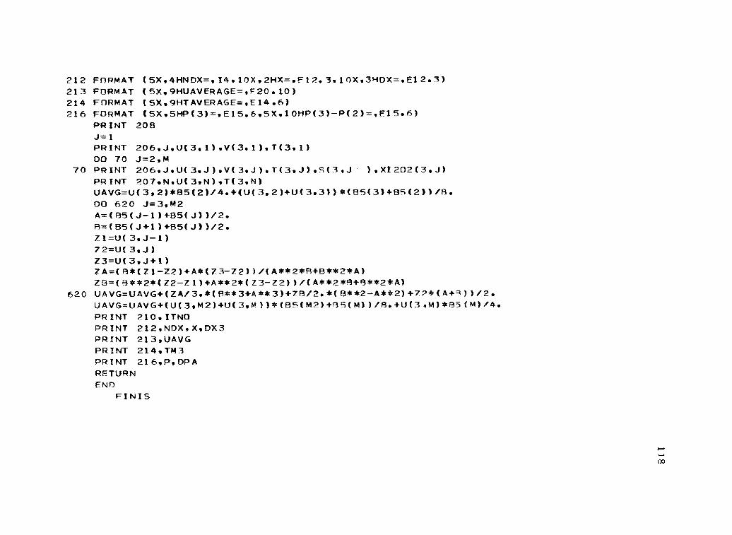
212 FORMAT (5)(.4HNDX=s14,10X,2HX=sE12.3..10X93HDX=sE12.3)213 FORMAT (8X,9HUAVERAGE=sE20.10)214 FORMAT (5)(g9HTAVERAGE=,E14.6)216 FORMAT (5)(1p5HP(3)=11E15.61,5)(1110HP(3)P(2)=,E15.6)
PRINT 2083=1PRINT 206,JsU(391),V(3.1),T(3 1)DO 70 J=204
70 PRINT 206,3,0(313),V(393),T(303),S(3,3 )0(I2O2(3,3)PRINT 207.N.U(3sN),T(39N)UAVG=U(3,2)*85(2)/4s4.(U(3,2)+U(3s3))*(85(3)+85(2))/8.DO 620 3=3,M2A=(85(J-1)+88(3))/2.E=(85(3+1)+85(3))/2.71=U(3,3-1)Z2=U(3,3)73=U(3,34-1)ZA=(811,(Z1Z2)+A*(73-72))/(A#*2*R+811c*2*A)78=03*#2*(Z2Z1)+A**2*(Z3Z2))/(A**2#8#8*#24eA)
620 UAVG=UAVG4-(ZA/3.*(8**3+A**3)+78/2.4E(B**2A**2)+72*(A+9))/2.UAVG=UAVG-4-(U(3,M2)+U(39M))*(85(M2)+8E(M))/8.+U(3,M)#85(M)/4.PRINT 210,ITNOPRINT 212INDX$X-,DX3PRINT 21311UAVGPRINT 2141,TM3PRINT 216,P,OPARETURNEND
FINIS
119
APPENDIX VI
TABULATED RESULTS

N= 1.0000 DH/RT= 0 PI PE FLEWPRA NDTL NO.= 1000 BRINKMAN ND.= 0WALL TEMP= 1.2500
NU( LOCAL) NU( MEAN)
2.500E-06 7.066E 01 2.725E 0? -1.601E-048.124E-06 4.396E 01 8.723E 01 -3.400E-041.578E-05 5.164E 01 8.528E 01 -5.849E-042.674E-05 3.069E 01 5.851F 01 -3.357E-044.235E-05 3.115E 01 5 .,??F 01 -1.435E-036.457E--05 2.431E 01 4.141E 01 -7..145E-039.620E-05 2.343E 01 3.595E 01 -3.153F-071.412E-04 1.965F 01 3.1238 01 -4.593F-02.051E-04 1.806E 01 2.783E 01 -5.644E-032.958F-04 1.551E 01 2.414E 01 -3.547E-034.243E-04 1.393E 01 2.144E 01 -1.35--026.059E-04 1.210E 01 1.880E 01 -1.947F-028.615E-04 1.078E 01 1.6658 01 -9.765F-021.219E-03 9.508E 00 1.470F 01 -3.311F-021.717E-03 8.518E 00 1.305E 01 -5.504F-022.403E-03 7.599E 00 1.1618 01 -7.693E-023.336E-03 6.845E 00 1.039E 01 -1.0638-014.583E-03 6.187E 00 9.320E 00 -1.467E-016.214E-03 5.656E 00 8.425E 00 -1.9S3F-018.293E-03 5.205E 00 7.658F OD -2.655E-011.086E-02 4.839E 00 7.039F 00 -3.477E-011.393E-02 4.547E 00 5.517E 00 -4.458E-011.747E-02 4.331E 00 5.093F 00 -5.59nF-012.141E-02 4.163E 00 5.751E 00 -6 .f352E-012 .56 8E- 02 4.025E 00 5.4748 00 --B .219 F-013.020E-02 3.9188 00 5.7478 00 -3.654E-013.488E-02 3.849E 00 5.062F 00 003.968E-02 3.801F 00 4.912F OD -1.2708 004.496E-02 3.755E 00 4.787F 00 - 1.4258 00

121
CO
C C
CC
CC
0000000000U
.LI LL
Li LIIt
LiC
IC
..C
.,C
.)C
)C
.,4et o +
.0N
I CV
+4.
+0 N
InIN
-O
N 0
N rn
r0
C\
CN
IC
\IC
1.1(I
cr;
II
IIIII
III
onconconooC
0 0 0 0 0 0 0 0 0W
LLIU
.IL IL
Ui U
.ILI
ILrri
sOa
0 Ol
CC
IN-
c00,
to aIN
.r.
lttv)
CV
CV
CV
aala a
,ctA
t
0 0 0 0 0 0 0 0 0C
0 0 C 0 0 0 0 0
LL U. Li IL U
J UJ
IJJU
.111
ILO
040°
.4N
r)N
0 0,c0 O
N C
O+
0 h-t.-I
II
air
P")
rore)
re)In
re)r) re)
In
N N
NIN
NN
NN
NN
O 0 0 0 0 0 0 0 0 0
11111 IW
UJ U
J UI
lit11J 111W
U.S
L,L1
ON
4:tgo O
N C
O C
OP
.-IN
-rn
rnre)
crC
Aocta
a, 41.ath
NO
rG
O C
O 0

N= 1.0000 DH/RT= 10 PI PE FLOWPRANDTL NO .= 1 BRINKMAN NO.= 0
WALL T EMP= 1.2500
X NU( LOCAL) NU( MEAN)
2 500E-06 6.781E 01 2 725E 0? 4.147F-048 124E-06 4.678E 01 8.329E 01 1.647F-031 578E-05 5.803E 01 8.876E 01 2s884F-032.674E-05 3.418E 01 6.112E 01 3.805E-034.235E-05 3.387E 01 5.594F 01 4.805F-036.457E-05 2.593E 01 4.379E 01 5.293E-n79 620E- 05 2 571E 01 3.967E 01 8.0457F-031.412E -04 2.102F 01 3.344E 01 1.003E-022.051E-04 1.886E 01 2.985E 01 1.222F-072.958E -04 1.573E 01 2.554E 01 1.494E-024.243E-04 1.438E 01 2.256E 01 1.877F-0?6.059E-04 1 271E 01 1 971E 01 7,193F-098 615E-04 1 139E 01 1.754E 01 7.5135F-0?1 219E-03 9 950E- 00 1 544E 01 30)13E-021.717E-03 8.984E 00 1.372F 01 3.463F-0?2.403E-03 8.096E 00 1.222E 01 3.867E-073.336E-03 7.323E 00 1.097E 01 4.153E-074.583E-03 6.607E 00 9.861E 01 4.281F-0,6 214E-03 6.062E 00 8.934E 01 4.169F-0?8.293E-03 5.623E 00 8.149E 01 3.722E-021.086E-02 5.265E 00 7.511E 00 9.96.9F-021.393E-02 4.957E 00 6.975E 01 1.548E-021.747E-02 4 733E 00 6 542E OD -9.112F-032 141E-02 4.572F 00 6.189E 0) -2.351E-0?2.568E-02 4.446E 00 5.911F OD - 4.805E -023020E-02 4.319E 00 5.679E 0) - 7.535E -023:488E-02 4.222E 00 5.489E 01 -1.045F-013.968E-02 4.170E 00 5.329E 01 -1.344P-014.456E-02 4.140F 00 5.202E 0) -1.548E-01

4.949E-02 4.083E 00 5.093E 03 -1.961E-015.444F-02 4.035E 00 4.993F 00 -2.276E-015.941E -02 4.031E 00 4.915E 01 -2..586E-016 439E-02 4.040E 00 4.843E OD - 2.892E -016.938E-02 3.998E 00 4.788E 00 -3.2n3F-017.438E-02 3.955E 00 4.733E. OD -3.514-E-017.937E-02 3.971E 00 4.683E DI -3.814P-018.437E-02 3.999E 00 4.643E 01 -4.110E-018.937E-02 3 952E 00 4.606E 01 - 4.411E -019.437E-02 3.903E 00 4.569F 01 -4.712P-01

XN=I.00FLUX=1.DXS=5.E-08DR=.02
DH/RT=0.BRINKMAN NO. =0.
DXL=5.F-03NORDIV=10 ND
IPE FLOWPRANDTL NO.=1000.
A = -11 5.
RWAL=2
X NU(LOCAL) T(WALL) T(MEAN)
2.500E-08 4.193F 02 1.003E 00 1.000E 00 -1.600E-068.219E-08 4.073E 02 1.003F 00 1.003E 00 -3.430E-061.630E-07 2.219E 02 1.005F 00 1.000E 00 -6.016E-062.835E-07 1.970E 02 1.005E 00 1.000E 00 -9.877E-064.619E-07 1.717F 02 1.006E 00 1.000E 00 -1.558F-057.261E-07 1.527E 02 1.007E 00 1.001E 00 -2.404E-051.118E-06 1.237E 02 1.008F 00 1.000E 00 -3.657F-091.698E-06 1.081F 02 1.010E 00 1.000F 00 -5.513E-052.557F-06 9.619E 01 1.011E 00 1.000E 00 -8.263E-053.830E-06 8.461E 01 1.012E 00 1.001E 00 -1.234F-045.716E-06 7.190E 01 1.014E 00 1.003E 00 -1.837E-048.510E-06 6.272E 01 1.016E 00 1.000E On -2.731E-041.265E-05 5.563E 01 1.018E 00 1.000F 00 -4.055E-041.878E-05 4.879E 01 1.021E 00 1.000F 00 -6.017E-042.785E-05 4.208E 01 1.024F 00 1.000E 00 -9.921E-044.129E -05 3.672F 01 1.028E 00 1.000E 00 -1.322F-036.118E -05 3.242E 01 1.031E 00 1.101F 00 -1.959F-039.060E-05 2.845E 01 1.036E 00 1.001F 00 -2.901E-031.341F-04 2.474E 01 1.041F 00 1.001E 00 -4.292F-031.983E-04 2.165E 01 1.047E 00 1.001E 00 -6.347E-072.930E-04 1.907E 01 1.054E 00 1.001E 00 -9.376F-034.322E-04 1.673E 01 1.062E 00 1.002F 00 -1.383E-026.363E-04 1.459E 01 1.071F 00 1.003F 00 -2.036F-029.340E-04 1.278E 01 1.082E 00 1.004F 00 -2.989F-021.365E-03 1.129E 01 1.094E 00 1.005F 00 -4.368E-021.983E-03 9.997F 00 1.108F 00 1.003F* 00 -6.345F-022.856F-03 8.870E 00 1.124F 00 1.112E no -9.139F-074.066E-03 7.929E 00 1.143E 00 1.0177 00 -1.301F-01

5.699E-03 7.171E 00 1.163E 00 1.023F 00 -14824F-017.835E-03 6.552E 00 1.184E 00 1.032E 00 -2.5078-011.052E-02 6.041F 00 1.208E 00 1.042F 00 -3.367E-011.376E-02 5.635E 00 1.233E 00 1.0538 00 -4.403E-011.750E-02 5.330E 00 1.258E 00 1.070 00 -5.600E-012.165E-02 5.103E 00 1.283E 00 1.087E 00 -6.92gE-012.611E-02 4.924E 00 1.3088 00 1.105E 00 -8.355E-013.078E-02 4.784E 00 1.333E 00 1.124F 00 -9.851E-013.558E-02 4.683E 00 1.356E 00 1.143E 00 -1.439F 004.047E-02 4.614E 00 1.379E 00 1.167E 00 -1.2958 04.540E-02 4.557E 00 1.402E 00 1.182E 00 -1.453F 005.037E-02 4.507E 00 1.424E 00 1.2028 00 -1.612E 005.535E-02 4.472E 00 1.4468 00 1.2228 00 -1.771F 006.033E-02 4.453E 00 1.467E 00 1.242E 00 -1.931F 006.533E-02 4.436E 00 1.487E 00 1.2628 00 -2.090E 007.032E-02 4.4168 00 1.509E 00 1.2828 00 -2.2518 007.532E-02 4.4018 00 1.529F 00 1.302% 00 -2.410E 008.032E-02 4.398E 00 1.549F 00 1.322% 00 -2.570E 008.532E-02 4.3958 00 1.5708 00 1.342E 00 -2.730% 009.032E-02 4.385E 00 1.590E 00 1i3628 00 -2.890% 009.532E-02 4.376E 00 1.611E 00 1.382% 00 -3.050% 00

XN=1.00FLUX=1.DXS=5.E-08DR=.02
DH/RT=5. PIPE FLOWBRINKMAN NO.=0. PRANDTL N .=1000.
DXL=5.E-03 4=-115.NDRDIV=10 NDRWAL=2
X NU(LOCAL) T(WALL) T(MFAN)
2.500E-08 4.193E 02 1.003E 00 1.000E 00 -1.591E-068.219E-08 4.095E 02 1.003E 00 1.00/E 00 -3.399E-061.630E-07 2.231E 02 1.005F 00 1.000E 00 -5.955E-062.835E-07 1.983E 02 1.005E 00 1.000F 00 -9.758E-064.619E-07 1.728E 02 1.006E 00 1.000E 00 -1.5395-057.261E-07 1.539E 02 1.007E 00 1.001E 00 -1.374E-051.118E-06 1.247E 02 1.008F 00 1.000E 00 -3.611E-051.698E-06 1.092E 02 1.009E 00 1.001E 00 -5.441F-052.557E-06 9.733E 01 1.011E 00 1.001E 00 7'1.152E-053.830E-06 8.567E 01 1.012E 00 1.000F 00 -1.217F-045.716E-06 7.287E 01 1.014F 00 1.003E 00 -1.812F-048.510E-06 6.377E 01 1.016E 00 1.001E 00 -2.691F-041.265E-05 5.672E 01 1.018E 00 1.001E 00 -3.993E-041.878E-05 4.981E 01 1.020E 00 1.000E 00 -5.919F-042.785E-05 4.304E 01 1.024F 00 1.000E 00 -8.767E-044.129E-05 3.772E 01 1.027E 00 1.000E 00 - 1.297E -036.118E-05 3.343E 01 1.030E 00 1.101E 00 -1.918F-039.060E-05 2.941E 01 1.035E 00 1.001F 00 -2.833E-031.341E-04 2.565E 01 1.040F 00 1.001E 00 -4.178F-0171.983F-04 2.254F 01 1.045F 00 1.001E 00 -6.148E-072.930E-04 1.995E 01 1.052E 00 1.001F 00 -9.027F-014.322E-04 1.758E 01 1.059E 00 I.002F 00 1.320E -026.363E-04 1.541E 01 1.068E 00 1.003F 00 -1.921E-029.340E-04 1.358E 01 1.078E 00 1.004E 00 - 2.779E -021.365E -03 1.206E 01 1.089F 00 1.005F on -3.95sE-021.983E-03 1.072E 01 1.101E 00 1.003E 00 -5.663F-022.856E-03 9.556E 00 1.116E 00 I.112F 00 -7.933F-024.066E-03 8.581E 00 1.133F 00 1.0177 00 - 1.092E -01

5.699E-03 7.791E 00 1.151F 00 1.023F 00 -1.473F-017.835F-03 7.137E 00 1.172E 00 1.032F 00 -1.939F-011.052E-02 6.589E 00 1.194F 00 1.042E 00 -2.4311E-011.376E-02 6.154E 00 1.218E 00 1.055E 00 -3.095F-011.750E-02 5.832E 00 1.242E 00 1.070E 00 -3.727E-012.165E-02 5.583E 00 1.266E 00 1.087E 00 -4.382E-012.611E-02 5.383F 00 1.290E 00 1.105E 00 -5.030E-013.078E-02 5.230E 00 1.315E 00 1.123E 00 -5.658F-013.558E"-02 5.119E 00 1.338E 00 1.143E 00 -6.255E-014.047E-02 5.039E 00 1.361E 00 1.162E 00 -6.822E-014.540E-02 4.970E 00 1.383E 00 1.182F 00 -7.356E-015.037E-02 4.909E 00 1.406E 00 1.202E 00 -7.860E-015.535E-02 4.869E 00 1.427E 00 1.222F 00 -8.334F-016.033E-02 4.842E 00 1.448F 00 1.242E 00 -8.782F-016.533E-02 4.813F 00 1.470E 00 1.262E 00 -9.206E-017.032E-02 4.783F 00 1 4 91.F 00 I.287E 00 -9.607E-017.532E--02 4.762E 00 1.512F 00 1.302F 00 -9.987F-018.032E-02 4.754E 00 1.532E 00 10322E 00 -1.135E 0084,532E-02 4.740E 00 1.553E 00 1.342E 00 -I.069F 009.032E-02 4.718E 00 1.574E 00 1.362E 00 -1.102E 009411532E02 4.706E 00 1.595E 00 1.382E 00 -1.133E 00

XN=I.00FLUX=1.DXS=5.E-08OR=.02
DH/RT=10.BRINKMAN NO. =O.
DXL=5.E-03NORDIV=10
IPE FLOWPRANDTL NO.=1000.
A=-115.RWAL=2
X NU(LOCAL) T(WALL) T(MEAN)
2.500E-08 4.193E 02 1.003E 00 1.000E 00 -1.582E-068.219E-08 4.118E 02 1.003F 00 1.000E 00 -3.368E-061.630E-07 2.243E 02 1.005E 00 1.001E 00 -5.894F-062.835E-07 1.996E 02 1.005E 00 1.003E 00 - 9.645F -064.619E-07 1.739E 02 1.006E 00 1.000E 00 -1521E-057.261E-07 1.550E 02 1.007E 00 1.000F 00 -2.346E-051.118E-06 1.256E 02 1.008E 00 1.000F On -3.566F-051.698E-06 1.103E 02 1.009E 00 1.000E 00 -5.371E-052.557E-06 9.845E 01 1.010E 00 1.000E 00 -8.043E-053.830E-06 8.671E 01 1.012E 00 1.000E 00 -1.200E-045.716E-06 7.383E 01 1.014E 00 1.000F 00 -1.786E-048.510E-06 6.481E 01 1.016E 00 1.000E 00 -2.652E-04I.265F-05 5.778E 01 1.018F 00 1.000E on - 3.932F -041.878F-05 5.080E 01 1.020E 00 1.000E 00 -5.825E-042.785E-05 4.398E 01 1.023F 00 1.001F 00 -8.619F-044.129E-05 3.869E 01 1.026E 00 1.000F 00 -1.274F-036.118E -05 3.441E 01 1.030E 00 1.001E 00 -1.890E-039.060E-05 3.032E 01 1.034E 00 1.001E 00 -2.771F-031.341E-04 2.651E 01 1.039F 00 1.001E 00 -4.071E-031.983E-04 2.341E 01 1 .044E 00 1.001F 00 -5.963E-032.930E-04 2.080F 01 1.049F 00 1.001E 00 -8.699F-074.322E-04 1.837E 01 1.056E 00 1.002E 00 -1.262E-026.363E-04 1.616E 01 1.065E 00 1.003E 00 -1.819E-029.340E-04 1.431F 01 1.074F 00
11:00(0145; rOlft;
-2.595F-021.365F-03 1.276E 01 1.084E 00 -3.653E-021.983E-03 1.137E 01 1.096F 00 1.109E no -5.096E-022.856E-03 1.016E 01 1.110E 00 1.011E 00 -6.961E-024.066E-03 9.158E 00 1.125E 00 1.015E 00 -9.296E-02

5.699E-03 8.3335 00 1.143E 00 1.023F 00 -1.212E-017.835E-03 7.6395 00 1.162F 00 1.0315 00 -1.534E-011.052E-02 7.061E 00 1.1845 00 1.0425 00 -1.882E-011.376E-02 6.608E 00 1.2065 00 1.055E 00 -2.242E-011.750E-02 6.269E 00 1.2305 00 1.070F 00 -2.595E-012.1655-02 5.9965 00 1.254E 00 1.087E 00 -2.9255-012.611E-02 5.774E 00 1.2785 00 1.103E 00 -3.227E-013.078E-02 5.623E 00 1.301E 00 1.123F 00 -3.498E-013.5585-02 5.506E 00 1.325E 00 1.143E 00 -3.737E-014.047E-02 5.4055 00 1.3485 00 1.162F 00 -3.947E-014.540E-02 5.318E 00 1.370E 00 1.1825 00 -4.1315-015.0375-..02 5.266E 00 1.3925 00 1.202E 00 -4.296E-015.535E-02 5.232E 00 1.413E 00 1.2225 00 -4.441E-016.033E-02 5.173E 00 1.4365 00 1.2435 00 -4.5695-016.533E-02 5.1265 00 1.4575 00 1.262F 00 -4.684E-017.032E-02 5.111E 00 1.478F 00 1.2825 00 -4.787E-017.532E-02 5.1075 00 1.498E 00 1.302E 00 -4.883E-018.032E-02 5.063E 00 1.5205 00 1.322F 00 -4.963E-018.532E-02 5.012E 00 1.541E 00 1.342F 00 -5.0385-a-019.032E-02 5.019E 00 1.5615 00 1.3515 00 -5.107E-019.532E-02 5.0345 00 1.5815 00 1.3835 00 -5.170E-01

XN=1.00FLUX=2.DXS=5.E-08DR=.02
DH/RT=5. RIPE FLOWBRINKMAN NO.=0. PRANOTL NO.=1000.
DXL=5.E-03 A=-115.NDRDIV=10 NDRWAL=2
X NU(LOCAL) T(WALL) T(MEAN)
2.500E-08 3.970E 02 1.005F 00 1.00E 00 -1.583E-068.219E-08 3.903E 02 1.005E 00 1.000F 00 -3.368E-061.630E-07 2.178E 02 1.009E 00 1.000E 00 -5.894E-162.835E-07 1.944E 02 1.011E 00 1.000F 00 -9.649E-064.619E-07 1.699E 02 1.012E 00 1.000E 00 -1,520E-057.261E-07 1.519E 02 1.013F 00 1.000E 00 -2.346E-091.118E-06 1.236E 02 1.016E 00 1.000E DO -3.567F-091.698E-06 1.087F 02 1.019E 00 1.000F 00 -5.371F-052.557E-06 9.715F 01 1.021E 00 1.000E 00 -1.045E-053.830E-06 8.569E 01 1.024E 00 1.00DE 00 -1.201F-045.716E-06 7.308E'01 1.028E 00 1.000E 00 -1.786F-048.510E-06 6.422E 01 1.031E 00 1.000F 00 -2.652E-041.265E-05 5.730E 01 1.035F 00 1.000E 00 -3.933F-041.878E-05 5.043E 01 1.040E 00 1,000F 00 -9.827E-042.785E-05 4.369E 01 1.046F 00 1.001E 00 -1.623E-044.129E-05 3.845E 01 1.053E 00 1.001E 00 -1.274E-036.118E-05 3.420E 01 1.059E 00 1.001E 00 -1.881E-039.060E-05 3.015E 01 1.067F 00 1.001E 00 -2.772F-031.341E-04 2.637E 01 1.077E 00 1.001F 00 -4.075F-071.983E-04 2.328F 01 1.088F 00 1.002E 00 -5.971F-032.930E-04 2.069E 01 1.099E 00 1.003E 00 -8.714E-074.322E-04 1.827E 01 1.113F 00 1.004E 00 -1.265E-026.363E-04 1.607E 01 1.130E 00 1.005E 00 - 1.825E -029.340E-04 1.422E 01 1.148E 00 1.003E 00 -2.601E-021.365E-03 1.267E 01 1.169E 00 1.011E On -3.617E-021.983E-03 1.128E 01 1.193F 00 1.015E 00 -9.144E-022.856E-03 1.007E 01 1.222E 00 1.023E 00 -7.051E-024.066E-03 9.051E 00 1.254E 00 1.033E 00 -9.466E-02

5.699E-03 8.215E 00 1.289F 00 1.046E 00 -1.242E-017.835E-03 7.515E 00 1.329F 00 1.063F 00 -1.585F-011.052E-02 6.920E 00 14373E 00 1.084E 00 -1.964E-011.376E-02 6.451E 00 1.420E 00 1.113E 00 -2.367E-011.750E-02 6.102E 00 1.468E 00 1.140E 00 -2.775F-012.165E-02 5.817E 00 1.517E 00 1.173E 00 -3.169E7012.611E-02 5.593E 00 1.567E 00 1.209F 00 -3.544F-013.078E-02 5.425E 00 1.615E 00 1.246E 00 -3.893E-013.558E-02 5.294E 00 1.663E 00 1.285E 00 -4.215F-014.047E-02 5.200E 00 1.709F 00 1.324F 00 -4.510E-014.540E-02 5.110E 00 1.755E 00 1.363E 00 -4.781E-015.037E-02 5.043E 00 1.800E 00 1.404F 00 -9.031F-015.535E-..02 4.993E 00 1.843E 00 1.443F 00 -5.262E-016.033E-02 4.948E 00 1.888E 00 1.484E 00 -5.475E-016.533E-02 4.913F 00 1.931E 00 1.523E 00 -5.674F-017.032E-02 4.871E 00 1.973E 00 1.563E 00 -5.860E-017.532E-02 4.848E 00 2.016E 00 1.603F 00 -6.034F-018.032E-02 4.827E 00 2.058F 00 1.643E 00 -6.197F-018.532E-02 4.799E 00 2.100F 00 1.684E 00 -6.351F-019.032E-02 4.780E 00 2.142E 00 1.723E 00 -6.497E-019.532E-02 4.760E 00 2.183E 00 1.763E 00 -6.634E-01
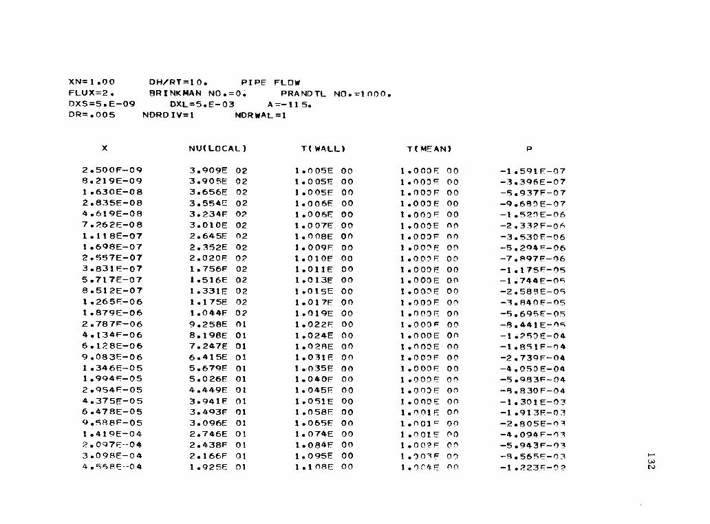
XN=1.00FLUX=2.DXS=5.E-09DR=.005
DH/RT=10.BRINKMAN N0.=0.
DXL=5.E-03NORDIV=1 ND
IPF FLOWPRANDTL NO.=1000.
A=-115.RWAL=1
X NU(LOCAL) T(WALL) T(MEAN)
2.500E*09 3.909E 02 1.005E 00 1.000E 00 -1.591E-078.219E-09 3.905E 02 1.005E 00 1.003E 00 -3.396E-071.630E-08 3.656E 02 1.005E 00 1.000E 00 -5.937F-072.835E-08 3.554E 02 1.006E 00 1.000E 00 --9.681F-074.619E-08 3.234E 02 1.006E 00 1.000F 00 -1.-520E-067.262E-08 3.010E 02 1.007E 00 1.001E 00 -2.332F-061.118E-07 2.645E 02 1.008E 00 1.00E nn -3.530E-061.698E-07 2.352E 02 1.009E 00 1.000E 00 -5.294E-062.557E-07 2.020F 02 1.010E 00 1.001E 00 -7.897E-063.831E-07 1.756E 02 1.011E 00 1.000E 00 -1.175F-055.717E-07 1.516E 02 1.013E 00 1.000E 00 -1.744E-058.512E-07 1.331E 02 1.015E 00 1.000E 00 -2.589E-051.265E-06 1.175E 02 1.017E 00 1.003E 00 -3.840E-051.879E-06 1.044E 02 1.019E 00 1.000E 00 -5.695E-052.787E-06 9.258E 01 1.022E 00 i.000F 00 -1.441E-054.134E-06 8.198F 01 1.024E 00 1.000E 00 -1.250E-046.128E-06 7.247E 01 1.028E 00 1.000E 00 -1.851F-049.083E-06 6.415E 01 1.031E 00 1.000E 00 -2.739F-041.346E-05 5.679E 01 1.035E 00 1.000E 00 -4.050E-041.994E-05 5.026E 01 1.040E 00 1.000E 00 -5.983E042.954E-05 4.449E 01 1.045E 00 1.001E 00 -1.830E-044.375E-05 3.941E 01 1.051E 00 1.000E 00 -1.301E-'036.478E-05 3.493E 01 1.058E 00 1.001F 00 -1.913F-039.588E-05 3.096E 01 1.065E 00 1.001E 00 -2.805E-011.419E-04 2.746E 01 1.074E 00 1.001E 00 -4.094E-032.097E-04 2.438E 01 1.084E 00 1.007E Cr' -5.943E033.098E-04 2.166F 01 1.095E 00 1.003F OD -8.565E-034.568E-04 1.925E 01 1.108E 00 1.004F 00 -1.223E-n2

6.723F-04 1.713E 01 1.122F 00 1.005F 00 -1.728E-02 9.862E-04 1.528E 01 1.139E 00 1.003F 00 -2.405E-02 1.440E-03 1.364E 01 1.158E 00 1.012E 00 -3.293F-02 2.090E-03 1.221E 01 1.181F 00 1.017E 00 -4.417F-02 3.006E-03 1.096E 01 1.207E 00 1.024F 00 -5,775E-02 4.270E-03 9.881E 00 1.237E 00 1.034E 00 - 7.344E -02 5.971E-03 8.963E 00 1.271F 00 1.048E 00 -9.073F-02 8.183E-03 8.196E 00 1.309E 00 1.065E 00 -1.084E-01 1.095E-02 7.556E 00 1.352F 00 1.087E 00 -1.256F-01 1.426E-02 7.058E 00 1.397E 00 1.114F 00 -1.417E-01 1.807E-02 6.654E 00 1.444E 00 1.143E 00 -1.557E-01 2.227E-02 6.334E 00 1.493E 00 1.173E 00 -1.676E-01 2.677E-02 6.107E 00 1.540E 00 1.213F 00 -1.776E-01 3.146E-02 5.912E 00 1.588E 00 1.250F 00 -1.859F-01 3.628E-02 5.762E 00 1.637E 00 1.290E 00 -1.927F-01 4.117E-02 5.634E 00 1.684E 00 1.329E 00 -1.983E-01 4.611E-02 5.559E 00 1.728E 00 1.369E 00 -2.031F-01 5.107E-02 5.484E 00 1.770F 00 1.405F 00 -2.071E-01 5.606E-02 5.397E 00 1.819E 00 1.448E 00 -2.105E-01 6.104E-02 5.330E 00 1.863E 00 1.483E 00 -2.133E-01 6.604E-02 5.296E 00 1.906E 00 1.529E 00 -2.158F-01 7.103E-02 5.288E 00 1.942E 00 1.563E 00 -2.181E-01 7.603E-02 5.213E 00 1.990E 00 1.605E 00 -2.201F-01 8.103E-02 5.154E 00 2.037E 00 1.649E 00 - 2.217F -01 8.603E-02 5.128E 00 2.079E 00 1.689E 00 -2.232E-01 9.103E-02 5.160E 00 2.111E 00 1.723E 00 -2.246E-01 9.603E-02 5.11SE 00 2.155E 00 1.764E 00 -2.258E-01
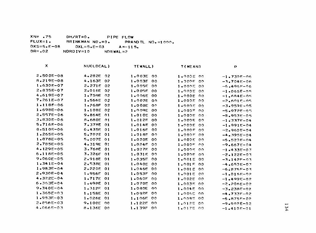
XN= .75FLUX=1.DXS=5.E-08DR=.02
DH/RT=0.BRINKMAN NO.=0.
DXL=5.E-03NORDIV=10 ND
IPE FLOWPRANDTL NO.=1000.
A=-115.RWAL=2
X NU(LOCAL) T(WALL) T(MEAN)
2.500E-08 4.282F 02 1.003E 00 1.000E 00 -1.730E-068.219E-08 4.163E 02 1.003E 00 1.000F 00 - 3.70E -0F1.630E-07 2.271E 02 1.005E 00 1.000E 00 -6.496F-062.835E-07 2.016E 02 1.005E 00 1.001E 00 -1.066E-054.619E-07 1.759E 02 1.006E 00 1.000E 00 -1.684F-057.261E-07 1.566E 02 1.007E 00 1.000E 00 -2.601F-051.118E-06 1.268E 02 1.008E 00 1.000E 00 -3.951E-051.698E-06 1.108E 02 1.009E 00 1.001E 00 -5.972E-052.557E-06 9.864E 01 1.010E 00 1.000F 00 - 8.953E -053.830E-06 8.680E 01 1.012F 00 1.000E 00 -1.337F-045.716E-06 7.378E 01 1.014E 00 1.000E 00 -1.991E-048.510E-06 6.435E 01 1.016F 00 1.000E 00 -7.960E-041.265E-05 5.707E 01 1.018E 00 1.000F 00 - 4.395E -041.878E-05 5.007E 01 1.020E 00 1.000E 00 -6.520E-042.785E-05 4.319E 01 1.024E 00 1.000F 00 -9.667F-044.129E-05 3.768E 01 1.027E 00 1.000F 00 -1433E-036.118E-05 3.326E 01 1.031E 00 1.001E 00- -2.122F-079.060E-05 2.918E 01 1.035E 00 1.001E 00 -3.142F-031.341E-04 2.538E 01 1.040E 00 1.001F 00 -4.650E-031.983E-04 2.220E 01 1.046E 00 1.001E 00 -6.876F-032.930E-04 1.956E 01 1.053F 00 1.001E 00 -1.016F-024.322E-04 1.717E 01 1.060F 00 1.002E 00 -1.499F-026.363E-04 1.498E 01 1.070E 00 1.003E 00 - 2.206E -029.340E-04 1.312F 01 1.080E 00 1.004E 00 - 3.238F -021.365E-03 1.158E 01 1.092E 00 1.006E 00 -4.733E-021.983E-03 1.026E 01 1.106E 00 1.008E 00 -6.875F-022.856E-03 9.100E 00 1.122E 00 1.012F 00 -9.902F-024.066E-03 8.136E 00 1.139E 00 1.017E 00 -1.410E-01

5.699E-03 7.357E 00 1.159E 00 1.023F 00 -1.976F-017.835E-03 6.722E 00 1.180E 00 1.032E 00 - 2.715E -011.052F-02 6.200E 00 1.204E 00 1.042E 00 -3.648E-011.376E-02 5.786E 00 1.228E 00 1.055E 00 -4.771E-01I.750E-02 5.475E 00 1.253F 00 1.070E 00 -6.068F-012.165E-02 5.243E 00 I.278E 00 1.087E 00 - 7.507E -012.611E-02 5.062E 00 1.302E 00 1.105E 00 -9.054E-013.078E-02 4.920E 00 1.327E 00 1.124E 00 -1.067F 003.558E-02 4.817E 00 1.350E 00 1.143F 00 - 1.234E 004.047E-02 4.748E 00 1.373E 00 1.162E 00 -1.403F 004.540E-02 4.692E 00 1.395E 00 1.182E 00 -1.574E 005.037E-02 4.642F 00 1.418E 00 1.202F 00 -I.746E 005.535E-02 4.606E 00 1.439E 00 1.222E 00 - 1.919E 006.033E-02 4.587F 00 1.460F 00 1.242E 00 -2.092E 006.533E-02 4.573E 00 1.481E 00 1.262F 00 -2.265E 007.032E-02 4.552E 00 1.502F 00 1.282E 00 -2.438E 007.532E-02 4.534F 00 1.522E 00 1.302F 00 -2.611E 008.032E-02 4.532E 00 1.543E 00 1.322E 00 -2.785E 008.532E-02 4.535E 00 I.563E 00 1.342E 00 -2.958E 009.032E-02 4.524E 00 1.583F 00 1.362F 00 -3.132E 009.532E-02 4.509E 00 1.604E 00 1.382F 00 -3.305E 00

XN= .75FLUX=1.DXS=5.E-08OR=.02
OH/RT=5. PIPE FLOWBRINKMAN NO.=0. PRANDTL NO.=1000.
DXL=5.E-03 A=-115.NORDIV=10 NORWAL=2
X NU(LOCAL) T(WALL) T(MEAN)
2.500E-08 4.282E 02 1.003F 00 1.000F 00 -1.721E-058.219F-08 4.181F 02 1.003E 00 1.000E 00 -3.675E-061.630E-07 2.282E 02 1.005E 00 1.000F 00 -6.437E-062.835E-07 2.030E 02 1.005E 00 1.000E OD -1.055F-054.619E-07 1.769E 02 1.006E 00 1.000E 00 -1.665E-097.261E-07 1.577E 02 1.007E 00 1.000F 00 -2.F74F-051.118E-06 1.278E 02 1.008E 00 1.000F 00 -3.919E-091.698E-06 1.120F 02 1.009F 00 1.00DE 00 -5.908F-052.557E-06 9.976E 01 1.010E 00 1.000F 00 -8.854F-053.830E-06 8.786E 01 1.012E 00 1.000F 00 -1.322F-045.716E-06 7.474E 01 1.014E 00 1.000E 00 -1.968F-048.510E-06 6.537E 01 1.016E 00 1.000E 00 -2.925E-041.265E-05 5.814E 01 1.018E 00 1.000E 00 -4.340E-041.878E-05 5.110E 01 1.020E 00 1.000E 00 -6.435E-042.785E-05 4.415E 01 1.023F 00 1.003E 00 -9.534E-044.129E-05 3.864E 01 1.026E 00 1.000E 00 -1.441E-076.118E-05 3.425E 01 1.0305 00 1.0015 00 -2.088F-039.060E-05 3.015E 01 1.034E 00 1.0015 00 -3.089E-031.341E-04 2.628E 01 1.0395 00 1.001E 00 -4.554F-031.983E-04 2.308E 01 1.044E 00 1.0015 00 -6.710E-032.930E-04 2.043E 01 1.050E 00 1.0015 OC -9.863E-074.322E-04 1.801E 01 1.057E 00 1.002E 00 -1.445E-026.3635-04 1.578E 01 1.066E 00 1.003F 00 -2.110E-029.340E-04 1.389E 01 1.0765 00 1.004E 00 -3.063F-021.3655-03 1.233E 01 1.087E 00 1.0059 00 -4.415F-021.983E-03 1.097E 01 1.099F 00 1.009= nn -6.3035-022.8565-03 9.7695 00 1.114E 00 1.012E 00 -8.888E-024.066E-03 8.764E 00 1.1315 00 1.117F 0() -1.2345-01

0 0 03 00 -4 0)S I ILI, 0 (J1 0 01
AJJ (.41 coJ (+J
A) r vin in in in ii in in
O 000000N N N
(7) J N N10001 0 01 0 U1 0 in (A 0 00 Or
Li1 LAI 4> cn 1. 0)
in in in mmmmm in in in in ino 0oo0000o 00000N N N NNNN ry
(flUl (11 U1 01 01 01 U1 CA O
00 aD 0) CO CO 0 0 0 0 0 . N *-4 4) N N0- c4 CI Cr. -4 0 41 01 Iv CO U1 r.1 P. 0 0 01 CO CA OD 01CA OD 01 P-P Co N 01 N 01 0 03 C)1 0. J). 0 q!)rnmmmrnrnlrninrnrnrn;flmrnrnmmrniTlrnll0 0 0 0 0 0 0 0 0 0 0 0 0 0 0 0 0 0 0 0 00 3 0 0 0 0 0 0 0 0 0 0 0 0 0 0 0 0 0 0 0
.....10 1001 0. 0. I. 0.0 001 0.0 1.000
01 LTI 1:11 PPai U' .0. IN 00 0 OD LID -4in 71 in in in in in in in rn in in in in m mm 11 111 r11
0 0 0 0 0 0 0 0 0 0 0 0 0 0 0 0 0 0 0 0 00 0 0 0 0 0 0 0 0 0 0 0 0 0 0 0 0 0 0 0 0
1.0 000 1.0 1.10 0.0 000 0.0 0 0.0 101 . - 4 1 r S ) V IV 00 3 3 0 0
L11 4. L4 INv IV IV IN Al IV N A) U1 01 -4 JI 1\)
in in in m in in in in m in in in in rfl in in in iiO 3 0 0 3 0 0 0 0O 0 3 0 0 0 0 :0 0 O 0 0 0 3 0 0 0 0 0 0 00 0 0 0 0 (3 0 0 0 0 0 (3
I II I I II I II0- 0. 0. 1.0 0. 000 .00
U1 P N 0 04> 1) OD 14 0' 0 4 0
Co CA 1) 1:).1 uN
11 71 71 in in in in in in in
O 0 0 0 0 0 0 0 0 0O 3 0 3 3 3 3 0 3 .3
I I I I 1 I I I I I I
.1) .14 LA (.7, 01 PP (41 V V 04a a
Ul CO 1/40 P.° A.) 41:1' 17% OD IV in4), .3) o 4), CO .P 44 0 :,,J11 )) 4. V 4) (.11 ON v .0
rn m rnm'nrnriiinmI I I I I I I I I I IO 3330030000
- 1.0 00 .0 0. 0. 0-

XN= .75FLUX=1.DXS=5.E-08DR=.02
DH/RT=10.BRINKMAN NO.=0
DXL=5.E-03NORDIV=10
PIPE FLOWPRANDTL N33.=1000.
A=-115.DRWAL=2
X NU(LOCAL) T(WALL) T(MEAN)
2.500E-08 4.282E 02 1.003E 00 1.000F 00 -1.712F-068.219E-08 4.200E 02 1.003F 00 1.000E 00 -3.648F-061.630E-07 2.294E 02 1.005F 00 1.000E 00 -6.379F-062.835E-07 2.044E 02 1.005E 00 1.000F 00 -1.045F-054.619E-07 1.780F 02 1.006E 00 1.000F 00 -1.649F-057.261E -07 1.587F 02 1.007E 00 1.00OF 00 -2.549E-051.118E-06 1.288F 02 1.008F 00 1.100E no -3.87SP-01.698E-06 1.131E 02 1.009F 00 1.00nF nn -5.844E-052.557E-06 1.009F 02 1.010F 00 1.000E 00 -8.756F-053.830E-06 8.891E 01 1.012F 00 1.000E 00 -1.307F-045.716E-06 7.570E 01 1.013F 00 1.000F 00 -1.946E-048.510E-06 6.638F 01 1.015F 00 1.001E 00 -2.890E-041.265E-05 5.919E 01 1.017F 00 1.000F 00 -4.287F-041.878E-05 5.211F 01 1.020E 00 1.000F 00 -6.354F-042.785E-05 4.509E 01 1.023F 00 1.000F 00 -9.406F-044.129F-05 3.959E 01 1.026F 00 1.000F 00 -1.391F-036.118E-05 3.523E 01 1.029F 00 1.001F 00 -2.055F-039.060E-05 3.109F 01 1.033E 00 1.001F 00 -3.032F-031.341E-04 2.716E 01 1.039E 00 1.001E 00 -4.464F-071.983E-04 2.392E 01 1.043E 00 1.001E 00 -6.554F-072.930E-04 2.127F 01 1.048E 00 1.001F 00 -9.589F-034.322E-04 1.882E 01 1:055E 00 1.002F 00 -1.397E-026.363E -04 1.654E 01 1.063E 00 1.003E 00 -2.023F-029.340E-04 1.461F 01 1.072F 00 1.004F on -2.907F-021.365E -03 1.304F 01 1.082E 00 1.0017 00 -4.136E-021.983F-03 1.164F 01 1.094F 00 1.0097 00 -5.812F-022.856F-03 1.038F 01 1.108F 00 1.012F 00 -8.031E-024.066F-03 9.337E 00 1.124F 00 1.0177 no -1.090E-01

139
. .4I.
.4 0.0.1
9.4,1
Irar.
orm
C C
C C
CC
CC
CO
O C
. CC
C C
CC
C C
CI
II
11
II
11 111
11 111
111
U.)
L..
U.'L
UU
U. L
LL
U.
U.
14U
J4r.t
Nri
CIC
0a. a N
tOr. C
LI m
UC
1
ttkr
re.,rr,
,44ttr.
fr r,ft IP
C C
O ,ct
cr,rn cc
eI
Irr, r:U
)U)U
)U)'cC
NN
NN
Nct '
11 11 11 111
111
111 11 11
11
C000000 C
000C0C
0OC
CC
0000000.00000C
C 0C
CC
000C0
IL!
LU
LI
IliU
..'U
)al
U.:
U.
U.!
U.J
uiL
I Li
Li
LU
U.
LI
L'
C tr.,
in.ct.
tric.1
r, rirn
c, co41.
u*)ct)
Nkr,
CC
, C N
C C
Ctt
C, C
CC
C 0
0-4C
,1N
.".:
11.111.4
V.4
11.1o4.4
p4444.4
r444.444
- pry.4 .1 04
000000000000000000000000000000000000000000IL
U.
Li IL
U.!
UJ
IL L
.U
.JU
.:U
J11.1
UJ U
JC
-N
- C. tr
NC
r, N C
V...I
rrco in 4 a
in00
CV
ct1/40
cctt)
r-,14
rf)0.1
(\!C'.1
(\.]r
rr)
tr.4rt. 4 4 4 tr.
totr,
frap44
oml
.1.4
.4..41w
.4 ..... 1.16.41......
000000000000000000000000000000000000000000
1.1..U
.,L
IL
,U
.,.L
I LI L
i LI L
UU
JLU
UJ U
J WU
J LU
U.J
0 a cy,to 0 co a. N
C rc) 4 N
O C
0 re)C
, U) N
In N.
rn,4
u)N
N N
NPP
4.44. 0S
CO
r.14.
11)1.0
1.0tf)
lf)in
Lo
NN
NN
INN
NN
NN
NIN
NN
NN
NIN
N0 0 0 0 C
0 0 0 0 0 0 0 0 0 0 0 0 C 0 0 0
1111
11 11 11 11111 111I
I1
U.1
LU
UJ W
W 11.1
U.,
U.1
toUIC
LI W
W L
L..
CT
'IC
) N /,) 0 IP
CO
CC
0 1".tr)
re/re) N
N N
N N
frL
r)I`
rt.ri
re)ri
uacc o rc)
- s.0 0 10 0 It:U
l 0 1.1) C 1f) C
1.0L
I,e
aS
.IP
rd.4 O
s! NA
t11)
lc)+
4;k0
cc cc a a

XN= .50FLUX=1.DXS=5.E-08DR=.02
DHIRT=0. PIPE FLOWBRINKMAN NO.=0. PRANDTL NO.=1000.
DXL=5.F -03 A = -115.
NORDIV=10 NDRWAL=2
X NU(LOCAL) TI WALL) T(MEAN)
2.500E-08 4.462F 02 1.002E 00 1.001F 00 -1.985F-068.219E-08 4.346E 02 1.003F 00 1.000E 00 -4.249F-061.630E-07 2.372E 02 1.004F 00 1.000E 00 -7.445E-062.835F-07 2.106F 02 1.005E 00 1.000E 00 -1.221F-054.619E-07 1.839E 02 1.006F 00 1.000F 00 -1.92PF-057.261F-07 1.639E 02 1.006F 00 1.000E 00 -2.984E-051.118E-06 1.330E 02 1.008E 00 1.000E 00 -4.950E-051.598E -06 1.162E 02 1.009F 00 1.000E 00 -6.876E-052.557E -06 1.033E 02 1.010E 00 1.000E 00 -1.032F-043.830E-06 9.092F 01 1.011F 00 1.000F 00 -1.542E-045.716E-06 7.740E 01 1.013E 00 1.0007 00 -2.296F-048.510E-06 6.748E 01 1.015F 00 1.000E 00 -3.415E-041.265E-05 5.980F 01 1.017E 00 1.000E 00 -5.070E-041.878F-05 5.243E 01 1.019F 00 1.000F 00 -7.522E-042.785E-05 4.527E 01 1.022F 00 1.000E 00 -1.115F-034.129F-05 3.949E 01 1.026E 00 1.000F 00 -1.652E-036.118E-05 3.484F 01 1.029E 00 1.000F 00 -2.448F-079.060E -05 3.056E 01 1.033E 00 1.0017 00 -3.624E-031.341F-04 2.658F 01 1 .038F 00 1.001F 00 -5.362E-071.983E-04 2.324F 01 1.044E 00 1.001E 00 -7.910E-072.930E-04 2.048E 01 1.050E 00 1.001F 00 -1.172F-024.322E-04 1.798E 01 1.098E 00 00 -1.728F-026.363E-04 1.569E 01 1.067F 00 1:73'1; -2.544E-029.340E-04 1.374E 01 1.077F 00 1.004E 00 -3.735E-021.365E-031.983E-03
1.213E1.073E
01
01
1.088E1.101F
0000 1-1.:Z; fr)N)-,
-5.459F-02-7.927F-02
2.856F-03 9.520E 00 1.117F 00 1.1120- 00 -1.142F-014.0,56F-73 8.513E 00 1.134F 00 1.1'-7 () -1.626E-01

141
4.44 *4-4 .4 C C c 0 C 0 C C ccO 0 occ., 0 0 C 0 C O C 0 0 C. C 0 C C.1111 IIU. LU U.) Il Lt U. Li U.: U. U. It tL U_ U. LL LLJ U.4 LC U.4
CO Cs. 4:I' rn CC' LP it fr) N N CV
P4.4 1r C C Ln et P) NI M MN 4-4 N 1.0 C? 0) C N 0. CC N 0 CC 0 N /14 0. CC
rr, tt if) C CC CV CV C\ .1 CV. CV r. r CC. r
O C C. 0 C: C C C C G 0 C C C^ C G CC C C C C C C C C C C C C C C C 0 0 01LL U.. Li: LI' U. 1.11 Lt: U. L1 U. Lit U: 11.1 U-1 U. U.ir ci in rfi Nl N NI N. CV N N n. N N N NN In 4 in N. c N 0 co c N er 0 co c N 4 rC cc,O C c c C G M 44 -4 -4 -4 C\ CV C.1 CV CV 141 re. r 14^ r^
on on on on on on on 00,41 on on on on. on On on on on n4 on on oof
C00)C000000040000000000O 0000000000000:0000000LI LI U._ 1.1.1 LL U. LLI LL ILl U.. LU U LU LI L W 11.1 U-Pr) At 0 O 1.11 C1' r r 0 Pe, r N.- CO 0" O nr.4 0.8 0.1 N Ntf N. 0, N rt kr. 0, 41. 0 CO 0 N NI LT N CT
N N N rn rn M r .ch d st .4 4 If 1.1) LP LP IP10 Ison On on on on on on en on ........ M on on on
O 000000000000000000000 0 0 000 G G 000 0 0 00000000ILI LI- LL UJ W U.: 1.1J UJ Li IL LI LI L; 1.1_1 W LU I.0 L..1
CC It. 0 0 4.1 0' G rn 0 G G ck, 0 N 0 VJ Pr) In \Oa PI (P 0 P1 Oh. ...it C) 00, re') CO 4t In on N IP1/40 0 .4 0 N. t M c) a 0, co (r. cc cc N. N N Nti t, 0 0 Lo Lc) in to Ln at e 4 4 4' it 4 At It it At
Nir)NNNNNNNNNNNNNNNNNNINO 0 0 0 0 0 0 0 0 0 0 0 0 0 0 0 0 C 0 0 0111111111111111111111UJ W U- LL1 UJ W UJ W LU LL1 W U.1 LI! U.1 111 LJJ LU LLI EL. 1.1.1
CT tfi N 0 0 0 .4-4 CO CC N- 0 N tfl rf) m (N.1 N N N N NN1 N- U^ 4t tt M N1 tr. tfl M r M M tf) MCC C Fri N. t0 C Ir 0 Ln C LO O U1 C U^ o lI C LO
tO N ."4 N N 4t In Li) i7 h N l7C cr a a.
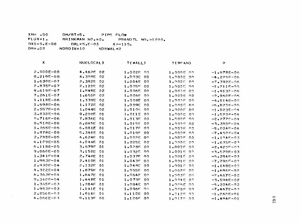
XN= .50FLUX=1.DXS=5.E-08DR=.02
DH/RT=5.BRINKMAN NO.=0.
DXL=5.F-03NORDIV=10 ND
IPE FLOWPRANDTL NO.=1000.
4=-115.RWAL=2
X NU(LOCAL) T(WALL) T(MFAN)
2.500E-08 4.462E 02 1.002E 00 1.000E no -1.978E-068.219E-08 4.359E 02 1.003E 00 1.000F on -4.225F-061.630E-07 2.382E 02 1.004F 00
"-7.392F-06
2.835E-07 2.120E 02 1.005E 00 = 00 -1.211E-054.619E-07 1.849E 02 1.006E 00 1.003F 00 -1.913E-057.261E-07 1.650E 02 1.006E 00 1.000E 00 -2.960E-051.118E-06 1.339E 02 1.008E 00 1.00IF 00 -4.514E-051.698E-06 1.172E 02 1.009E 00 1.000E 00 -6.820E-052.557E-06 1.044E 02 1.010F 00 1.000E 00 -1.027E-043.830E-06 9.200F 01 1.011E 00 1.000E 00 -1.529E-045.716E-06 7.836E 01 1.013F 00 -2.277F-048.510E-06 6.845E 01 1.015F 00 :::).);; ;) - 3.355F -041.265F-05 6.081E 01 1.017F 00 1.000E 00 -5.024E-041.878E-05 5.346E 01 1.019F 00 1.000F 00 -7.452F-042.785E-05 4.624E 01 1.022E 00 1.000F 00 -1.104E-074.129E-05 4.044F 01 1.025E 00 1.000F 00 -1.635E-036.118E-05 3.579E 01 1.028E 00 1.000F 00 -2.420E-039.060E-05 3.150E 01 1.032E 00 1.001 E 00 -3.579E-031.341F-04 2.748E 01 1 .037F 00 1.001F 00 -5.214E-071.983E-04 2.410F 01 1.043F 00 I.001F 00 -7.796E-072.930E-04 2.132E 01 1.048E 00 1.001F 00 -1.148E-024.322F-04 1.879F 01 1.055E 00 1.002E 00 -1.686E-026.363F-04 1.647E 01 1.064E 00 1.107F 00 -2.467E-029.340E-04 1.448F 01 1.073E 00 1.004F 00 -3.594E-021.365F-03 1.284F 01 1.084E 00 1.006F 00 -5.204F-021.983E -03 1.141E 01 1.096F 00 1.009E 00 -7.467E-022.856E-03 1.016E 01 1.110E 00 1.012E 00 -1.060E-014.066E-03 9.113E 00 1.126F 00 1 .017F 00 -1.4194E-01

5.699E-03 8.262E 00 1.144E 00 1.023E 00 -2.038F-017.835E-03 7.562E 00 1.164E 00 1.032F 00 -2.739E-011.052F-02 6.986E 00 1.185E 00 1.042F 00 -3.589F-011.376E-02 6.523F 00 1.208E 00 1.055E 00 -4.571F-011.750E-02 6.174E 00 I.232E 00 1.070F 00 -5.658E-012.165E-02 5.917F 00 1.256E 00 1.087E on -6.e19F-ol2.61IF-02 5.710E 00 1.280E 00 1.105F 00 -8.012E-013.078E-02 5.543F 00 1.304E 00 1.123E 00 -9.209E-013.558E-02 5.434E 00 1.327F 00 1.143F 00 -1.040E On4.047F-02 5.356E 00 1.349E 00 1.162E 00 - 1.157F 004.540E-02 5.280F 00 1.371F 00 1.182E 00 -1.271E 005.037E-02 5.220E 00 1.394E 00 1.202F 00 -1.182E 005.535E-02 5.184E 00 1.415F 00 1.222E 00 -1.490F 006.033E-02 5.156F 00 1.436F 00 1.242E 00 -1.595E On6.533F-02 5.125E 00 1.457E 00 1.262F no -1.697F no7.032E-02 5.103F 00 1.478F 00 1.282F 00 -1.797E 007.532E-02 5.084E 00 1.499F 00 1.302E 00 -1.894F 008.032F-02 5.068E 00 1.519E On 1.322E 00 -1.988F 008.532E-02 5.057E 00 1.540F 00 1.342F 00 -2.080E 009.032E-02 5.047E 00 1.560E 00 1.362F no -2.170E On9.532E-02 5.032F 00 1.581F 00 1.382E 00 -2.258E 00

XN= .50FLUX=1.DXS=5.E-08DR=.02
DH/RT=10.BRINKMAN NO.=0.
DXL=5.E-03NDRDIV=10 ND
IPE FLOWPRANDTL NO.=1000.
4=-115.RwAL=2
X NU(LOCAL) T(WALL) T(MEAN)
2.500E-08 4.454E 02 1.002F 00 1.000E 00 -1.971E-168.219E-08 4.362E 02 1.003E 00 1.001E 00 -4.201E-061.630E-07 2.391E 02 1.004E 00 1.000E 00 -7.337F-062.835E-07 2.135E 02 1.005F 00 1.000E 00 -1.201E-054.619E-07 1.860E 02 1.006E 00 1.000F 00 -1.896F-057.261E-07 1.659E 02 1.006F 00 1.000E 00 -2.935E-051.118E-06 1.347F 02 1.008F 00 1.000F 00 -4.477F-051.698F-06 1.183E 02 1.009E 00 1.00OF 00 -6.763F-052.557E-06 1.055E 02 1.010E 00 1.000F 00 -1.014E-043.830E-06 9.305E 01 1.011F 00 1.000E 00 -1.516E-045.716E-06 7.929E 01 1.013F 00 1.000F 00 -2.257F-048.510E-06 6.939E 01 1.015F on 1.000E 00 -3.355F-041.265F-05 6.181F 01 1.016E 00 1.000F 00 -4.979F-041.878E-05 5.447E 01 1.019F 00 1.000F 00 -7.383E-042.785E-05 4.718E 01 1.022E 00 1.000F 00 -1.094F-n74.129E-05 4.135E 01 1.025F 00 1.000F 00 -1.619F-036.118E-05 3.671F 01 1.028E 00 1.000F 00 -2.393E-039.060E-05 3.241F 01 1.031F 00 1.001F 00 -7.535E-031.341E-04 2.834E 01 1.036F 00 1.001E 00 -5.241E-031.983F-04 2.493E 01 1.041E 00 1.001E 00 -7.669F-032.930E-04 2.211E 01 1.047E 00 1.001F 00 -1.126E-024.322F-04 1.956E 01 1.053E 00 1.002F 00 -1.646F-026.363E-04 1.719E 01 1.061E 00 1.007E 00 -2.396F-029.340E-04 1.517E 01 1.070E 00 1.004E 00 -3.467F-021.365E-03 1.349E 01 1.080E 00 1.005E 00 -4.975F-021.983E-03 1.203E 01 1.091F 00 1.103F 00 -7.059E-022.856E-03 1.073E 01 1.105F 00 1.012F 00 -9.897E-024.066E-07 9.641F 00 1.120F 00 1.017 00 -1.363F-01

145
t..4 .4 C
.C
. C C
C C
C., C
C.:.
C.00 C
CC
C C
C C
C C
C C
C...C
C:C
C:0C
U.
ILILL
LtjLL U
JLL
LLLiJ
LLLL
LLtij
LLLL
to 0 Li)41.
CC
rn0:
(Y.
N tfl
U t tO
0 -t Crn .4 a, 44
4:t.to 0 rei
co a Att
rn 0 4 0'4.
CC
, NC
C 4 C
CC
t0 44
7e.
frtr
CC
011111111111111111111
C00000C
CC
CC
CC
OC
CC
000CO
C000C
0C0C
CC
OC
C00C
0C0
U:
U.
U.
11.1IL
LUU
iILI
Ui
LLIU
.ILI
L.'LLJ
U.I
U:
LL1LL
Lt.U
.1LU
c\tfe) 4 tf)
N.,
CO
0 N 4 +
13C
C 0 N
J.ett
1/40a" 0 N
te,C
0 C.
C C
(N.
CN
0,10,1
frrn.
_-4 .44.4
+.4
9.1 -4-4 oo.1
CO
0C0000000O
C 0 C
OC
CC
OO
O 00000000000000000000
OW
UJ
LLU
.1LIJ
U-
Lt./IL
ILILL
LI./LL
LL1
rnrel
0 cc 0ct.)
4. ICa .0
N(\I
CJ N
I NI N
Iv) m r
frl4:t
4tIP
If)411
aa
r. .4 v.fo.
.4.4 v.
.4- ).4
O 0 00 0 0 00000 0 0 0
00 0 0 0C
0 00 0 0 0 0
0 000000CC
CC
W W
W W
W IL"
UJ U
J WU
J UJ
LULLJ
ILIW
LtJ U.!
LLIILI
U.
Lt.!C
Oo L
s.)C
O N
if) 0 CC
NcC
In 0 NJ 0 4
r)C
+1
r')LO
N If)
40,C
)C
O o tO
rn 0 cc C 0 0I
CO
CO
N 4.)
t0 +0 +
0 IPtf)
Lr)lf)
LPtf)
tf)tr in to tr)
re)re)
N N
N N
NN
NN
NN
NN
NN
NO
0 0 0 0 0 0 0 0 0 0 0 0 0 0 0 0 0 0 0 0111111111111111111111
LIJ LL WU
JUJ LU
LULL
LIJLU
UiW
11111 U
i141 LLJW
1.1.1U
I11) C
1 0 0 11)04 C
O C
C N
, 0 tsre)
NN
N N
0're)
LP N
. LP +
0 .4LC
Iet et
relrf)
rr)rn
rn+
4 co o re)r-
oo it)
IP 0 tf) 0 LP
0 IP 0 LP
tf) NN
lt 4.If.!
tC)
0,N
N. C
O C
O 0 0'

XN= .25 PIPE FLOWFULLY-DEV. VELOCITY AND UNIFORM FLUX=1.0DXS=5.F-09 OXL=5.E-03 A=-115.DR=.005 NORDIV=1 NDRwAL=1
X NU(LOCAL) T(WALL) T(MEAN)
2.500E-09 3.951E 02 1.003E 00 1.000F 00 -2.800E-078.219E-09 3.947E 02 1.003F 00 1.101E on -6.002F-071.630E-08 3.795E 02 1.003E 00 1.000E 00 -1.053F-062.835E-08 3.724F 02 1.003F 00 1.000E 01 -1.728E-064.619E-08 3.503E 02 1.003E 00 1.000E 00 -2.726F-097.262E-08 3.329E 02 1.003F 00 1.001E 00 -4.206F-061.118E-07 3.027E 02 1.003E 00 1.000E 00 -6.399E-091.698E-07 2.752E 02 1.004E 00 1.000F 00 -9.648F-092.557E-07 2.408E 02 1.004E 00 1,003E 00 -1.446E-053.831E-07 2.102E 02 1.005E 00 1.000F 00 -2.159E-055.717E-07 1.802E 02 1.006F 00 1.000F 00 -3.216F-058.512E-07 1.557E 02 1.006E 00 1.000F 00 -4.781E-051.265E-06 1.351F 02 1.007E 00 1.000E 00 -7.099E-051.879E-06 1.188F 02 1.008E-00 1.001F 00 -1.053F-042.787F-06 1.050E 02 1.010E 00 1.001E 00 -1.562F-044.134E-06 9.295E 01 1.011F 00 1.000F 00 -2.316E-046.128F-06 8.184E 01 1.012F 00 1.000F 00 -3.413F-049.083E-06 7.191E 01 1.014E 00 1.000F 00 -5.088F-041..346E-05 6.318E 01 1.016E 00 1.001F 00 -7.538E-041.994F-05 5.554E 01 1.018E 00 1.00IF 00 -1.117E-032.954E-05 4.874E 01 1.021E 00 1.000F 00 -1.654E-034.375E-05 4.271F 01 1.024E 00 1.000F 00 -2.45IF-016.478E-05 3.742E 01 1.027E 00 1.000F 00 -3.628E-039.588E-05 3.280F 01 1.031F 00 1.001E Or -5.369E-031.419F-04 2.873E 01 1.035E 00 1.001F 00 -7.944F-032.097E-04 2.515E 01 1.041F 00 1.001F 00 -1.174F-023.098E-04 2.203E 01 1.047E 00 1.001E on -14735E-024.568E-04 1.932F 01 1.054F 00 1.0027 00 -2.558F-02

6.7238 -04 1.696E 01 1.062E 00 1.003F 00 -3.765F-029.862E-04 1.492E 01 1.071F 00 1.004F 00 -5.5235-021.440E -03 1.3165 01 1.0825 00 1.005E 00 -8.055E-022.090E-03 1.1655 01 1.094F 00 14.009F 00 -1.1705-013.006E-03 1.038F 01 1.108E 00 1.012F 00 -1.683E-014.270E-03 9.3035 00 1.1255 00 1.017E 00 -2.3915-015.971E-03 8.416F 00 1.1435 00 1.0245 00 -3.3445-018.183E -03 7.6975 00 1.163E 00 1.033E 00 -4.582F-011.0955 -02 7.1235 00 1.184F 00 1.044F 00 -6.1325-011.426E-02 6.674E 00 1.2075 00 1.0575 00 -7.988E-011.807E-02 6.3295 00 1.230E 00 1.0725 00 -1.0175 002.227E-02 6.0705 00 1.254F 00 1.089F 00 -1.2475 002.677E-02 5.8775 00 1.2775 00 1.1075 00 -1.499F 003.146E-02 5.734E 00 1.3005 00 1.125E 00 -1.7625 003.628E-02 5.627F 00 1.3235 00 1.147E 00 -2.031F 004.117E-02 5.548E 00 1.3455 00 1.165E 00 -2.1055 004.611E-02 5.490E 00 1.366E 00 1.184E 00 -2.582E 005.107E-02 5.447E 00 1.388E 00 1.2045 00 -2.860F 005.606E-02 5.4145 00 1.409E 00 1.224F 00 -301395 006.104E-02 5.3905 00 1.429E 00 1.244F 00 -3.418E 006.604E-02 5.372E 00 1.4505 00 1.764F 00 -3.698E 007.103E-02 5.359F 00 1.4705 00 1.284F 00 -3.978F 007.603E-02 5.348E 00 1.491E 00 1.304E 00 -4.258E 008.103E-02 5.340E 00 1.5115 00 1.324E 00 -4.538F 008.603E-02 5.335E 00 1.5315 00 1.3445 00 -4.818E 009.103E-02 5.3315 00 1.5515 00 1.3645 00 -5.098F 009.603E-02 5.3285 00 1.571E 00 1.384F 00 -5.3785 00

N= 1.0000 OH/RT= 0 PIPE FLOWPRANDTL NO.= 1000 BRINKMAN NO.=FLUX= 1.4142 SIN(100*PI*X)DXS=5.E-08 DXL=5.E-04 A=-4600.DR=.02 NORDIV=10 NORWAL=2
0
X FLUX T(WALL) T(MEAN)
2.500E-08 1.111E-05 1.000F 00 1.100E 00 -1.600E-051..037E-07 4.609E-05 1.000E 00 1.000F 00 -4.120E-063.018E-07 1.341E-04 1.000E 00 1.003E 00 -1.046F-058.178E-07 3.633E-04 1.000E 00 1.000E 00 -7.697E-052.153E-06 9.566E -04 1.000E 00 1.000E 01 -6.970E-055.605E-06 2.490E-03 1.000E 00 1.103E 00 -1.802E-041.448F -05 6.434E-03 1.000E 00 1.001E 00 -4.642F-043.700E-05 1.644E-02 1.000F 00 00 -1.185E-039.229E-05 4.100E-0 2 1.001E 00 1= 00 -2.954F-032.179E -04 9.675E-02 1.003F 00 1.000F 00 -6.975E-074.627F-04 2.049F-01 1.009F 00 1.000E 00 -1.481E-028.412E-04 3.694E-01 1.021E 00 1.001F 00 -2.692E-021.306E-03 5.642E-01 1.038E 00 1.002E 00 -4.181E-021.800E-03 7.579E-01 1.058E 00 1.003E 00 -5.761E-022.300E-03 9.351F-01 1.079E 00 1.005E 00 - 7.359F -022.800E-03 1.090E 00 1.100E 00 1.007E 00 -8.959F-023.300E-03 1.217E 00 1.121E 00 1.009E 00 -1.056E-013.800E-03 1.315E 00 1.140F 00 1.012F 00 -1.215E-014.300E-03 1.380E 00 1.158F 00 1.014E 00 -1.376E-014.800E-03 1.411F 00 1.173F 00 1.017( 00 -1.536E-015.300E-03 1.408E 00 1.185E 00 1.020E 00 -1.696F-015.800E-03 1.370E 00 1.194F 00 1.023F 00 -1.856E-016.300E-03 1.298F 00 1.199E 00 1.025E 00 -2.016E-015.800E-03 1.194E 00 1.701F 00 1.029E 00 -2.175F-017.300E-03 1.061F 00 1.198E 00 1.030E 00 -2.335E-017.800E -03 9.015E-01 1.192E 00 1.032E 00 -2.495F-018+300E-03 7.200E-01 1.192E 00 1 .011E 00 -2.656F-01

8.800E-03 5.207E-01 1.169E 00 1.035E 00 -2.815F-019.300E-03 3.086F-01 1.153E 00 1.035E 00 -5.975E-019.800E-03 8.893E-02 1.134E 00 1.035F 00 -3.135F-011.030E-02 0 1.119E 00 1.035E 00 -3.296F-011.080E-02 0 1.109E 00 1.035F 00 -3.456E-011.130E -02 0 1.102E 00 1.035F 00 3.615F-011.180E-02 0 1.097E 00 1.035E 00 -3.775E-01

N= 1.0000 DH/RT= 10 PIPE FLOWPRANDTL NO.= 1000 BRINKMAN NO.=FLUX= 1.4142 SIN(100*PI*X)DXS=5.E-08 DXL=5.E-04 A=-4600.DR=.02 NDRDIV =10 NORWAL=7
X
0
FLUX T(WALL) T(MEAN)
2.500E-08 1.111F-05 1.000F 00 1.000F 00 -1.600E-061.037E-07 4.609E-05 1.000F 00 1.001F 00 -4.120E-063.018E-07 1.341E-04 1.000E 00 1.000F 00 -1.046F-058.178E -07 3.633E-04 1.000E 00 1.000F 00 -2.697F-052.153E-06 9.566E-04 1.000F 00 1.000E 00 -6.970E-055.605E-06 2.490E -03 1.000E 00 1.000E 00 7-1.802E-041.448F-05 6.434F -03 1.000E 00 1.000E 00 -4.642F-043.700E-05 1.644E-02 1.000F 00 1.000E 00 -1.185E-039.229E -05 4.100E-02 1.001E 00 1.000F 00 -7.957F-032.179E-04 9.675E-02 1.003F 00 1.000F 00 -6.960E-034.627F-04 2.049E-01 1.009E 00 1.000E 00 -1.471E-028.412E-04 3.694E-01 1.021E 00 1.001F 00 -2.645F-021.306E-03 5.642E-01 1.036F 00 1.002E 00 - 4.029F -021.800E-03 7.579F-01 1.054E 00 1.003F 00 -5.410E-022.300E -03 9.351E-01 1.072F 00 1.005F 00 -6.711F-072.800E-03 1.090E 00 1.090F 00 1.007E 00 -7.925F-023.300E-03 1.217E 00 1.107E 00 1.001E on -9.049E-023.800E-03 1.315E 00 1.122F 00 1.012E 00 -1.009F-014.300E-03 1.380E 00 1.136E 00 1.014F 00 -1.105F-014.800E-03 1.411E 00 1.148E 00 1.017E 00 -1.195F-015.300E-03 1.408E 00 1.158E 00 1.020E 00 -1.279E-015.800 -03 1.370E 00 1.165F 00 1.022E 00 -1.358E-016.310E-03 1.298F 00 1.170E 00 1.025F 00 -1.433F-016.810E-03 1.194E 00 1.172F 00 1.078F 00 - 1.506E -017.300E-03 1.061F 00 1.172F 00 1.030E 00 -1.575F-017.800E-03 9.015F-01 1.168F 00 1.037F 00 -1.643F-018.300E-03 7.200E-01 1.160F 00 1.(3'F 00 -1.712E-01

8.800E-03 5.207E-01 1.150F 00 1.034F 00 -1.780E-019.300E-03 3.086E-01 1.138E 00 1.035F 00 -1.848E-019.800E-03 8.893E-02 1.121F 00 1.033E 00 - 1.919E -011.030E-02 0 1.109E 00 1.035E 00 -1.994E-011.080E-02 0 1.100E 00 1.035E 00 -2.070E-011.130E-02 0 1.094E 00 1.035E 00 -2.147E-011.180E-02 0 1.090E 00 1.035E 00 -7.228F-01
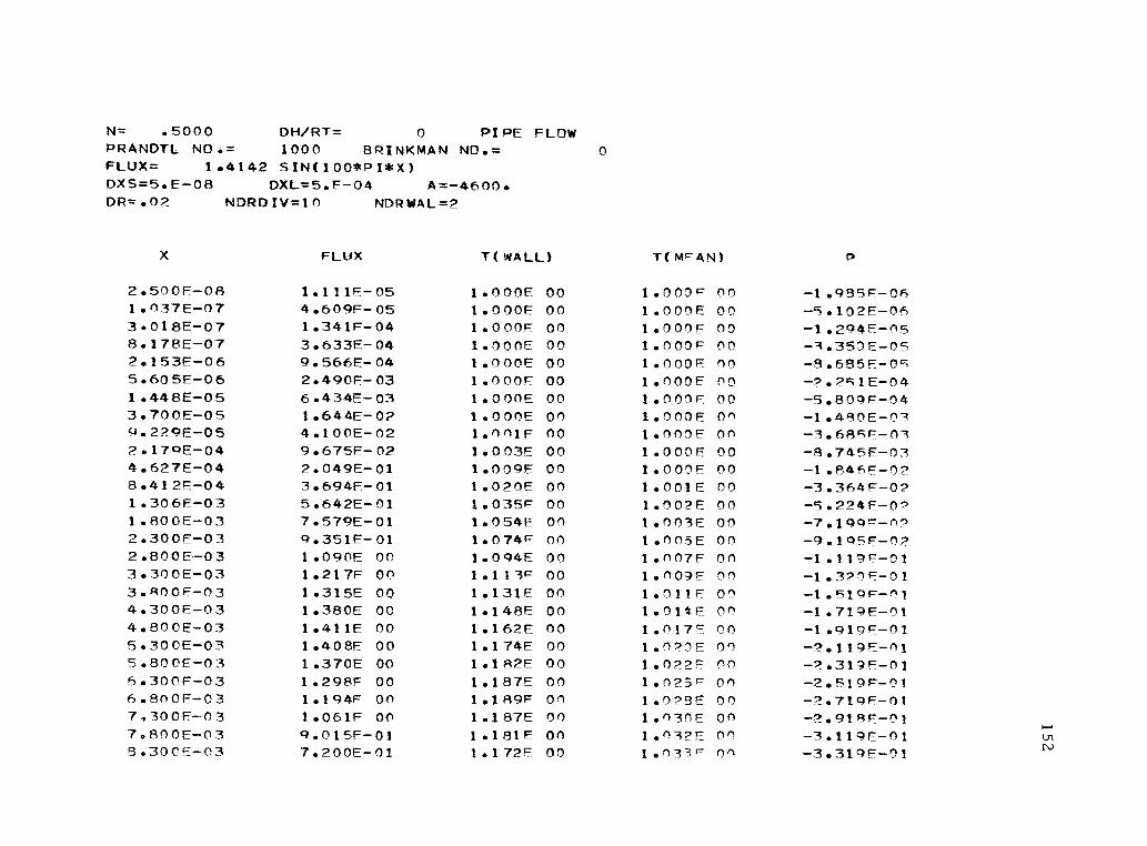
N= .5000 OH/RT= 0 PIPE FLOWPRANDTL NO.= 1000 BRINKMAN NO.=FLUX= 1.4142 SIN(100*PI*X)DXS=5.F-08 DXL=5.F-04 A=-4600.OR=.02 NDRDIV=10 NORWAL=2
X FLUX T(WALL) T(MFAN)
2.500E-08 1.111E-05 1.000F 00 1.000E 00 -1.985E-061.037E-07 4.609E-05 1.000F 00 1.000E 00 -9.102E-063.018E-07 1.341E-04 1.000F 00 1.001E 00 1.294F -058.178F-07 3.633E-04 1.000E 00 1.000E 00 -3.350E-092.153E-06 9.566E-04 1.000E 00 1.000E 00 -9.685E-055.605E-06 2.490E-03 1.000E 00 1.000E 00 -?.291E-041.448E-05 6.434E-03 1.000E 00 1.000E 00 -5.809E-043.700E-05 1.644E-02 1.000E 00 1.001E 00 -1.480E-039.229E-05 4.100E-02 1.001E 00 1.000E 00 -3.685E-032.179F-04 9.675E-02 1.003E 00 1.000E 00 -8.745E-034.627E-04 2.049E-01 1.009F 00 1.000E 00 -1.846E-028.412E-04 3.694E-01 1.020E 00 1.001E 00 -3.164E-021.306E-03 5.642E -01 1.035E 00 1.002E 00 -9.224F-021.800E-03 7.579E-01 1.054E 00 1.003E 00 -7.199F-022.300E-03 9.351E-01 1.074E 00 1.005E 00 -9.195E-022.800E-03 1.090E 00 1.094E 00 1.007E 00 -1.119E-013.300E-03 1.217E 00 1.113E 00 1.009E 00 -1.320E-013.800E -03 1.315E 00 1.131E 00 1.011E 00 -1.519E-014.300E-03 1.380E 00 1i148F 00 1.014E 00 -1.719F-014.800E-03 1.411E 00 1.162E 00 1.017E 00 -1.919F-015.300E-03 1.408E 00 1.174E 00 1.021F 00 -2.119E-019.800E-03 1.370E 00 1.182E 00 1.022E 00 -2.319E-015.300E -03 1.298E 00 1.187E 00 1.023E 00 -2.519E-016.800E-03 1.194E 00 1.189E 00 1.029E 00 -2.719F-017.300E-03 1.061E 00 1.187E 00 1.030E 00 -2.918E-01
1--,7.800E-03 9.015E-01 1.181E 00 1.03F 00 -3.119E-01 (xi
N9.300E-03 7.200E-01 1.172E 00 1.033F 0?. -3.319E-01

8.800E-03 5.207E-01 1.160E 00 1.035E 00 -3.518E-019.300E-03 3.086E-01 1.144E 00 I.035E 00 -7.718E-019.800E-03 8.893E-02 1.127E 00 1.035E 00 - 3.918E -011.030E-02 0 1.113E 00 1.036E 00 -4.118E-011.080E-02 0 1.104E 00 1.035E 00 -4.317E-011.130E-02 0 1.097F 00 1.035F 00 -4.518E-011.180E-02 0 1.093E 00 1.035E 00 7-4.718F-01

N= .5000 OH/RI= 10 PIPE FLOWPRANDTL NO.= 1000 8 INKMAN NO.=FLUX= 1.4142 SIN(100 *PI *X)DXS= 5.E -08 DXL =5.E -04 A=-4600.DR=.02 NORDIV=10 NORWAL=2
0
X FLUX T(WALL) T(MEAN)
2.500E-08 1.111E-05 1.000E 00 1.000E 00 -1.985E-061.037E-07 4.609E-05 1.000E 00 1.000E 00 -5.102E-053.018E-07 1.341E-04 1.000E 00 1.000F 00 -1.294F-058.178E-07 3.633E-04 1.000F 00 1.0005 00 -3.350E-052.153E-06 9.566E-04 1.000E 00 1.000E 00 -1.686E-055.605E-06 2.490E-03 1.000E 00 1.0015 00 -2.2515-041.448E-05 6.434E-03 1.0005 00 1.000F 00 -5.809E-043.700E-05 1.644E-02 1.0005 00 1.000E 00 -1.4805-079.2295-05 4.100E-02 1.001E 00 1.003F 01 -1.6845-032.179E-04 9.675E-02 1.0035 00 1.0005 00 -9.733E-034.627E-04 2.049E-01 1.009F 00 1.0005 00 -1.839E-028.412E-04 3.694E-01 1.0195 00 1.001F 00 -3.3295-021.3065-03 5.6425-01 1.0345 00 1.002F 00 -5.116E-021.8005-03 7.579E-01 1.0515 00 1.003E 00 -6.9565-022.300E-03 9.351E-01 1.0685 00 1.0035 00 -8.752E-022.8005-03 1.090E 00 1.085E 00 1.007E 00 -1.0485-013.300E-03 1.217E 00 1.101E 00 1.0095 00 -1.217E-013.800E-03 1.315E 00 1.117F 00 1.012F 00 -1.374E-014.3005-03 1.3805 00 1.131E 00 1.015E 00 -1.5285-014.8005-03 1.4115 00 1.141E 00 1.1175 00 -1.678E-015.300E-03 1.408F 00 1.1515 00 1.0205 00 -1.819F-015.8005-03 1.370E 00 1.1585'00 1.022F 00 -1.961E-016.300E-03 1.298E 00 1.164E 00 1.025E 00 -2.0975-016.8005-03 1.194E 00 1.1675 00 1.0285 00 -2.226E-017.300E-03 1.061F 00 1.1655 00 1.030E 00 -2.353F-017.800E-03 9.015E-01 1.1605 00 1.0325 00 -7.485E-019.300E-03 7.2005-01 1 .153E 00 1 .077F 00 ---.6?0E-01

8.800E-03 5.207E-01 1.145F 00 1.034E 00 -2.745E-019.300E-03 3.086E-01 1.134E 00 1.037F 00 -2.871F-019.800E-03 8.893E-02 1.117E 00 1.036F 00 -3.001F-011.030E-02 0 1.106F 00 1.035F 00 -3.139F-011.080E-02 0 1.097E 00 1.035E 00 -3.283E-011.130E-02 0 1.092E 00 1.035E 00 -3.421E-011.180E-02 0 1.087E 00 1.037F 00 -3.554F-01

N= 1.0000PRANOTL NO.=AT Y=0, FLUX=
DH/RT= 0 CHANNEL FLOW1000 BRINKMAN NO.=1.0000
AT Y=1, FLUX= 1.0000DXS=5.E-08 OXL=5.E-03 A=-115.DR =.02 NORDIV=10 NORWAL=2
Z NU(LUCAL) T(WALL) T(MFAN)
1.250E-08 6.872F 02 1.003E 00 1.000F 00 -6.000E-074.109E-08 6.720E 02 1.003E 00 1.000F 00 -1.286E-068.150E-08 3.832E 02 1.005E 00 1.000E 00 -2.256F-061.417E-07 3.428E 02 1.006E 00 1.000E 00 -3.702F-062.309E-07 3.005E 02 1.007E 00 1.000E 00 -5.842E-063.631E-07 2.686E 02 1.007F 00 1.000E 00 -9.014F-065.588E-07 2.190E 02 1.009E 00 1.000E 00 -1,371E-058.489E-07 1.925E 02 1.010E 00 1.000E no -2.067F-091.279E-06 1.720E 02 1.012E 00 1.001E 00 -3.099F-051.915E-06 1.518E 02 1.013F 00 1.001E 00 -4.626E-052.858E-06 1.295E 02 1.015E 00 1.00DF 00 -6.889F-094.255E -06 1.135E 02 1.018E 00 1.000E 00 -1.024F-046.324E-06 1.011E 02 1.020E 00 1.000E 00 -1.521F-049.389E-06 8.888E 01 1.023E 00 1.000E 00 -2.256E-041.393E-05 7.688E 01 1.026E 00 1.000E 00 -3.149E-042.065F-05 6.742E 01 1.030F 00 1.000F nn -4.958E-043.059E-05 5.980F 01 1.034F 00 1.100F 00 -7.344F-044.530E-05 5.264E 01 1.038E 00 1.000F 00 -1.087E-036.704E -05 4.592E 01 1.044F 00 1.000F 00 -1.609F-039.915E-05 4.035E 01 1.050F 00 1.001F 00 -2.380E-031.465F-04 3.566E 01 1.057E 00 1.001 F 00 -3.515E-032.161E -04 3.135E 01 1.065F 00 1.001F 00 -5.187E-033.182E-04 2.744F 01 1.074F 00 1.001F 00 - 7.535F -034.670E -04 2.417E 01 1.085E 00 1.0025 00 -1.121E-025.829E-04 2.146E 01 1.096E 00 1.003F 00 -1.638E-029.915E-04 1.906E 01 1.1095 00 1.0047 00 - 2.380E -02

1.428F -03 1.696E1.522E
01
011.124F1.140E
0000
1.006E 001.003E 00
- 3.42_71 -02
-4.879E-022.850E-03 1.381E 01 1.156E 00 1.011E 00 -6.839F-023.917E-03 1.262E 01 1.174F 00 1.016E 00 -9.402F-025.261E-03 1.162E 01 1S193E 00 1.021E 00 7-1.263E-016.880E-03 1.085E 01 1.212E 00 1.023E 00 -1.651E-018.751E-03 1.026F 01 1.230E 00 1.035F 00 7-2.100E011.083E-02 9.790E 00 1.248E 00 1.043E 00 -2.598E-011.306E-02 9.413E 00 1.265E 00 1.052E 00 -3.133E-011.539E-02 9.134F 00 1.281E 00 1.062F 00 -3.694E-011.779E-02 8.935E 00 1.295E 00 1.071E 00 4.270F -012.023E-02 8.776E 00 1.309E 00 1.081E 00 -4.856E-012.270E -02 8.641E 00 1.322F 00 1.091E 00 -5.448F-012.518E-02 8.544E 00 1.335F 00 1.101E 00 -6.044E-012.767E-02 8.483E 00 1.347E 00 1.111E 00 -6.641E-013.017E-02 8.429E 00 1.358E 00 1.121E 00 -7.240E-013.266E-02 8.375E 00 1.370E 00 1.131F 00 -7.819E-013.516E-02 8.339E 00 1.381E 00 1.141E 00 -8.439E-013.766E-02 8.324E 00 1.391E 00 1.151F 00 -9.039E-014.016E-02 8.307E 00 1.402E 00 1.161E 00 -9.638E-014.266E..-02 8.280E 00 1.412E 00 1.171F 00 -1.024E 004.516E -02 8.266E 00 1.423E 00 1.181E 00 -1.084E 004.766E-02 8.268E 00 1.433E 00 1.191F 00 -1.144E 005.016E-02 8.263E 00 1.443E 00 1.201F 00 -1.204E 005.266E-02 8.246E 00 1.453E 00 1.211E 00 1.264E 005.516E-02 8.240E 00 1.463E 00 1.221F 00 -1.324E 005.766E-02 8.247E 00 1.473E 00 1.231F 00 -1.384E 006.016E-02 8.247E 00 1.483E 00 1.241F 00 -1.444E 006.266E-02 8.234E 00 1.494E 00 1.251F 00 -1.514F 006.516F-02 8.230F 00 1.504E 00 1.261F 00 -1.564E 006.766E-02 8.239E 00 1.514E 00 1.271F 00 -1.624E 007.016F-02 8.241E 00 1.523E 00 1.281E 00 -1.684F 007.266F-02 8.229E 00 1.534F 00 1.291E 00 -1.744E 00
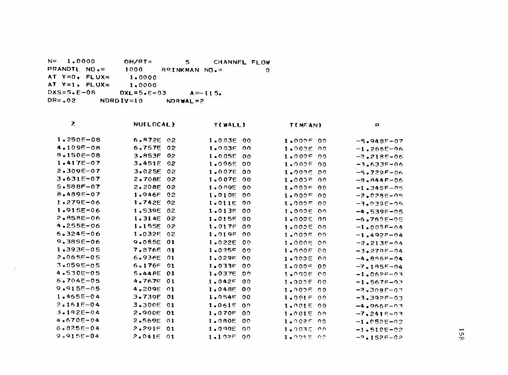
N= 1.0000 OH/PT= 5 CHANNEL FLOWPRANDTL NO.= 1000 BRINKMAN NO.= 0AT Y=0, FLUX= 1.0000AT Y=1, FLUX= 1.0000DXS=5.E-08 OXL=5.E-03 4=-115.DR=.02 NORDIV=10 NDRWAL =2
NU(LOCAL) T(WALL) T(MFAN)
1.2505-08 6.8725 02 1.003E 00 1.000F 00 -5.948F-074.1095-08 6.7575 02 1.003F 00 1.0015 00 -1.266E-068.150E-08 3.853E 02 1.005E 00 1.000E 00 -2.219E-061.417E-07 3.4515 02 1.006E 00 1.000E 00 -3.637E-062.309E-07 3.025E 02 1.0075 00 1.0015 00 .-5.729F-063.631E-07 2.708E 02 1.007E 00 1.0005 00 -8.8445-065.588E-07 2.208E 02 1.009E 00 1.000F 00 -1.345F-058.489E-07 1.9465 02 1.010E 00 1.000E 00 -2.028E-051.279E-06 1.7425 02 1.0115 00 1.100E 00 -3.039E-051.915E-06 1.5395 02 1.013F 00 1.00,5 00 -4.5395-052.858E-06 1.3145 02 1.0155 00 1.0005 00 -6.761E-054.255E-06 1.155E 02 1.017E 00 1.0005 00 -1.005E-046.324E-06 1.032E 02 1.0195 00 1.000 00 -1.4925-049.389E-06 9.085E 01 1.022E 00 1.0005 00 -2.213F-041.393E-05 7.8765 01 1.025F 00 1.000F 00 -3.2795-042.065F-05 6.936E 01 1.029F 00 1.000E 00 -4.856F-043.059E-05 6.176E 01 1.033E 00 1.000F 00 -7.115E-044.530E-05 5.4485 01 1.037E 00 1.0005 00 -1.062F-076.704E-05 4.767F 01 1.042E 00 1.0005 00 -1.567E-079.9155-05 4.209E 01 1.0485 00 1.000E 00 -2.309E-071.465E-04 3.739F 01 1.0545 00 1.0015 00 -3.392E-032.161E-04 3.3005 01 1.0615 00 1.001F 00 -4.966F-077.182E-04 2.900E 01 1.070E 00 1.001E 00 -7.241E-074.6705-04 2.5695 01 1.080E 00 1.0075 00 -1.050E-026.825E-04 2.291E 01 1.090E 00 1.003E 00 -1.510E-029.915E-04. 2.041E 01 1.1025 00 1.00. 00 -2.152F-02

1.428E-03 1.821E 01 1.116E 00 1.006F 00 -3.028E-022.033E-03 1.640E 01 1.130E 00 1.009F 00 -4.193E-022.850E-03 1.490E 01 1.146F 00 1.011E 00 -5.695F-023.917E-03 1.362E 01 1.163E 00 1.015F 00 -7.554E-025.261E-03 1.254E 01 1.151E 00 1.021E 00 -9.761E-026.88.0E-03 1.171E 01 1.198E 00 1.023E 00 -1.227E-018.751E-03 1.106E 01 1.216E 00 1.035E 00 -1.499E-011.083E-02 1.053E 01 1.233F 00 1.043E 00 -1.782F-011.306E-02 1.011E 01 1.250E 00 1.052F 00 -2.070E-011.539E-02 9.797E 00 1.266F 00 1.062E 00 -2.355E-011.779E-02 9.568E 00 1.230E 00 1.071F 00 -2.634E-012.023E-02 9.372E 00 1.294E 00 1.01E 00 -7.903F-012.270E-02 9.214E 00 1.308E 00 1.091E 00 -3.164E-012.518E-02 9.108F-00 1.320E 00 1.101F 00 -3.416E-012.767E-02 9.029E 00 1.332E 00 1.111F 00 -3.658E-013.017E-02 8.946E 00 1.344E 00 1.121E 00 -3.891E-013.266E-02 8.879E 00 1.356E 00 1.131F 00 -4.116F-013.516E-02 8.849E 00 1.366E 00 1.140E 00 -4.334E-013.766E-02 8.822E 00 1.377E 00 1.150E 00 -4.546E-014.016E-02 8.771E 00 1.389E 00 1.161E 00 -4.748E-014.266E-02 8.735E 00 1.400E 00 1.171E 00 -4.945E-014.516E-02 8.741F 00 1.409F 00 1.180F 00 -5.137F-014.766E-02 8.736E 00 1.419E 00 1.191E 00 -5.325E-015.016E-02 8.687E 00 1.431E 00 1.201E 00 5.503F-015.266E-02 8.656E 00 1.442E 00 1.211E 00 -5.675E-015.516E-02 8.690E 00 1.450E 00 1.220F 00 -5.848E-015.766E-02 8.702F 00 1.460F 00 1.230E 00 -5.016E-016.016E-02 8.639E 00 1.473E 00 1.241F 00 -5.175E-016.266E-02 8.596E 00 1.485E 00 1.252E 00 -6.378E-016.516E-02 8.661E 00 1.491E 00 1.260F 00 -6..482F-016.766E-02 8.695E 00 1.499E 00 1.269E 00 -5.635F-017.016F-02 8.609E 00 1.514E 00 1.281F 00 -6.777E-017.266E-02 8.534E 00 1.527E 00 1.793F 00 -5.913F-01
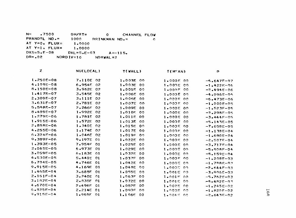
N= .7500 OH/RT= 0 CHANNEL FLOWPRANOTL NO.= 1000 BRINKMAN NO.= 0AT Y=0, FLUX= 1.0000AT Y=1, FLUX= 1.0000DXS=5.F-08 OXL=5.E-03 4=-115.DR=.02 NORDIV=10 NORWAL=2
Z NU(LOCAL) T(WALL) T(MFAN)
1.250E-08 7.110E 02 1.003E 00 1.000E 00 -6.647E-074.109E-08 6.954E 02 1.003E 00 1.000E 00 -1.422E-068.150E-08 3.962E 02 1.005E 00 1.001E 00 -2.494E-061.417E-07 3.545E 02 1.006E 00 1.000E 00 -4.096E-062.309E-07 3.111E 02 1.006E 00 1.000E 00 -6.473E-063.631E-07 2.781E 02 1.007E 00 1.001E 00 -1.000E-055.588F-07 2.266E 02 1.009E 00 1.000E 00 -1.523F-058.489E-07 1.992E 02 1.010E 00 1.000E 00 -2.299E-051.279E-06 1.781E 02 1.011E 00 1.000E 00 -3.4441-091.915E-06 1.572E 02 1.013E 00 1.001E 00 - 5.143F -052.858E-06 1.340E 02 1.015E 00 1.003F 00 -7.658E-054.255E-06 1.174E 02 1.017E 00 1.001E 00 -1.139E-046.324E -06 1.046E 02 1.019E 00 1.000E 00 -1.690E-049.389E-06 9.197E 01 1.022E 00 1.000F 00 -2.507F-041.393E-05 7.954F 01 1.025E 00 1.000E 00 -3.717E-042.065E-05 6.973E 01 1.029E 00 1.001E 00 -5.509E-043.059E-05 6.183E 01 1..032E 00 1.000E 00 -9.159E-044.530E-05 5.441E 01 1.037F 00 1.001E 00 -1.209F-036.704E-05 4.746E 01 1.042E 00 1.000E 00 -1.788E-039.915E-05 4.169E 01 1.048E 00 1.0017 00 - 2.644F -031.465E -04 3.685E 01 1.055E 00 1.001E 00 -3.906E-032.161E-04 3.240E 01 1.063F 00 1.001E 00 -5.762F-033.182E-04 2.835E 01 1.072E 00 1.001E 00 9.492E-074.670E -04 2.496E 01 1.082F 00 1.002E 00 -1.245E-026.925E-04 2.214E 01 1.093F 00 1.003F 00 -1.820E-029.919E-04 1 .965F 01 1.106E 00 1 .00AF 00 -2.641E-02

1.428E-03 1.748E 01 1.120E 00 1.006E 00 - 3.807E -022.033E-03 1.568E 01 1.136F 00 1.008E 00 -5.419F-022.850E-03 1.421E 01 1.152E 00 1.011E 00 -7.597E-023.917E-03 1.298E 01 1.170E 00 1.015E 00 -1.044E-015.261E-03 1.195E 01 1.188E 00 1.021E 00 -1.402E-016.880E-03 1.115E 01 1.207E 00 1.028E 00 -1.834E-018.751E-03 1.054E 01 1.225E 00 1.035E 00 -2.333E-011.083E-02 1.005E 01 1.242E 00 1.043E 00 -2.886E-011.306E-02 9.661E 00 1.259E 00 1.052E 00 -3.481E-011.539E-02 9.371E 00 1.275E 00 1.062E 00 -4.103E-011.779E-02 9.163E 00 1.290E 00 1.071F 00 -4.743E-012.023E-02 8.997E 00 1.303E 00 1.081E 00 -5.395E-012.270E-02 8.856E 00 1.317E 00 1.091F 00 -6.052E-012.518E-02 8.755E 00 1.329E 00 1.101F 00 -6.714E-012.767E-02 8.690E 00 1.341E 00 1.111E 00 -7.378E-013.017E-02 8.633E 00 1.352E 00 1.121E 00 -8.042E-013.266E-02 8.577E 00 1.364E 00 1.131E 00 -8.708E-013.516E-02 8.539E 00 1.375E 00 1.141E 00 -9.374E-013.766E-02 8.523E 00 1.385E 00 1.151E 00 -1.004E 004.016E-02 8.504E 00 1.396E 00 1.161F 00 -1.071E 004.266E-02 8.477E 00 1.407E 00 1.171E 00 -1.437E 004.516E-02 8.462E 00 1.417E 00 1.181E 00 - 1.204E 004.766E-02 8.462E 00 1.427E 00 1.191E on -1.271E on5.016E-02 8.457E 00 14437E 00 1.201F 00 -1.337E 00.5.266E-02 8.440E 00 1.448E 00 1.211E 00 -1.404E 005.516E-02 8.433E 00 1.458E 00 1.221E 00 -1.471E 005.766E-02 8.440E 00 1.468E 00 1.231E 00 -1.537E 006.016E-02 8.439E 00 1.478E 00 1.241F 00 -1.604E 006.266E-02 8.426E 00 1.488E 00 1.251E 00 -1.670E 006.516E-02 8.422E 00 1.498E 00 1.261E 00 -1.737F 006.766E-02 8.432E 00 1.508E 00 1.271E 00 -1.804F on7.016E-02 8.433E 00 1.518E 00 1.281E 00 -1.870F 007.266E-02 8.421E 00 1 .528F 00 1.291E 00 -1.937E 00

N= .5000 CHANNEL FLOWFULLY-DEV. VELOCITY AND UNIFORM FLUX=1.0DXS=5.E-08 DXL =5.E -03 4=-115.DR=.02 NDRDIV =10 NORWAL=2
Z NU(LOCAL) T(WALL) T(MFAN)
1.250E-08 7.537E 02 1.003F 00 1.000E 00 8.000E -074.109E-08 7.370E 02 1.003F 00 1.001E 00 -1.715F-068.150E-08 4.197E 02 1,005E 00 1.000F 00 -3.008E-061.417E-07 3.754E 02 1.005E 00 1.000E 00 -4.936E-052.309E-07 3.294F 02 1.006E 00 1.000E 00 -7.790E-053.631E-07 2.947E 02 1.007E 00 1.001E 00 -1.202E-055.588E-07 2.404E 02 1.008E 00 1.000F 00 -1.828E-058.489E-07, 2.112E 02 1.009F 00 1.000E 00 -2.755F-051.279E-06 1.888E 02 1.011E 00 1.000E 00 -4.131E-051.915E-06 1.666E 02 1.012E 00 1.000F 00 -6.168E-052.858E-06 1.422E 02 1.014E 00 1.000F 00 -9.185E-054.255E-06 1.246E 02 1.016E 00 1.000E 00 -1.366E-046.324E-06 1.108E 02 1.018E 00 1.000E 00 -2.028E-049.389E-06 9.748E 01 1.021E 00 1.001E 00 -3.008E-041.393E-05 8.431E 01 1.024E 00 1.001E 00 -4.461F-042.065E-05 7.387E 01 1.027E 00 1.000E 00 -6.611E-043.059E-05 6.545E 01 1.031F 00 1.000E 00 -9.793E-044.530E-05 5.757E 01 1.035F 00 1.000E 00 -1.450E-036.704E-05 5.0205 01 1.040F 00 1.000E 00 -2.146E-039.915E-05 4.410E 01 1.046E 00 1.001F 00 -3.173E-071.465E-04 3.898E 01 1.052E 00 1.001F 00 -4.688E-032.161E-04 3.426F 01 1.059F 00 1.001E 00 -6.9155-033.182E-04 2.9975 01 1.068E 00 1.001E 00 -1.018E-024.670E-04 2.636E 01 1.078E 00 1.0095 00 -1.494E-026.825E-04 2.336E 01 1.088E 00 1.003F 00 -7.184E-029.915E-04 2.072E 01 1.101E 00 1.004E 00 -3.173E-021.428E-032.0335-03
1.84151.649E
01
01
1.114E1.1295
0000
1.005E 001.0^BF 00
-4.569E-02-6.505E-02
1--,
oNN

2.850E-03 1.494E 01 1.145F 00 1.011E 00 -9.119E-023.917E-03 1.363E 01 1.162F 00 1.015E 00 -1.254F-015.261E-03 1.254E 01 1.181E 00 1.021E 00 -1.683F-016.880E-03 1.168E 01 1.199F 00 1.021E 00 -2.202E-018.751E-03 1.103E 01 1.216E 00 1.035E 00 -2.800E-011.083E-02 1.051E 01 1.234E 00 1.043F 00 -3.465E-011.306E-02 1.009E 01 1.250E 00 1.052E 00 -4.178E-011.539E-02 9.784E 00 1.266E 00 1.062E 00 -4.925F-011.779E-02 9.561E 00 1.280E 00 1.071F 00 -5.693E-012.023E-02 9.382E 00 1.294E 00 1.081E 00 -6.475E-012.270E-02 9.230E 00 1.308E 00 1.091E 00 -7.265E-012.518E-02 9.120E 00 1.320E 00 1.101E 00 -8.059E-012.767E-02 9.048E 00 1.332E 00 1.111E 00 -1.855E-013.017E-02 8.987E 00 1.343E 00 1.121E 00 -9.653F-013.266E-02 8.926E 00 1.355E 00 1.131E 00 -1.045E 003.516E-02 8.884E 00 1.366E 00 1.141E 00 -1.125E On3.766E-02 8.865E 00 1.376E 00 1,151E 00 -1.205E 004.016E-02 8.844E 00 1.387E 00 1.161E 00 -1.285E 004.266F-02 8.814E 00 I.398F 00 1.17IE 00 -1.365E On4.516E-02 8.798E 00 1.408E 00 1.181F 00 -1.445E 004.766E-02 8.797E 00 1.418F 00 1.191E 00 -1.525E 005.016E-02 8.790E 00 1.428E 00 1.201F 00 -1.605E 005.266E-02 8.773E 00 1.439E 00 1.211E 00 -1.685E 005.516E-02 8.765E 00 1.449E 00 1.221E 00 -1.765E 005.766E-02 8.771E 00 1.459E 00 1.231F 00 -1.845E 006.016E-02 8.770E 00 1.469F 00 1.241F 00 -1.925F on6.266E-02 8.757E 00 1.479F 00 1.251F 00 -2.005E 006.516E-02 8.753E 00 1.489E 00 1.261E 00 -2.085E 006.766E-02 8.762E 00 1.499E 00 1.271F 00 -2.165E 007.016E-02 8.763E 00 1.509E 00 1.281E 00 -2.245E 007.266E-02 8.751E 00 1.519E 00 1.291E 00 -2.325E on

N= .2500 CHANNEL FLOWFULLY-DEV. VELOCITY AND UNIFORM FLUX=I.0DR=.02 NORDIV=10 NORWAL=2DXS=5.E-08 DXL=5.E-03 A=-115.
Z NU(LOCAL) T(WALL) T(MEAN)
1.250E-08 8.589E 02 1.002E 00 1.000E 00 -1.200E-064.109E-08 8.398E 02 1.002E 00 1.001F 00 -2.572F-068.150E-08 4.777E 02 1.004E 00 1.000F 00 -4.512E-061.417E-07 4.269E 02 1.005E 00 1.000E 00 -7.404E-062.309E-07 3.739E 02 1.005E 00 1.000E 00 -1.168E-053.631E-07 3.351E 02 1.006E 00 1.000E 00 -1.803E-055.588E-07 2.745E 02 1.007E 00 1.003E 00 -2.742F-058.489E-07 2.410E 02 1.008F 00 1.001E 00 -4.135E-051.279E-06 2.147E 02 1.009E 00 1.000E 00 -6.197E-051.915E-06 1.897E 02 1.011E 00 1.000F 00 -9.252E-052.858E-06 1.622E 02 1.012E 00 1.003E 00 -1.378F-044.255E-06 1.420E 02 1.014E 00 1.000E 00 -2.048E-046.324E-06 1.261E 02 1.016F 00 1.000E 00 -3.042E-049.389F-06 1.109E 02 1.018E 00 1.000E 00 -4.513E-041.393E-05 9.598E 01 1.021E 00 1.000E 00 -6.691E-042.065E-05 8.399F 01 1.024E 00 1.000F 00 -9.915F-043.059E-05 7.425E 01 1.027E 00 1.000E 00 -1.469E-034.530E-05 6.522E 01 1.031F 00 1.000E 00 -2.175F-036.704E-05 5.684E 01 1.035E 00 1.400E 00 -3.219E-039.915E-05 4.987E 01 1.040E 00 1.001F 00 -4.760E-031.465E-04 4.403E 01 1.046F 00 1.001E 00 -7.032F-032.161F-04 3.870E 01 1.053E 00 1.001E 00 -1.037E-023.182E-04 3.384E 01 1.060E 00 1.001F 00 -1.527E-024.670E-04 2.972E 01 1.069E 00 1.002E 00 -2.242E-026.825E-04 2.625E 01 1.079F 00 1.003E 00 -3.276F-029.915E-04 2.322E 01 1.090E 00 1.004E 00 -4.759F-021.428E-03 2.058E 01 1.103E 00 1.005E 00 -6.854E-022.033F-03 1.839E 01 1.117E 00 1.00rzr: nn -9.757F-02

2.850E-03 1.660E 01 1.132E 00 1.011F 003.917E-03 1.510E 01 1.148E 00 1.015F 005.261E-03 1.386E 01 1.165E 00 1.021E 006.880E-03 1.288E 01 1.183E 00 1.029E 008.751E-03 1.213E 01 1.200E 00 1.035E 001.083E-02 1.153E 01 1.217F 00 1.043E 001.306E-02 1.105E 01 1.233E 00 1.052F 001.539E-02 1.069E 01 1.249E 00 1.062E 001.779E-02 1.043F 01 1.263E 00 1.071E 002.023E-02 1.022E 01 1.277F 00 1.081E 002.270E-02 1.004E 01 1.290F 00 1.091E 002.518E-02 9.910E 00 1.303E 00 1.101E 002.767F-02 9.820E 00 1.314E 00 1.111E 003.017E-02 9.745E 00 1.326E 00 1.121F on3.266E-02 9.673E 00 1.338E 00 1.131F 003.516E-02 9.623F 00 1.349E 00 1.141E 003.766E-02 9.595E 00 1.359E 00 1.151E 004.016E-02 9.568E 00 1.370E 00 1.161F 004.266E-02 9.534E 00 1.381E 00 1.171E 004.516E-02 9.513E 00 1.391E 00 1.181E 004.766E-02 9.508E 00 1.401F 00 1.191F 005.016E-02 9.499E 00 1.411F 00 1.201E 005.266E-02 9.480E 00 1.422E 00 1.211E 005.516E-02 9.471E 00 1.432E 00 1.221F 005.766E -02 9.474F 00 1.442E 00 1.231E 006.016E-02 9.472E 00 1.452E 00 1.241E 006.266E-02 9.459E 00 1.462E 00 1.251E 006.516E-02 9.454E 00 1.472F 00 1.261F 006.766F -02 9.461E 00 1.482E 00 1.271E 007.016E-02 9.462E 00 1.492F 00 1.291E 007.266E-02 9.451E 00 1.502E 00 1.291E 00
-1.368E-01-1.880E-01-2.525F-01-3.307F-01-4.200E-01-5.197E-01-6.267E-01- 7.387E -01-9.540E-01-9.713F-01-1.090E 00-1.209E 00-1.329E 00-1.448E 00-1.568E 00-1.69nF 00-1.808F 001.928E 00
-2.049E 00-2.168F 00-2.289F 00-2.408E 00-2.528F 00
:::;76:: Z;-2.889E 00
:33:11= 00(0)-3.248E 00-3.368E 00-3.489F 00
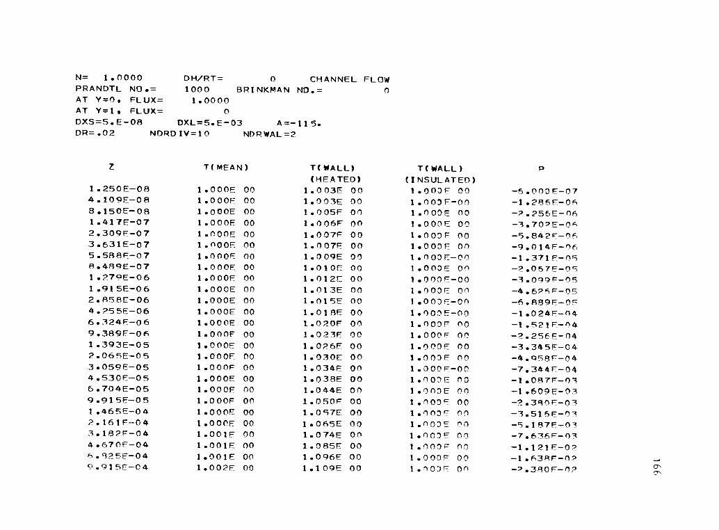
N= 1.0000 DH/RT= 0 CHANNEL FLOWPRANDTL NO.= 1000 BRINKMAN NO.= 0AT Y=0* FLUX= 1.0000AT Y=ls FLUX= 0DXS=5.E-08 DXL=5*E-03 4=-115.DR=.02 NDRDIV=10 NDRWAL=2
Z T(MEAN) T(WALL) T(WALL) P(HEATED) (INSULATED)
1.250E-08 1.000E 00 1.003E 00 1.000E 00 -6.000E-074.109E-08 1.000E 00 1.003E 00 1.003E-00 -1.286E-068.150E-08 1.000E 00 1.005E 00 1.000E 00 -2.256E-061.417E-07 1.000E 00 1*006F 00 01.00E 00 -3.7025-062.309E-07 1.000E 00 1.007F 00 1.000E 00 -5.842E-063.631E-07 1.000E 00 1.007E 00 1.000E 00 -9.014E-065.588F-07 1.0005 00 1.009E 00 1.000E-00 -1.371E-058.489E-07 1.000E 00 1.010F 00 1.000E 00 -2.067E-051.279E-06 1.000F 00 1.012E 00 1.000E-00 -3.099E-051.915E-06 1.000E 00 1.013E 00 1.0005 00 -4.626E-052.858E-06 1.000E 00 1.015E 00 1.000E-00 -6.Pf719E-04.255E-06 1.000F 00 1.018E 00 1.00)E-00 -1.024E-046.324E-06 1.000E 00 1.020E 00 1.0005 00 -1.521E-049.389F-06 1.000E 00 1.023E 00 1.000E 00 -2.256E-041.393E-05 1.000E 00 1.026F 00 1.000E 00 -3.345E-042.065E-05 1.000E 00 1.030E 00 1.000E 00 -4.958E-043.059E-05 1.000F 00 1.034E 00 1.0005-00 -7.344E-044. 530E-05 1.000E 00 1.038E 00 1.000E 00 -1.087E-036.704E-05 1.000E 00 1.044E 00 1.000E 00 -1.609E-039.915E-05 1.000F 00 1.050E 00 00 -2.380E-071.465E-04 1.000E 00 1.057E 00 ::Z0);: 00
.12.161E-04 1.000E 00 1.065E 00 1.0035 00 -.783:: ;3.182E-04 1.001E 00 1.074E 00 1.001F 00 -7.636E-034.670E-04 1.001E 00 1.0855 00 1.0007 00 -1.121E-026.825E-04 1.001E 00 1.0965 00 1.0005 00 -1.638E-029.9155-04 1.0025 00 1.1095 00 1.0005 00 -2.380E-02
167
0.4-4
0000 00
000.!
0.40.0
C C
C cc C
c C. C
cc c.O
0CC
000C0.0C
000C0C
0C00C
00000CC
CC
0CU
.ILI
LL, L LiiU
.U
.112
L ILIU
.1U
.IL U
IL.
ILIU
.'U
.ILI
lL.iLU
U. W
IL U. L Li
r-cr,
(.1/4!re, .0CC
Ore,O
CO
CC
40000.,MO
NC
O404 444 4 4 4444 4
C a C
CT
r- lC +
4 4 4 4 r re r Ir1c.!
co 4 0 tr: N co 4 0 rG
N cc:, 4
4 Do
Ct 4 N
%c';
in1,-g
NC
) N C
CC
Li N C
O 4
Li C C
00 N c,
frre., 4 kr
kr c-**
OO
r! 4 kr!c!,
c).!C
t.'rri
Ir 44 U
lfl h N
CC
.C
TC
T e"
*-4*", r 04
004.404
040000 r 01
II
II
II
IIII II
II
II
II
III
III
II
I1 11111
coccccocCccocccccocc00ccoccocc0c
cocCoccoccoccoccc000cocccoccoccoc
ILLI U
J LLU
..!LI
U.
LIU
.U
.'Lt.'
U.)
IL'U
.'L.'
IL.LI.'
U.'
LIU
.iU
.L i
U.1
LI ILU
'o
0 0 0. C C
) 0. 0.01
.04C
t.trl 4 in
Li
cr.cr.
0. of%
,e,0-4
retN
. 0 1(1kr. 0
C C
c O c o 0 0 0 0
0000000 0 0 0 C
0 .4 .0 .4N
e4; Nrn re,
reiO
0CC
c0c0C.C
OC
C.C
C.00000C
0000CC
000CC
O.00
00004
4.4401
.41.1
001.0
0440040 r 0.4
0.400
0.1 r OO
0.0 .00
4.0044
94.1041
.1 v.14.
O 00000000000000000000000000000000
00000000000000000000000000000000
0LI
L.1.4., W
W W
U..1
LI LIILI
11.1LI LI LI LU
W U
. LI U. kl LI W
1.1,U
U.1 W
W U
.iU
..1II)
LI1.1.1
U-1
4 c 43 4 M N
0 MI
C7, N
4 IPIn
kr!re) 0-
Ct.
h.N
o h 4 r r-st
Rt
11/4.-C
Tr) 4 tr)
CC
a 0 cvcr,
CP, a .4 (V
CV
rC1
4t IP 01.0
1"..c0
CC
(:)'
04 00 00N
N N
N N
Nrm
.rn
tr,rn In In
rn. 4 at 4 at 4 4 4 4 4 4 at 4 <I'
00 04 r r 44440441 r 404 .4 M
..... 404.4 .4
41110 M .41 r 0441
0041.4 .1 4. r 4014
000.41
O C
.) 0 0 C.) 0 0 C
0 0 0 C C
C C
O 0 0 0 0 0 0, 0 O
C 0
C 0
0 0 0 00.
00000000000-00000000000.coc0 0 cocccoLLi
U.) W
LI1 W LU
W LL) W
W LL1
LU W
ILILC
LU IL W
LL1U
IIli W L LI
U.I
ILI W W
W LI LI Li
LLre) 4 kt.,
CO
a) N t4) r +
.0 r kr) 0 U") 0 If) 0 IS
) 0 LO 0 LO
0 tJ C 1.0 0 It) 0 LC
0 LOO
0 0 0 r 0. 0. N N
Ir1re) 4 4 LO
U i
t.0%
.0 h r- CO
CO
0 0 .0 0. N cj In
re) 4 4O
C 0 C
4C O
CC
00 00 0000 C000 000 0.0
0.411.0
0.414.1
,r41.4 r 0001 r 4.4
0.44.4
044410144
4.044.4 r r 00
.444044
004404
.4 .41004
.1 .1 .4 04 040.4
0.44.4 r 9401
r) rf)re)
Cr)
rf) M N
c\kcu N
N N
N N
N N
N N
NN
NN
NN
NN
NN
N N
N N
O 0 0 0 0 0 0 0 0 0 0 0 0 0 0 0 0 0 0 0 0 0 0 0 0
0 0 0 0 0 0 C)
WW
WW
1.1.3U
I1.0
U.: L
U W
LL
: U U
J Lu W
LL
Ili UI IL
U.:
L.) W W
LU W
11.1U
.)LI Li
U.:
ILL.3
CO
re) G h 00 0
rn 4) CT
0, r9 o CO
N. N
k7k.0
kCk0
4;)4; 4;
4.)4.)
NO
4)N
4) CO
IP C
O 0 r)
r*- N+
-4tC
4 IC 0. 0 0. 0 0. 0 r
0.4
CC
O N
- 0 rnN
. C N
r-C
'. N U
5 N 0 N
if)N
. O N
c N L
C N
ON
...... a0.4 N
N r)
tr,-4 -4 -1 r N
(V N
C\I
rnre)
inrr)
4tst 4 4 LO
If)

N= 1.0000 OH/RT= 5 CHANNEL FLOWPRANDTL NO.= 1000 BRINKMAN NO.= 0AT Y=0, FLUX= 1.0000AT Y=1, FLUX= 0DXS=5.E-08 DXL=5.E-03 A=-115.DR=.02 NORDIV=10 NDRWAL=2
NU(LOCAL) T(WALL) T(MEAN)
1.250E-08 1.000E 00 1.003E 00 1.000E 00 -5.974E-074.109E-08 1.000E 00 1.003E 00 1.000E 00 -1.275F-068.150E-08 1.000F 00 1.005E 00 1.000E 00 -2.237F-061.417E-07 1.000E 00 1.006E 00 1.000F 00 -3.668F-062.309E-07 1.000E 00 1.007E 00 1.100F on -5.786E-063.631E-07 1.000F 00 1.007E 00 1.000E-00 -8.929E-065.588E-07 1.000E 00 1.009E 00 1.000E-00 -1.358E-058.489E-07 1.000E 00 1.010E 00 1.000E 00 -2.048F-091.279F-06 1.000E 00 1.011E 00 1.000E 00 -3.069F-051.915E-06 1.000E 00 1.013E 00 1.000E 00 -4.581F-052.858E-06 1.000E 00 1.015E 00 1.000E-00 -6.825E-054.255E-Of, 1.000E 00 1.017E 00 1.000F 00 -1.014F-046.324E-06 1.000E 00 1.019E 00 1.000F 00 -1.506E-049.389E-06 1.000E 00 1.022E 00 1.000E-00 -2.235E-041.393F-05 1.000F 00 1.025F 00 1.000E-00 -3.312F-042.065E-05 1.000E 00 1.029E 00 1.000E 00 -4.907F-043.059E-05 1.000F 00 1.032E 00 1.000E 00 -7.265E-044.530E-05 1.000E 00 1.037E 00 1.001 -00 -1.075E-036.704E-05 1.000E 00 1.042E 00 1.001F 00 -1.588E-039.915E-05 1.000E 00 1.048E 00 1.001F 00 -2.344E-071.465E-04 1.000E 00 1.054E 00 1.000F 00 -3.454F-032.161E-04 1.000E 00 1.061E 00 1.000F 00 -5.076E-033.192E-04 1.001E 00 1.070E 00 1.000F 00 -7.437F-034.670E-04 1.001E 00 1.079F 00 1.001E nn -1.085F-026.925E-04 1.001E 00 1.089F 00 1.000F 00 -1.574E-029.915F-04 1.002E 00 1.101F 00 1.00707 Pr'' -2.264F-02

1.428E-03 1.003E 00 1.114F 00 1.000E-00 -3.224E-022.033E-03 1.004E 00 1.127E 00 1.000E 00 -4.528F-022.850E-03 1.006E 00 1.142E 00 1.00E 00 -6.251E-023.917E-03 1.008E 00 1.158F 00 1.000F 00 -8.448E-025,261E-03 1.011E 00 1.175E 00 1.107F 00 -1.114F-016.880E-03 1.014E 00 1.191F 00 1.000F 00 -1.479E-018.751E-03 1.0185 00 1.207E 00 1.001E 00 -1.784E-011.083E-02 1.022E 00 1.2235 00 1.0005 00 -2.1675-011.306E-02 1.026E 00 1.238E 00 1.000F 00 -2.569E-011.539F-02 1.031E 00 1.2525 00 1.0015 00 -2.980E-011.779E-02 1.036E 00 1.265E 00 1.0007 00 -3.394E-012.023E-02 1.0415 00 1.278E 00 1.000E 10 -3.806E-012.270E-02 1.046E 00 1.2905 00 1.005 00 -4.215E-012.518E-02 1.0505 00 1.300E 00 1.001E 00 -4.620E-012.767E-02 1.055E 00 1.311E 00 1.0015 00 -5.019E-013.017F-02 1.0615 00 1.321E 00 1.0025 00 -5.412E-013.266E-02 1.066E 00 14,331F 01 1.0025 00 -5.799E-013.516E-02 1.070E 00 1.339E 00 1.0035 00 -5.1Fk7F-013.766E-02 1.0755 00 1.3485 00 1.004E 00 -6.560E-014.016E-02 1.0815 00 1.3575 00 1.0055 00 -6.929E-014.266E-02 1.0865 00 1.366F 00 1.007E 00 -7.293F-014.516E-02 1.0895 00 1.372E 00 1.009E 00 -7.6555-014.766E-02 1.0955 00 1.379F 00 1.011F 00 -8.012E-015.0165-02 1.1025 00 1.3905 00 1.013F 00 -8.358E-015.2665-02 1.107E 00 1.3985 00 1.115F 00 -8.698E-015.516E-02 1.108E 00 1.401E 00 1.0175 00 -9.0405-015.766E-02 1.113E 00 1.407E 00 1,4120F 00 -9.378E-016.016E-02 1.124E 00 14,4205 00 1.023E 00 -9.699E-016.266E-02 1.129E 00 1.429E 00 1.0255 00 -1.001E 006.5165-02 1.1265 00 1.426E 00 1.0295 00 -1.0345 006.766F-02 1.129F 00 1.429E 00 1.032E 00 -1.066F 007.016E-02 1.147E 00 1.448E 00 1.035E 00 -1.096F 007.266E-02 1.154F 00 1.463F 00 1.037F 00 -1.124E 0/