Embed Size (px)
Citation preview

December 2002, ver. 1.1 Application Note 255
Guidelines to MigratingSpartan Designs
to Cyclone Designs
Altera Corporation 1
Introduction Altera's new Cyclone™ devices are the first FPGAs that are low cost by design—the best choice for price-sensitive, volume-driven applications. The Cyclone family has a die-efficient architecture specifically designed to bridge the convergence of high-volume applications with a cost-sensitive solution.
This application note discusses the migration of designs targeting Xilinx Spartan-IIE devices to designs compatible with Altera’s Cyclone devices. These steps include information on converting design elements specific to the Spartan-IIE family into Cyclone megafunctions, along with general device migration guidelines.
This application note is meant to assist you when migrating Spartan-IIE designs to Cyclone designs. For more information on Cyclone architectural features, see the Cyclone FPGA Family Data Sheet. For more information on compiling a design in the Quartus II software, see the Quartus II Software Quick Start Guide For Quartus II Software Version 2.1 and the Quartus II Tutorial by selecting Tutorial (Help menu) within the Quartus II software. For more information on Altera megafunctions, see the Altera web site (www.altera.com).
1 This application note assumes you are familiar with the Spartan-IIE architecture and features as well as the Quartus II software.
This application note is based on features in the Xilinx ISE 4.2itool and the Quartus II tool version 2.1 SP1.
AN-255-1.1

AN 255: Guidelines to Migrating Spartan Designs to Cyclone Designs
Table of Contents
Introduction .......................................................................................................1Table of Contents ..............................................................................................2Conversion Flow...............................................................................................3
Step 1: Identify Design Hierarchy ..........................................................3Step 2: Identify Spartan-IIE Specific Primitives & Cores ....................3Step 3: Generate Cyclone Equivalents to Spartan-IIE Primitives ......4Step 4: Migrate Spartan-IIE Design Constraints into Quartus II
Timing Constraints ...........................................................................4Step 5: Compile in the Quartus II Software ..........................................4Step 6: Verify the Conversion..................................................................4
Memory & Resources .......................................................................................4Design Hierarchy ..............................................................................................6Identify Spartan-IIE Primitives & Modules ..................................................6Generate Cyclone Equivalents to Spartan-IIE Primitives ...........................6
Converting Primitives ..............................................................................7Global Clock Buffer ..........................................................................7Clock Delay Locked Loop Buffer....................................................9D FlipFlop ........................................................................................10Global Input Buffer.........................................................................12Single & Multiple Input Buffers....................................................12Bidirectional Buffer.........................................................................13Single & Multiple Output Buffers ................................................17Selectable I/O Interfaces................................................................18Static RAM .......................................................................................20Single-Port Synchronous Block RAM ..........................................25Dual-Port Synchronous Block RAM ............................................2716-Bit Shift Register Look-up-Table .............................................31
Converting CORE Generator System Modules ..................................33Creating Dual-Port Memory .........................................................34Creating FIFO Buffers ....................................................................38Creating Multipliers .......................................................................40altmult_add Megafunction............................................................42
Migrate Spartan-IIE Design Constraints into the Quartus II Software...43Timing Constraints .................................................................................44Placement Constraint .............................................................................49
Compile in the Quartus II Software .............................................................49Verify the Conversion ....................................................................................49Conclusion .......................................................................................................49References ........................................................................................................50
2 Altera Corporation

AN 255: Guidelines to Migrating Spartan Designs to Cyclone Designs
Conversion Flow
The conversion flow from a Spartan-IIE to a Cyclone design is a six-step process, as shown in Figure 1.
Figure 1. Conversion Flow from a Spartan-IIE to an Altera Design
Step 1: Identify Design Hierarchy
Identifying a design’s hierarchy simplifies the conversion process by allowing the conversion of each branch of hierarchy to be performed separately, thus enabling a “divide-and-conquer” methodology in the conversion process. This process will also help you identify each Spartan-IIE primitive and core.
Step 2: Identify Spartan-IIE Specific Primitives & Cores
This step identifies the various Spartan-IIE specific cores and primitives and isolates them from generic VHDL or Verilog HDL design code, such as state machines and control logic. You must convert these cores and primitives to Cyclone functions.
Identify design hierarchy
Identify Spartan-IIE specificprimitives and cores
Compilation in theQuartus II software
Verification of conversion
Generate Cyclone equivalentto Spartan-IIE primitive
Migrate Spartan-IIE design constraintsto the Quartus II software
Altera Corporation 3

AN 255: Guidelines to Migrating Spartan Designs to Cyclone Designs
Step 3: Generate Cyclone Equivalents to Spartan-IIE Primitives
You should convert all the cores and primitives to Cyclone-specific functions. You can use the MegaWizard Plug-In Manager tool to customize megafunctions optimized for the Cyclone family of devices. This application note provides information on generating megafunctions using the MegaWizard Plug-In Manager.
1 For more information on the MegaWizard Plug-In Manager see the Altera web site (www.altera.com).
Step 4: Migrate Spartan-IIE Design Constraints into Quartus II Timing Constraints
Spartan-IIE designs have both timing constraints and location constraints. You should convert the timing constraints to compatible Quartus II timing constraints. However, you do not need to convert location constraints because Spartan-IIE device locations do not have any correlation to Cyclone device locations.
Step 5: Compile in the Quartus II Software
After you convert all Spartan-IIE design elements to Cyclone design elements, you can compile the design in the Quartus II software.
1 For more information on compiling designs in the Quartus II software, refer to the Quartus II Tutorial by selecting Tutorial (Help menu).
Step 6: Verify the Conversion
Verifying the conversion ensures that the design can run in a Cyclone device. Verification can focus on functionality, timing, or both, and be limited to converted design elements or the entire design.
Memory & Resources
The Cyclone device family offers features for designs that require high performance, ease of Intellectual Property (IP) integration, and fast time-to-market, but also are sensitive to high-volume, cost-sensitive design requirements. This section provides a brief overview of the Cyclone architecture and Spartan-IIE equivalent.
1 See the Cyclone FPGA Family Data Sheet for more information.
4 Altera Corporation

AN 255: Guidelines to Migrating Spartan Designs to Cyclone Designs
The Cyclone memory structure is composed of a dedicated array of M4K memory blocks that simplifies the creation of memory-related functions. A single Cyclone device can provide up to 288 Kbits of memory. M4K RAM blocks are true dual-port memory blocks with 4 Kbits, plus parity (4,608 bits). These M4K blocks provide dedicated true dual-port, simple dual-port, or single-port memory blocks up to 36-bits wide, at up to 200 MHz.
The Spartan-IIE family offers two types of memory: Distributed RAM and Block RAM. The Distributed RAM is implemented in the device configurable logic blocks (CLBs), whereas the Block RAM is a dedicated memory structure. Each Block RAM consists of 4,096 memory bits. The largest Spartan-IIE device offers a total of 96K bits of Distributed RAM, and 64K bits of Block RAM.
The Cyclone family offers 2,910 to 20,060 LEs complemented with Cyclone’s support for multiple IP megafunctions. Table 1 provides a summary comparing the smallest and largest devices in both Cyclone and Spartan-IIE families.
Notes to Table 1:(1) This is the number of LE-equivalent elements in Spartan-IIE devices.(2) Total memory bits lists the total available memory on the Spartan-IIE device, including both Distributed and Block
RAM bits.
Cyclone devices feature phase locked loops (PLLs), which are similar to Spartan-IIE delay-locked loops (DLLs). Cyclone devices also feature a global clock network for clock management. Cyclone PLLs offer clock multiplication and division, phase shifting, programmable duty cycle, and external clock outputs, allowing system-level clock management and skew control.
f See AN 251: Using PLLs in Cyclone Devices for more information on Cyclone PLL features.
Table 1. Cyclone & Spartan-IIE Resource Summary
Resources Cyclone EP1C3
Spartan-IIE XC2S50E Cyclone EP1C20
Spartan-IIE XC2S300E
LEs 2,910 1,536 (1) 20,060 6,144 (1)
Total memory bits (Kbits) 58.5 56 (2) 288 160 (2)
Altera Corporation 5

AN 255: Guidelines to Migrating Spartan Designs to Cyclone Designs
Design Hierarchy
By identifying a design’s hierarchy of cores, you can use a “divide-and-conquer” process to convert the Spartan-IIE design to a Cyclone design. Using this process, you break down the Spartan-IIE design hierarchy by identifying the cores that make up the design, including the top level and lower-level cores. Typically, a majority of the Spartan-IIE specific design elements are located in the lower-level of a Spartan-IIE’s design hierarchy.
Identify Spartan-IIE Primitives & Modules
Designs targeting the Spartan-IIE family will contain design elements that are specific to this family only and are not compatible with the Cyclone family. These design elements are comprised of Spartan-IIE primitives and CORE Generator System functions.
f The Converting Primitives section on page 7 and the Converting CORE Generator System Modules section on page 33 describe how to identify and convert these design elements into megafunctions available for the Cyclone architecture.
You can identify Spartan-IIE primitives by opening the design in a text editor and performing a search on the primitive name. Spartan-IIE primitives have a standard naming convention (e.g., SRL16). The Primitive section describes typical Spartan-IIE primitives and how to migrate these primitives to Cyclone designs.
In addition to Spartan-IIE primitives, you must also identify Spartan-IIE CORE Generator System modules. You can use synthesis tools such as the LeonardoSpectrum™ software and Synplify software to identify these modules. Each synthesis tool generates a summary report file detailing the various synthesis results. The summary report file contains a section that includes all modules identified during the synthesis step. The Converting CORE Generator System Modules section describes modules created by the CORE Generator System and explains how to migrate these modules to Cyclone designs.
Generate Cyclone Equivalents to Spartan-IIE Primitives
Once you identify the Spartan-IIE primitives and CORE Generator System modules, you must replace these design elements with Cyclone device megafunctions. The Quartus II MegaWizard Plug-In Manager can help you with the migration by creating Altera megafunctions.
You can use the MegaWizard Plug-In Manager to create megafunctions, including library of parameterized modules (LPM) functions, to instantiate in a design and set megafunction parameters. The MegaWizard Plug-In Manager will ask for parameter values required by the design (e.g., port widths and depths, optional ports such as enables and presets) to create a unique instance of the megafunction for your design.
6 Altera Corporation

AN 255: Guidelines to Migrating Spartan Designs to Cyclone Designs
The MegaWizard Plug-In Manager automatically generates a Component Declaration File (.cmp) that can be used in VHDL Design Files (.vhd) and an Altera hardware description language (AHDL) Include File (.inc) to use in Text Design Files (.tdf) and Verilog HDL Design Files (.v). The MegaWizard Plug-In Manager also creates a sample instantiation template with the extension _inst.tdf for AHDL designs, _inst.vhd for VHDL designs, and _inst.v for Verilog HDL designs. The MegaWizard Plug-In Manager also creates a sample module declaration file _bb.v for Verilog HDL designs. The sample module declaration files contain module and port declarations for the megafunction variation.
Converting Primitives
Primitives are the basic building blocks in a Spartan-IIE-based device. They implement various dedicated functions within the device, such as shift registers, and specify I/O standards for the Spartan-IIE I/O pins. Primitives have fixed ports and are not customizable.
Primitives can be easily identified because their names are standardized. Use one of the following methods to convert Spartan-IIE primitives.
■ Replace the primitive with an equivalent Cyclone primitive■ Replace the primitive with a user assignment with the Quartus II
Assignment Organizer■ Replace the primitive with an equivalent Cyclone function using the
MegaWizard Plug-In Manager
The following section discusses commonly used primitives and how to implement the equivalent functionality in Cyclone devices.
Global Clock Buffer
The BUFG primitive is a global clock buffer in the Spartan-IIE device which distributes high fan-out clock signals throughout the device. All Spartan-IIE devices support four global clock buffers. Figure 2 shows the block diagram for this primitive.
Figure 2. BUFG Primitive
IBUFG BUFG
I O I O
Altera Corporation 7

AN 255: Guidelines to Migrating Spartan Designs to Cyclone Designs
You can use the Altera GLOBAL primitive to replace the BUFG primitive in a Spartan-IIE design when targeting a Cyclone device. An alternative to instantiating a GLOBAL primitive is to enable ‘Auto Global Clock’ in the Assignment Organizer in the Quartus II software. This setting allows the Quartus II software to place signals onto the global clock network. You can also make global assignments for individual clocks through the Quartus II Assignment Organizer in the Assignment Categories box, as shown in Figure 3.
Figure 3. Global Declaration in the Assignment Organizer
Table 2 lists the Spartan-IIE ports for the BUFG primitive and the corresponding Cyclone device ports.
Table 2. Port Description of the BUFG Primitive
Port Description Spartan-IIE Port Cyclone Port
Input to buffer I a_in
Output from buffer 0 a_out
8 Altera Corporation

AN 255: Guidelines to Migrating Spartan Designs to Cyclone Designs
Clock Delay Locked Loop Buffer
The BUFGDLL primitive is a DLL used for clock skew management within the Spartan-IIE device. The BUFGDLL output is a 1× clock aligned with the BUFGDLL input. The primitive manages skew through the internal feedback from the BUFGDLL output. Figure 4 shows the relationship between BUFGDLL and the CLKDLL.
Figure 4. BUFGDLL Primitive
When the altpll megafunction is in normal mode, it can provide the same features as the BUFGDLL primitive, and the clock driven out of the PLL is aligned with the input clock of the PLL. Figure 5 shows a Cyclone PLL with a 200-MHz input clock frequency.
f For more information on using the altpll megafunction, see the altpll Megafunction User Guide.
INCLK
BUFGDLL
CLKFB
CLKDLL
CLK0I O
Altera Corporation 9

AN 255: Guidelines to Migrating Spartan Designs to Cyclone Designs
10 Altera Corporation
Figure 5. Cyclone Device BUFGDLL Equivalent
Table 3 lists the Spartan-IIE ports for the BUFGDLL primitive and the corresponding Cyclone device ports.
D FlipFlop
The FD primitive is a single simple flipflop with input D and output Q. Figure 6 shows the FD primitive schematic.
Figure 6. FD Primitive
You can replace the Spartan-IIE FD primitive with Altera’s D flipflop (lpm_ff) megafunction.
Table 3. BUFGDLL Primitive Port Description
Port Description Spartan-IIE Port Cyclone Port
Input to PLL I inclk0
Output from buffer 0 c0
DC
Q

AN 255: Guidelines to Migrating Spartan Designs to Cyclone Designs
Table 4 lists the Spartan-IIE ports for the FD primitive and the corresponding Cyclone device ports.
Table 5 lists the variants of the FD primitive with various control signals.
1 You can use the DFFE primitive if any combination of clock enable, clear, or preset is required for a register or enable these optional ports in the lpm_ff megafunction.
Table 4. Port Description of the BUFG Primitive
Port Description Spartan-IIE Port Cyclone Port
Data input to DFF D data
Data output from DFF Q q
Clock to DFF C clock
Table 5. FD Primitive Variants
Xilinx Primitive Name Description
FD_1 Negative-edge-triggered DFF
FD4, FD8, FD16 Bus of flipflop configured as 4, 8, and 16 flipflops
FDCE DFF with clock enable and asynchronous clear
FDCE_1 Negative-edge-triggered DFF with clock enable and asynchronous clear
FD4CE, FD8CE, FD16CE Flipflop bus configured as 4, 8, and 16 flipflops with clock enable and asynchronous clear
FD4RE, FD8RE, FD16RE Flipflop bus configured as 4, 8, and 16 flipflops with clock enable and synchronous reset
FDC DFF with asynchronous clear
FDC_1 Negative-edge-triggered DFF with asynchronous clear
FDCP DFF with asynchronous preset and clear
FDCP_1 Negative-edge-triggered DFF with asynchronous preset and clear
FDCPE DFF with clock enable and asynchronous preset and clear
Altera Corporation 11

AN 255: Guidelines to Migrating Spartan Designs to Cyclone Designs
Global Input Buffer
The IBUFG primitive is an input clock buffer for connecting to a BUFG or a CLKDLL and can only be driven by an IPAD. There is an additional timing delay when routing to a DLL clock input without an IBUFG. The Spartan-IIE device has four clock pads available for input clocks or regular I/O pins. Instantiating an IBUFG in either a VHDL or Verilog HDL design indicates that a clock feeds this primitive. Figure 7 shows the schematic for the IBUFG primitive.
Figure 7. IBUFG Primitive
Use the Altera GLOBAL primitive to replace the IBUFG primitive. See “Global Clock Buffer” on page 7 for more information on the Altera GLOBAL primitive.
If the IBUF primitive feeds a BUFG primitive, you must delete one of these and replace the other with Altera’s GLOBAL primitive.
Single & Multiple Input Buffers
The IBUF, IBUF4, IBUF 8, and IBUF16 primitives connect the output of either an IPAD or an IOPAD to the internal circuit of the Spartan-IIE device. Figure 8 shows the IBUF primitive for a Spartan-IIE device. The IBUF primitive can be either 4-, 8-, or 16-bits wide, and the width is signified by the numerical suffix at the end of the primitive. For example, IBUF4 instantiates a 4-bit wide primitive.
Figure 8. The IBUF Primitive
IBUFG BUFG
I O I O
IBUF
I O
12 Altera Corporation

AN 255: Guidelines to Migrating Spartan Designs to Cyclone Designs
You do not need to instantiate an I/O pad primitive or megafunction for Cyclone designs written in VHDL or Verilog HDL to infer I/O pads. When synthesizing in a third-party tool, you can infer I/O pads in the generated netlist file or have the Quartus II software infer them. The Quartus II software will map Cyclone device pins to their corresponding signals in the design. As a result, you do not need an equivalent to the IBUF primitive in a Cyclone design. After removing the IBUF primitive, ensure that the pin is connected to the correct signal in the design.
Bidirectional Buffer
The IOBUF primitive is a bidirectional buffer for the Spartan-IIE device. This primitive has input ‘I,’ output ‘O,’ bidirectional line ‘IO,’ and enable ‘T,’ as shown in Figure 9.
Figure 9. IOBUF Primitive
Figure 10 shows an implementation that enables the same functionality of a bidirectional buffer in a Cyclone device. The HDL code shown in Figures 11 and 12 will implement the functionality shown in Figure 10.
I/O pad
Enable
From logicarray
To logicarray
T
I IO
O
Altera Corporation 13
AN 255: Guidelines to Migrating Spartan Designs to Cyclone Designs
Figure 10. Cyclone Bidirectional Buffer
enable
data_inclock
data_out
input VCC enable
enable
from logic array
to logic array
input VCC bidirectional VCCinput VCC
output
I/O pad
14 Altera Corporation

AN 255: Guidelines to Migrating Spartan Designs to Cyclone Designs
Altera Corporation 15
Figure 11. Verilog HDL Implementation
module Block1(enable,clock,data_in,data_out,IO_PAD
);
input enable;input clock;input data_in;output data_out;reg data_out;inout IO_PAD;
reg From_Core;wire To_Core;wire tri_out;
assign IO_PAD = enable? 1’bz: From_Core; assign tri_out = ~enable;assign To_Core = tri_out? 1’b1: IO_PAD;
always@(posedge clock)begin
beginFrom_Core = data_in;end
end
always@(posedge clock)begin
begindata_out = To_Core;end
endendmodule

AN 255: Guidelines to Migrating Spartan Designs to Cyclone Designs
Figure 12. VHDL Implementation (Part 1 of 2)LIBRARY ieee;USE ieee.std_logic_1164.all;
ENTITY Block1 IS
port(enable : IN STD_LOGIC;clock : IN STD_LOGIC;data_in : IN STD_LOGIC;IO_PAD : INOUT STD_LOGIC;data_out : OUT STD_LOGIC);
END Block1;
ARCHITECTURE bdf_type OF Block1 IS
signal From_Core : STD_LOGIC;signal To_Core: STD_LOGIC;signal tri_out: STD_LOGIC;
BEGIN
process(From_Core,enable)beginif (enable = ’1’) then
IO_PAD <= ’Z’;else
IO_PAD <= From_Core;end if;end process;
tri_out<= NOT(enable)process(IO_PAD,tri_out)
beginif (tri_out=’1’) then
To_Core <=’1’;else
To_Core <= IO_PAD;
end if;end process;
16 Altera Corporation

AN 255: Guidelines to Migrating Spartan Designs to Cyclone Designs
Figure 12. VHDL Implementation (Part 2 of 2)process(clock)beginif (rising_edge(clock)) then
From_Core <= data_in;end if;end process;
process(clock)beginif (rising_edge(clock)) then
data_out <= To_Core;end if;end process;
END;
Single & Multiple Output Buffers
The OBUF, OBUF4, OBUF8, and OBUF16 primitives provide single- and multiple-output buffers and are used to drive internal signals off the Spartan-IIE device. The output of this primitive can connect to an OPAD, or an IOPAD. Figure 13 shows the OBUF primitive in a Spartan-IIE device. The buffer can be either 4-, 8-, or 16-bits wide, specified by the numerical suffix to the primitive name.
Figure 13. OBUF Primitive
You do not need to instantiate an I/O pad primitive or megafunction for Cyclone designs written in VHDL or Verilog HDL. When synthesizing in a third-party tool you can infer I/O pads in the generated netlist file or have the Quartus II software infer them. The Quartus II software will map Cyclone device signals to their corresponding pins in the design. As a result, an equivalent to the OBUF primitive is not necessary in a Cyclone design. After removing the OBUF primitive, ensure that the signal is connected to the correct pin in the design.
OBUF
I O
Altera Corporation 17

AN 255: Guidelines to Migrating Spartan Designs to Cyclone Designs
Selectable I/O Interfaces
The following primitives allow you to specify the I/O standard for a particular global clock or regular I/O pin in a Spartan-IIE device.
■ OBUF_<selectable I/O standard>■ OBUFG_<selectable I/O standard>■ IBUFG_<selectable I/O standard>■ IBUF_<selectable I/O standard>■ IOBUF_<selectable I/O standard>
Spartan-IIE devices support the following I/O standards. LVTTL is the default I/O standard when a standard is not specified.
■ LVTTL (default)■ AGP■ CTT■ GTL■ HSTL_I■ HSTL_III■ HSTL_IV■ LVCMOS2■ LVCMOS18■ LVDS■ LVPECL■ PCI33_3■ PCI33_5■ PCI66_3■ PCIX66_3■ SSTL2_I■ SSTL2_II■ SSTL3_I■ SSTL3_II
You can implement a selectable I/O interface by adding the I/O standard (as listed above) as a suffix to the primitive name. For example, IBUFG_LVTTL specifies that the IBUFG port has the LVTTL I/O standard associated with the pin.
When implementing a differential output with a primitive for a Spartan-IIE design, you must set the following parameters before mapping the design for the device.
18 Altera Corporation

AN 255: Guidelines to Migrating Spartan Designs to Cyclone Designs
1. Declare the differential output primitive, such as OBUF_LVDS, in the design file.
2. Create a port map for both the positive and negative halves of the signal for the differential output.
3. Create either the negative or positive polarity of the signal for the differential output.
4. Specify the exact pin location for both the negative and positive signal on the device in the design’s UCF file.
Implementing a differential input for a Spartan-IIE design requires the exact steps detailed above for a differential output signal. However, only the positive polarity is required to be specified in the port mapping and UCF file. The Xilinx software will automatically place the negative polarity of the signal in the appropriate place.
You can specify a single-ended, voltage-referenced, or differential I/O standard for an I/O pin using the Quartus II Assignment Organizer. Figure 14 shows the Assignment Organizer when specifying an I/O standard.
1 Select Click here to add a new assignment under I/O standard in the Assignment Categories box to make an I/O standard assignment to a signal.
Altera Corporation 19

AN 255: Guidelines to Migrating Spartan Designs to Cyclone Designs
Figure 14. I/O Assignment in the Assignment Organizer
Unlike the Spartan-IIE device, you do not need to make an exact pin assignment for both the positive and negative polarities of the differential signal when specifying a differential I/O signal for a Cyclone device. Instead, the Quartus II software will automatically place both polarities of the differential signal appropriately on the device. However, you can make exact pin assignments on the Cyclone device for the differential signal using the Assignment Organizer.
1 Select the By Node tab in the Assignment Organizer to make exact pin location assignments. Click the Edit specific entity & node settings for: button and select the Locations menu.
Static RAM
The RAMAXBm primitive creates an A-word × B-bit RAM block, which can either be static dual-port RAM, indicated by a D suffix, or static single-port RAM, indicated by a S suffix, with synchronous write capability. The A and B variables in the primitive name signify the depth and width of the RAM block, respectively. For example, RAM16X1S instantiates a 16 × 1-bit single-port RAM block.
20 Altera Corporation

AN 255: Guidelines to Migrating Spartan Designs to Cyclone Designs
Figure 15 shows an example of the RAM16X1S single-port primitive.
Figure 15. The RAM16X1S Single-Port Primitive
In single-port mode, there is one address bus (A[log2A] – A0), and all writes are synchronous to the write clock (WCLK). Reads are performed asynchronously by placing an address on A[log2A] – A0 and reading the data from output port O[log2B] – O0.
Figure 16 shows an example of the RAM16X1D primitive.
Figure 16. RAM16X1D Primitive
The dual-port RAM block contains two different address buses. One bus is a read address bus (DPRA[log2A] – DPRA0) and the other is a write/read address bus (A[log2A] – A0). The device reads asynchronously from the RAM by placing the appropriate address on either the DPRA or A buses.
The write address (A[log2A] – A0) controls data from the output port SPO, and the read address (DPRA[log2A] – DPRA0) controls the data output DPO.
DWCLK
WE 0
A0
A1A2A3
RAM16X1S
DWCLK
WE SP0DP0
A0
A1A2A3
DPRA0
DPRA1DPRA2DPRA3
RAM16X1D
Altera Corporation 21

AN 255: Guidelines to Migrating Spartan Designs to Cyclone Designs
Table 6 shows variants of primitives RAM16X1D and RAM16X1S.
The altsyncram megafunction provides optional ports such as asynchronous clear or enable for the RAM block. You can enable these ports to provide equivalent functionality to the variants of the RAMAXBm primitive. You can expand the depth and width of the altsyncram megafunction to create deeper and wider RAM blocks.
Before creating the Altera equivalent to a RAMAXBS primitive, you must first convert the function to a synchronous function. An asynchronous-to-synchronous RAM conversion is necessary because Cyclone M4K RAM blocks only support synchronous RAM.
1 For more information on converting asynchronous to synchronous memory, refer to AN 210: Converting Memory from Asynchronous to Synchronous for Stratix Designs.
Table 6. Variants of RAMAXBm Primitives
Primitive Name Description
RAM16X1D 16-words deep by 1-bit wide static dual-port synchronous RAM
RAM16X1D_1 Negative-edge-triggered 16-words deep by 1-bit wide static dual-port synchronous RAM
RAM16X1S 16-words deep by 1-bit wide static synchronous RAM
RAM16X1S_1 Negative-edge-triggered 16-words deep by 1-bit wide static synchronous RAM
RAM16X2D 16-words deep by 2-bits wid static dual-port synchronous RAM
RAM16X2S 16-words deep by 2-bits wide static synchronous RAM
RAM16X4D 16-words deep by 4-bits wide static dual-port synchronous RAM
RAM16X4S 16-words deep by 4-bits wide static synchronous RAM
RAM16X8D 16-words deep by 8-bits wide static synchronous RAM
RAM16X8S 16-words deep by 8-bits wide static synchronous RAM
RAM32X1S 32-words deep by 1-bit wide static dual-port synchronous RAM
RAM32X1S_1 Negative-edge-triggered 32-words deep by 1-bit wide static dual-port synchronous RAM
RAM32X2S 32-words deep by 2-bits wide static synchronous RAM
RAM32X4S 32-words deep by 4-bits wide static synchronous RAM
RAM32X8S 32-words deep by 8-bits wide static synchronous RAM
22 Altera Corporation

AN 255: Guidelines to Migrating Spartan Designs to Cyclone Designs
Once a RAMAXBS primitive is fully synchronous, you can replace it with the Altera altsyncram megafunction. To provide an equivalent RAMAXBS in a Cyclone device, set the following options in the MegaWizard Plug-in Manager for the altsyncram megafunction.
■ Enable “With one read/write port (Single-port mode).”■ Leave the q output port unregistered.■ Disable the clock enable signal.
Table 7 lists the Spartan-IIE ports for the RAMAXBS primitive and the corresponding Cyclone device ports.
Figure 17 shows these options set for the single-port configuration of altsyncram in the MegaWizard Plug-In Manager.
Figure 17. Single-Port Configuration for altsyncram
Table 7. RAMAXBS Primitive Port Descriptions
Port Description Spartan-IIE Port Cyclone Port
Write Enable WE wren
Data D data
Write Clock WCLK clock
Address A[3..0] address
Altera Corporation 23

AN 255: Guidelines to Migrating Spartan Designs to Cyclone Designs
You can also use the altsyncram megafunction to replace the RAMAXBD primitive after the asynchronous-to-synchronous conversion. To provide an equivalent to the RAMAXBD primitive in a Cyclone device, set the following options in the altsyncram megafunction MegaWizard Plug-in Manager.
■ Enable “With two read/write ports (true dual-port mode).”■ Disable “Use different data widths on different ports.”■ Only use a single clock.■ Leave the output ports ‘q_a’ and ‘q_b’ unregistered.
Table 8 lists the Spartan-IIE ports for the RAMAXBD primitive and the corresponding Cyclone device ports.
After creating the altsyncram megafunction, you must tie ports wren_a and wren_b together and tie ports data_a[0] and data_b[0] together to generate an equivalent RAM16X1D primitive. Also, Figure 18 shows these options set for the dual-port configuration of altsyncram in the MegaWizard Plug-in Manager.
Table 8. RAMAXBD Primitive Port Descriptions
Port Description Spartan-IIE Port Cyclone Port
Write Enable WE wren
Data D data[0]
Write Clock WCLK clock
Write Address A[3..0] address_a[3..0]
Read Address DPRA[3..0] address_b[3..0]
24 Altera Corporation

AN 255: Guidelines to Migrating Spartan Designs to Cyclone Designs
Altera Corporation 25
Figure 18. Dual-Port Configuration for altsyncram
When using primitives to instantiate memory in a Spartan-IIE device, you must manually combine RAM blocks (in either dual- or single-port configurations) to create either deeper or wider RAM modules when the depth or width of the required RAM modules exceeds that of the primitive size. However, when creating RAM modules with the MegaWizard Plug-In Manager, the tool automatically combines M4K RAM blocks if either the depth or width exceeds that of one M4K RAM block. This process requires only the width and depth to be specified for the required RAM module.
Single-Port Synchronous Block RAM
The RAMB4_Sn primitive is a 4,096-bit fully synchronous single-port RAM. You can configure the RAMB4_Sn primitive to be either 1-, 2-, 4-, 8-, or 16-bits wide. The data width is specified by the n suffix. The EN signal must be asserted before the RAM will respond to any of its control signals. When EN is de-asserted, output DO will retain the last value read out of the RAM. Table 9 shows the RAM configuration for the RAMB4_Sn primitive. Figure 19 shows an example of a RAMB4_S1 primitive.
Table 9. RAMB4_Sn Configuration
Component Depth Address Width Data Width
RAMB4_S1 4096 12 1
RAMB4_S2 2048 11 2
RAMB4_S4 1024 10 4
RAMB4_S8 512 9 8
RAMB4_S16 256 8 16

AN 255: Guidelines to Migrating Spartan Designs to Cyclone Designs
Figure 19. RAMB4_S1 Primitive
You can replace the RAMB4_Sn primitive by customizing the altsyncram megafunction using the MegaWizard Plug-in Manager.
■ Enable “With one read/write port (single-port mode).”■ Create an enable signal for the RAM.■ Enable the aclr signal. This port must be registered with the same
clock signal as the RAM.■ Specify a memory size of 4 Kbits.■ Set the output width to match the output width of the primitive.
1 If your design requires either a wider or deeper RAM block, specify the exact width and depth of the RAM module in the MegaWizard Plug-In Manager.
Table 10 lists the Spartan-IIE ports for the RAMB4_S1 primitive and the corresponding Cyclone device ports. Figure 20 shows these options set for the altsyncram megafunction in the MegaWizard Plug-In Manager.
RSTCLK
WEEN
DO[0]
ADDR[11..0]
DI[0]
RAMB4_S1
Table 10. RAMB4_S1 Primitive Port Descriptions
Port Description Spartan-IIE Port Cyclone Port
Write Enable WE wren
Enable EN enable
Reset RST aclr
Clock CLK clock
Address ADDR[11..0] address[11..0]
Data DI[0] data[0]
26 Altera Corporation

AN 255: Guidelines to Migrating Spartan Designs to Cyclone Designs
Altera Corporation 27
Figure 20. Single port_b Configuration for altsyncram
Dual-Port Synchronous Block RAM
The RAMB4_Sm_Sn primitive instantiates the Spartan-IIE device’s 4,096-bit dedicated dual-port RAM block. You can configure the ports in a RAMB4_Sm_Sn primitive to be either 1-, 2-, 4-, 8-, or 16-bits wide. The data widths for ports A and B are specified by the m and n variables, respectively.
Both ports A and B are fully synchronous with independent clock and control signals. Each port is independent of the other while accessing the same 4,096-bit memory block. Separate enable signals ENA and ENB control ports A and B, respectively. If the enable signal is de-asserted, the dual-port RAM will not respond to any of the control signals. ADDRA and ADDRB act as both read and write addresses for the dual-port RAM, dependent upon the status of write enable signals WEA and WEB. Table 11 shows the various configurations for a 4,096-bit dedicated dual-port RAM.

AN 255: Guidelines to Migrating Spartan Designs to Cyclone Designs
The altsyncram megafunction provides optional ports such as asynchronous clear or enable for the RAM block. You can enable these ports to provide functionality equivalent to the variants of the RAMB4_Sm_Sn. You can expand the depth and width of the altsyncram megafunction to provide deeper and wider RAM blocks.
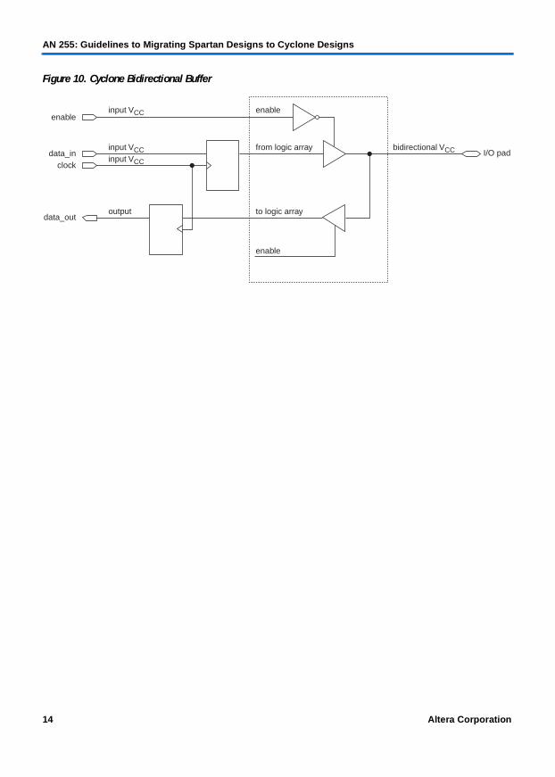
Figure 21 shows an example of the RAMB4_S1_S1 primitive.
Table 11. RAMB4_Sm_Sn Configuration
Component Port A Depth (Bits)
Port A Address
Port A Data Input Width
(Bits)
Port B Depth (Bits)
Port B Address
Port B Data Input Width
(Bits)
RAMB4_S1_S1 4,096 12 1 4,096 12 1
RAMB4_S1_S2 4,096 12 1 2,048 11 2
RAMB4_S1_S4 4,096 12 1 1,024 10 4
RAMB4_S1_S8 4,096 12 1 512 9 8
RAMB4_S1_S16 4,096 12 1 256 8 16
RAMB4_S2_S2 2,048 11 2 2,048 11 2
RAMB4_S2_S4 2,048 11 2 1,024 10 4
RAMB4_S2_S8 2,048 11 2 512 9 8
RAMB4_S2_S16 2,048 11 2 256 8 16
RAMB4_S4_S4 1,024 10 4 1,024 10 4
RAMB4_S4_S8 1,024 10 4 512 9 8
RAMB4_S4_S16 1,024 10 4 256 8 16
RAMB4_S8_S8 512 9 8 512 9 8
RAMB4_S8_S16 512 9 8 256 8 16
RAMB4_S16_S16 256 8 16 256 8 16
28 Altera Corporation
AN 255: Guidelines to Migrating Spartan Designs to Cyclone Designs
Figure 21. RAMB4_S1_S1 Primitive
The Cyclone device altsyncram megafunction provides the equivalent to the Spartan-IIE RAMB4_Sm_Sn primitive. Set the following options for the altsyncram megafunction in the MegaWizard Plug-in Manager to provide an equivalent for the RAMB4_Sm_Sn primitive in a Cyclone device.
■ Enable “With two Read/write ports (True dual-port RAM).”■ Enable “Use different data widths on different ports” if data widths
vary.■ Enable “Customize clocks for A and B ports.”■ Specify a 4-Kbit memory size.■ Set the output width to match the output width of the primitive.
1 If your design requires either a wider or deeper RAM block, specify the exact width and depth of the RAM block in the MegaWizard Plug-In Manager.
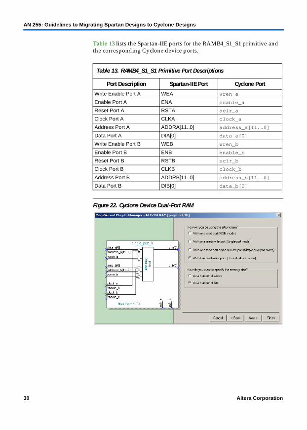
When implementing dual-port RAM in a Cyclone device, Table 12 shows the modes available when a read occurs during a write.
ENASSRA
CLKA
WEA SP0
DOB[0]
DIA
ADDRA[11..0]WEBENB
SSRB
CLKBDIB[0]
ADDRB[11..0]
RAMB4_S1_S1
Table 12. Behavior of Read-During-Write
Mode M4K Block
Same-port read-during-write New data available at positive clock edge
Mixed-port read-during-write Outputs set to unknown or old data
Altera Corporation 29
AN 255: Guidelines to Migrating Spartan Designs to Cyclone Designs
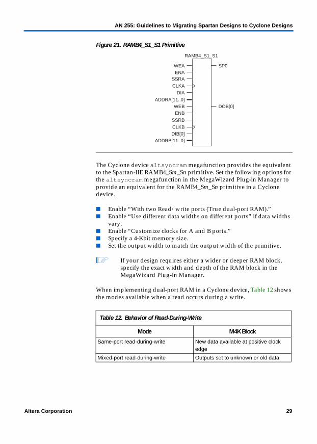
Table 13 lists the Spartan-IIE ports for the RAMB4_S1_S1 primitive and the corresponding Cyclone device ports.
Figure 22. Cyclone Device Dual-Port RAM
Table 13. RAMB4_S1_S1 Primitive Port Descriptions
Port Description Spartan-IIE Port Cyclone Port
Write Enable Port A WEA wren_a
Enable Port A ENA enable_a
Reset Port A RSTA aclr_a
Clock Port A CLKA clock_a
Address Port A ADDRA[11..0] address_a[11..0]
Data Port A DIA[0] data_a[0]
Write Enable Port B WEB wren_b
Enable Port B ENB enable_b
Reset Port B RSTB aclr_b
Clock Port B CLKB clock_b
Address Port B ADDRB[11..0] address_b[11..0]
Data Port B DIB[0] data_b[0]
30 Altera Corporation

AN 255: Guidelines to Migrating Spartan Designs to Cyclone Designs
16-Bit Shift Register Look-up-Table
The SRL16 primitive implements a 16-bit look-up table (LUT) shift register. Data shifting is synchronized with the clock except when address lines are changed, and the output bit position is dynamically selectable. Address lines A3 – A0 can dynamically adjust the length of the shift register. Figure 23 shows the schematic for SRL16.
Figure 23. SRL16 Primitive
You can use either the lpm_shiftreg or altshift_taps megafunction to replace the Spartan-IIE SRL16 primitive, depending on the resources available on the Cyclone device. Cyclone devices implement the lpm_shiftreg megafunction in LEs and the altshift_taps megafunction in M4K RAM blocks. Both megafunctions provide dynamic shifting by reading the data at any of the bit positions in the shift register's data path. You must enable the data output port in the lpm_shiftreg. The altshift_taps megafunction automatically implements dynamic shifting. However, you must specify the number of taps and the tap distance.
Figures 24 and 25 show the lpm_shiftreg and altshift_taps megafunctions, as set-up in the MegaWizard Plug-in Manager.
DC
Q
A0
A1A2A3
SRL16
Altera Corporation 31

AN 255: Guidelines to Migrating Spartan Designs to Cyclone Designs
32 Altera Corporation
Figure 24. lpm_shiftreg Megafunction
Figure 25. altshift_taps Megafunction
Table 14 lists the Spartan-IIE ports for the SRL16 primitive and the corresponding lpm_shiftreg and altshift_taps megafunction ports.

AN 255: Guidelines to Migrating Spartan Designs to Cyclone Designs
Note to Table 14:(1) The lpm_shiftreg and altshift_taps megafunctions can provide dynamic shifting by feeding the outputs q
and taps, from their respective megafunction, into a 16-to-1 multiplexer, and have the control line of the multiplexer controlled by the SRL16 address line.
Table 15 shows variations to the Spartan-IIE SRL16 primitive.
Both the lpm_shiftreg and altshift_taps megafunctions can provide the optional clock enable port to create the equivalent functionality to the variants of the SRL16 primitive.
Converting CORE Generator System Modules
Designers can use the Xilinx CORE Generator System tool, which is similar to Altera’s MegaWizard Plug-In Manager, to create Spartan-IIE functions.
The CORE Generator System tool provides a list of customizable functions, ranging from digital signal processing to mathematical functions. A designer can select a function from the list and, after customizing the module, the CORE Generator System tool will create a netlist file containing the required functionality.
Identifying CORE Generator System functions is different from identifying primitives because the function names do not follow a standard convention. You can use a third-party synthesis tool to help in the identification process. After the tool synthesizes the design, it records a list of identified modules in the log file.
Table 14. lpm_shiftreg & altshift_taps Megafunction Port Descriptions
Port Description Spartan-IIE Port Cyclone Port(lpm_shiftreg)
Cyclone Port(altshift_taps)
Shift Register Input D shiftin shiftin
Clock CLK clock clock
Shift Register Output Q shiftout shiftout
Select Bit Position A[3..0] q[15..0] (1) taps[15..0] (1)
Table 15. SRL16 Variations
Xilinx Primitive Name Description
SRL16_1 Negative-edge-triggered 16-bit shift register
SRL16E 16-bit shift register with clock enable
SRL16E_1 Negative-edge-triggered 16-bit shift register with clock enable
Altera Corporation 33

AN 255: Guidelines to Migrating Spartan Designs to Cyclone Designs
This section provides the steps necessary to convert CORE Generator System modules into Cyclone megafunctions using the Altera MegaWizard Plug-In Manager. This section describes the following functions:
■ Creating dual-port memory■ Creating FIFO buffers■ Creating multipliers
Creating Dual-Port Memory
Spartan-IIE Block SelectRAM memory provides true dual-port RAM functionality. This feature allows you to simultaneously read from and write to RAM from independent read and write ports. The dual-port Block SelectRAM memory, shown in Figure 26, is fully synchronous; all operations are performed with respect to either the rising or falling edge of the clock signal. Two independent clocks, CLKA and CLKB, clock the memory, and each clock controls its respective port. Optionally, enable pins ENA and ENB can also control the ports.
Spartan-IIE devices provide both Block SelectRAM memory and distributed SelectRAM memory. Block SelectRAM memory is implemented in dedicated 4-Kbit memory blocks, which provide fully synchronous memory structures.
34 Altera Corporation

AN 255: Guidelines to Migrating Spartan Designs to Cyclone Designs
Figure 26. Dual-Port Block SelectRAM Memory
The following guidelines apply to the three write modes supported by dual-port Block SelectRAM memory.
■ It is a fully synchronous memory.■ Simultaneous reads from the same memory location may occur, but
all other simultaneous read and write operations from the same memory location will result in correct data being written into the memory but invalid data being read.
■ ENA and ENB enable the read, write, and SINIT functionality of their respective ports.
■ When the SINITA and SINITB ports are asserted, they place a user-defined value on the outputs.
Cyclone devices can implement true dual-port memory in M4K RAM blocks, providing equivalent functionality to Spartan-IIE dual-port memory. To implement Spartan-IIE dual-port memory functionality in a Cyclone device, use the altsyncram megafunction, shown in Figure 27.
f For more information on implementing dual-port memory in Cyclone devices, see AN 252: On-Chip Memory Implementations Using Cyclone Memory Blocks.
ADDRA
DINA
ENA
WEA
CLKA
NDA
SINITA
ADDRB
DINB
ENB
WEB
CLKB
NDB
SINITB
DOUTA
RFDA
RDYA
DOUTB
RFDB
RDYB
Altera Corporation 35

AN 255: Guidelines to Migrating Spartan Designs to Cyclone Designs
Figure 27. altsyncram Megafunction
data_a[7..0]
address_a[4..0]
wren_a
data_b[7..0]
address_b[4..0]
wren_b
clock
altsyncram
q_a[7..0]
q_b[7..0]
32-WordRAM
36 Altera Corporation

AN 255: Guidelines to Migrating Spartan Designs to Cyclone Designs
Altera Corporation 37
Set the following options for the altsyncram megafunction in the MegaWizard Plug-in Manager to implement true dual-port memory in Cyclone devices.
■ Enable the “With two read/write ports (true dual-port mode)” memory structure.
■ You can use either Single clock or Customize clocks for A and B ports, depending on the clocking scheme used in Spartan-IIE dual-port memory.
■ The clock enable pin is optional.■ You can use an optional asynchronous clear to clear the output of the
dual-port memory.■ You can set the Mixed Port Read-During-Write for Single Input Clock
RAM to be either “Old memory contents appear” or “I don’t care”
Table 16 lists the Spartan-IIE ports and the corresponding Cyclone device ports for dual-port RAM.
Table 16. Port Comparison between Xilinx’s & Altera’s Dual-Port RAM
Dual-Port Block Memory altsyncram Comments
ADDRA [n:0] address_a[n..0]
DINA [m:0] data_a[m:0]
WEA wren_a
ENA enable_a
SINITA aclr Asynchronously clear the output port
NDA Not Available Hand-shaking signal
CLKA clock_a
ADDRB [n:0] address_b[n..0]
DINB [m:0] data_b[m..0]
WEB wren_b
ENB enable_b
SINITB aclr Asynchronously clear the output port
NDB Not Available Hand-shaking signal
CLKB clock_b
DOUTA q_a[n..0]
RFDA Not Available Hand-shaking signal
RDYA Not Available Hand-shaking signal
DOUTB q_b[n..0]
RFDB Not Available Hand-shaking signal
RDYB Not Available Hand-shaking signal

AN 255: Guidelines to Migrating Spartan Designs to Cyclone Designs
38 Altera Corporation
Creating FIFO Buffers
Asynchronous FIFO buffers implement first-in-first-out logic with both a read and write clock. The asynchronous part of the name is based on the existence of independent read and write clocks for the FIFO buffer.
Figure 28. Asynchronous FIFO
Cyclone devices implement FIFO buffers similar to previous device families such as APEXTM 20KE and APEX II devices. The lpm_fifo+ megafunction does not support the following asynchronous handshaking signals:
■ WR_ACK■ WR_ERR■ RD_ACK■ RD_ERR
DIN
WR_EN
WR_CLK
WR_ERR
WR_COUNT
DOUT
RD_CLK
RD_EN
FULL
ALMOST_FULL
WR_ACK
EMPTY
ALMOST EMPTY
RD_ACK
RD_ERR
RD_COUNT
AINIT

AN 255: Guidelines to Migrating Spartan Designs to Cyclone Designs
Table 17 lists the Spartan-IIE ports and the corresponding Cyclone device ports for an asynchronous FIFO buffer.
The issue of metastability is inherent in the creation of any FIFO buffer. Therefore, a one-to-one mapping is not sufficient to carry the conversion process of the asynchronous FIFO buffer with an lpm_fifo megafunction. You must perform timing simulations to verify functionality. Figure 29 shows the lpm_fifo megafunction.
Table 17. Port Comparison Between the Xilinx & Altera FIFO
Spartan-IIE Asynchronous FIFO
Altera lpm_fifo Comments
DIN[N:0] data[N..0]
WR_EN wrreq
WR_CLK wrclk
RD_EN rdreq
RD_CLK rdclk
AINIT Not Available
FULL wrfull Indicates no additional writes can be performed
ALMOST_FULL Not Available Indicates one additional write can be performed
WR_COUNT[W:0} wrusedw[] Write count vector
WR_ACK Not Available Hand-shaking signal
WR_ERR Not Available Hand-shaking signal
DOUT[N:0] q[N..0]
EMPTY rdemtpy Indicates no additional read is possible
ALMOST_EMPTY Not Available
RD_COUNT[R:0] rdusedw Read count vector
RD_ACK Not Available Hand-shaking signal
RD_ERR Not Available Hand-shaking signal
Altera Corporation 39

AN 255: Guidelines to Migrating Spartan Designs to Cyclone Designs
40 Altera Corporation
Figure 29. lpm_fifo Megafunction
Creating Multipliers
Cyclone devices offer modes equivalent to Spartan-IIE’s Parallel and Constant Coefficient mode. However, no direct conversion exists for the sequential multiplier mode.
The Spartan-IIE Parallel Multiplication mode is equivalent to either the default implementation or ESBs implementation modes available in the Cyclone device. Each mode allows the A and B inputs to be either both signed, both unsigned, or one signed and the other unsigned. If either input A or B is signed, the result is signed.
Unlike the Spartan CORE Generator System multipliers, the lpm_mult and altmult_add megafunctions do not provide hand-shaking ability (e.g., ND, RFD, and RDY signals). See Figure 30.
data[7..0]
wrfull
q[7..0]
rdreq
rdclock rdempty
data[7..0]
data[7..0]
8 bits × 256 words
lpm_fifo

AN 255: Guidelines to Migrating Spartan Designs to Cyclone Designs
Figure 30. Spartan CORE Generator System Multiplier
CORE Generator System functions have three types of multiplier modes.
■ Parallel Multiplier: This mode multiplies A and B, either in LUTs or in discrete multiplier blocks.
■ Constant Coefficient Multiplier: This mode allows you to multiply one input (A) by a constant value. This value can be either static or dynamic.
■ Sequential Multiplier: This mode breaks down a large multiplier into a series of smaller multipliers, where the result is taken from the summation of the smaller multipliers. This results in a smaller multiplier but incurs latency.
You can use the lpm_mult or altmult_add megafunction for Cyclone designs to replace Spartan-IIE’s Multiplier function. Depending on the features used in the Spartan-IIE’ s Multiplier design, you should use either the lpm_mult or altmult_add megafunction.
1 Make sure to identify latency in the multiplier.
Figure 31 shows the lpm_mult megafunction.
A
LOADB
SWAPB
RFD
RDY
O
Q
LOAD_DONE
A_SIGNED
B
CLK
ND
CE
SCLRACLR
Altera Corporation 41

AN 255: Guidelines to Migrating Spartan Designs to Cyclone Designs
42 Altera Corporation
Figure 31. lpm_mult Megafunction
Use the following guidelines with the lpm_mult megafunction when replacing the Spartan-IIE multiplier function. If your design does not meet any of these three requirements, you can use the altmult_add megafunction to replace the Spartan-IIE multiplier function.
■ The Port B value can be a constant.■ The sign of port A must not change.■ Both input ports must be of the same sign, either signed or unsigned.
The required options for the lpm_mult megafunction to operate similarly to the Spartan-IIE Multiplier function are:
■ Disable the sum input port.■ Specify the sign of the multiplier.■ Enable pipelining of this function and specify the latency of the
multiplier. ■ Specify a pipeline of 2 to register both inputs and outputs. Specify a
pipeline of 1 to register only inputs.
altmult_add Megafunction
You can also use the altmult_add megafunction, shown in Figure 32, to replace the Spartan-IIE multiplier function if your design does not meet the requirements for the lpm_mult megafunction. You can register inputs and outputs with the altmult_add megafunction, the sign of port A can by dynamic, and the sign of the input ports can be different. However, you cannot use the altmult_add megafunction to dynamically load a new constant value into the multiplier.
dataa[7..0]
datab[7..0]
lpm_mult
result[15..0]
Unsignedmultiplication

AN 255: Guidelines to Migrating Spartan Designs to Cyclone Designs
Figure 32. altmult_add Megafunction
Note to Figure 32:(1) Both the dataa_0 and datab_0 lines are unsigned.
Use the following settings in the MegaWizard Plug-In Manager when customizing an altmult_add megafunction to perform similarly to the Spartan-IIE multiplier function.
■ Enable the use of only one multiplier.■ Specify the sign of ports A and B to be either signed, unsigned, or (for
port A) variable.■ Enable the registering of the inputs and outputs.
Migrate Spartan-IIE Design Constraints into the Quartus II Software
When designing for a Spartan-IIE device, the User Constraint File (.ucf) contains the constraints and attributes for the design. This file is similar to the Quartus II software’s Compiler Settings Files (.csf or .esf) and Project Settings Files (.psf). The UCF file contains all of the design’s constraints and attributes, from timing requirements to location assignments.
Since the Xilinx tool does not report unconstrained paths, the user must provide constraints for two purposes: to constrain the net (or instance), and to report the constraint. The Quartus II Timing Analyzer analyzes and reports on all paths in a design, therefore, constraints provided merely to report a constraint are not required. Therefore, many constraints placed by the user in the Xilinx tool are not necessary after converting your design to the Cyclone architecture in Altera’s Quartus II design environment.
dataa_0[15..0]
datab_0[15..0]
clock
altmult_add
result[15..0]
CD
CD
CD CD
MULT0
Altera Corporation 43

AN 255: Guidelines to Migrating Spartan Designs to Cyclone Designs
Timing Constraints
The timing constraints specify to the Quartus II software what requirements are necessary for the design to function correctly. These constraints may include system performance, I/O timing requirements, or point-to-point timing requirements.
The Quartus II Assignment Organizer allows you to view, add, and create assignments to nodes and entities, such as location assignments, timing assignments, options for individual nodes only, options for individual nodes and entities, options for entities only, parameter, and simulation assignments.
1 You can open the Assignment Organizer dialog box for a specific node or entity from the Node Finder dialog box, from the Project Navigator, or from the Floorplan Editor.
The Assignment Organizer dialog box has two tabs, the By Node tab and the By Category tab.
■ Use the By Node tab to edit project defaults, Compiler settings, and specific entity and node settings
■ Use the By Category tab to view and edit assignments according to their category.
44 Altera Corporation

AN 255: Guidelines to Migrating Spartan Designs to Cyclone Designs
Figure 33. The Quartus II Assignment Organizer
Altera Corporation 45
AN 255: Guidelines to Migrating Spartan Designs to Cyclone Designs
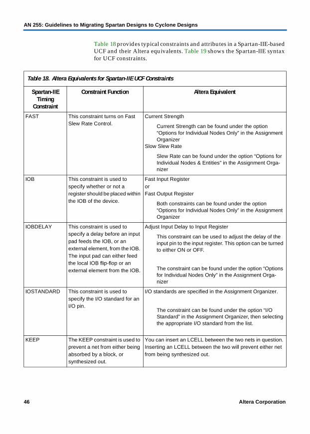
Table 18 provides typical constraints and attributes in a Spartan-IIE-based UCF and their Altera equivalents. Table 19 shows the Spartan-IIE syntax for UCF constraints.
Table 18. Altera Equivalents for Spartan-IIE UCF Constraints
Spartan-IIE Timing
Constraint
Constraint Function Altera Equivalent
FAST This constraint turns on Fast Slew Rate Control.
Current Strength
Current Strength can be found under the option “Options for Individual Nodes Only” in the Assignment Organizer
Slow Slew Rate
Slew Rate can be found under the option “Options for Individual Nodes & Entities” in the Assignment Orga-nizer
IOB This constraint is used to specify whether or not a register should be placed within the IOB of the device.
Fast Input Register orFast Output Register
Both constraints can be found under the option “Options for Individual Nodes Only” in the Assignment Organizer
IOBDELAY This constraint is used to specify a delay before an input pad feeds the IOB, or an external element, from the IOB. The input pad can either feed the local IOB flip-flop or an external element from the IOB.
Adjust Input Delay to Input Register
This constraint can be used to adjust the delay of the input pin to the input register. This option can be turned to either ON or OFF.
The constraint can be found under the option “Options for Individual Nodes Only” in the Assignment Orga-nizer
IOSTANDARD This constraint is used to specify the I/O standard for an I/O pin.
I/O standards are specified in the Assignment Organizer.
The constraint can be found under the option “I/O Standard” in the Assignment Organizer, then selecting the appropriate I/O standard from the list.
KEEP The KEEP constraint is used to prevent a net from either being absorbed by a block, or synthesized out.
You can insert an LCELL between the two nets in question. Inserting an LCELL between the two will prevent either net from being synthesized out.
46 Altera Corporation

AN 255: Guidelines to Migrating Spartan Designs to Cyclone Designs
Altera Corporation 47
MAXDELAY This constraint is used to specify the maximum delay in a net.
MAXDELAY has no direct conversion constraint for the Quartus II software. However, if the net exists between two registers, an fMAX constraint can be used. If the net is purely combinatorial, a tPD assignment can be made.
Setting a tPD assignment can be made under section “Timing” in the Assignment Organizer.
MAXSKEW This constraint is used to specify the maximum skew in a net.
MAXSKEW has no direct conversion constraint for the Quartus II software. However, if the net exists between two registers, an fMAX constraint can be used. If the net is purely combinatorial, a tPD assignment can be made.
Setting a tPD assignment can be made under section “Timing” in the Assignment Organizer.
NODELAY This constraint is used to reduce setup time at the cost of positive hold time.
Specify a Setup time parameter option, tSU, that is available in the Assignment Organizer.
Setting a tSU assignment can be made under section “Timing” in the Assignment Organizer.
OFFSET(Continued in next row)
This constraint specifies the correlation between a global clock and its associated data in, or data out, pin. This is used to specify setup and Clock to Out constraints on the data registers.
The Assignment Organizer can be used to specify the tCO constraint in the Quartus II software.
Setting a tCO assignment can be made under the sec-
tion “Timing” in the Assignment Organizer.
OFFSET (cont.) This constraint specifies the correlation between a global clock and its associated data in, or data out, pin. This is used to specify setup and Clock to Out constraints on the data registers.
The Assignment Organizer can be used to specify the tSU constraint in the Quartus II software.
Setting a tSU assignment can be made under the sec-tion “Timing” in the Assignment Organizer.
PERIOD This constraint specifies the timing relationship of a global clock such as an fMAX requirement.
fMAX timing requirements can be specified in the Timing Settings dialog box.
The Timing Settings dialog box can be found under the Project menu.
Individual clock settings can be made for independent clocks.Also, a global setting can be made, which applies to all clocks.
Table 18. Altera Equivalents for Spartan-IIE UCF Constraints
Spartan-IIE Timing
Constraint
Constraint Function Altera Equivalent

AN 255: Guidelines to Migrating Spartan Designs to Cyclone Designs
Table 19. Spartan-IIE UCF Constraint Syntax
Spartan-IIE Timing Constraint
UCF Syntax
FAST INST inst_name FAST
NET net_name FAST
IOB INST inst_name IO = {TRUE | FALSE}
IOBDELAY INST inst_name IOBDELAY = { NONE | BOTH | IBUF | IFD}
IOSTANDARD INST <pad name> IOSTANDARD = io_standard, where io_standard is the name of the I/O standard as listed in the “Selectable I/O Interfaces” section.
KEEP NET <net name> KEEP
MAXDELAY NET <net name> MAXDELAY = number (units), where number is any whole number, and units = ps, ns, µs, ms, GHz, MHz, or kHz.
MAXSKEW NET <net name> MAXSKEW = number (units), where number is any whole number and units = ps, ns, µs, ms, GHz, MHz, or kHz.
NODELAY INST $inst_name/reg_name NODELAYor NET net_name NODELAY
OFFSET(Continued in next row.)
Clock to Out (tCO)A tCO timing parameter is specified with the following syntax:
NET <net_name> OFFSET = IN : 10 : AFTER : clk_name;
The above indicates that <net_name> should have a tCO of 10 ns with respect to clock clk_name. The default unit is nanoseconds.(Continued in next row.)
OFFSET (cont.) Set up Time (tSU)A setup timing parameter is specified with the following syntax:
NET <net name> OFFSET = OUT : 10 : BEFORE : clk_name;
The above indicates that <net name> should have a tSU of 10 ns with respect to clock clk_name. The default unit is nanoseconds.
PERIOD NET <clock name> PERIOD = 50;
The above indicates that clock <clock name> should have a period of 50 ns or 20 MHz. The default unit is nanoseconds.
48 Altera Corporation

AN 255: Guidelines to Migrating Spartan Designs to Cyclone Designs
Placement Constraint
Spartan-IIE-based placement constraints do not carry over to Cyclone placement constraints. Do not make placement constraints to a design until the conversion process involving the Quartus II software is complete.
Spartan-IIE-based placement constraints include the following:
■ LOC■ RLOC■ RLOC_ORIGIN■ RLOC_RANGE■ MAP
Compile in the Quartus II Software
Once you have completely migrated the Spartan-IIE design to a Cyclone design, you must compile the design in the Quartus II software. Compiling the design in the Quartus II software will generate detailed timing analysis results from the design along with programming files for the targeted Cyclone device.
f For more information on compiling designs in the Quartus II software see the Quartus II Tutorial located within the Quartus II software. Select Tutorial from the Help menu.
Verify the Conversion
Verify the conversion to ensure that the design can run in a Cyclone device. You can either perform a functional verification or a timing verification on the converted design elements or the entire design. The Quartus II software creates the necessary simulation information files to run both functional and timing simulations in third-party simulators such as ModelSim.
f For more information on ModelSim and the Quartus II software flow, see AN 204: Using ModelSim-Altera in a Quartus II Design Flow.
Conclusion You can migrate your Spartan-IIE design to a Cyclone design using the Quartus II software and the MegaWizard Plug-In. This application note provides guidelines to the migration process, allowing you to take advantage of the cost-sensitive Cyclone architecture.
Altera Corporation 49

AN 255: Guidelines to Migrating Spartan Designs to Cyclone Designs
References For more information, refer to the following documents:
■ Cyclone FPGA Family Data Sheet■ AN 210: Converting Memory from Asynchronous to Synchronous for
Stratix Devices■ AN 225: LeonardoSpectrum & Quartus II Design Methodology■ AN 226: Synplify & Quartus II Design Methodology■ Quartus II Software Quick Start Guide For Quartus II Software Version 2.1
Manual■ altpll Megafunction User Guide■ Xilinx Libraries Guide, available at www.xilinx.com
50 Altera Corporation
101 Innovation DriveSan Jose, CA 95134(408) 544-7000http://www.altera.comApplications Hotline:(800) 800-EPLDLiterature Services:[email protected]
Copyright © 2002 Altera Corporation. All rights reserved. Altera, The Programmable Solutions Company, thestylized Altera logo, specific device designations, and all other words and logos that are identified astrademarks and/or service marks are, unless noted otherwise, the trademarks and service marks of AlteraCorporation in the U.S. and other countries. All other product or service names are the property of theirrespective holders. Altera products are protected under numerous U.S. and foreign patents and pendingapplications, maskwork rights, and copyrights. Altera warrants performance of its semiconductor products tocurrent specifications in accordance with Altera's standard warranty, but reserves the rightto make changes to any products and services at any time without notice. Altera assumesno responsibility or liability arising out of the application or use of any information,product, or service described herein except as expressly agreed to in writing by AlteraCorporation. Altera customers are advised to obtain the latest version of devicespecifications before relying on any published information and before placing orders forproducts or services.