Embed Size (px)
Citation preview
Future Technology Devices International Limited
Unit 1, 2 Seaward Place, Centurion Business Park, Glasgow G41 1HH United Kingdom Tel.: +44 (0) 141 429 2777 Fax: + 44 (0) 141 429 2758
E-Mail (Support): [email protected] Web: http://www.ftdichip.com
Copyright © 2008 Future Technology Devices International Limited
Future Technology Devices International Ltd.
Application Note AN_106
Interfacing to a USB Printer using Vinculum
VNC1L Host Controller
Document Reference No.: FT_000064
Version 1.0
Issue Date: 2008-11-24
This application note describes how to add printing capability to an embedded design via a USB
interface using FTDI’s Vinculum Host controller VNC1L. VNC1L implements USB Printer Class and
gives a command monitor port interface for controlling USB printers using standard PCL ASCII
commands. Details of how a battery operated portable printer HP-DeskJet 460 printer was
interfaced with Freescale’s 16-bit micro-controller HC12 using VNC1L on SPI monitor port are
presented.
This design can be applied to a variety of real-life embedded applications including medical
portable devices, field tester devices, logistics, point of sales, rentals, queuing systems, ticketing
system, gas receipts, etc. that require a printer interface. We highlight a product in the market
Quantifit from OHD that uses VNC1L to provide USB printer capability to a field fitness testing
device using the design in this application note.
Copyright © 2008 Future Technology Devices International Limited 1
Document Reference No.: FT_000064 Using Vinculum USB Host Controller Printer Interface Application Note AN_106
Version 1.0 Clearance No.: FTDI# 68
Table of Contents
1 Introduction............................................................................................ 2
2 Project framework ................................................................................. 3
2.1 Project Installation .............................................................................................. 3
2.2 Project Structure ................................................................................................. 3
3 Software Theory and Command Structure .......................................... 4
3.1 Block Diagram: VNC1L Printer Interface Design .............................................. 4
3.2 USB Printer Class Details ................................................................................... 4
3.3 VNC1L Printer Interface Commands .................................................................. 5
3.4 Printer PCL Commands ...................................................................................... 7
3.5 HC12 Firmware Details ........................................................................................ 8
3.5.1 Theory of Operation ................................................................................................................. 8
3.5.2 Firmware Routines................................................................................................................... 9
4 Hardware Connections and Running the Demo ................................ 10
4.1 Jumper Settings ................................................................................................ 10
4.2 LED Usage.......................................................................................................... 12
4.3 Printer Output .................................................................................................... 12
5 Summary .............................................................................................. 13
6 Contact Information............................................................................. 14
Appendix A – Acknowledgements ........................................................... 15
Appendix B - References .......................................................................... 16
Appendix C – HC12 Firmware Source Code ............................................ 17
Appendix D – Revision History ................................................................. 25
Copyright © 2008 Future Technology Devices International Limited 2
Document Reference No.: FT_000064 Using Vinculum USB Host Controller Printer Interface Application Note AN_106
Version 1.0 Clearance No.: FTDI# 68
1 Introduction
In the printer marketplace, USB is the defacto interconnect standard for personal printers. The Universal
Serial Bus (USB) has several advantages over previous generation of connection methods such as parallel
ports. A USB port is much faster than a parallel port (can handle 12Mbps) and a single port can handle
different devices e.g. a USB port can handle USB Flash disks, mouse and keyboard whereas the parallel
port was dedicated for the printer connection. The USB enumeration process that occurs when a device is
connected to the USB host handles the device requirements using standard USB descriptors supplied by
the device. This is completely transparent to user. Users just plug in the printer and see it is ready for
use.
USB 2.0 specification defines a specific device class for printing devices. VNC1L USB Host controller
implements and supports USB print class device, configuration, and interface and endpoint descriptors as
per USB printer device specification. It also supports USB printer class specific request and response
structure used by basic Printer Command language (PCL) interface. Note: The VNC1L Host does not
provide drivers for printers.
Most modern printers support built-in fonts and as such they can print text, using basic printer control
codes, directly from the Vinculum Monitor. Other printers will require embedded fonts or graphics to be
sent as part of a print job. Most modern printers support a PCL language as the protocol for an operating
system driver to communicate with the printer. If the printer supports PCL language it can be controlled
by the VNC1L using the methods outlined in this application note.
Copyright © 2008 Future Technology Devices International Limited 3
Document Reference No.: FT_000064 Using Vinculum USB Host Controller Printer Interface Application Note AN_106
Version 1.0 Clearance No.: FTDI# 68
2 Project framework
2.1 Project Installation
The VPD.msi is the installation file for the project. When this file is run, the installer will install the project
files into C:\Program Files\Vinculum Printer Demo folder (the installer will give an option for selecting the
target folder). After successful installation the target folder is created and all source code files will be
present as per the file structure shown in Figure 1 below.
2.2 Project Structure
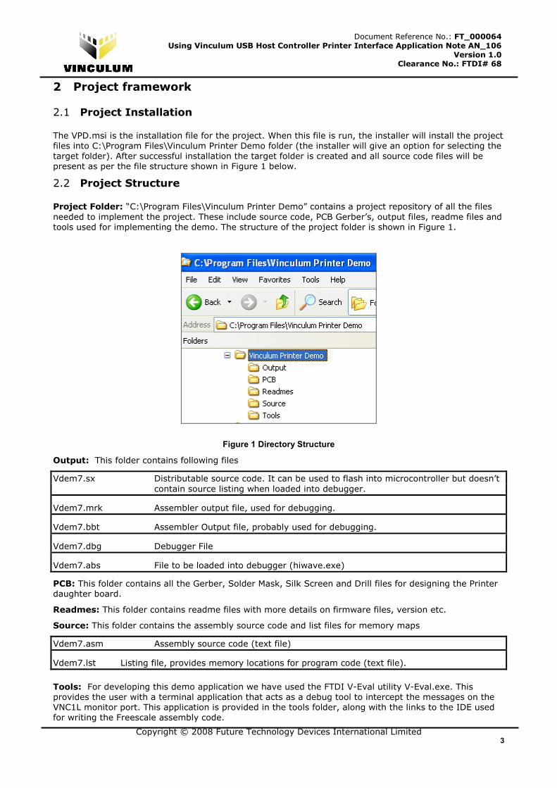
Project Folder: “C:\Program Files\Vinculum Printer Demo” contains a project repository of all the files
needed to implement the project. These include source code, PCB Gerber’s, output files, readme files and
tools used for implementing the demo. The structure of the project folder is shown in Figure 1.
Figure 1 Directory Structure
Output: This folder contains following files
Vdem7.sx Distributable source code. It can be used to flash into microcontroller but doesn’t
contain source listing when loaded into debugger.
Vdem7.mrk Assembler output file, used for debugging.
Vdem7.bbt Assembler Output file, probably used for debugging.
Vdem7.dbg Debugger File
Vdem7.abs File to be loaded into debugger (hiwave.exe)
PCB: This folder contains all the Gerber, Solder Mask, Silk Screen and Drill files for designing the Printer
daughter board.
Readmes: This folder contains readme files with more details on firmware files, version etc.
Source: This folder contains the assembly source code and list files for memory maps
Vdem7.asm Assembly source code (text file)
Vdem7.lst Listing file, provides memory locations for program code (text file).
Tools: For developing this demo application we have used the FTDI V-Eval utility V-Eval.exe. This
provides the user with a terminal application that acts as a debug tool to intercept the messages on the
VNC1L monitor port. This application is provided in the tools folder, along with the links to the IDE used
for writing the Freescale assembly code.
Copyright © 2008 Future Technology Devices International Limited 4
Document Reference No.: FT_000064 Using Vinculum USB Host Controller Printer Interface Application Note AN_106
Version 1.0 Clearance No.: FTDI# 68
3 Software Theory and Command Structure
3.1 Block Diagram: VNC1L Printer Interface Design
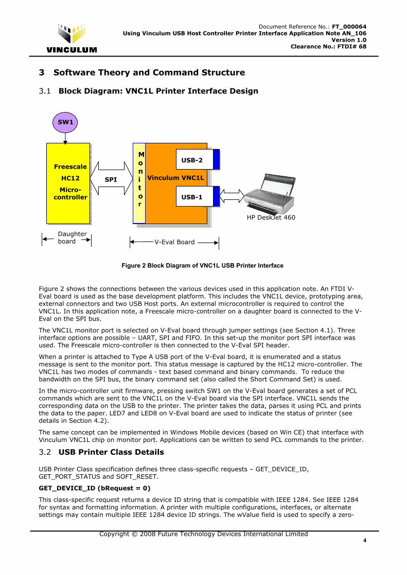
Figure 2 Block Diagram of VNC1L USB Printer Interface
Figure 2 shows the connections between the various devices used in this application note. An FTDI V-
Eval board is used as the base development platform. This includes the VNC1L device, prototyping area,
external connectors and two USB Host ports. An external microcontroller is required to control the
VNC1L. In this application note, a Freescale micro-controller on a daughter board is connected to the V-
Eval on the SPI bus.
The VNC1L monitor port is selected on V-Eval board through jumper settings (see Section 4.1). Three
interface options are possible – UART, SPI and FIFO. In this set-up the monitor port SPI interface was
used. The Freescale micro-controller is then connected to the V-Eval SPI header.
When a printer is attached to Type A USB port of the V-Eval board, it is enumerated and a status
message is sent to the monitor port. This status message is captured by the HC12 micro-controller. The
VNC1L has two modes of commands - text based command and binary commands. To reduce the
bandwidth on the SPI bus, the binary command set (also called the Short Command Set) is used.
In the micro-controller unit firmware, pressing switch SW1 on the V-Eval board generates a set of PCL
commands which are sent to the VNC1L on the V-Eval board via the SPI interface. VNC1L sends the
corresponding data on the USB to the printer. The printer takes the data, parses it using PCL and prints
the data to the paper. LED7 and LED8 on V-Eval board are used to indicate the status of printer (see
details in Section 4.2).
The same concept can be implemented in Windows Mobile devices (based on Win CE) that interface with
Vinculum VNC1L chip on monitor port. Applications can be written to send PCL commands to the printer.
3.2 USB Printer Class Details
USB Printer Class specification defines three class-specific requests – GET_DEVICE_ID,
GET_PORT_STATUS and SOFT_RESET.
GET_DEVICE_ID (bRequest = 0)
This class-specific request returns a device ID string that is compatible with IEEE 1284. See IEEE 1284
for syntax and formatting information. A printer with multiple configurations, interfaces, or alternate
settings may contain multiple IEEE 1284 device ID strings. The wValue field is used to specify a zero-
Daughter board
USB-2
USB-1
Freescale
HC12
Micro-controller
Vinculum VNC1L
HP DeskJet 460
SPI
M
o
n
i
t
or
SW1
V-Eval Board
Copyright © 2008 Future Technology Devices International Limited 5
Document Reference No.: FT_000064 Using Vinculum USB Host Controller Printer Interface Application Note AN_106
Version 1.0 Clearance No.: FTDI# 68
based configuration index. The high-byte of the wIndex field is used to specify the zero-based interface
index. The low-byte of the wIndex field is used to specify the zero-based alternate setting.
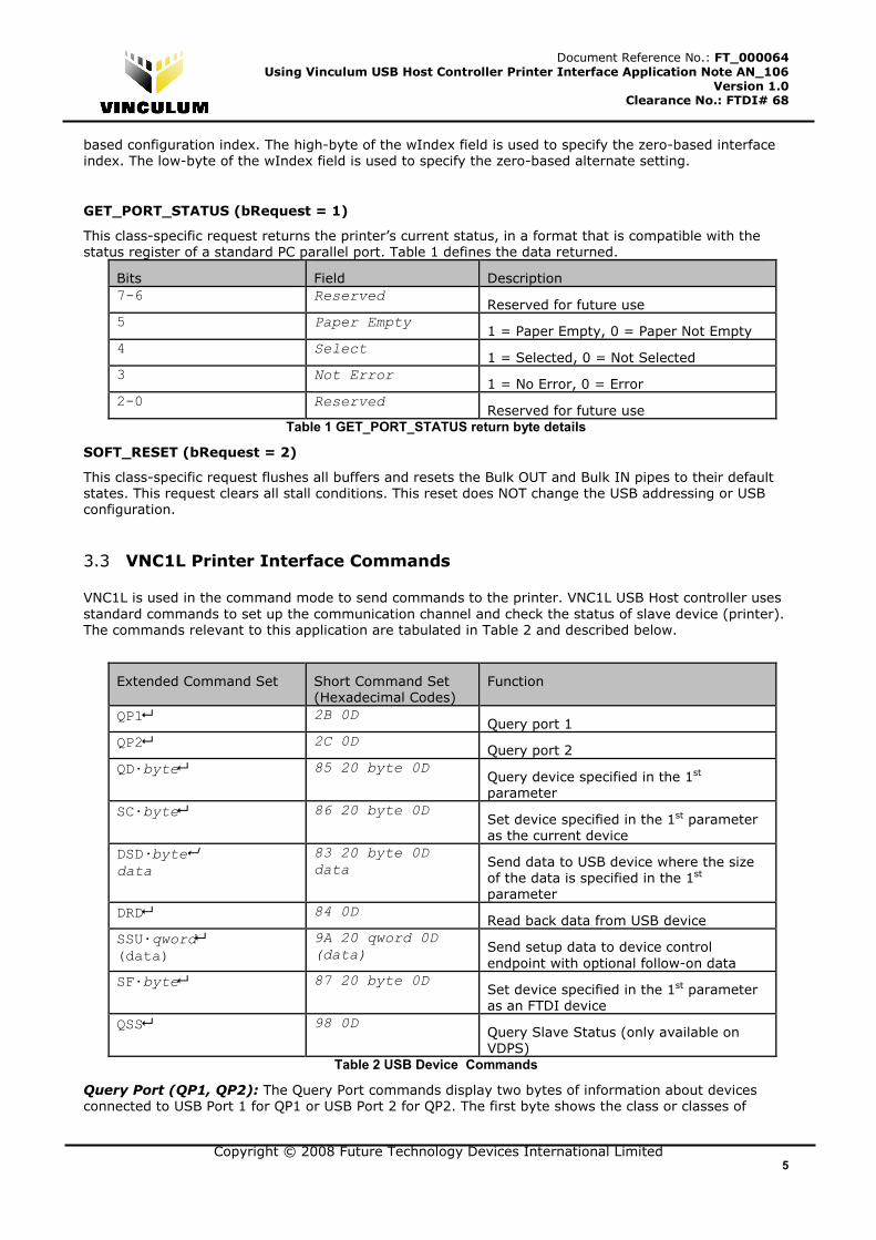
GET_PORT_STATUS (bRequest = 1)
This class-specific request returns the printer’s current status, in a format that is compatible with the
status register of a standard PC parallel port. Table 1 defines the data returned.
Bits Field Description
7-6 Reserved Reserved for future use
5 Paper Empty 1 = Paper Empty, 0 = Paper Not Empty
4 Select 1 = Selected, 0 = Not Selected
3 Not Error 1 = No Error, 0 = Error
2-0 Reserved Reserved for future use
Table 1 GET_PORT_STATUS return byte details
SOFT_RESET (bRequest = 2)
This class-specific request flushes all buffers and resets the Bulk OUT and Bulk IN pipes to their default
states. This request clears all stall conditions. This reset does NOT change the USB addressing or USB
configuration.
3.3 VNC1L Printer Interface Commands
VNC1L is used in the command mode to send commands to the printer. VNC1L USB Host controller uses
standard commands to set up the communication channel and check the status of slave device (printer).
The commands relevant to this application are tabulated in Table 2 and described below.
Extended Command Set Short Command Set
(Hexadecimal Codes)
Function
QP1� 2B 0D Query port 1
QP2� 2C 0D Query port 2
QD·byte� 85 20 byte 0D Query device specified in the 1st
parameter
SC·byte� 86 20 byte 0D Set device specified in the 1st parameter
as the current device
DSD·byte� data
83 20 byte 0D
data Send data to USB device where the size
of the data is specified in the 1st
parameter
DRD� 84 0D Read back data from USB device
SSU·qword� (data)
9A 20 qword 0D
(data) Send setup data to device control
endpoint with optional follow-on data
SF·byte� 87 20 byte 0D Set device specified in the 1st parameter
as an FTDI device
QSS� 98 0D Query Slave Status (only available on
VDPS)
Table 2 USB Device Commands
Query Port (QP1, QP2): The Query Port commands display two bytes of information about devices connected to USB Port 1 for QP1 or USB Port 2 for QP2. The first byte shows the class or classes of
Copyright © 2008 Future Technology Devices International Limited 6
Document Reference No.: FT_000064 Using Vinculum USB Host Controller Printer Interface Application Note AN_106
Version 1.0 Clearance No.: FTDI# 68
connected devices. The second byte is always zero. The connected devices bitmask is described in Table
3.
Bit Device Type
7 Hub Device on Port
6 Unknown Device
5 BOMS Class Device
4 CDC Class Device
3 HID Class Device
2 Printer Class Device
1 Reserved (always 0)
0 FTDI FT232 / FT245 / FT2232 Device
Table 3 Device Type Bit Definitions
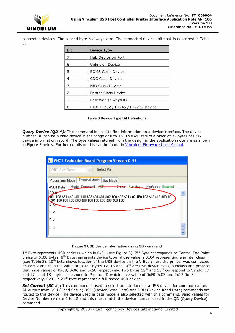
Query Device (QD #): This command is used to find information on a device interface. The device number ‘#’ can be a valid device in the range of 0 to 15. This will return a block of 32 bytes of USB
device information record. The byte values retuned from the design in the application note are as shown
in Figure 3 below. Further details on this can be found in Vinculum Firmware User Manual.
Figure 3 USB device information using QD command
1st Byte represents USB address which is 0x01 (see Figure 3). 2nd Byte corresponds to Control End Point
0 size of 0x08 bytes. 8th Byte represents device type whose value is 0x04 representing a printer class
(see Table 3). 10th byte shows location of the USB device on the V-Eval; here the printer was connected
on Port 2 and thus the value of 0x02. Bytes 12, 13 and 14th are USB device class, subclass and protocol
that have values of 0x08, 0x06 and 0x50 respectively. Two bytes 15th and 16th correspond to Vendor ID
and 17th and 18th byte correspond to Product ID which have value of 0xF0 0x03 and 0x12 0x13
respectively. 0x01 in 21st Byte represents a full-speed USB device.
Set Current (SC #): This command is used to select an interface on a USB device for communication. All output from SSU (Send Setup) DSD (Device Send Data) and DRD (Device Read Data) commands are
routed to this device. The device used in data mode is also selected with this command. Valid values for
Device Number (#) are 0 to 15 and this must match the device number used in the QD (Query Device)
command.
Copyright © 2008 Future Technology Devices International Limited 7
Document Reference No.: FT_000064 Using Vinculum USB Host Controller Printer Interface Application Note AN_106
Version 1.0 Clearance No.: FTDI# 68
Device Send Data (DSD): The DSD command sends a packet of data to a USB device. The target device must be set as the current device (using the SC command). The data sent to the device is taken
directly from the Monitor input. There is no conversion from AScii to binary nor is a carriage return
required after writing the data to the Monitor port. USB byte ordering applies to the data received. Up to
64 bytes can be transferred in a single packet.
VNC1L Printer Specific Commands
VNC1L implements following printer specific commands corresponding to USB printer class commands -
Printer Get Status (PGS) and Printer Soft Reset (PSR). See Table 4 for hex codes and details.
Extended Command Set Short Command Set
(Hexadecimal Codes)
Function
PGS� 81 0D Get printer status
PSR� 82 0D Printer soft reset
Table 4 VNC1L Printer Specific Commands
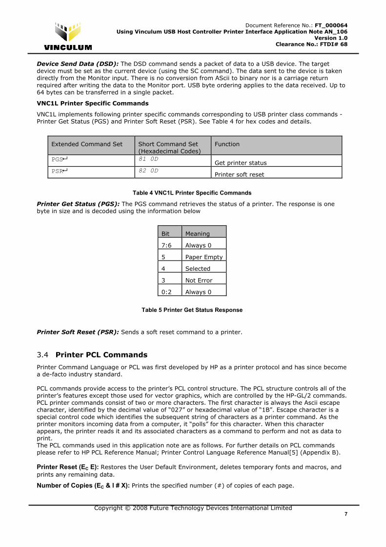
Printer Get Status (PGS): The PGS command retrieves the status of a printer. The response is one byte in size and is decoded using the information below
Bit Meaning
7:6 Always 0
5 Paper Empty
4 Selected
3 Not Error
0:2 Always 0
Table 5 Printer Get Status Response
Printer Soft Reset (PSR): Sends a soft reset command to a printer.
3.4 Printer PCL Commands
Printer Command Language or PCL was first developed by HP as a printer protocol and has since become
a de-facto industry standard.
PCL commands provide access to the printer’s PCL control structure. The PCL structure controls all of the
printer’s features except those used for vector graphics, which are controlled by the HP-GL/2 commands.
PCL printer commands consist of two or more characters. The first character is always the Ascii escape
character, identified by the decimal value of “027” or hexadecimal value of “1B”. Escape character is a
special control code which identifies the subsequent string of characters as a printer command. As the
printer monitors incoming data from a computer, it “polls” for this character. When this character
appears, the printer reads it and its associated characters as a command to perform and not as data to
print.
The PCL commands used in this application note are as follows. For further details on PCL commands
please refer to HP PCL Reference Manual; Printer Control Language Reference Manual[5] (Appendix B).
Printer Reset (EC E): Restores the User Default Environment, deletes temporary fonts and macros, and prints any remaining data.
Number of Copies (EC & l # X): Prints the specified number (#) of copies of each page.
Copyright © 2008 Future Technology Devices International Limited 8
Document Reference No.: FT_000064 Using Vinculum USB Host Controller Printer Interface Application Note AN_106
Version 1.0 Clearance No.: FTDI# 68
Page Size (EC & l # A): Designates the physical paper size which in turn defines the logical page. # = 2 - Letter (8.5" x 11")
Left Margin (EC & a # L): Sets the left margin to the left edge of the specified column. # = Column number
Right Margin (EC & a # M): Sets the right margin to the right edge of the specified column. # = Column number
Line Termination (EC & k # G): Controls the way the printer interprets CR, LF, and FF control codes. # = 0 - CR = CR, LF = LF, FF = FF
Font Selection by ID # (EC ( # X or EC ) # X): Selects a soft font using its specific ID #. EC ( # X - Designates soft font as primary. EC ) # X - Designates soft font as secondary. # = Font Identification number
Spacing (EC ( s # P – Primary, EC ) s # P – Secondary): Designates either a fixed or proportionally spaced font. # =0 means Fixed spacing, # - 1 means Proportional spacing
Pitch (EC ( s # H – Primary, EC ) s # H – Secondary): Designates the horizontal spacing of a fixed spaced font in terms of the number of characters per inch. # = Pitch in characters/inch
Stroke Weight (EC ( s # B – Primary, EC) s # B – Secondary): Designates the thickness or weight of the stroke that composes the characters of a font.
3.5 HC12 Firmware Details
We assume basic familiarity with H12 assembler tools. Further details on H12 assembler can be found in
H12 Assembler manual [6] (Appendix B).
3.5.1 Theory of Operation
The program begins by initializing the processor resources. Programmable resources include RAM
address location, I/O definitions, SPI, UART and EEPROM. Only the resources that are used in the project
need to be initialized. By default, the processor initializes resources to be disabled and I/O to be input
pins and SPI mode is enabled. The program is also configured for UART communication with the VNC1L
with possibility of allowing RS-232 communication at a later time.
After the system is initialized, the program enters the main loop, which scans for time based events or
asynchronous events. At any time, the main loop can be interrupted for processing interrupt events
such as timers or RS-232 input.
MAIN: This is the program loop that runs all of the routine operations of the system. This includes
waiting for time based functions, scanning for keys, and checking for new messages from the VNC1L.
Time based functions are triggered by setting “Flags” in the Timer_Flag variable. The timers interrupt
routine “TIMER:” sets the individual bits, or “Flags”, in the Timer_Flag variable based on how much time
has elapsed. There are time based events pre-configured for 0.1 sec, 0.5 sec, 1 sec, 0.1min, and 1 min
intervals.
For this demonstration, only a single key is being scanned. But note that for any keys that are used, a
debounce routine should be used to eliminate erroneous key presses. Keypads and switches are
notorious for ringing as the key is pressed and released. As soon as key is pressed, DSD command with
PCL control codes is given to VNC1L chip on SPI bus which results in printing the data on printer
connected on USB port of VNC1L.
The Main loop also scans the VNC1L for any new messages. When a new message is detected, it is read
and parsed to determine if any further action should be taken. For example, when a new device is
connected, it should be polled to indentify the device type and device number.
INTERRUPTS: Two interrupts are used for this demonstration. One is for timekeeping; the other is to
run the RS-232 interface. The CPU timer register is configured to increment every 4 bus clocks. The
bus is driven by a PLL and is configured for a 23.9616 MHz clock.
Copyright © 2008 Future Technology Devices International Limited 9
Document Reference No.: FT_000064 Using Vinculum USB Host Controller Printer Interface Application Note AN_106
Version 1.0 Clearance No.: FTDI# 68
TIMER: This routine is triggered once every 5990 timer ticks, or every 1 mS. Each of the mS interrupts
are counted and stored in variables so that the Timer_Flag bits can be set to identify periodic time
events.
The RS-232 interrupt is used to receive data from the USB port, which should be connected to a PC
running a terminal program at 115,200 baud. Each byte that is received triggers an interrupt that gets
the incoming character and stores it to a buffer. When a form feed command (0x0C) is received, the
incoming data is then sent to the VNC1L to be printed. If a form feed is not received, any data in the
input buffer is printed after timer based pre-configured timeouts.
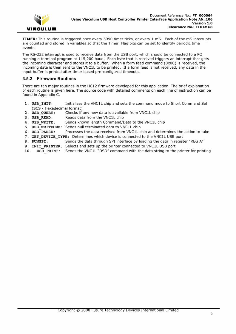
3.5.2 Firmware Routines
There are ten major routines in the HC12 firmware developed for this application. The brief explanation
of each routine is given here. The source code with detailed comments on each line of instruction can be
found in Appendix C.
1. USB_INIT: Initializes the VNC1L chip and sets the command mode to Short Command Set
(SCS - Hexadecimal format) 2. USB_QUERY: Checks if any new data is available from VNC1L chip
3. USB_READ: Reads data from the VNC1L chip
4. USB_WRITE: Sends known length Command/Data to the VNC1L chip
5. USB_WRITECMD: Sends null terminated data to VNC1L chip
6. USB_PARSE: Processes the data received from VNC1L chip and determines the action to take
7. GET_DEVICE_TYPE: Determines which device is connected to the VNC1L USB port
8. RUNSPI: Sends the data through SPI interface by loading the data in register “REG A”
9. INIT_PRINTER: Selects and sets up the printer connected to VNC1L USB port
10. USB_PRINT: Sends the VNC1L “DSD” command with the data string to the printer for printing

Copyright © 2008 Future Technology Devices International Limited 10
Document Reference No.: FT_000064 Using Vinculum USB Host Controller Printer Interface Application Note AN_106
Version 1.0 Clearance No.: FTDI# 68
4 Hardware Connections and Running the Demo
4.1 Jumper Settings
Figure 4 shows key components that need attention for this demo. To configure the V-Eval board for this
application, remove the jumper J7 (avoid SPI signal interference with FT2232 device on V-Eval Board)
Figure 4 V-Eval board - Key Components
Next, select SPI mode of operation for the monitor port by setting jumpers JP1 and JP2 (as shown in
Figure 5) according to settings in Table 6.
Figure 5 Jumpers for SPI mode selection
Copyright © 2008 Future Technology Devices International Limited 11
Document Reference No.: FT_000064 Using Vinculum USB Host Controller Printer Interface Application Note AN_106
Version 1.0 Clearance No.: FTDI# 68
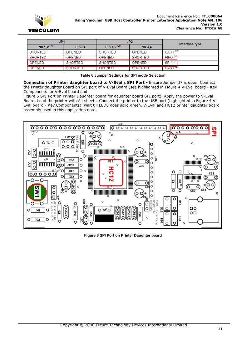
Table 6 Jumper Settings for SPI mode Selection
Connection of Printer daughter board to V-Eval’s SPI Port - Ensure Jumper J7 is open. Connect
the Printer daughter Board on SPI port of V-Eval Board (see highlighted in Figure 4 V-Eval board - Key
Components for V-Eval board and
Figure 6 SPI Port on Printer Daughter board for daughter board SPI port). Apply the power to V-Eval
Board. Load the printer with A4 sheets. Connect the printer to the USB port (highlighted in Figure 4 V-
Eval board - Key Components), wait till LED8 goes solid green. V-Eval and HC12 printer daughter board
assembly used in this application note.
Figure 6 SPI Port on Printer Daughter board
Copyright © 2008 Future Technology Devices International Limited 12
Document Reference No.: FT_000064 Using Vinculum USB Host Controller Printer Interface Application Note AN_106
Version 1.0 Clearance No.: FTDI# 68
Figure 7 V-Eval and Printer Daughter Board Assembly
4.2 LED Usage
LED7 and LED8 on V-Eval board are used for indicating various states of USB printer in this application.
Specifically various printer states are represented using LED states as shown below.
Power On: LED7 and LED8 flash alternately for 2 seconds. This is repeated until monitor connects
USB Printer Ready: LED7 off, LED8 on
USB Printer Removed: LED7 off, LED8 off
Commands from monitor Port to USB Printer: LED7 off, LED8 flashes
Commands from monitor Port with USB Printer removed: LED7 off, LED8 off
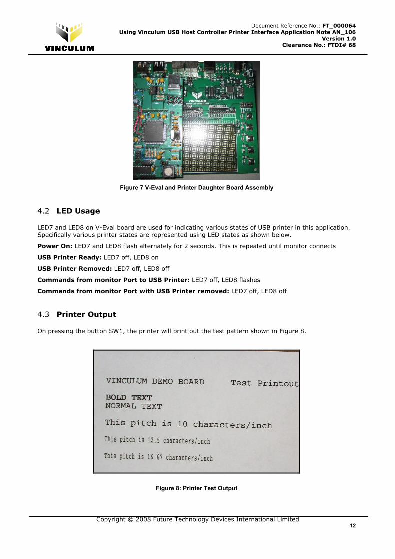
4.3 Printer Output
On pressing the button SW1, the printer will print out the test pattern shown in Figure 8.
Figure 8: Printer Test Output

Copyright © 2008 Future Technology Devices International Limited 13
Document Reference No.: FT_000064 Using Vinculum USB Host Controller Printer Interface Application Note AN_106
Version 1.0 Clearance No.: FTDI# 68
5 Summary
This application note demonstrates how a USB printer interface can be added to an embedded system
using Vinculum USB Host controller VNC1L. A 16-bit Freescale HC12 microcontroller has been used to
control the VNC1L chip using SPI interface on V-Eval board and give PCL commands to the printer.
Complete details of project, hardware, firmware details, step-by-step instructions for setting up the
hardware and running the application demo are included in this application note.
Copyright © 2008 Future Technology Devices International Limited 14
Document Reference No.: FT_000064 Using Vinculum USB Host Controller Printer Interface Application Note AN_106
Version 1.0 Clearance No.: FTDI# 68
6 Contact Information
Head Office – Glasgow, UK
Future Technology Devices International Limited
Unit 1, 2 Seaward Place, Centurion Business Park,
Glasgow G41 1HH
United Kingdom
Tel: +44 (0) 141 429 2777
Fax: +44 (0) 141 429 2758
E-mail (Sales) [email protected]
E-mail (Support) [email protected]
E-mail (General Enquiries) [email protected]
Web Site URL http://www.ftdichip.com
Web Shop URL http://www.ftdichip.com
Branch Office – Taipei, Taiwan
Future Technology Devices International Limited (Taiwan)
4F, No 18-3, Sec. 6 Mincyuan East Road
Neihu District
Taipei 114
Taiwan, R.O.C.
Tel: +886 (0) 2 8791 3570
Fax: +886 (0) 2 8791 3576
E-mail (Sales) [email protected]
E-mail (Support) [email protected]
E-mail (General Enquiries) [email protected]
Web Site URL http://www.ftdichip.com
Branch Office – Hillsboro, Oregon, USA
Future Technology Devices International Limited (USA)
7235 NW Evergreen Parkway, Suite 600
Hillsboro, OR 97123-5803
USA
Tel: +1 (503) 547 0988
Fax: +1 (503) 547 0987
E-Mail (Sales) [email protected]
E-Mail (Support) [email protected]
Web Site URL http://www.ftdichip.com
Distributor and Sales Representatives
Please visit the Sales Network page of the FTDI Web site for the contact details of our distributor(s) and
sales representative(s) in your country.
Disclaimer:
Vinculum is part of Future Technology Devices International Ltd. Neither the whole nor any part of the information contained in, or the
product described in this manual, may be adapted or reproduced in any material or electronic form without the prior written consent of the
copyright holder. This product and its documentation are supplied on an as-is basis and no warranty as to their suitability for any particular purpose is either made or implied. Future Technology Devices International Ltd will not accept any claim for damages howsoever arising as a
result of use or failure of this product. Your statutory rights are not affected. This product or any variant of it is not intended for use in any
medical appliance, device or system in which the failure of the product might reasonably be expected to result in personal injury. This
document provides preliminary information that may be subject to change without notice. No freedom to use patents or other intellectual property rights is implied by the publication of this document. Future Technology Devices International Ltd, Unit1, 2 Seaward Place,
Centurion Business Park, Glasgow G41 1HH United Kingdom. Scotland Registered Number: SC136640
Copyright © 2008 Future Technology Devices International Limited 15
Document Reference No.: FT_000064 Using Vinculum USB Host Controller Printer Interface Application Note AN_106
Version 1.0 Clearance No.: FTDI# 68
Appendix A – Acknowledgements
We would like to thank Lucio Simoni of JPC controls for collaboration on both hardware (daughter board)
design and firmware development for this application note. Special thanks for obtaining permission to
showcase their customer Quantifit’s Occupational Health Dynamics product as a part of this application
note.
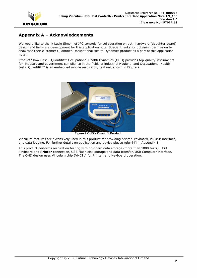
Product Show Case - Quantifit™ Occupational Health Dynamics (OHD) provides top-quality instruments
for industry and government compliance in the fields of industrial Hygiene and Occupational Health
tests. Quantifit ™ is an embedded mobile respiratory test unit shown in Figure 9.
Figure 9 OHD's Quantifit Product
Vinculum features are extensively used in this product for providing printer, keyboard, PC USB interface,
and data logging. For further details on application and device please refer [4] in Appendix B.
This product performs respiration testing with on-board data storage (more than 1000 tests), USB
keyboard and Printer connection, USB Flash disk storage and data transfer, USB Computer interface.
The OHD design uses Vinculum chip (VNC1L) for Printer, and Keyboard operation.

Copyright © 2008 Future Technology Devices International Limited 16
Document Reference No.: FT_000064 Using Vinculum USB Host Controller Printer Interface Application Note AN_106
Version 1.0 Clearance No.: FTDI# 68
Appendix B - References
1. Vinculum Website: The main website for the Vinculum family of USB Host Controllers on the FTDI
website http://www. ftdichip.com/
2. Vinculum Datasheet (DS_VNC1L-1A): Vinculum Embedded USB Host Controller IC Data Sheet
http://www. ftdichip.com/
3. USB Device Class Definition for Printing Devices
http://www.usb.org/developers/devclass_docs/usbprint11.pdf
4. Product Showcase: (OHD’s – Quantifit™)
http://expweb.magiccitywebs.net/OHD/default.aspx?id=798
5. HP PCL Reference Manual; Printer Control Language Reference Manual
http://h20000.www2.hp.com/bc/docs/support/SupportManual/bpl13210/bpl13210.pdf
6. HC12 Assembler User Manual
http://www.freescale.com/files/microcontrollers/doc/user_guide/MCUEZASM12.pdf
Copyright © 2008 Future Technology Devices International Limited 17
Document Reference No.: FT_000064 Using Vinculum USB Host Controller Printer Interface Application Note AN_106
Version 1.0 Clearance No.: FTDI# 68
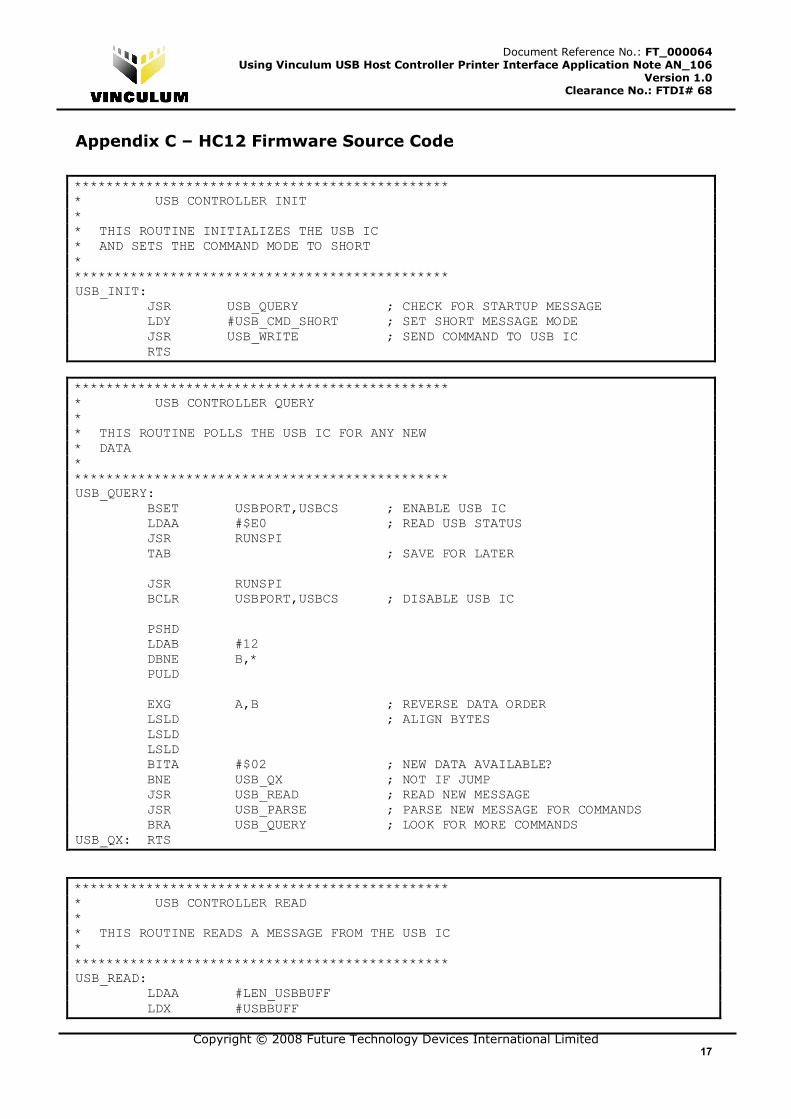
Appendix C – HC12 Firmware Source Code
*********************************************** * USB CONTROLLER INIT * * THIS ROUTINE INITIALIZES THE USB IC * AND SETS THE COMMAND MODE TO SHORT * *********************************************** USB_INIT: JSR USB_QUERY ; CHECK FOR STARTUP MESSAGE LDY #USB_CMD_SHORT ; SET SHORT MESSAGE MODE JSR USB_WRITE ; SEND COMMAND TO USB IC RTS
*********************************************** * USB CONTROLLER QUERY * * THIS ROUTINE POLLS THE USB IC FOR ANY NEW * DATA * *********************************************** USB_QUERY: BSET USBPORT,USBCS ; ENABLE USB IC LDAA #$E0 ; READ USB STATUS JSR RUNSPI TAB ; SAVE FOR LATER JSR RUNSPI BCLR USBPORT,USBCS ; DISABLE USB IC PSHD LDAB #12 DBNE B,* PULD EXG A,B ; REVERSE DATA ORDER LSLD ; ALIGN BYTES LSLD LSLD BITA #$02 ; NEW DATA AVAILABLE? BNE USB_QX ; NOT IF JUMP JSR USB_READ ; READ NEW MESSAGE JSR USB_PARSE ; PARSE NEW MESSAGE FOR COMMANDS BRA USB_QUERY ; LOOK FOR MORE COMMANDS USB_QX: RTS
*********************************************** * USB CONTROLLER READ * * THIS ROUTINE READS A MESSAGE FROM THE USB IC * *********************************************** USB_READ: LDAA #LEN_USBBUFF LDX #USBBUFF
Copyright © 2008 Future Technology Devices International Limited 18
Document Reference No.: FT_000064 Using Vinculum USB Host Controller Printer Interface Application Note AN_106
Version 1.0 Clearance No.: FTDI# 68
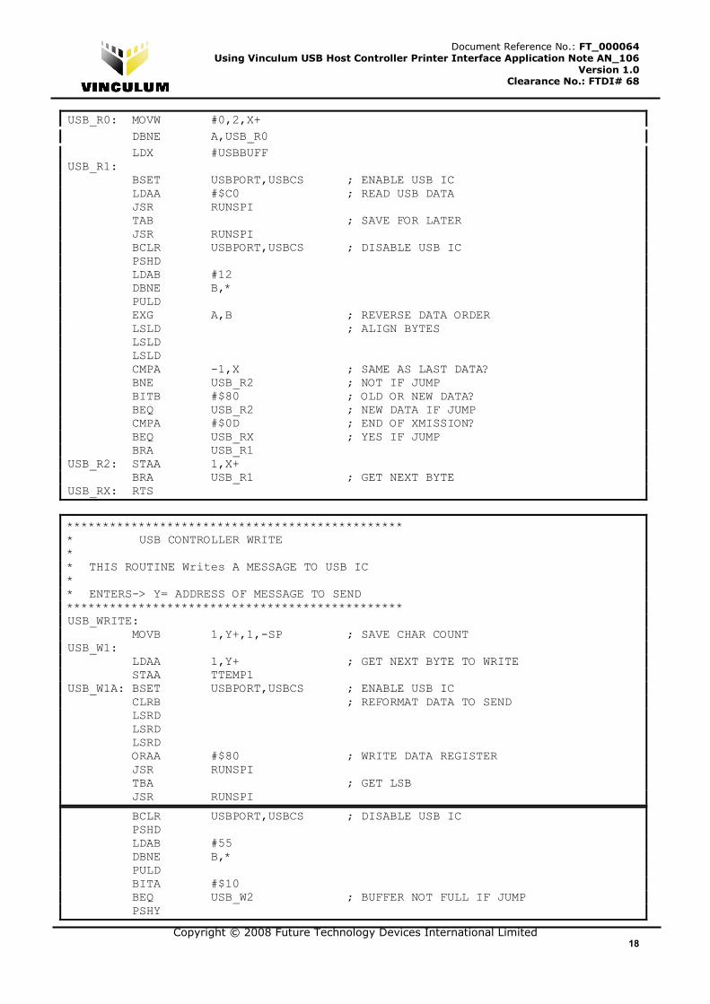
USB_R0: MOVW #0,2,X+
DBNE A,USB_R0
LDX #USBBUFF USB_R1: BSET USBPORT,USBCS ; ENABLE USB IC LDAA #$C0 ; READ USB DATA JSR RUNSPI TAB ; SAVE FOR LATER JSR RUNSPI BCLR USBPORT,USBCS ; DISABLE USB IC PSHD LDAB #12 DBNE B,* PULD EXG A,B ; REVERSE DATA ORDER LSLD ; ALIGN BYTES LSLD LSLD CMPA -1,X ; SAME AS LAST DATA? BNE USB_R2 ; NOT IF JUMP BITB #$80 ; OLD OR NEW DATA? BEQ USB_R2 ; NEW DATA IF JUMP CMPA #$0D ; END OF XMISSION? BEQ USB_RX ; YES IF JUMP BRA USB_R1 USB_R2: STAA 1,X+ BRA USB_R1 ; GET NEXT BYTE USB_RX: RTS
*********************************************** * USB CONTROLLER WRITE * * THIS ROUTINE Writes A MESSAGE TO USB IC * * ENTERS-> Y= ADDRESS OF MESSAGE TO SEND *********************************************** USB_WRITE: MOVB 1,Y+,1,-SP ; SAVE CHAR COUNT USB_W1: LDAA 1,Y+ ; GET NEXT BYTE TO WRITE STAA TTEMP1 USB_W1A: BSET USBPORT,USBCS ; ENABLE USB IC CLRB ; REFORMAT DATA TO SEND LSRD LSRD LSRD ORAA #$80 ; WRITE DATA REGISTER JSR RUNSPI TBA ; GET LSB JSR RUNSPI
BCLR USBPORT,USBCS ; DISABLE USB IC PSHD LDAB #55 DBNE B,* PULD BITA #$10 BEQ USB_W2 ; BUFFER NOT FULL IF JUMP PSHY
Copyright © 2008 Future Technology Devices International Limited 19
Document Reference No.: FT_000064 Using Vinculum USB Host Controller Printer Interface Application Note AN_106
Version 1.0 Clearance No.: FTDI# 68
JSR USB_QUERY PULY
LDAA TTEMP1
BRA USB_W1A ; RE-TRANSMIT USB_W2: DEC 0,SP ; DONE WITH COMMAND? BNE USB_W1 ; NO-GET NEXT BYTE LEAS 1,SP ; DEALLOCATE LOOP COUNTER USB_WX: RTS
*********************************************** * USB CONTROLLER WRITE * * THIS ROUTINE SENDS NULL TREMINATED DATA to USB IC * * ENTERS-> Y= ADDRESS OF MESSAGE TO SEND *********************************************** USB_WRITECMD: USB_WC1: LDAA 1,Y+ ; GET NEXT BYTE TO WRITE BEQ USB_WCX ; DONE IF JUMP BSET USBPORT,USBCS ; ENABLE USB IC CLRB ; REFORMAT DATA TO SEND LSRD LSRD LSRD ORAA #$90 ; WRITE STATUS REGISTER JSR RUNSPI TBA ; GET LSB JSR RUNSPI BCLR USBPORT,USBCS ; DISABLE USB IC PSHD LDAB #55 DBNE B,* PULD BRA USB_WC1 ; GET NEXT BYTE USB_WCX: RTS
*********************************************** * PARSE USB RESPONSE * * THIS ROUTINE LOOKS AT THE COMMANDS SENT FROM * THE USB CONTROLLER AND DETERMINES WHAT ACTION * TO TAKE. * *********************************************** USB_PARSE: LDAB USB_RESP ; WAITING RESPONSE FROM COMMAND?

Copyright © 2008 Future Technology Devices International Limited 20
Document Reference No.: FT_000064 Using Vinculum USB Host Controller Printer Interface Application Note AN_106
Version 1.0 Clearance No.: FTDI# 68
BEQ FIND_USB0 ; NOT IF JUMP CLR USB_RESP ; CLEAR RESPONSE MODE CMPB #1 ; QUERY RESPONSE?
BNE USB_P1A ; NOT IF JUMP
LDY #USB1_TYPE ; SAVE TO APPROPRIATE DEVICE LDAB USBCMD LDAA USBBUFF ; GET DEVICE TYPE JSR GET_DEVICE_TYPE ; FIND WHAT TYPE OF DEVICE IS CONNECTED STAA B,Y ; SAVE DEVICE TYPE BCLR FLAG4,#$10 ; DEFAULT TO NOT KEYBOARD DEVICE CMPA #$02 ; KEYBOARD? BNE USB_P1X ; NOT IF JUMP BSET FLAG4,#$10 ; SET KEYBOARD DEVICE READ LDAB USBCMD ; GET WHICH PORT IS PLUGGED IN LDY #DEVICE_SET1 ; COMMAND TABLE JSR GET_COMMAND JSR USB_WRITE ; ACTIVATE APPROPRIATE PORT BRA USB_P1X USB_P1A: LDD USBBUFF ; KEYBOARD RESPONSE PARSE CPD #$080D ; 8 BYTES RECEIVED? BNE USB_P1X ; NOT IF JUMP LDD USBBUFF+10 ; CORRECT END STRING? CPD #$3E0D BNE USB_P1X ; NOT IF JUMP USB_P1X: JMP USBPX ; EXIT FIND_USB1: TST 0,Y ; END OF MATCHING STRING? BEQ FIND_USBOK ; MORE DATA ENTERED THAN TO COMARE WITH LDAA 0,X ; GET FIRST CHAR OF COMMAND CMPA #$61 ; LOWER CASE LETTER? BLO FIND_USB1A ; NOT IF JUMP CMPA #$7A ; a-z? BHI FIND_USB1A ; NOT IF JUMP ANDA #$DF ; CONVERT TO UPPER CASE FIND_USB1A: CMPA 0,Y ; MATCHES TABLE ENTRY? BNE FIND_UNEXT ; NOT IF JUMP LEAX 1,X ; MOVE TO NEXT CHAR IN BUFFER LEAY 1,Y ; MOVE TO NEXT CHAR IN TABLE BRA FIND_USB1 ; KEEP TESTING MORE CHARS FIND_USBOK: CLRA ; CLEAR MSB PULB ; RESTORE INDEX POINTER (LSB) LEAS 2,SP ; DEALLOCATE LOCAL BRA USBP0 FIND_USBERR: ; END OF INCOMING CHARS, NO MATCH LEAS 3,SP ; DEALLOCATE LOCALS BRA USBPX USBPX: RTS
*********************************************** * GET USB DEVICE TYPE FROM MASK * * BIT MASK DESC * 0 - 1 - FTDI DEVICE * 1 - 2 - RESERVED * 2 - 4 - PRINTER CLASS DEVICE * 3 - 8 - HID CLASS DEVICE (KEYBOARD)
Copyright © 2008 Future Technology Devices International Limited 21
Document Reference No.: FT_000064 Using Vinculum USB Host Controller Printer Interface Application Note AN_106
Version 1.0 Clearance No.: FTDI# 68
* 4 - 10 - CDC CLASS DEVICE * 5 - 20 - BOMS CLASS DEVICE (FLASH DRIVE) * 6 - 40 - UNKNOWN DEVICE
* 7 - 80 - HUB DEVICE
* * * ENTERS-> A= DEVICE TYPE * * RETURNS-> A=0 (NOTHING CONNECTED) * 1 (PRINTER) * 2 (KEYBOARD) * 3 (FLASH DISK) * 4 (OTHER -UNRECOGNIZED) * *********************************************** GET_DEVICE_TYPE: BITA #$04 ; PRINTER? BEQ GET_DT1 ; NOT IF JUMP LDAA #$1 ; YES, SET PRINTER TYPE BRA GET_DTX ; EXIT GET_DT1: BITA #$08 ; HID DEVICE (KEYBOARD)? BEQ GET_DT2 ; NOT IF JUMP LDAA #$02 ; SET KEYBOARD DEVICE BRA GET_DTX GET_DT2: BITA #$20 ; FLASH DISK? BEQ GET_DT3 ; NOT IF JUMP LDAA #$03 ; SET FLASH DISK BRA GET_DTX GET_DT3: LDAA #$04 ; SET UNKNOWN DEVICE TYPE GET_DTX: RTS
********************************************* * RUNSPI * THIS ROUTINE SENDS THE DATA IN REG A * AND RETURNS DATA IN REGISTER A ********************************************* RUNSPI: STAA SP0DR ; SEND DATA * BRCLR SP0SR,#$80,* ; WAIT FOR DATA RETURNED * LDAA SP0SR ; CLEAR FLAGS LDAA SP0DR ; READ RETURNED DATA * RTS ; DONE
********************************************************* * INITIALIZE PRINTER * * THIS ROUTINE RESETS THE PRINTER AND SETS IT TO ASCII * PRINT (PCL3 LANGUAGE, HP PRINTERS ONLY) * * RETURNS WITH Z SET IF PRINTER OK * Z CLR IF NOT READY OR NOT PRESENT
Copyright © 2008 Future Technology Devices International Limited 22
Document Reference No.: FT_000064 Using Vinculum USB Host Controller Printer Interface Application Note AN_106
Version 1.0 Clearance No.: FTDI# 68
* ********************************************************* INIT_PRINTER: LDAA USB1_TYPE ; IS PORT 1 PRINTER?
CMPA #$01
LBNE PINITY ; NOT IF JUMP LDY #DEVICE_SET1 ; SET CURRENT DEVICE BRA PINIT2 PINIT1: LDAA USB2_TYPE ; IS PORT 2 PRINTER? CMPA #$01 LBNE PINITY ; NO-ERROR LDY #DEVICE_SET2 ; SET PORT 2 AS ACTIVE DEVICE PINIT2: JSR USB_WRITE LDY #HP_SETUP1 ; SEND PRINT ENABLE COMMAND JSR USB_WRITE JSR VAR_30MS JSR USB_QUERY LDY #HP_SETUP ; SEND PRINT ENABLE COMMAND JSR USB_WRITE JSR VAR_30MS JSR USB_QUERY CLRA ; RETURN ZERO FOR PRINTER READY BRA PINITX PINITY: LDAA #$FF ; RETURN NON-ZERO FOR ERROR PINITX: RTS
************************************************************* * USB PRINT * * THIS ROUTINE SENDS AN ASCII STRING TO THE PRINTER * * THE STRING MUST BE NULL TERMINATED * * THE USB COMMAND DSD IS ADDED TO THE BEGINNING OF THE STRING ************************************************************* USB_PRINT: MOVW #$8320,PRINT_BUFF+1 ; SETUP DEVICE SEND DATA COMMAND MOVB #$0D,PRINT_BUFF+4 ; SETUP CARRIAGE RETURN LDAA #$FF ; INIT CHAR COUNTER LDX #PRINT_BUFF+5 ; START OF PRINT BUFFER DATA F03S1: INCA ; COUNT CHARS IN STRING LDAB 1,Y+ STAB 1,X+ BNE F03S1 ; LOOP TILL END OF STRING STAA PRINT_BUFF+3 ; SAVE # CHARS TO SEND ADDA #4 ; ADD # CONTROL BYTES …contd… STAA PRINT_BUFF PSHY ; SAVE SENT STRING ADDRESS LDY #PRINT_BUFF ; GET START OF COMMAND JSR USB_WRITE ; SEND TO PRINTER PULY F03X: RTS

Copyright © 2008 Future Technology Devices International Limited 23
Document Reference No.: FT_000064 Using Vinculum USB Host Controller Printer Interface Application Note AN_106
Version 1.0 Clearance No.: FTDI# 68
Appendix D – Revision History
Version 1.00 First Release 24/11/2008