Embed Size (px)
Citation preview
Future Technology Devices International Limited (FTDI)
373 Scotland Street, Glasgow G5 8QB United Kingdom Tel.: +44 (0) 141 429 2777 Fax: + 44 (0) 141 429 2758
E-Mail (Support): [email protected] Web: http://www.ftdichip.com
Copyright © 2008 Future Technology Devices International Limited
Future Technology Devices International Ltd.
Application Note AN_105
FTDI Device EEPROM Programming
Using a Vinculum VNC1L
Document Reference No.: FT_000078
Version 1.00
Issue Date: 2008-09-23
This document describes a C application that uses the VNC1L to program the EEPROM of an
FTDI peripheral device.
Copyright © 2008 Future Technology Devices International Limited 1
Document Reference No.: FT_000078 FTDI Device EEPROM Programming Using a Vinculum VNC1L Application Note AN_105
Version 1.00 Clearance No.: FTDI# 59
Table of Contents
1 Introduction............................................................................................ 2
1.1 Conventions ......................................................................................................... 2
1.2 Acronyms and Abbreviations ............................................................................. 3
2 Project Setup ......................................................................................... 4
2.1 Hardware Setup ................................................................................................... 4
2.2 Software Setup .................................................................................................... 5
2.2.1 TTL-232R-3V3 Drivers ............................................................................................................ 5
2.2.2 VNC1L Firmware ..................................................................................................................... 5
2.2.3 Alternative Application Code ................................................................................................... 5
3 EEPROM Firmware Commands ............................................................ 6
3.1 FTDI Erase EEPROM (FEE) ................................................................................. 6
3.2 Write EEPROM (FEW) .......................................................................................... 6
3.3 Read EEPROM (FER) ........................................................................................... 6
4 Application Code ................................................................................... 7
4.1 Subroutines for Setting up and Connecting to the TTL-232R-3V3 .................. 7
4.2 Subroutines for Setting up the VNC1L .............................................................. 7
4.2.1 Queue Status ........................................................................................................................... 8
4.2.2 Read Responses from VNC1L ................................................................................................ 8
4.2.3 Write Firmware commands to VNC1L ..................................................................................... 9
4.2.4 Shortened Command Set command (SCS) .......................................................................... 10
4.2.5 Firmware Version command (FWV) ...................................................................................... 10
4.2.6 Query Port command (QP) .................................................................................................... 10
4.2.7 Select Interface command (SC) ............................................................................................ 11
4.2.8 Query Device command (QD) ............................................................................................... 11
4.3 Subroutines for Reading and Writing to the EEPROM ................................... 13
4.3.1 Reading from an EEPROM (FER) ......................................................................................... 13
4.3.2 Writing to an EEPROM (FEW) .............................................................................................. 14
4.3.3 Writing to the EEPROM of an FTxxxR chip ........................................................................... 15
4.3.4 Checksum .............................................................................................................................. 17
5 Contact Information............................................................................. 18
Appendix A - References .......................................................................... 19
Appendix B - Revision History .................................................................. 20

Copyright © 2008 Future Technology Devices International Limited 2
Document Reference No.: FT_000078 FTDI Device EEPROM Programming Using a Vinculum VNC1L Application Note AN_105
Version 1.00 Clearance No.: FTDI# 59
1 Introduction
The VNC1L is a USB host controller IC which allows data to be transferred via USB to an FTDI peripheral device (FTxxx). The FTDI devices may use an EEPROM to store USB device descriptors that can be
programmed over the USB. Programming is commonly done by connecting the FTDI device to a PC,
installing the required FTDI drivers and using the driver API functions to program the EEPROM of the
device. This application note describes how to configure the VNC1L to program the EEPROM of an FTDI device.
Firmware available for the VNC1L allows the user to read, write and erase the EEPROM of an FTDI device. These firmware commands can be used to reprogram the VID, PID, serial number, manufacturer string
and description string within the EEPROM of all existing FTDI peripheral devices connected to the VNC1L.
This can be achieved using a C application on a PC. The example code for Microsoft® Visual Studio® 2008
is available by request under NDA. Contact [email protected] .
Any software code examples given in this document are for information only. The examples are not
guaranteed and are not supported by FTDI.
1.1 Conventions
The following conventions are used in this document:
Convention Description
Monospaced type Indicates input or output from the monitor.
Boldface monospaced type Indicates input supplied by the user.
Italic monospaced type Indicates binary characters (ASCII values of characters).
Important Signals that the information supplied is
important.
Note Provide additional information about a topic.
Warning Indicate potential damage to equipment or
loss of data.
: Is used to show a range. For instance, a
range of bits 15:9 is bits 15 to 9 (inclusive)
of a binary value.
VNC1L Indicated information specific to the VNC1L.
� carriage return (0x0D).
� space (0x20).
d Represents a single decimal character (0 to 9).
x Represents a single hexadecimal character
(0 to 9 and A to F).
c Represents a binary character (0x00 to
0xFF).
<sp> space
Copyright © 2008 Future Technology Devices International Limited 3
Document Reference No.: FT_000078 FTDI Device EEPROM Programming Using a Vinculum VNC1L Application Note AN_105
Version 1.00 Clearance No.: FTDI# 59
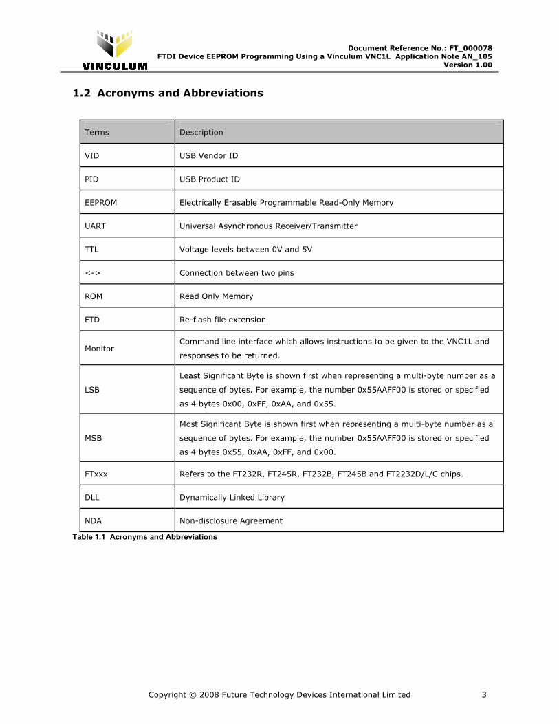
1.2 Acronyms and Abbreviations
Terms Description
VID USB Vendor ID
PID USB Product ID
EEPROM Electrically Erasable Programmable Read-Only Memory
UART Universal Asynchronous Receiver/Transmitter
TTL Voltage levels between 0V and 5V
<-> Connection between two pins
ROM Read Only Memory
FTD Re-flash file extension
Monitor Command line interface which allows instructions to be given to the VNC1L and
responses to be returned.
LSB
Least Significant Byte is shown first when representing a multi-byte number as a
sequence of bytes. For example, the number 0x55AAFF00 is stored or specified
as 4 bytes 0x00, 0xFF, 0xAA, and 0x55.
MSB
Most Significant Byte is shown first when representing a multi-byte number as a
sequence of bytes. For example, the number 0x55AAFF00 is stored or specified
as 4 bytes 0x55, 0xAA, 0xFF, and 0x00.
FTxxx Refers to the FT232R, FT245R, FT232B, FT245B and FT2232D/L/C chips.
DLL Dynamically Linked Library
NDA Non-disclosure Agreement
Table 1.1 Acronyms and Abbreviations
Copyright © 2008 Future Technology Devices International Limited 4
Document Reference No.: FT_000078 FTDI Device EEPROM Programming Using a Vinculum VNC1L Application Note AN_105
Version 1.00 Clearance No.: FTDI# 59
2 Project Setup
2.1 Hardware Setup
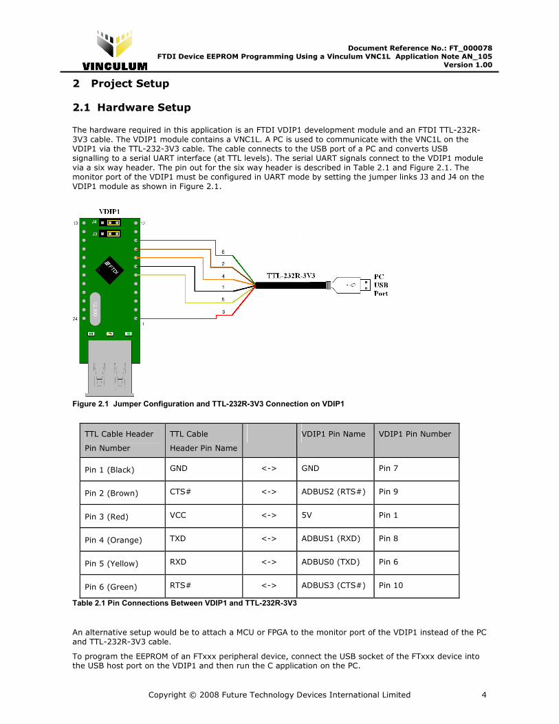
The hardware required in this application is an FTDI VDIP1 development module and an FTDI TTL-232R-
3V3 cable. The VDIP1 module contains a VNC1L. A PC is used to communicate with the VNC1L on the
VDIP1 via the TTL-232-3V3 cable. The cable connects to the USB port of a PC and converts USB signalling to a serial UART interface (at TTL levels). The serial UART signals connect to the VDIP1 module
via a six way header. The pin out for the six way header is described in Table 2.1 and Figure 2.1. The monitor port of the VDIP1 must be configured in UART mode by setting the jumper links J3 and J4 on the
VDIP1 module as shown in Figure 2.1.
Figure 2.1 Jumper Configuration and TTL-232R-3V3 Connection on VDIP1
TTL Cable Header
Pin Number
TTL Cable
Header Pin Name
VDIP1 Pin Name VDIP1 Pin Number
Pin 1 (Black) GND <-> GND Pin 7
Pin 2 (Brown) CTS# <-> ADBUS2 (RTS#) Pin 9
Pin 3 (Red) VCC <-> 5V Pin 1
Pin 4 (Orange) TXD <-> ADBUS1 (RXD) Pin 8
Pin 5 (Yellow) RXD <-> ADBUS0 (TXD) Pin 6
Pin 6 (Green) RTS# <-> ADBUS3 (CTS#) Pin 10
Table 2.1 Pin Connections Between VDIP1 and TTL-232R-3V3
An alternative setup would be to attach a MCU or FPGA to the monitor port of the VDIP1 instead of the PC
and TTL-232R-3V3 cable.
To program the EEPROM of an FTxxx peripheral device, connect the USB socket of the FTxxx device into the USB host port on the VDIP1 and then run the C application on the PC.
Copyright © 2008 Future Technology Devices International Limited 5
Document Reference No.: FT_000078 FTDI Device EEPROM Programming Using a Vinculum VNC1L Application Note AN_105
Version 1.00 Clearance No.: FTDI# 59
Note: An FTxxxB and FT2232D/C/L device must have an EEPROM connected to the IC. Ensure that when
using an FTxxxB or FT2232D/C/L device that there is an EEPROM connected to the device before attempting to program the EEPROM using the VNC1L.
2.2 Software Setup
2.2.1 TTL-232R-3V3 Drivers
The TTL-232R-3V3 cable requires its own drivers. These drivers need to be installed on the PC. The
drivers for the cable are available from the Drivers section of the FTDI website. Ensure that the drivers for the correct PC operating system are used.
Sending firmware commands to the VNC1L requires an application that transmits data down the TTL-
232R-3V3 cable. The FTDI D2XX Direct Driver allows the application software to interface with the
FT232R IC which is integrated within the TTL-232R-3V3 cable. The FTD2XX.DLL provides functions which allow the firmware commands to communicate with the VNC1L from the PC. An explanation of the
application code that sends the firmware commands to the VNC1L is given in section 4.
2.2.2 VNC1L Firmware
There are a number of VNC1L firmware options. The VDIP1 module uses the VDAP firmware. The firmware required for the EEPROM commands must be at least VDAP version 3.56 as the EEPROM
commands needed for this application were not available in earlier VDAP revisions.
If it is necessary to upgrade the VDAP software, please refer to the Vinculum Data Sheet for details of
how to do this.
2.2.3 Alternative Application Code
An alternative could be to attach a MCU or FPGA to control the VNC1L. This would not require the TTL-
232R-3V3 cable or PC so there would be no need to install the drivers that are mentioned in Section
2.2.1. Instead the MCU or FPGA would require firmware programmed onto them that would send the
same firmware commands to the VNC1L as explained in the application code in Section 4. The main advantage of this is that the device would not require a PC to program the EEPROM of the FTxxx devices
making the programmer application portable.
Copyright © 2008 Future Technology Devices International Limited 6
Document Reference No.: FT_000078 FTDI Device EEPROM Programming Using a Vinculum VNC1L Application Note AN_105
Version 1.00 Clearance No.: FTDI# 59
3 EEPROM Firmware Commands
The VNC1L commands for reading, writing, and erasing the FTxxx chips EEPROM are referenced in Table 3.1. See the Vinculum Firmware Manual for the complete command set.
Extended Command Set Short Command Set
(Hexadecimal codes)
Function
FEE� 95 0D Erase EEPROM
FEW <sp> Address (1 byte), Data
(MSB first)(2 bytes)�
96 20 Address (1 byte),
Data (2 bytes), 0D Write EEPROM
FER <sp> Address (1 Byte)� 97 20 Address (1 byte),
0D Read EEPROM
Table 3.1 EEPROM access commands
3.1 FTDI Erase EEPROM (FEE)
Parameters: None.
Erase an external EEPROM (93C46, 93C56 or 93C66) attached to either an FT2xxB or FT2232D/C/L device. This command has no effect on the inbuilt EEPROM of the FT2xxR.
Error Codes: None.
3.2 Write EEPROM (FEW)
Parameters:
Address – 1 Byte: EEPROM address to be accessed.
Data – 2 Bytes: The data to be sent to the specified address, MSB first.
This command specifies an address and writes 2 bytes of data to that address. The access is word
aligned.
Error Codes: None.
3.3 Read EEPROM (FER)
Parameters:
Address - Byte: EEPROM address to be accessed.
This command reads back two bytes from the specified address. The data is returned MSB first.
Error Codes: None.

Copyright © 2008 Future Technology Devices International Limited 7
Document Reference No.: FT_000078 FTDI Device EEPROM Programming Using a Vinculum VNC1L Application Note AN_105
Version 1.00 Clearance No.: FTDI# 59
4 Application Code
The following example details software which sets up a user interface to modify the VID, PID, serial number, manufacturer string and description string of the FTxxx EEPROM. The firmware commands used
throughout this application note are documented in the Vinculum Firmware User Manual. The application
software code that this application note is based on is only available by request under NDA. Contact
4.1 Subroutines for Setting up and Connecting to the TTL-232R-3V3
The code uses the D2XX DLL API functions to access the TTL-232R-3V3 cable. The full API function set is
documented in the D2XX programmer’s guide. The VNC1L UART monitor port has default interface
parameters that require to be configured in the TTL-232R-3V3 cable in order to access the VNC1L’s
monitor port. The FT_Open function opens the TTL-232R-3V3 cable for communication.
Parameters Values
Baud Rate 9600
Data Bits 8
Stop Bits 1
Parity None
Flow Control Hardware (RTS/CTS)
Monitor Mode ASCII and Extended Command Mode
Table 4.1 VNC1L’s Monitor Default Setup
To setup the parameters to match the VNC1L default parameters (see Table 4.1) the following subroutine
needs to be called.
void ConfigPort(DWORD BaudRate) { //set baud rate Status = FT_SetBaudRate(FtHandle,BaudRate); //set serial parameters Status = FT_SetDataCharacteristics(FtHandle, FT_BITS_8, FT_STOP_BITS_1, FT_PARITY_NONE); //set RTS line of TTL 232R Status = FT_SetRts(FtHandle); //set flow control to RTS/CTS Status = FT_SetFlowControl(FtHandle, FT_FLOW_RTS_CTS, 0, 0); } Figure 4.1 Configure Port Code
This will establish a connection between the TTL-232R-3V3 cable and the VDIP1 module.
4.2 Subroutines for Setting up the VNC1L
When the connection between the VDIP1 and TTL-232R-3V3 cable has been established, the VNC1L then
requires to be configured to establish a connection with the FTxxx device attached to the USB port 2 of the VDIP1. The VNC1L operates by receiving firmware commands via the monitor port to perform a
certain function. When the VNC1L receives and processes a firmware command it returns a message to the monitor port that lets the device connected to the monitor port know if the function was completed or
not. The subroutines described in 4.2.1 – 4.2.8 are required to make sure that the VNC1L is setup to communicate with the FTxxx device and ready to start the EEPROM firmware commands.
Copyright © 2008 Future Technology Devices International Limited 8
Document Reference No.: FT_000078 FTDI Device EEPROM Programming Using a Vinculum VNC1L Application Note AN_105
Version 1.00 Clearance No.: FTDI# 59
4.2.1 Queue Status
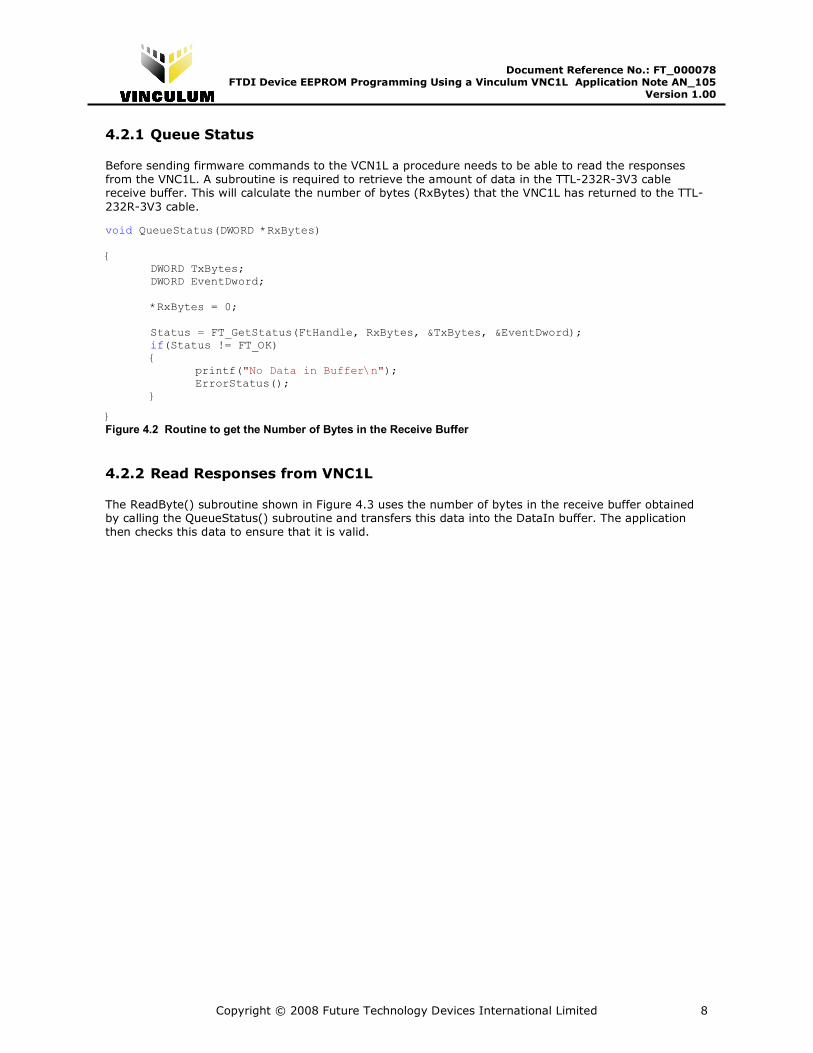
Before sending firmware commands to the VCN1L a procedure needs to be able to read the responses
from the VNC1L. A subroutine is required to retrieve the amount of data in the TTL-232R-3V3 cable receive buffer. This will calculate the number of bytes (RxBytes) that the VNC1L has returned to the TTL-
232R-3V3 cable.
void QueueStatus(DWORD *RxBytes) { DWORD TxBytes; DWORD EventDword; *RxBytes = 0; Status = FT_GetStatus(FtHandle, RxBytes, &TxBytes, &EventDword); if(Status != FT_OK) { printf("No Data in Buffer\n"); ErrorStatus(); }
} Figure 4.2 Routine to get the Number of Bytes in the Receive Buffer
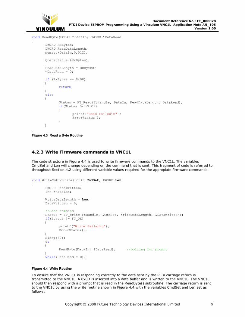
4.2.2 Read Responses from VNC1L
The ReadByte() subroutine shown in Figure 4.3 uses the number of bytes in the receive buffer obtained by calling the QueueStatus() subroutine and transfers this data into the DataIn buffer. The application
then checks this data to ensure that it is valid.
Copyright © 2008 Future Technology Devices International Limited 9
Document Reference No.: FT_000078 FTDI Device EEPROM Programming Using a Vinculum VNC1L Application Note AN_105
Version 1.00 Clearance No.: FTDI# 59
void ReadByte(UCHAR *DataIn, DWORD *DataRead) { DWORD RxBytes; DWORD ReadDataLength; memset(DataIn,0,512); QueueStatus(&RxBytes); ReadDataLength = RxBytes; *DataRead = 0; if (RxBytes == 0x00) { return; } else { Status = FT_Read(FtHandle, DataIn, ReadDataLength, DataRead); if(Status != FT_OK) { printf("Read Failed\n"); ErrorStatus(); } }
}
Figure 4.3 Read a Byte Routine
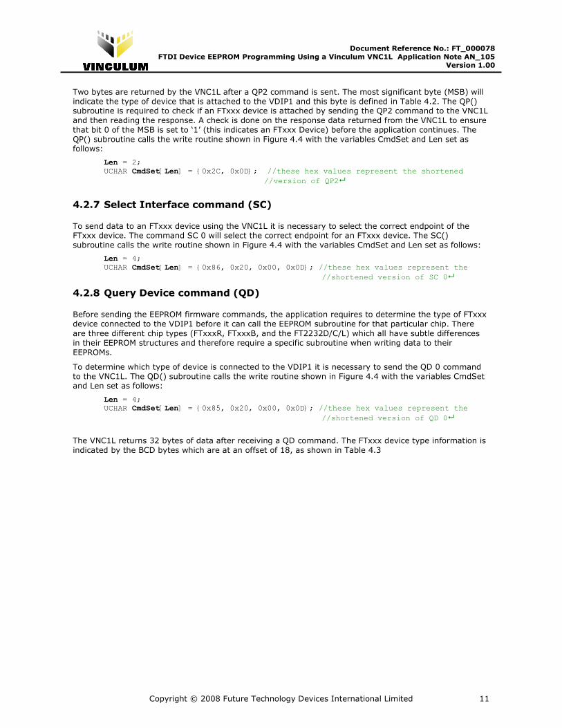
4.2.3 Write Firmware commands to VNC1L
The code structure in Figure 4.4 is used to write firmware commands to the VNC1L. The variables CmdSet and Len will change depending on the command that is sent. This fragment of code is referred to
throughout Section 4.2 using different variable values required for the appropiate firmware commands.
void WriteSubroutine(UCHAR CmdSet, DWORD Len) {
DWORD DataWritten; int WdataLen;
WriteDataLength = Len; DataWritten = 0; //Send command Status = FT_Write(FtHandle, &CmdSet, WriteDataLength, &DataWritten); if(Status != FT_OK) { printf("Write Failed\n"); ErrorStatus(); } Sleep(30); do { ReadByte(DataIn, &DataRead); //polling for prompt } while(DataRead = 0); }
Figure 4.4 Write Routine
To ensure that the VNC1L is responding correctly to the data sent by the PC a carriage return is transmitted to the VNC1L. A 0x0D is inserted into a data buffer and is written to the VNC1L. The VNC1L
should then respond with a prompt that is read in the ReadByte() subroutine. The carriage return is sent
to the VNC1L by using the write routine shown in Figure 4.4 with the variables CmdSet and Len set as follows:

Copyright © 2008 Future Technology Devices International Limited 10
Document Reference No.: FT_000078 FTDI Device EEPROM Programming Using a Vinculum VNC1L Application Note AN_105
Version 1.00 Clearance No.: FTDI# 59
Len = 1;
UCHAR CmdSet[Len] = {0x0D}; //these hex values ac carriage return �
4.2.4 Shortened Command Set command (SCS)
The shortened command set reduces the number of characters required to be sent to the VNC1L. A subroutine is set up in the application to switch from the monitors default extended command set (see
Table 4.1) to the shortened command set. In extended command set mode, printable characters are used
and commands are typically longer. In short command set mode, the commands are optimised for program control and they have binary values representing the command. The shortened command set
mode is set in the VNC1L by using the write routine shown in Figure 4.4 with the variables CmdSet and
Len set as follows:
Len = 2; UCHAR CmdSet[Len] = {0x10,0x0D}; //these hex values represent the shortened
//version of SCS�
4.2.5 Firmware Version command (FWV)
Since the EEPROM fimware commands are not present in fimrware versions earlier than 3.56, a
subroutine is configured to check the current version of firmware on the VNC1L. The firmware version FWV command returns a string that contains the firmware version that is on the VNC1L. The ReadByte()
command will read this string into a buffer and a string compare is done to make sure that the firmware
version is later that version 3.56. The FWV subroutine calls the write routine shown in Figure 4.4 with the variables CmdSet and Len set as follows:
Len = 2; UCHAR CmdSet[Len] = {0x13, 0x0D}; //these hex values represent the shortened
//version of FWV�
4.2.6 Query Port command (QP)
To check that an FTxxx device is attached to the VNC1L USB port 2 of the VDIP1 the Query Port 2 (QP2)
command is used. The QP2 command will return two bytes of information about the device that is connected into USB port 2 of the VDIP1.
Bit Device Type
7 Hub Device on Port
6 Unknown Device
5 BOMS Class Device
4 CDC Class Device
3 HID Class Device
2 Printer Class Device
1 Reserved (always 0)
0 FTDI FT232 / FT245 / FT2232 Device
Table 4.2 Device Type Bit Definition
Copyright © 2008 Future Technology Devices International Limited 11
Document Reference No.: FT_000078 FTDI Device EEPROM Programming Using a Vinculum VNC1L Application Note AN_105
Version 1.00 Clearance No.: FTDI# 59
Two bytes are returned by the VNC1L after a QP2 command is sent. The most significant byte (MSB) will
indicate the type of device that is attached to the VDIP1 and this byte is defined in Table 4.2. The QP() subroutine is required to check if an FTxxx device is attached by sending the QP2 command to the VNC1L
and then reading the response. A check is done on the response data returned from the VNC1L to ensure
that bit 0 of the MSB is set to ‘1’ (this indicates an FTxxx Device) before the application continues. The
QP() subroutine calls the write routine shown in Figure 4.4 with the variables CmdSet and Len set as follows:
Len = 2; UCHAR CmdSet[Len] = {0x2C, 0x0D}; //these hex values represent the shortened
//version of QP2�
4.2.7 Select Interface command (SC)
To send data to an FTxxx device using the VNC1L it is necessary to select the correct endpoint of the FTxxx device. The command SC 0 will select the correct endpoint for an FTxxx device. The SC()
subroutine calls the write routine shown in Figure 4.4 with the variables CmdSet and Len set as follows:
Len = 4; UCHAR CmdSet[Len] = {0x86, 0x20, 0x00, 0x0D}; //these hex values represent the
//shortened version of SC 0�
4.2.8 Query Device command (QD)
Before sending the EEPROM firmware commands, the application requires to determine the type of FTxxx
device connected to the VDIP1 before it can call the EEPROM subroutine for that particular chip. There
are three different chip types (FTxxxR, FTxxxB, and the FT2232D/C/L) which all have subtle differences
in their EEPROM structures and therefore require a specific subroutine when writing data to their
EEPROMs.
To determine which type of device is connected to the VDIP1 it is necessary to send the QD 0 command
to the VNC1L. The QD() subroutine calls the write routine shown in Figure 4.4 with the variables CmdSet and Len set as follows:
Len = 4; UCHAR CmdSet[Len] = {0x85, 0x20, 0x00, 0x0D}; //these hex values represent the
//shortened version of QD 0�
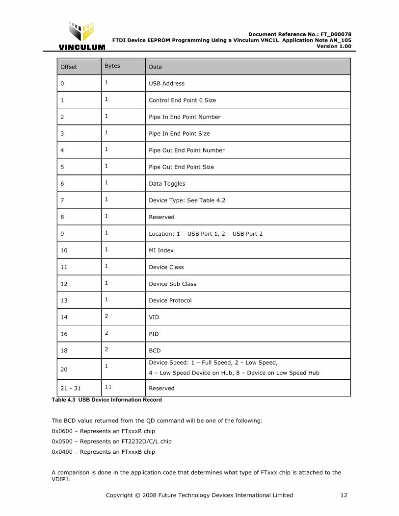
The VNC1L returns 32 bytes of data after receiving a QD command. The FTxxx device type information is
indicated by the BCD bytes which are at an offset of 18, as shown in Table 4.3
Copyright © 2008 Future Technology Devices International Limited 12
Document Reference No.: FT_000078 FTDI Device EEPROM Programming Using a Vinculum VNC1L Application Note AN_105
Version 1.00 Clearance No.: FTDI# 59
Offset Bytes Data
0 1 USB Address
1 1 Control End Point 0 Size
2 1 Pipe In End Point Number
3 1 Pipe In End Point Size
4 1 Pipe Out End Point Number
5 1 Pipe Out End Point Size
6 1 Data Toggles
7 1 Device Type: See Table 4.2
8 1 Reserved
9 1 Location: 1 – USB Port 1, 2 – USB Port 2
10 1 MI Index
11 1 Device Class
12 1 Device Sub Class
13 1 Device Protocol
14 2 VID
16 2 PID
18 2 BCD
20 1
Device Speed: 1 – Full Speed, 2 – Low Speed,
4 – Low Speed Device on Hub, 8 – Device on Low Speed Hub
21 - 31 11 Reserved
Table 4.3 USB Device Information Record
The BCD value returned from the QD command will be one of the following:
0x0600 – Represents an FTxxxR chip
0x0500 – Represents an FT2232D/C/L chip
0x0400 – Represents an FTxxxB chip
A comparison is done in the application code that determines what type of FTxxx chip is attached to the
VDIP1.
Copyright © 2008 Future Technology Devices International Limited 13
Document Reference No.: FT_000078 FTDI Device EEPROM Programming Using a Vinculum VNC1L Application Note AN_105
Version 1.00 Clearance No.: FTDI# 59
4.3 Subroutines for Reading and Writing to the EEPROM
When the VNC1L has been configured (see section 4.2), the application software can begin programming
the EEPROM of the attached FTxxx device. Sections 4.3.1 – 4.3.4 describe the methods used to configure
the VID, PID, serial number, manufacturer string and description string of the FTxxx device.
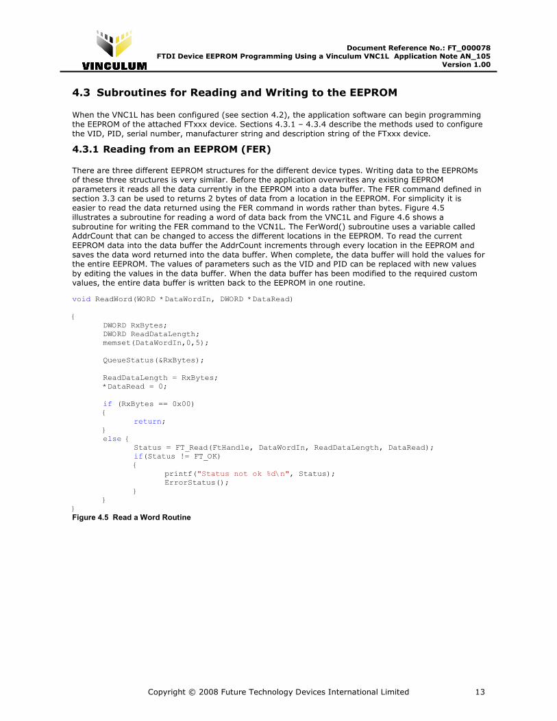
4.3.1 Reading from an EEPROM (FER)
There are three different EEPROM structures for the different device types. Writing data to the EEPROMs of these three structures is very similar. Before the application overwrites any existing EEPROM
parameters it reads all the data currently in the EEPROM into a data buffer. The FER command defined in section 3.3 can be used to returns 2 bytes of data from a location in the EEPROM. For simplicity it is
easier to read the data returned using the FER command in words rather than bytes. Figure 4.5
illustrates a subroutine for reading a word of data back from the VNC1L and Figure 4.6 shows a
subroutine for writing the FER command to the VCN1L. The FerWord() subroutine uses a variable called AddrCount that can be changed to access the different locations in the EEPROM. To read the current
EEPROM data into the data buffer the AddrCount increments through every location in the EEPROM and
saves the data word returned into the data buffer. When complete, the data buffer will hold the values for the entire EEPROM. The values of parameters such as the VID and PID can be replaced with new values
by editing the values in the data buffer. When the data buffer has been modified to the required custom values, the entire data buffer is written back to the EEPROM in one routine.
void ReadWord(WORD *DataWordIn, DWORD *DataRead) { DWORD RxBytes; DWORD ReadDataLength; memset(DataWordIn,0,5); QueueStatus(&RxBytes); ReadDataLength = RxBytes; *DataRead = 0; if (RxBytes == 0x00) { return; } else { Status = FT_Read(FtHandle, DataWordIn, ReadDataLength, DataRead); if(Status != FT_OK) { printf("Status not ok %d\n", Status); ErrorStatus(); } } }
Figure 4.5 Read a Word Routine
Copyright © 2008 Future Technology Devices International Limited 14
Document Reference No.: FT_000078 FTDI Device EEPROM Programming Using a Vinculum VNC1L Application Note AN_105
Version 1.00 Clearance No.: FTDI# 59
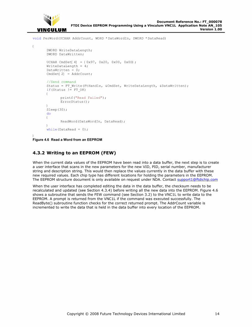
void FerWord(UCHAR AddrCount, WORD *DataWordIn, DWORD *DataRead) { DWORD WriteDataLength; DWORD DataWritten; UCHAR CmdSet[4] = {0x97, 0x20, 0x00, 0x0D}; WriteDataLength = 4; DataWritten = 0; CmdSet[2] = AddrCount; //Send command Status = FT_Write(FtHandle, &CmdSet, WriteDataLength, &DataWritten); if(Status != FT_OK) { printf("Read Failed"); ErrorStatus(); } Sleep(30); do { ReadWord(DataWordIn, DataRead); } while(DataRead = 0);
}
Figure 4.6 Read a Word from an EEPROM
4.3.2 Writing to an EEPROM (FEW)
When the current data values of the EEPROM have been read into a data buffer, the next step is to create
a user interface that scans in the new parameters for the new VID, PID, serial number, manufacturer
string and description string. This would then replace the values currently in the data buffer with these
new required values. Each chip type has different locations for holding the parameters in the EEPROM. The EEPROM structure document is only available on request under NDA. Contact [email protected]
When the user interface has completed editing the data in the data buffer, the checksum needs to be recalculated and updated (see Section 4.3.4) before writing all the new data into the EEPROM. Figure 4.6
shows a subroutine that sends the FEW command (see Section 3.2) to the VNC1L to write data to the EEPROM. A prompt is returned from the VNC1L if the command was executed successfully. The
ReadByte() subroutine function checks for the correct returned prompt. The AddrCount variable is incremented to write the data that is held in the data buffer into every location of the EEPROM.
Copyright © 2008 Future Technology Devices International Limited 15
Document Reference No.: FT_000078 FTDI Device EEPROM Programming Using a Vinculum VNC1L Application Note AN_105
Version 1.00 Clearance No.: FTDI# 59
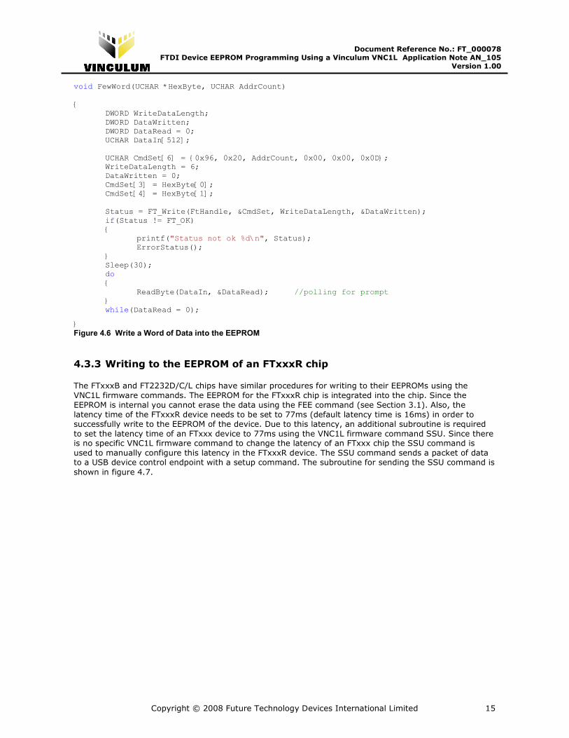
void FewWord(UCHAR *HexByte, UCHAR AddrCount) { DWORD WriteDataLength; DWORD DataWritten; DWORD DataRead = 0; UCHAR DataIn[512]; UCHAR CmdSet[6] = {0x96, 0x20, AddrCount, 0x00, 0x00, 0x0D}; WriteDataLength = 6; DataWritten = 0; CmdSet[3] = HexByte[0]; CmdSet[4] = HexByte[1]; Status = FT_Write(FtHandle, &CmdSet, WriteDataLength, &DataWritten); if(Status != FT_OK) { printf("Status not ok %d\n", Status); ErrorStatus(); } Sleep(30); do { ReadByte(DataIn, &DataRead); //polling for prompt } while(DataRead = 0);
}
Figure 4.6 Write a Word of Data into the EEPROM
4.3.3 Writing to the EEPROM of an FTxxxR chip
The FTxxxB and FT2232D/C/L chips have similar procedures for writing to their EEPROMs using the
VNC1L firmware commands. The EEPROM for the FTxxxR chip is integrated into the chip. Since the
EEPROM is internal you cannot erase the data using the FEE command (see Section 3.1). Also, the
latency time of the FTxxxR device needs to be set to 77ms (default latency time is 16ms) in order to successfully write to the EEPROM of the device. Due to this latency, an additional subroutine is required
to set the latency time of an FTxxx device to 77ms using the VNC1L firmware command SSU. Since there is no specific VNC1L firmware command to change the latency of an FTxxx chip the SSU command is
used to manually configure this latency in the FTxxxR device. The SSU command sends a packet of data to a USB device control endpoint with a setup command. The subroutine for sending the SSU command is
shown in figure 4.7.

Copyright © 2008 Future Technology Devices International Limited 16
Document Reference No.: FT_000078 FTDI Device EEPROM Programming Using a Vinculum VNC1L Application Note AN_105
Version 1.00 Clearance No.: FTDI# 59
void SSU() { DWORD WriteDataLength; DWORD DataWritten; DWORD DataRead = 0; UCHAR DataIn[512]; UCHAR CmdSet[11] = {0x9A, 0x20, 0x40, 0x09, 0x77, 0x00, 0x00, 0x00, 0x00, 0x00, 0x0D}; WriteDataLength = 11; DataWritten = 0; //Send command Status = FT_Write(FtHandle, &CmdSet, WriteDataLength, &DataWritten); if(Status != FT_OK) { printf("SC Command Failed\n"); ErrorStatus(); } Sleep(30); do { ReadByte(DataIn, &DataRead); //polling for prompt } while(DataRead = 0);
} Figure 4.7 SSU Command to Change the Latency to 77ms
When the latency has been configured, the internal EEPROM can be accessed using the FEW command. When writing to the EEPROM of FTxxxR devices, it is necessary to send data 2* 16 bit words (WORD1
and WORD2).
For example, Table 4.4 shows a segment of an example EEPROM map:
EEPROM Location Word Value (Hex)
00 $0101 (WORD 1)
01 $0101 (WORD 2)
02 $0101 (WORD 1)
03 $0101 (WORD 2)
04 $0101 (WORD 1)
05 $0101 (WORD 2)
Table 4.4 Example Segment of EEPROM Map Before a Write
Writing $FFFF to location 04 would require you to do the following:
In ASCII, Extended command set mode the command is:
LOC = 04 (WORD 1)
FEW·$(LOC)FFFF����
<prompt>

Copyright © 2008 Future Technology Devices International Limited 17
Document Reference No.: FT_000078 FTDI Device EEPROM Programming Using a Vinculum VNC1L Application Note AN_105
Version 1.00 Clearance No.: FTDI# 59
LOC = 05 (WORD 2)
FEW·$(LOC)0101���� //current data in location 05
<prompt>
Writing $FEFE to location 01 would require the following:
In ASCII, Extended command set mode the command is:
LOC = 00 (WORD 1)
FEW·$(LOC)0101���� //current data in location 06
<prompt>
LOC = 01 (WORD 2)
FEW·$(LOC)FEFE����
<prompt>
Table 4.5 shows the same EEPROM map after the FEW commands shown above are performed.
Location Word Value (Hex)
00 $0101 (WORD 1)
01 $FEFE (WORD 2) word has been changed
02 $0101 (WORD 1)
03 $0101 (WORD 2)
04 $FFFF (WORD 1) word has been changed
05 $0101 (WORD 2)
Table 4.5 Example Segment of EEPROM Map After a Write
Writing data to the EEPROM starting at the first location and finishing at the last location, the conditions
for writing two words at a time in order are met.
4.3.4 Checksum
Before all the data in the data buffer is written to the EEPROM the checksum needs to be updated and
stored in the EEPROM at the correct location. This is done by using the values in the data buffer to calculate and then store the checksum in the data buffer after the calculation is complete. This simplifies
the code by allowing the program to write all the data in the data buffer to the EEPROM in one routine instead of writing to the EEPROM twice (once to write the data and twice to write the checksum into the
EEPROM).
The details of how to calculate the checksum of the EEPROM are in EEPROM documents that are only
available by request under NDA. Contact [email protected]
Copyright © 2008 Future Technology Devices International Limited 18
Document Reference No.: FT_000078 FTDI Device EEPROM Programming Using a Vinculum VNC1L Application Note AN_105
Version 1.00 Clearance No.: FTDI# 59
5 Contact Information
Head Office – Glasgow, UK
Future Technology Devices International Limited
373 Scotland Street
Glasgow G5 8QB United Kingdom
Tel: +44 (0) 141 429 2777 Fax: +44 (0) 141 429 2758
E-mail (Sales) [email protected]
E-mail (Support) [email protected] E-mail (General Enquiries) [email protected]
Web Site URL http://www.ftdichip.com
Web Shop URL http://www.ftdichip.com
Branch Office – Taipei, Taiwan
Future Technology Devices International Limited (Taiwan)
4F, No 18-3, Sec. 6 Mincyuan East Road Neihu District
Taipei 114 Taiwan, R.O.C.
Tel: +886 (0) 2 8791 3570 Fax: +886 (0) 2 8791 3576
E-mail (Sales) [email protected]
E-mail (Support) [email protected]
E-mail (General Enquiries) [email protected]
Web Site URL http://www.ftdichip.com
Branch Office – Hillsboro, Oregon, USA
Future Technology Devices International Limited (USA) 7235 NW Evergreen Parkway, Suite 600
Hillsboro, OR 97123-5803 USA
Tel: +1 (503) 547 0988 Fax: +1 (503) 547 0987
E-Mail (Sales) [email protected]
E-Mail (Support) [email protected]
Web Site URL http://www.ftdichip.com
Distributor and Sales Representatives
Please visit the Sales Network page of the FTDI Web site for the contact details of our distributor(s) and sales representative(s) in your country.
Vinculum is part of Future Technology Devices International Ltd. Neither the whole nor any part of the information contained in, or the
product described in this manual, may be adapted or reproduced in any material or electronic form without the prior written consent of the copyright holder. This product and its documentation are supplied on an as-is basis and no warranty as to their suitability for any
particular purpose is either made or implied. Future Technology Devices International Ltd will not accept any claim for damages howsoever arising as a result of use or failure of this product. Your statutory rights are not affected. This product or any variant of it is
not intended for use in any medical appliance, device or system in which the failure of the product might reasonably be expected to result in personal injury. This document provides preliminary information that may be subject to change without notice. No freedom to
use patents or other intellectual property rights is implied by the publication of this document. Future Technology Devices International
Ltd, 373 Scotland Street, Glasgow G5 8QB United Kingdom. Scotland Registered Number: SC136640

Copyright © 2008 Future Technology Devices International Limited 19
Document Reference No.: FT_000078 FTDI Device EEPROM Programming Using a Vinculum VNC1L Application Note AN_105
Version 1.00 Clearance No.: FTDI# 59
Appendix A - References
Document Reference Description
VNC1L_MPROG_Application The code that this document is based on. Only available on
request under NDA. Contact [email protected]
DS_VNC1L-1A Vinculum Embedded USB Host Controller IC Data Sheet http://www.ftdichip.com
Vinculum Firmware User Manual Firmware user manual http://www.ftdichip.com
FTDI FT232 / FT245 / FT2232 FTDI FT232 / FT245 / FT2232 Data Sheet
http://www.ftdichip.com
BM_EEPROMdata_checksum-2.pdf EEPROM map for FT232 / FT245 ‘BM / ‘BL and ‘BQ devices.
Only available on request under NDA. Contact
FT2232 EEPROM Data Structure and Checksum.pdf
EEPROM map for FT2232D Only available on request under NDA. Contact
FT232REEPROM.pdf EEPROM map for FT232 / FT245 ‘RL / ‘RQ Only available on request under NDA. Contact
D2XX Programmer’s Guide D2XX Programmer’s Guide http://www.ftdichip.com
VDIP1 Data Sheet VDIP1 Data Sheet
http://www.ftdichip.com
Copyright © 2008 Future Technology Devices International Limited 20
Document Reference No.: FT_000078 FTDI Device EEPROM Programming Using a Vinculum VNC1L Application Note AN_105
Version 1.00 Clearance No.: FTDI# 59
Appendix B - Revision History
Revision History
Version 1.00 Initial Release September, 2008