Embed Size (px)
Citation preview
�
ENGLISH
INStructIoN MaNuaLaMS-224E / IP-410
* "compactFlash(tM)" is the registered trademark of SanDisk corporation, u.S.a.
�
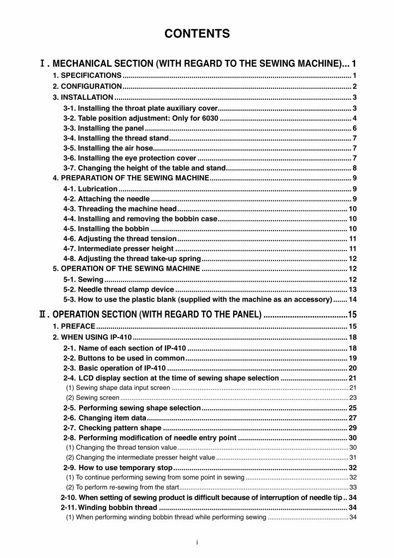
coNtENtS
!. MEcHaNIcaL SEctIoN (WItH rEGarD to tHE SEWING MacHINE)... 11. SPEcIFIcatIoNS ................................................................................................................. 12. coNFIGuratIoN ................................................................................................................. 23. INStaLLatIoN ..................................................................................................................... 3
3-1. Installing the throat plate auxiliary cover .................................................................. 3 3-2. table position adjustment: only for 6030 ................................................................. 4 3-3. Installing the panel ...................................................................................................... 6 3-4. Installing the thread stand .......................................................................................... 7 3-5. Installing the air hose .................................................................................................. 7 3-6. Installing the eye protection cover ............................................................................ 7 3-7. changing the height of the table and stand .............................................................. 8
4. PrEParatIoN oF tHE SEWING MacHINE ...................................................................... 9 4-1. Lubrication ................................................................................................................... 9 4-2. attaching the needle ................................................................................................... 9 4-3. threading the machine head .................................................................................... 10 4-4. Installing and removing the bobbin case ................................................................ 10 4-5. Installing the bobbin ................................................................................................. 10 4-6. adjusting the thread tension .................................................................................... 11 4-7. Intermediate presser height ..................................................................................... 11 4-8. adjusting the thread take-up spring ........................................................................ 12
5. oPEratIoN oF tHE SEWING MacHINE ........................................................................ 12 5-1. Sewing ........................................................................................................................ 12 5-2. Needle thread clamp device ..................................................................................... 13 5-3. How to use the plastic blank (supplied with the machine as an accessory) ....... 14
@. oPEratIoN SEctIoN (WItH rEGarD to tHE PaNEL) ......................................151. PrEFacE ............................................................................................................................ 152. WHEN uSING IP-410 .......................................................................................................... 18
2-1. Name of each section of IP-410 ............................................................................... 18 2-2. Buttons to be used in common ................................................................................ 19 2-3. Basic operation of IP-410 ......................................................................................... 20 2-4. LcD display section at the time of sewing shape selection ................................. 21
(1) Sew�ng shape data �nput screen ................................................................................................21(2) Sew�ng screen ............................................................................................................................23
2-5. Performing sewing shape selection ........................................................................ 25 2-6. changing item data ................................................................................................... 27 2-7. checking pattern shape ........................................................................................... 292-8.Performingmodificationofneedleentrypoint ...................................................... 30
(1) Chang�ng the thread tens�on value .............................................................................................30(2) Chang�ng the �ntermed�ate presser he�ght value ........................................................................31
2-9. How to use temporary stop ...................................................................................... 32(1) To cont�nue perform�ng sew�ng from some po�nt �n sew�ng ........................................................32(2) To perform re-sew�ng from the start ............................................................................................33
2-10.Whensettingofsewingproductisdifficultbecauseofinterruptionofneedletip .. 34 2-11. Winding bobbin thread ............................................................................................. 34
(1) When perform�ng w�nd�ng bobb�n thread wh�le perform�ng sew�ng ............................................34
��
(2) When perform�ng w�nd�ng bobb�n thread only ............................................................................35 2-12. using counter ............................................................................................................ 35
(1) Sett�ng procedure of the counter ................................................................................................35(2) Count-up releas�ng procedure ....................................................................................................37(3) How to change the counter value dur�ng sew�ng ........................................................................38
2-13. Performing new register of users’ pattern .............................................................. 38 2-14. Naming users’ pattern ............................................................................................... 39 2-15. Performing new register of pattern button ............................................................. 40 2-16. LcD display section at the time of pattern button selection ................................. 41
(1) Pattern button data �nput screen ................................................................................................41(2) Sew�ng screen ............................................................................................................................43
2-17. Performing pattern button No. selection ................................................................. 45(1) Select�on from the data �nput screen ..........................................................................................45(2) Select�on by means of the shortcut button .................................................................................46
2-18. changing contents of pattern button ...................................................................... 47 2-19. copying pattern button ............................................................................................. 48 2-20. changing sewing mode ............................................................................................ 49 2-21. LcD display section at the time of combination sewing ....................................... 50
(1) Pattern �nput screen ...................................................................................................................50(2) Sew�ng screen ............................................................................................................................52
2-22. Performing combination sewing .............................................................................. 54(1) Select�on of comb�nat�on data ....................................................................................................54(2) How to ed�t comb�nat�on data .....................................................................................................55(3) Delet�ng procedure of the comb�nat�on data ...............................................................................56(4) Delet�ng procedure of the step of the comb�nat�on data .............................................................56
2-23. changing memory switch data ................................................................................ 57 2-24. using information ...................................................................................................... 58
(1) Observ�ng the ma�ntenance and �nspect�on �nformat�on .............................................................58(2) Releas�ng procedure of the warn�ng ...........................................................................................59(3) Observ�ng the product�on control �nformat�on .............................................................................60(4) Perform�ng sett�ng of the product�on control �nformat�on ............................................................61(5) Observ�ng the work�ng measurement �nformat�on ......................................................................63
2-25. using communication function ................................................................................ 65(1) Handl�ng poss�ble data ...............................................................................................................65(2) Perform�ng commun�cat�on by us�ng the med�a ..........................................................................66(3) Perform�ng commun�cat�on by us�ng RS-232C ...........................................................................66(4) Take-�n of the data ......................................................................................................................66(5) Tak�ng �n plural data together......................................................................................................67
2-26. Performing formatting of the media ........................................................................ 69 2-27. operation at the time of X/Y motor position slip .................................................... 70
(1) When the error �s d�splayed dur�ng sew�ng .................................................................................70(2) When the error �s d�splayed after end of sew�ng ........................................................................71(3) When the rest sw�tch �s not d�splayed ........................................................................................71
2-28. uSING 2-StEP StroKE FuNctIoN ....................................................................... 72(1) Sett�ng of 2-step stroke funct�on .................................................................................................72(2) Sett�ng of 2-step stroke pos�t�on .................................................................................................72(3) Mot�on of 2-step stroke funct�on .................................................................................................74
3. MEMorY SWItcH Data LISt ........................................................................................... 76 3-1. Data list ....................................................................................................................... 76 3-2. Initial value list ........................................................................................................... 82
���
4. Error coDE LISt ............................................................................................................ 845. MESSaGE LISt .................................................................................................................. 91
#. MaINtENaNcE oF SaWING MacHINE ........................................... 941. MaINtENaNcE .................................................................................................................. 94
1-1. adjusting the height of the needle bar (changing the length of the needle) ...... 94 1-2. adjusting the needle-to-shuttle relation .................................................................. 94 1-3. adjusting the timing of main shaft and hook driving shaft .................................. 96 1-4. adjusting the height of the feeding frame .............................................................. 97 1-5. adjusting the vertical stroke of the intermediate presser ..................................... 97 1-6. the moving knife and counter knife ........................................................................ 98 1-7. Needle thread clamp device ..................................................................................... 98 1-8. thread breakage detector plate .............................................................................. 98 1-9. Draining waste oil ...................................................................................................... 99 1-10. amount of oil supplied to the hook ......................................................................... 99 1-11. replacing the fuse ..................................................................................................... 99 1-12. changing the voltage of 100,/200V ................................................................... 100 1-13. replenishing the designated places with grease ................................................. 101
(1) Replen�sh�ng the face plate sect�on (felt, �ntermed�ate presser l�nk, h�nge screw) w�th grease ...102(2) Replen�sh�ng the face plate sect�on (needle bar, �ntermed�ate presser bar, gu�de bar) w�th grease ..102
1-14. troubles and corrective measures (Sewing conditions) ..................................... 1032. oPtIoNaL ........................................................................................................................ 105
2-1. table of Needle hole guide ..................................................................................... 105 2-2. Silicon oil tank ........................................................................................................ 105
– 1 –
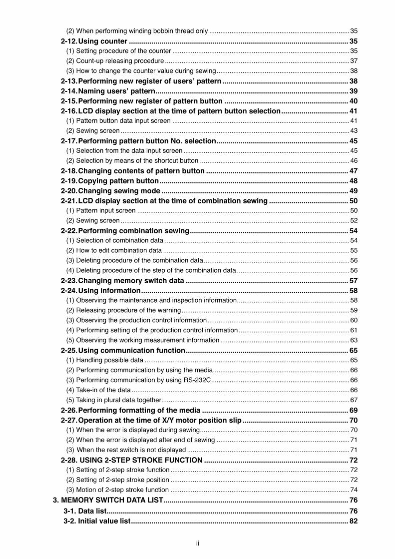
1. SPEcIFIcatIoNS
!. MEcHaNIcaL SEctIoN (WItH rEGarD to tHE SEWING MacHINE)
1 Sew�ng area X (lateral) d�rect�on Y (long�tud�nal) d�rect�on AMS-224E-4530 : 450 mm × 300 mmAMS-224E-6030 : 600 mm × 300 mm
2 Max. sew�ng speed 2,500 st�/m�n (When sew�ng p�tch �s 3 mm or less)3 Settable st�tch length 0.1 to 12.7 mm (M�n. resolut�on : 0.05 mm)4 Feed mot�on of feed�ng frame Interm�ttent feed (2-shaft dr�ve by stepp�ng motor)5 Needle bar stroke 41.2 mm6 Needle DP x 177 L�ft of feed�ng frame Max. 30mm8 Intermed�ate presser stroke 4 mm (Standard) (0 to 10 mm)9 L�ft of �ntermed�ate
presser20 mm
10 Intermed�ate presser DOWN pos�t�on var�able
Standard 0 to 3.5 mm (Max. 0 to 7.0 mm)
11 Shuttle Double-capac�ty sem�-rotary hook12 Lubr�cat�ng o�l New Defr�x O�l No. 2 (Suppl�ed by o�ler)13 Memory of pattern
data• Ma�n body : Max. 200 patterns (Max. 20,000 st�tches/pattern)• External med�a : Max. 999 patterns (Max. 50,000 st�tches/pattern)
14 Temporary stop fac�l�ty Used to stop mach�ne operat�on dur�ng a st�tch�ng cycle.15 Enlarg�ng / Reduc�ng
fac�l�tyAllows a pattern to be enlarged or reduced on the X ax�s and Y ax�s �ndependently when sew�ng a pattern. Scale : 1% to 400% t�mes (0.1% steps)
16 Enlarg�ng / Reduc�ng method
Pattern enlargement / reduct�on can be done by �ncreas�ng / decreas�ng e�ther st�tch length or the number of st�tches. (Increas�ng/decreas�ng st�tch length only can be performed when pattern button �s selected.)
17 Max. sew�ng speed l�m�tat�on
200 to 2,500 st�/m�n (Scale : 100 st�/m�n steps)
18 Pattern select�on fac�l�ty
Pattern No. select�on method
19 Bobb�n thread counter UP/DOWN method (0 to 9,999)20 Sew�ng counter UP/DOWN method (0 to 9,999) 21 Memory back-up In case of a power �nterrupt�on, the pattern be�ng used w�ll automat�cally be stored �n
memory.22 2nd or�g�n sett�ng
fac�l�tyUs�ng jog keys, a 2nd or�g�n (needle pos�t�on after a sew�ng cycle) can be set �n the des�red pos�t�on w�th�n the sew�ng area. The set 2nd or�g�n �s also stored �n memory.
23 Sew�ng mach�ne motor Servo-motor24 D�mens�ons AMS-224E-4530 : 1,703mm (W) x 1,370mm (L) x 1,200mm (H) (Exclud�ng thread stand)
AMS-224E-6030 : 1,923mm (W) x 1,370mm (L) x 1,200mm (H) (Exclud�ng thread stand)25 Mass (gross mass) AMS-224E-4530 : 401 kg
AMS-224E-6030 : 410 kg26 Power consumpt�on 550 VA 27 Operat�ng temperature
range5˚C to 35˚C
28 Operat�ng hum�d�ty range 35 % to 85 % (No dew condensat�on)29 L�ne voltage Rated voltage ±10% 50 / 60 Hz30 A�r pressure used AMS-224E-4530 : 0.5 to 0.55 MPa (Max. 0.55 MPa)
AMS-224E-6030 : 0.5 to 0.55 MPa (Max. 0.55 MPa)31 A�r consumpt�on 1.8 dm3 / m�n (ANR)32 Needle h�ghest
pos�t�on stop fac�l�tyAfter the complet�on of sew�ng, the needle can be brought up to �ts h�ghest pos�t�on.
33 No�se '- Equ�valent cont�nuous em�ss�on sound pressure level (LpA) at the workstat�on : A-we�ghted value of 83.5 dB ; (Includes KpA = 2.5 dB) ; accord�ng to ISO 10821- C.6.3 -ISO 11204 GR2 at 2500 st�/m�n.
'- Sound power level (LWA) : A-we�ghted value of 92.5 dB ; (Includes KpA = 2.5 dB) ; accord�ng to ISO 10821- C.6.3 -ISO 11204 GR2 at 2500 st�/m�n.
– 2 –
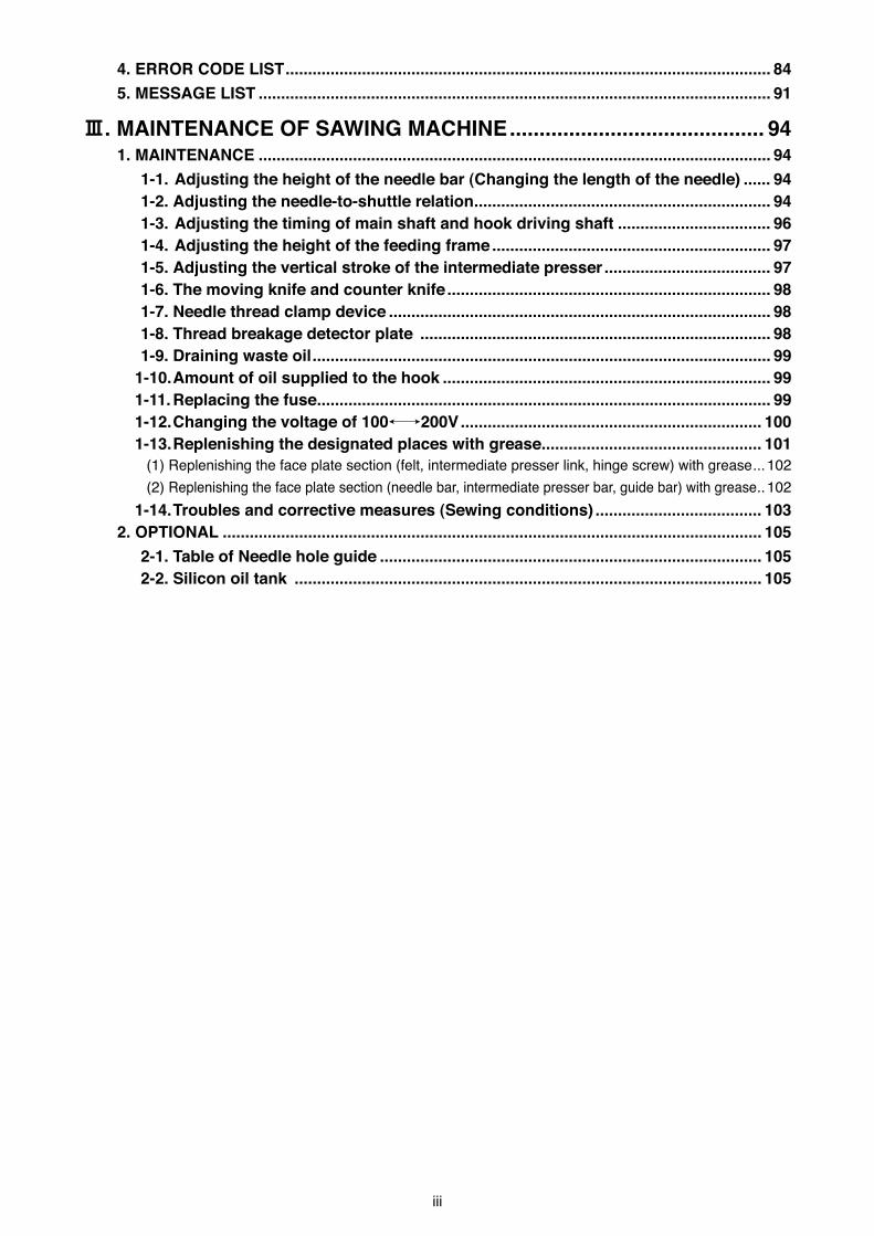
A�r regulator
2. coNFIGuratIoN
1 Mach�ne head2 W�per sw�tch3 Temporary stop sw�tch4 Feed�ng frame5 Intermed�ate presser6 Thread stand7 Operat�on panel (IP-410)8 Power sw�tch 9 Control box!0 Foot pedal
12
3
4
6
7
9
!0
5
8
– 3 –
3. INStaLLatIoN
3-1. Installing the throat plate auxiliary cover
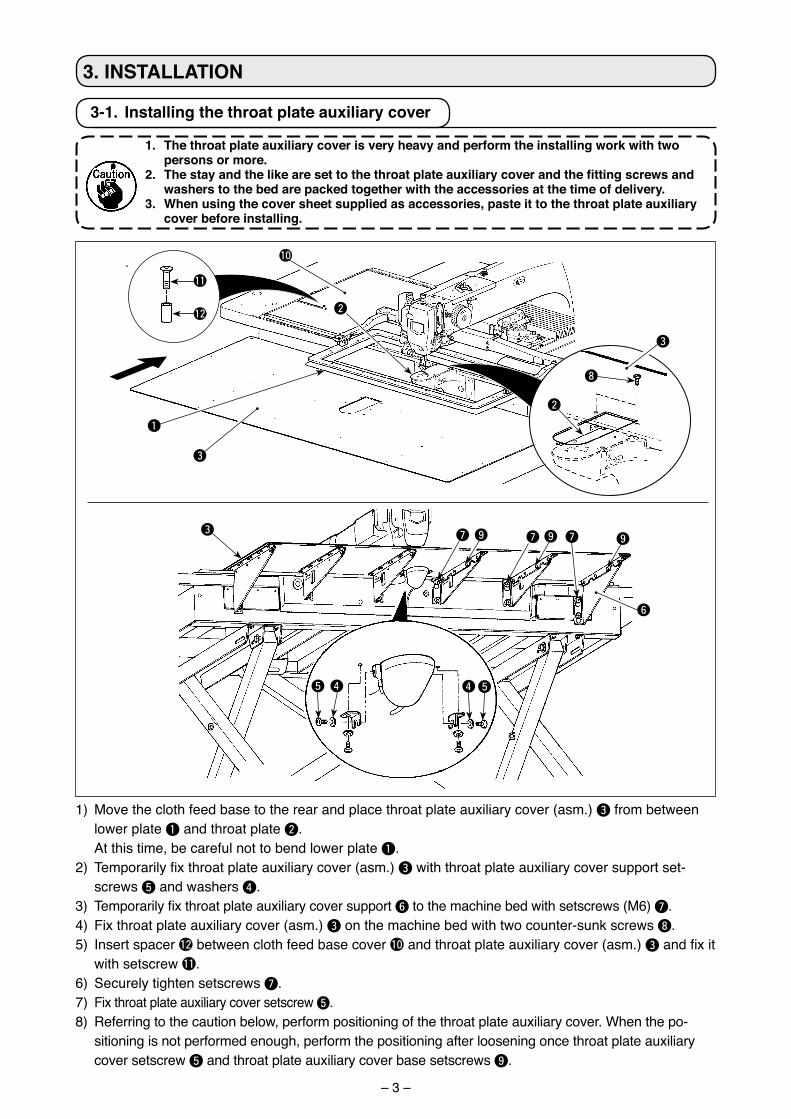
1. the throat plate auxiliary cover is very heavy and perform the installing work with two persons or more.
2.Thestayandthelikearesettothethroatplateauxiliarycoverandthefittingscrewsandwashers to the bed are packed together with the accessories at the time of delivery.
3. When using the cover sheet supplied as accessories, paste it to the throat plate auxiliary cover before installing.
1) Move the cloth feed base to the rear and place throat plate aux�l�ary cover (asm.) 3 from between lower plate 1 and throat plate 2.
At th�s t�me, be careful not to bend lower plate 1.2) Temporarily fix throat plate auxiliary cover (asm.) 3 w�th throat plate aux�l�ary cover support set-
screws 5 and washers 4.3) Temporarily fix throat plate auxiliary cover support 6 to the mach�ne bed w�th setscrews (M6) 7.4) F�x throat plate aux�l�ary cover (asm.) 3 on the mach�ne bed w�th two counter-sunk screws 8.5) Insert spacer !2 between cloth feed base cover !0 and throat plate aux�l�ary cover (asm.) 3 and fix it
w�th setscrew !1.6) Securely t�ghten setscrews 7.7) F�x throat plate aux�l�ary cover setscrew 5.8) Referr�ng to the caut�on below, perform pos�t�on�ng of the throat plate aux�l�ary cover. When the po-
s�t�on�ng �s not performed enough, perform the pos�t�on�ng after loosen�ng once throat plate aux�l�ary cover setscrew 5 and throat plate aux�l�ary cover base setscrews 9.
3
2
1
!0
8
3
2
!1
!2
45
3
6
7
45
7 79 9 9
– 4 –
Within 0.3 mm
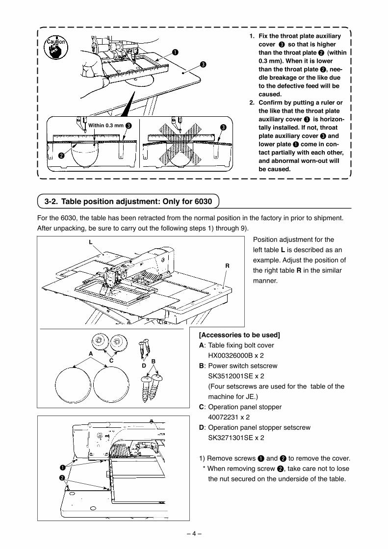
1. Fix the throat plate auxiliary cover 3 so that is higher than the throat plate 2 (within 0.3 mm). When it is lower than the throat plate 2, nee-dle breakage or the like due to the defective feed will be caused.
2.Confirmbyputtingarulerorthe like that the throat plate auxiliary cover 3 is horizon-tally installed. If not, throat plate auxiliary cover 3 and lower plate 1 come in con-tact partially with each other, and abnormal worn-out will be caused.
3
3
2
3
1
L
1
2
r
aBc
D
3-2. table position adjustment: only for 6030
For the 6030, the table has been retracted from the normal pos�t�on �n the factory �n pr�or to sh�pment.After unpack�ng, be sure to carry out the follow�ng steps 1) through 9).
Pos�t�on adjustment for the left table L �s descr�bed as an example. Adjust the pos�t�on of the r�ght table r �n the s�m�lar manner.
[accessories to be used]a: Table fixing bolt cover HX00326000B x 2B: Power sw�tch setscrew SK3512001SE x 2 (Four setscrews are used for the table of the
mach�ne for JE.)c: Operat�on panel stopper 40072231 x 2D: Operat�on panel stopper setscrew SK3271301SE x 2
1) Remove screws 1 and 2 to remove the cover. * When remov�ng screw 2, take care not to lose
the nut secured on the unders�de of the table.
– 5 –
175mm
3
1
2
a
B B
c, D
Power switch for the domestic market and general export
Power switch for JE
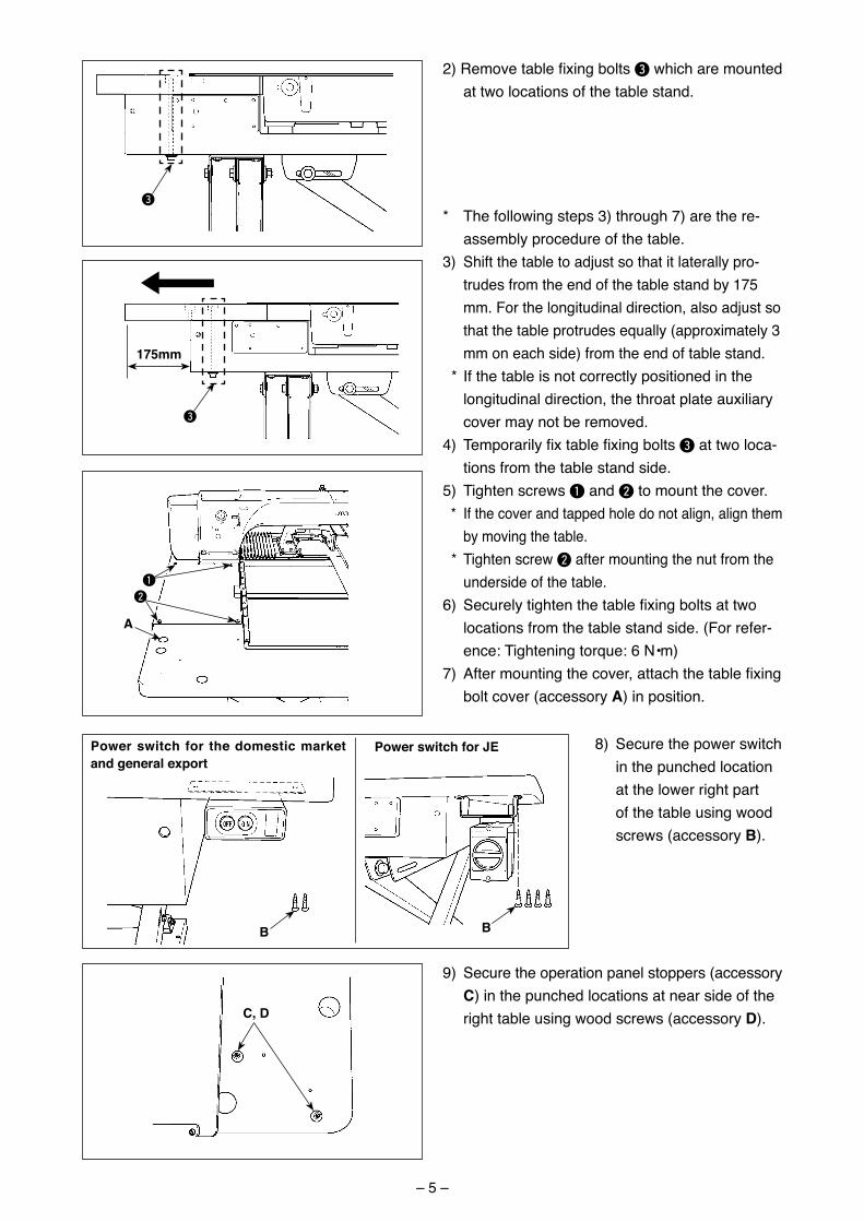
* The follow�ng steps 3) through 7) are the re-assembly procedure of the table.
3) Sh�ft the table to adjust so that �t laterally pro-trudes from the end of the table stand by 175 mm. For the long�tud�nal d�rect�on, also adjust so that the table protrudes equally (approx�mately 3 mm on each s�de) from the end of table stand.
* If the table �s not correctly pos�t�oned �n the long�tud�nal d�rect�on, the throat plate aux�l�ary cover may not be removed.
4) Temporarily fix table fixing bolts 3 at two loca-t�ons from the table stand s�de.
5) T�ghten screws 1 and 2 to mount the cover. * If the cover and tapped hole do not al�gn, al�gn them
by mov�ng the table. * T�ghten screw 2 after mount�ng the nut from the
unders�de of the table. 6) Securely tighten the table fixing bolts at two
locat�ons from the table stand s�de. (For refer-ence: T�ghten�ng torque: 6 N•m)
7) After mounting the cover, attach the table fixing bolt cover (accessory a) �n pos�t�on.
9) Secure the operat�on panel stoppers (accessory c) �n the punched locat�ons at near s�de of the r�ght table us�ng wood screws (accessory D).
8) Secure the power sw�tch �n the punched locat�on at the lower r�ght part of the table us�ng wood screws (accessory B).
3
2) Remove table fixing bolts 3 wh�ch are mounted at two locat�ons of the table stand.
– 6 –
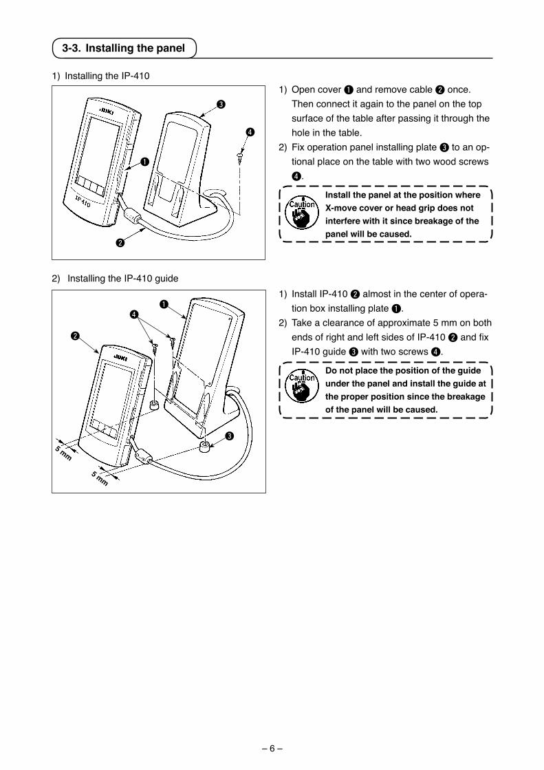
3-3. Installing the panel
1) Open cover 1 and remove cable 2 once. Then connect �t aga�n to the panel on the top surface of the table after pass�ng �t through the hole �n the table.
2) F�x operat�on panel �nstall�ng plate 3 to an op-t�onal place on the table w�th two wood screws 4.
Install the panel at the position where X-move cover or head grip does not interfere with it since breakage of the panel will be caused.
1) Install�ng the IP-410
2) Install�ng the IP-410 gu�de
4
3
1
2
1
2
3
5 mm
5 mm
1) Install IP-410 2 almost �n the center of opera-t�on box �nstall�ng plate 1.
2) Take a clearance of approx�mate 5 mm on both ends of r�ght and left s�des of IP-410 2 and fix IP-410 gu�de 3 w�th two screws 4.
Do not place the position of the guide under the panel and install the guide at the proper position since the breakage of the panel will be caused.
4
– 7 –
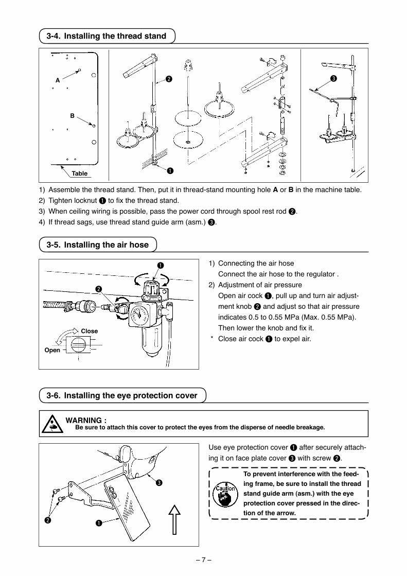
3-4. Installing the thread stand
1) Assemble the thread stand. Then, put �t �n thread-stand mount�ng hole a or B �n the mach�ne table.2) T�ghten locknut 1 to fix the thread stand.3) When ce�l�ng w�r�ng �s poss�ble, pass the power cord through spool rest rod 2.4) If thread sags, use thread stand gu�de arm (asm.) 3.
3-5. Installing the air hose
close
open
1) Connect�ng the a�r hose Connect the a�r hose to the regulator .2) Adjustment of a�r pressure Open a�r cock 1, pull up and turn a�r adjust-
ment knob 2 and adjust so that a�r pressure �nd�cates 0.5 to 0.55 MPa (Max. 0.55 MPa). Then lower the knob and fix it.
* Close a�r cock 1 to expel a�r.
3-6. Installing the eye protection cover
WarNING : Be sure to attach this cover to protect the eyes from the disperse of needle breakage.
Use eye protect�on cover 1 after securely attach-�ng �t on face plate cover 3 w�th screw 2.
to prevent interference with the feed-ing frame, be sure to install the thread stand guide arm (asm.) with the eye protection cover pressed in the direc-tion of the arrow.
1
3
2
1
2 3a
B
1
2
⇧
table
– 8 –
aa
1
2
3
4
5
67
8
9
!0
!1
!5
!2
!8
!4
!3
!6
!7
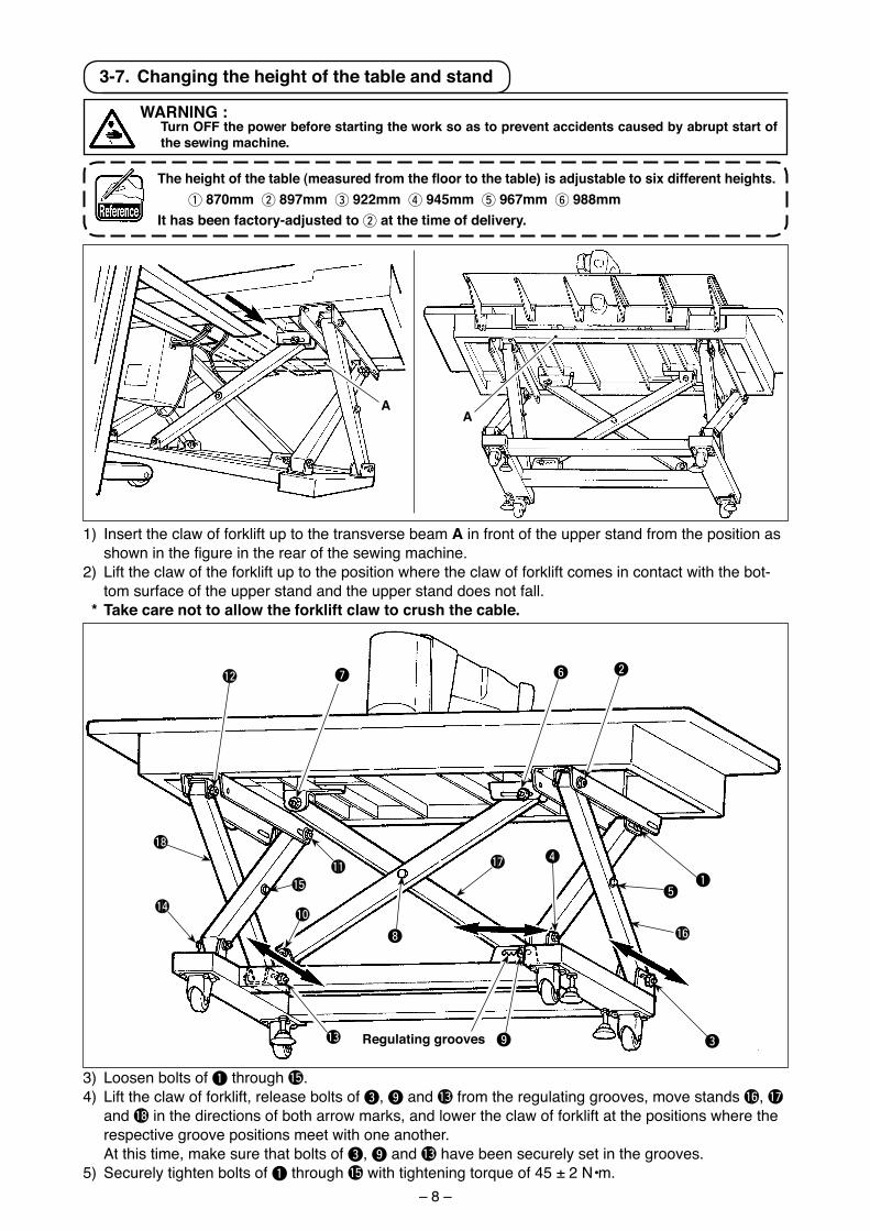
3) Loosen bolts of 1 through !5.4) L�ft the claw of forkl�ft, release bolts of 3, 9 and !3 from the regulat�ng grooves, move stands !6, !7
and !8 �n the d�rect�ons of both arrow marks, and lower the claw of forkl�ft at the pos�t�ons where the respect�ve groove pos�t�ons meet w�th one another.
At th�s t�me, make sure that bolts of 3, 9 and !3 have been securely set �n the grooves.5) Securely t�ghten bolts of 1 through !5 w�th t�ghten�ng torque of 45 ± 2 N•m.
3-7. changing the height of the table and stand
1) Insert the claw of forkl�ft up to the transverse beam a �n front of the upper stand from the pos�t�on as shown in the figure in the rear of the sewing machine.
2) L�ft the claw of the forkl�ft up to the pos�t�on where the claw of forkl�ft comes �n contact w�th the bot-tom surface of the upper stand and the upper stand does not fall.
* take care not to allow the forklift claw to crush the cable.
regulating grooves
WarNING : turn oFF the power before starting the work so as to prevent accidents caused by abrupt start of
the sewing machine.
Theheightofthetable(measuredfromthefloortothetable)isadjustabletosixdifferentheights. 1 870mm 2 897mm 3 922mm 4 945mm 5 967mm 6 988mmIt has been factory-adjusted to 2 at the time of delivery.
– 9 –
4. PrEParatIoN oF tHE SEWING MacHINE
4-1. Lubrication
WarNING : turn oFF the power before starting the work so as to prevent accidents caused by abrupt start of
the sewing machine.
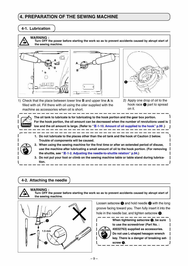
1) Check that the place between lower l�ne B and upper l�ne a �s filled with oil. Fill there with oil using the oiler supplied with the mach�ne as accessor�es when o�l �s short.
1. Do not lubricate to the places other than the oil tank and the hook of caution 2 below. trouble of components will be caused.
2. Whenusingthesewingmachineforthefirsttimeorafteranextendedperiodofdisuse,use the machine after lubricating a small amount of oil to the hook portion. (For removing the shuttle, see “#-1-2. adjusting the needle-to-shuttle relation” p.94.)
3. Do not put your foot or climb on the sewing machine table or table stand during lubrica-tion.
2) Apply one drop of o�l to the hook race 1 part to spread on �t.
the oil tank to lubricate is for lubricating to the hook portion and the gear box portion.For the hook portion, the oil amount can be decreased when the number of revolutions used is low and the oil amount is large. (refer to “#-1-10. amount of oil supplied to the hook” p.99 .)
4-2. attaching the needle
1
2
WarNING : turn oFF the power before starting the work so as to prevent accidents caused by abrupt start of
the sewing machine.
Loosen setscrew 1 and hold needle 2 w�th the long groove fac�ng toward you. Then fully �nsert �t �nto the hole �n the needle bar, and t�ghten setscrew 1.
When tightening setscrew 1, be sure to use the screwdriver (Part No. : 40032763) supplied as accessories.Do not use L-shaped hexagon wrench key. there is a danger of breaking set-screw 1.
1.5 mm
1
a
Ba
B
– 10 –
4-3. threading the machine head
WarNING : turn oFF the power before starting the work so as to prevent accidents caused by abrupt start of
the sewing machine.
4-4. Installing and removing the bobbin case
WarNING : turn oFF the power before starting the work so as to prevent accidents caused by abrupt start of
the sewing machine.
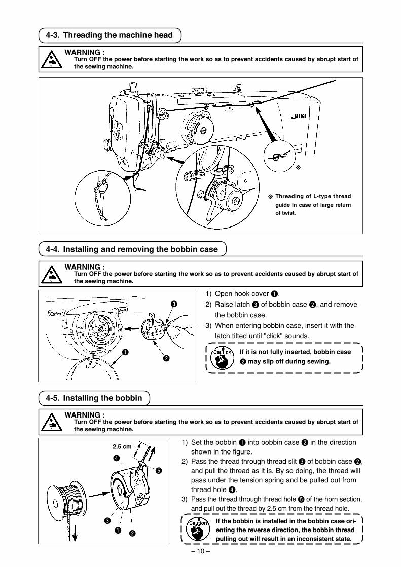
1) Open hook cover 1.2) Ra�se latch 3 of bobb�n case 2, and remove
the bobb�n case.3) When enter�ng bobb�n case, �nsert �t w�th the
latch t�lted unt�l "cl�ck" sounds.
If it is not fully inserted, bobbin case 2 may slip off during sewing.
1
3
2
※
※ threading of L-type thread guide in case of large return of twist.
4-5. Installing the bobbin
WarNING : turn oFF the power before starting the work so as to prevent accidents caused by abrupt start of
the sewing machine.
1) Set the bobb�n 1 �nto bobb�n case 2 �n the d�rect�on shown in the figure.
2) Pass the thread through thread sl�t 3 of bobb�n case 2, and pull the thread as �t �s. By so do�ng, the thread w�ll pass under the tens�on spr�ng and be pulled out from thread hole 4.
3) Pass the thread through thread hole 5 of the horn sect�on, and pull out the thread by 2.5 cm from the thread hole.
If the bobbin is installed in the bobbin case ori-enting the reverse direction, the bobbin thread pulling out will result in an inconsistent state.
5
4
1 2
3
2.5 cm
– 11 –
2
1
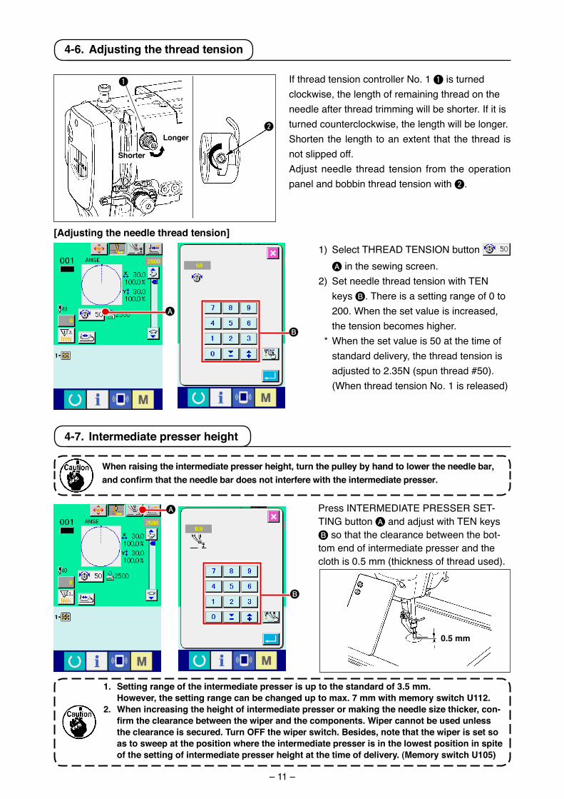
4-6. adjusting the thread tension
If thread tens�on controller No. 1 1 �s turned clockw�se, the length of rema�n�ng thread on the needle after thread tr�mm�ng w�ll be shorter. If �t �s turned counterclockw�se, the length w�ll be longer.Shorten the length to an extent that the thread �s not sl�pped off.Adjust needle thread tens�on from the operat�on panel and bobb�n thread tens�on w�th 2.
Longer
Shorter
[adjusting the needle thread tension]1) Select THREAD TENSION button
A �n the sew�ng screen.2) Set needle thread tens�on w�th TEN
keys B. There �s a sett�ng range of 0 to 200. When the set value �s �ncreased, the tens�on becomes h�gher.
* When the set value �s 50 at the t�me of standard del�very, the thread tens�on �s adjusted to 2.35N (spun thread #50). (When thread tens�on No. 1 �s released)
B
A
4-7. Intermediate presser height
Press INTERMEDIATE PRESSER SET-TING button A and adjust w�th TEN keys B so that the clearance between the bot-tom end of �ntermed�ate presser and the cloth �s 0.5 mm (th�ckness of thread used).
1. Setting range of the intermediate presser is up to the standard of 3.5 mm. However, the setting range can be changed up to max. 7 mm with memory switch u112. 2. When increasing the height of intermediate presser or making the needle size thicker, con-
firmtheclearancebetweenthewiperandthecomponents.Wipercannotbeusedunlessthe clearance is secured. turn oFF the wiper switch. Besides, note that the wiper is set so as to sweep at the position where the intermediate presser is in the lowest position in spite of the setting of intermediate presser height at the time of delivery. (Memory switch u105)
When raising the intermediate presser height, turn the pulley by hand to lower the needle bar, andconfirmthattheneedlebardoesnotinterferewiththeintermediatepresser.
0.5 mm
B
A
– 12 –
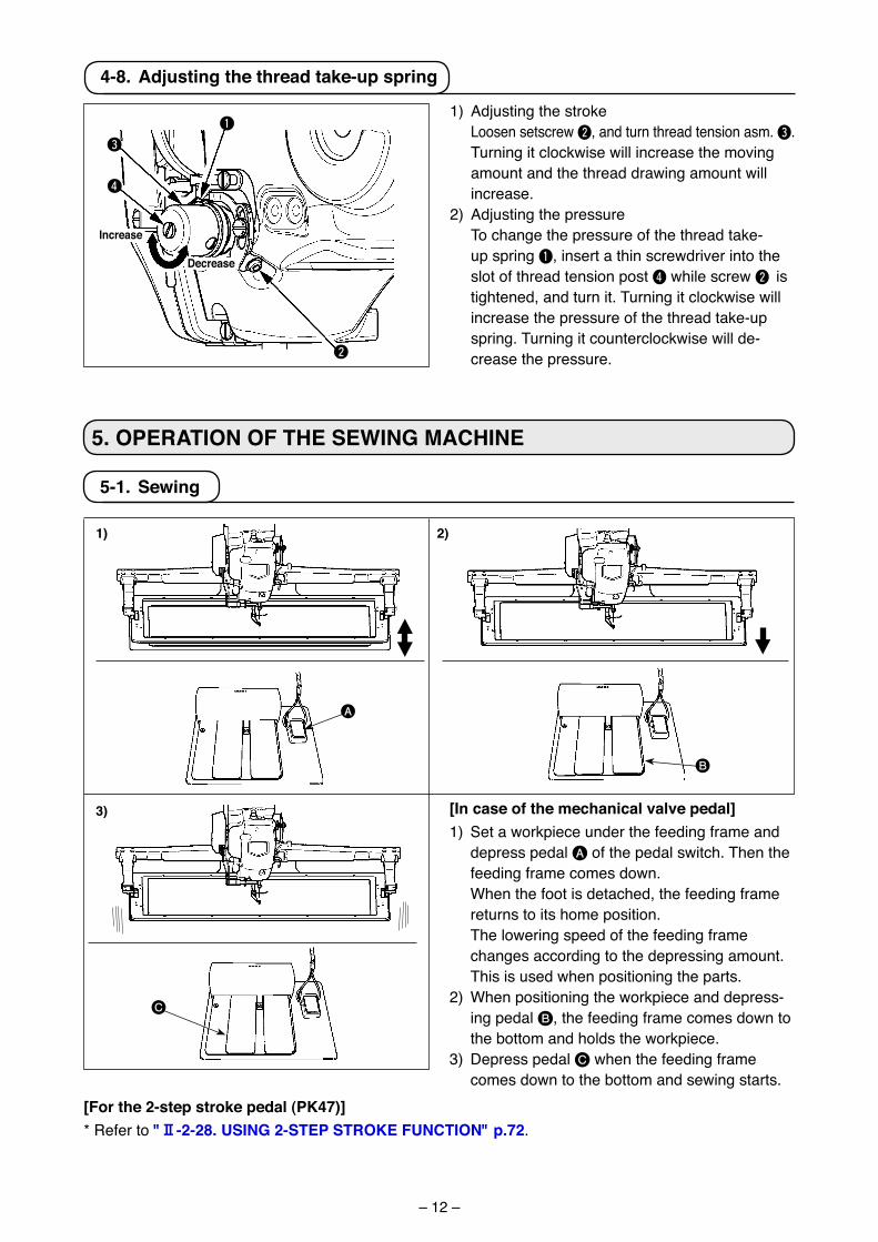
4-8. adjusting the thread take-up spring
3
2
1
4
1) Adjust�ng the stroke Loosen setscrew 2, and turn thread tens�on asm. 3. Turn�ng �t clockw�se w�ll �ncrease the mov�ng
amount and the thread draw�ng amount w�ll �ncrease.
2) Adjust�ng the pressure To change the pressure of the thread take-
up spr�ng 1, �nsert a th�n screwdr�ver �nto the slot of thread tens�on post 4 wh�le screw 2 �s t�ghtened, and turn �t. Turn�ng �t clockw�se w�ll �ncrease the pressure of the thread take-up spr�ng. Turn�ng �t counterclockw�se w�ll de-crease the pressure.
Decrease
Increase
5. oPEratIoN oF tHE SEWING MacHINE
A
B
C
1) 2)
3)
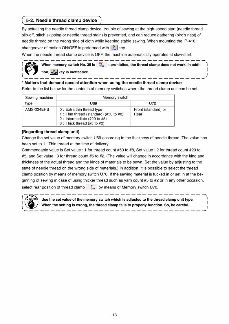
5-1. Sewing
[In case of the mechanical valve pedal]1) Set a workp�ece under the feed�ng frame and
depress pedal A of the pedal sw�tch. Then the feed�ng frame comes down.
When the foot �s detached, the feed�ng frame returns to �ts home pos�t�on.
The lower�ng speed of the feed�ng frame changes accord�ng to the depress�ng amount.
Th�s �s used when pos�t�on�ng the parts.2) When pos�t�on�ng the workp�ece and depress-
�ng pedal B, the feed�ng frame comes down to the bottom and holds the workp�ece.
3) Depress pedal C when the feed�ng frame comes down to the bottom and sew�ng starts.
[For the 2-step stroke pedal (PK47)]* Refer to "@-2-28. uSING 2-StEP StroKE FuNctIoN" p.72.
– 13 –
5-2. Needle thread clamp device
By actuat�ng the needle thread clamp dev�ce, trouble of sew�ng at the h�gh-speed start (needle thread sl�p-off, st�tch sk�pp�ng or needle thread sta�n) �s prevented, and can reduce gather�ng (b�rd's nest) of needle thread on the wrong s�de of cloth wh�le keep�ng stable sew�ng. When mount�ng the IP-410, changeover of mot�on ON/OFF �s performed w�th key.When the needle thread clamp dev�ce �s OFF, the mach�ne automat�cally operates at slow-start.
When memory switch No. 35 is : prohibited, the thread clamp does not work. In addi-
tion, key is ineffective.
* Matters that demand special attention when using the needle thread clamp deviceRefer to the l�st below for the contents of memory sw�tches where the thread clamp un�t can be set.
Sew�ng mach�ne type
Memory sw�tchU69 U70
AMS-224EHS 0 : Extra th�n thread type1 : Th�n thread (standard) (#50 to #8)2 : Intermed�ate (#20 to #5)3 : Th�ck thread (#5 to #2)
Front (standard) orRear
[regarding thread clamp unit]Change the set value of memory sw�tch U69 accord�ng to the th�ckness of needle thread. The value has been set to 1 : Th�n thread at the t�me of del�very.Commendable value �s Set value : 1 for thread count #50 to #8, Set value : 2 for thread count #20 to #5, and Set value : 3 for thread count #5 to #2. (The value w�ll change �n accordance w�th the k�nd and th�ckness of the actual thread and the k�nds of mater�als to be sewn. Set the value by adjust�ng to the state of needle thread on the wrong s�de of mater�als.) In add�t�on, �t �s poss�ble to select the thread clamp pos�t�on by means of memory sw�tch U70. If the sew�ng mater�al �s tucked �n or set �n at the be-g�nn�ng of sew�ng �n case of us�ng th�cker thread such as yarn count #5 to #2 or �n any other occas�on, select rear pos�t�on of thread clamp by means of Memory sw�tch U70.
use the set value of the memory switch which is adjusted to the thread clamp unit type. When the setting is wrong, the thread clamp fails to properly function. So, be careful.
– 14 –
(2) When the thread clamp �s used, and bobb�n thread at the sew�ng start appears on the r�ght s�de of mater�al, reduce thread tens�on at the sew�ng start (2 to 3 st�tches) and bobb�n thread becomes less consp�cuous.
[Example of setting] Tens�on of 1 to 2 st�tches at the sew�ng start �s “20” when sew�ng tens�on sett�ng �s “35”. * For sett�ng of tens�on at the start of sew�ng, see of "@-2-8.(1) changing the thread tension value" p.30.
1. thread at the start of sewing may be rolled in case of some patterns. When thread is rolled in even after performing adjustment of (1) or (2), use the sewing machine with thread clamp oFF.
2. thread clamp failure may occur in the state that thread waste is jammed in the thread clamp device. remove the thread waste referring to
"#-1-7. Needle thread clamp device" p.98.
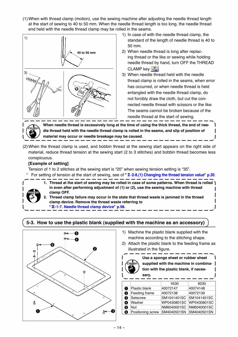
5-3. How to use the plastic blank (supplied with the machine as an accessory)
1) Mach�ne the plast�c blank suppl�ed w�th the mach�ne accord�ng to the st�tch�ng shape.
2) Attach the plast�c blank to the feed�ng frame as illustrated in the figure.
use a sponge sheet or rubber sheet supplied with the machine in combina-tion with the plastic blank, if neces-sary.
4530 60301 Plast�c blank 40072147 400741482 Feed�ng frame 40072138 400721393 Setscrew SM1041401SC SM1041401SC4 Washer WP0430801SC WP0430801SC5 Nut NM6040001SC NM6040001SC6 Pos�t�on�ng screw SM4040501SN SM4040501SN
5
4
2
1
6
3
When needle thread is excessively long at the time of using the thick thread, the end of nee-dle thread held with the needle thread clamp is rolled in the seams, and slip of position of material may occur or needle breakage may be caused.
(1) When w�th thread clamp (mot�on), use the sew�ng mach�ne after adjust�ng the needle thread length at the start of sew�ng to 40 to 50 mm. When the needle thread length �s too long, the needle thread end held w�th the needle thread clamp may be rolled �n the seams.
40 to 50 mm
1) In case of w�th the needle thread clamp, the standard of the length of needle thread �s 40 to 50 mm.
2) When needle thread �s long after replac-�ng thread or the l�ke or sew�ng wh�le hold�ng needle thread by hand, turn OFF the THREAD CLAMP key .
3) When needle thread held w�th the needle thread clamp �s rolled �n the seams, when error has occurred, or when needle thread �s held entangled w�th the needle thread clamp, do not forc�bly draw the cloth, but cut the con-nected needle thread w�th sc�ssors or the l�ke. The seams cannot be broken because of the needle thread at the start of sew�ng.
1)
3)
– 15 –
1. PrEFacE
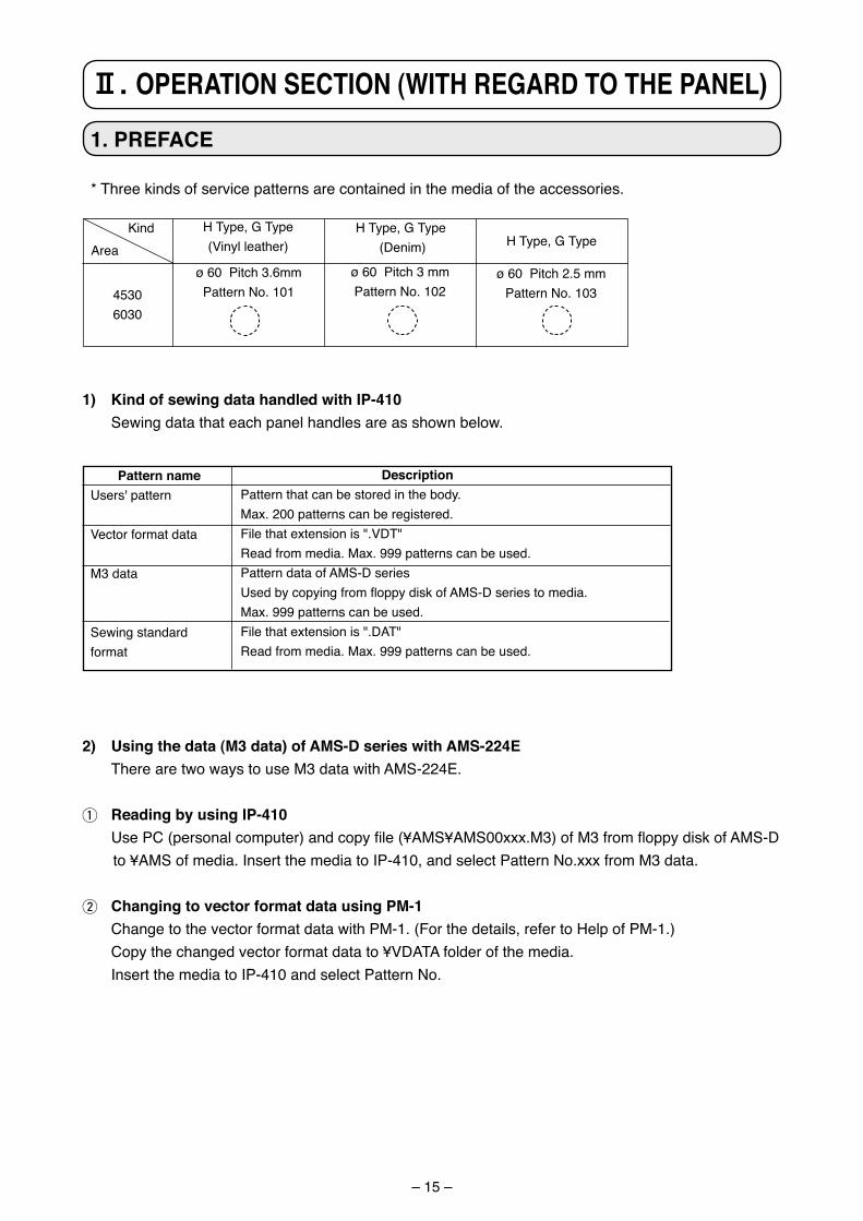
* Three k�nds of serv�ce patterns are conta�ned �n the med�a of the accessor�es.
1) Kind of sewing data handled with IP-410 Sew�ng data that each panel handles are as shown below.
Pattern nameUsers' pattern
Vector format data
M3 data
Sew�ng standard format
DescriptionPattern that can be stored �n the body.Max. 200 patterns can be reg�stered.F�le that extens�on �s ".VDT"Read from med�a. Max. 999 patterns can be used.Pattern data of AMS-D ser�esUsed by copying from floppy disk of AMS-D series to media. Max. 999 patterns can be used.F�le that extens�on �s ".DAT"Read from med�a. Max. 999 patterns can be used.
2) using the data (M3 data) of aMS-D series with aMS-224E There are two ways to use M3 data w�th AMS-224E.
1 reading by using IP-410 Use PC (personal computer) and copy file (¥AMS¥AMS00xxx.M3) of M3 from floppy disk of AMS-D
to ¥AMS of media. Insert the media to IP-410, and select Pattern No.xxx from M3 data.
2 changing to vector format data using PM-1 Change to the vector format data w�th PM-1. (For the deta�ls, refer to Help of PM-1.) Copy the changed vector format data to ¥VDATA folder of the media. Insert the med�a to IP-410 and select Pattern No.
ø 60 P�tch 3.6mmPattern No. 101
H Type, G Type (V�nyl leather)
H Type, G Type (Den�m) H Type, G Type
ø 60 P�tch 3 mmPattern No. 102
ø 60 P�tch 2.5 mmPattern No. 103
AreaK�nd
45306030
@. oPEratIoN SEctIoN (WItH rEGarD to tHE PaNEL)
– 16 –
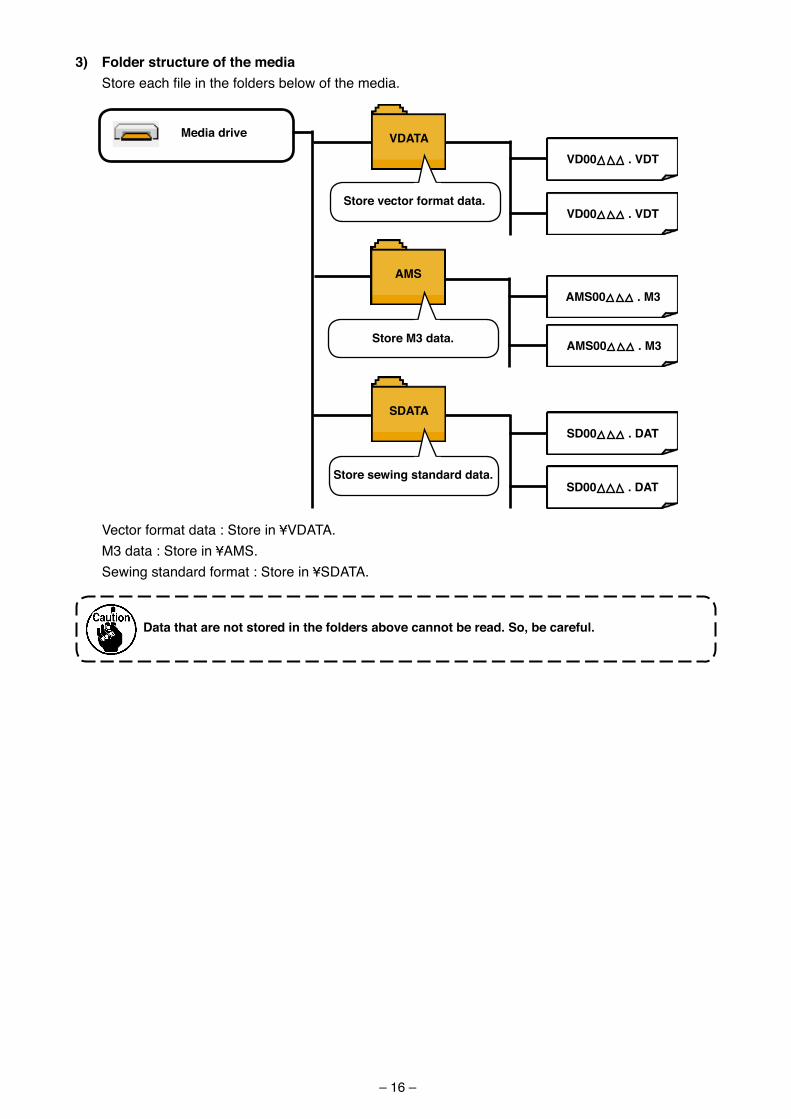
3) Folder structure of the media Store each file in the folders below of the media.
Data that are not stored in the folders above cannot be read. So, be careful.
Media drive
SData
Store sewing standard data.
SD00 . Dat
SD00 . Dat
aMS
Store M3 data.
aMS00 . M3
aMS00 . M3
VDataVD00 . VDt
Store vector format data.VD00 . VDt
Vector format data : Store in ¥VDATA. M3 data : Store in ¥AMS. Sewing standard format : Store in ¥SDATA.
– 17 –
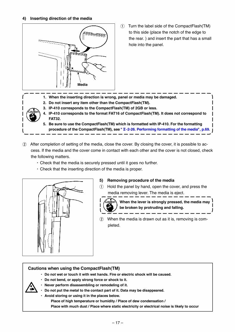
4) Inserting direction of the media
1 Turn the label s�de of the CompactFlash(TM) to th�s s�de (place the notch of the edge to the rear. ) and �nsert the part that has a small hole �nto the panel.
1. When the inserting direction is wrong, panel or media may be damaged. 2. Do not insert any item other than the compactFlash(tM). 3. IP-410 corresponds to the compactFlash(tM) of 2GB or less. 4. IP-410 corresponds to the format Fat16 of compactFlash(tM). It does not correspond to
Fat32. 5. Be sure to use the compactFlash(tM) which is formatted with IP-410. For the formatting
procedure of the compactFlash(tM), see "@-2-26. Performing formatting of the media", p.69.
2 After complet�on of sett�ng of the med�a, close the cover. By clos�ng the cover, �t �s poss�ble to ac-cess. If the med�a and the cover come �n contact w�th each other and the cover �s not closed, check the follow�ng matters.
• Check that the med�a �s securely pressed unt�l �t goes no further. • Check that the �nsert�ng d�rect�on of the med�a �s proper.
5) removing procedure of the media1 Hold the panel by hand, open the cover, and press the
med�a remov�ng lever. The med�a �s eject.
When the lever is strongly pressed, the media may be broken by protruding and falling.
2 When the med�a �s drawn out as �t �s, remov�ng �s com-pleted.
cautions when using the compactFlash(tM)• Do not wet or touch it with wet hands. Fire or electric shock will be caused. • Do not bend, or apply strong force or shock to it.• Never perform disassembling or remodeling of it.• Do not put the metal to the contact part of it. Data may be disappeared.• avoid storing or using it in the places below. Place of high temperature or humidity / Place of dew condensation / Place with much dust / Place where static electricity or electrical noise is likely to occur
Media
– 18 –
2. WHEN uSING IP-410
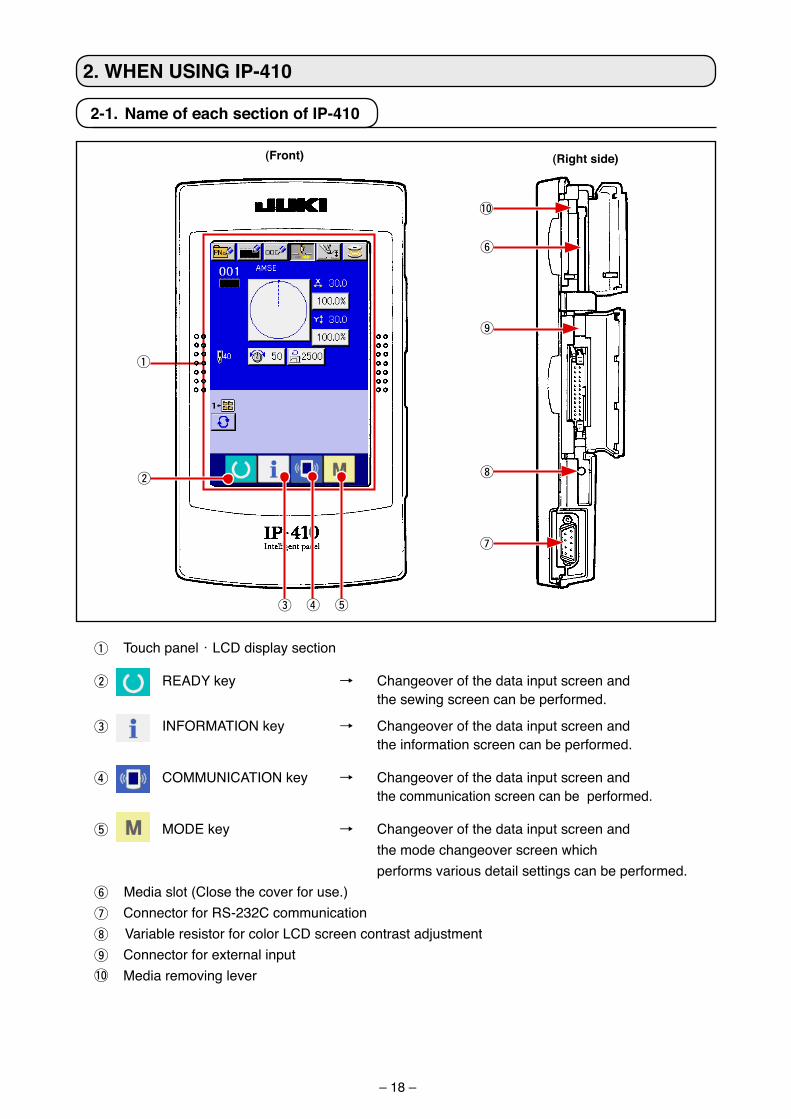
2-1. Name of each section of IP-410
1 Touch panel・LCD d�splay sect�on
2 READY key → Changeover of the data �nput screen and the sew�ng screen can be performed.
3 INFORMATION key → Changeover of the data �nput screen and the �nformat�on screen can be performed.
4 COMMUNICATION key → Changeover of the data �nput screen and the commun�cat�on screen can be performed.
5 MODE key → Changeover of the data �nput screen and the mode changeover screen wh�ch
performs var�ous deta�l sett�ngs can be performed.6 Med�a slot (Close the cover for use.)7 Connector for RS-232C commun�cat�on8 Var�able res�stor for color LCD screen contrast adjustment 9 Connector for external �nput!0 Med�a remov�ng lever
(Front) (right side)
1
3
2
4 5
8
6
7
9
!0
– 19 –
2-2. Buttons to be used in common
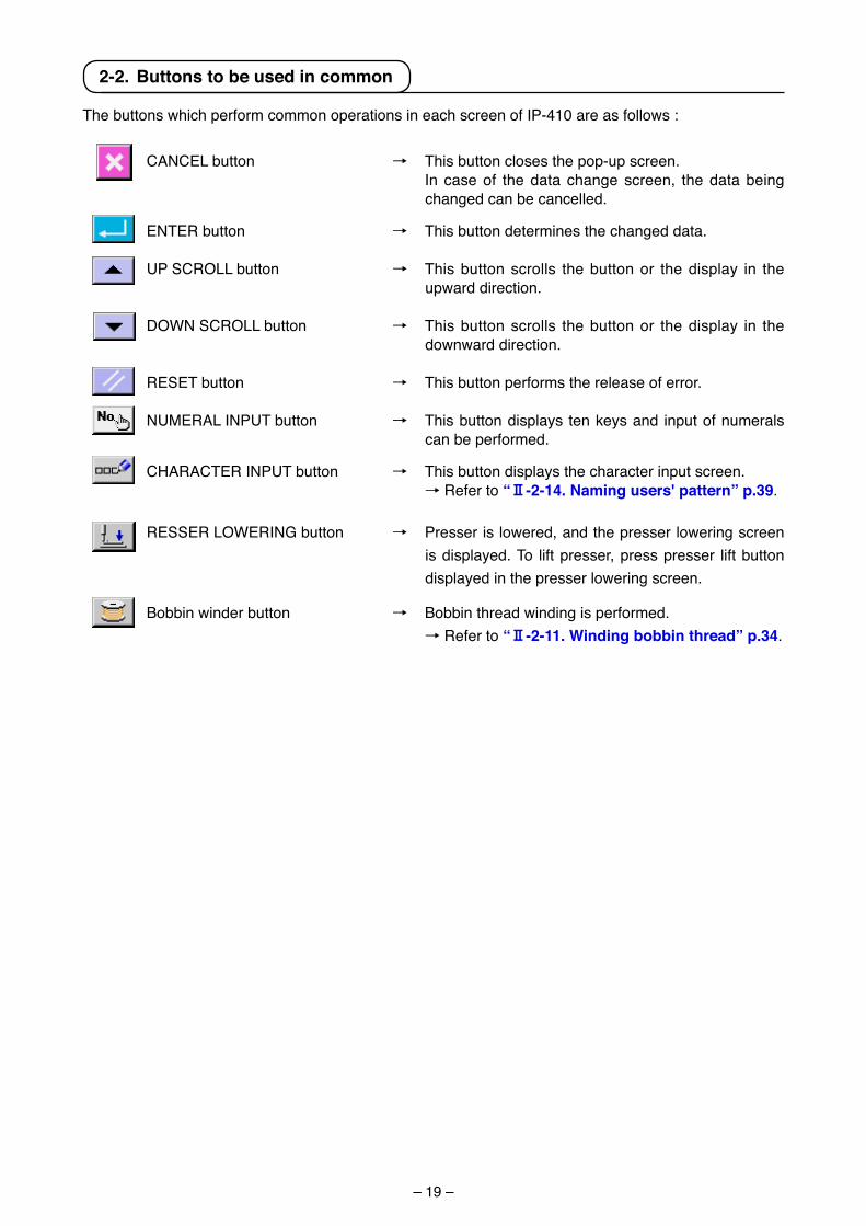
The buttons wh�ch perform common operat�ons �n each screen of IP-410 are as follows :
CANCEL button → Th�s button closes the pop-up screen. In case of the data change screen, the data be�ng
changed can be cancelled.
ENTER button → Th�s button determ�nes the changed data.
UP SCROLL button → Th�s button scrolls the button or the d�splay �n the upward d�rect�on.
DOWN SCROLL button → Th�s button scrolls the button or the d�splay �n the downward d�rect�on.
RESET button → Th�s button performs the release of error.
NUMERAL INPUT button → Th�s button d�splays ten keys and �nput of numerals can be performed.
CHARACTER INPUT button → Th�s button d�splays the character �nput screen. → Refer to “@-2-14. Naming users' pattern” p.39.
RESSER LOWERING button → Presser �s lowered, and the presser lower�ng screen �s d�splayed. To l�ft presser, press presser l�ft button d�splayed �n the presser lower�ng screen.
Bobb�n w�nder button → Bobb�n thread w�nd�ng �s performed. → Refer to “@-2-11. Winding bobbin thread” p.34.
– 20 –
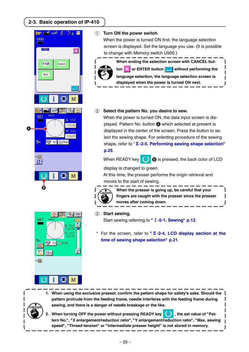
3 Start sewing. Start sew�ng referr�ng to "!-5-1. Sewing" p.12.
* For the screen, refer to "@-2-4. LcD display section at the time of sewing shape selection" p.21.
1.Whenusingtheexclusivepresser,confirmthepatternshapeforsafety'ssake.Shouldthepattern protrude from the feeding frame, needle interferes with the feeding frame during sewing, and there is a danger of needle breakage or the like.
2. When turning oFF the power without pressing rEaDY key , the set value of "Pat-tern No.", "X enlargement/reduction ratio", "Y enlargement/reduction ratio", "Max. sewing speed", "thread tension" or "Intermediate presser height" is not stored in memory.
1 turn oN the power switch When the power is turned ON first, the language selection
screen �s d�splayed. Set the language you use. (It �s poss�ble to change w�th Memory sw�tch U500.)
When ending the selection screen with caNcEL but-
ton or ENtEr button without performing the
language selection, the language selection screen is displayed when the power is turned oN next.
2-3. Basic operation of IP-410
A
B
2 Select the pattern No. you desire to sew. When the power �s turned ON, the data �nput screen �s d�s-
played. Pattern No. button A wh�ch selected at present �s d�splayed �n the center of the screen. Press the button to se-lect the sew�ng shape. For select�ng procedure of the sew�ng shape, refer to "@-2-5. Performing sewing shape selection" p.25.
When READY key B �s pressed, the back color of LCD
d�splay �s changed to green. At th�s t�me, the presser performs the or�g�n retr�eval and
moves to the start of sew�ng.
When the presser is going up, be careful that your fingersarecaughtwiththepressersincethepressermoves after coming down.
– 21 –
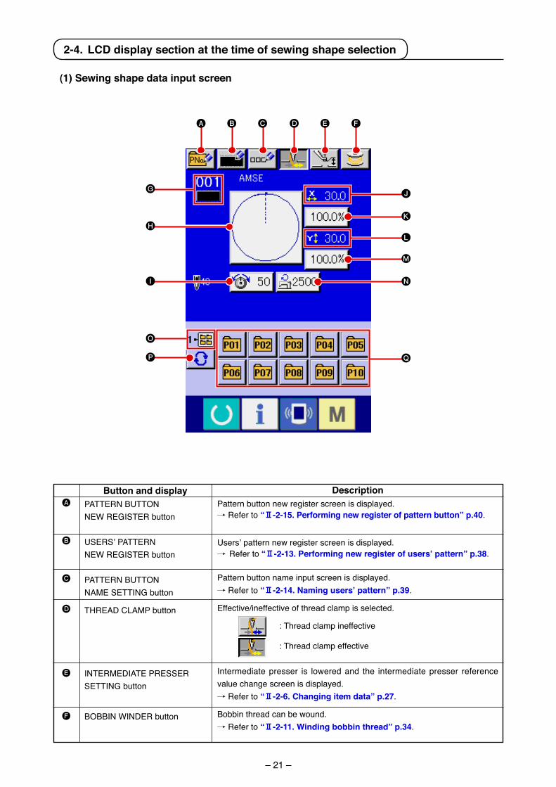
(1) Sewing shape data input screen
A
B
C
D
E
F
Button and displayPATTERN BUTTON NEW REGISTER button
USERS’ PATTERN NEW REGISTER button
PATTERN BUTTON NAME SETTING button
THREAD CLAMP button
INTERMEDIATE PRESSER SETTING button
BOBBIN WINDER button
DescriptionPattern button new reg�ster screen �s d�splayed./ Refer to “@-2-15. Performing new register of pattern button” p.40.
Users’ pattern new reg�ster screen �s d�splayed./ Refer to “@-2-13. Performing new register of users’ pattern” p.38.
Pattern button name �nput screen �s d�splayed./ Refer to “@-2-14. Naming users’ pattern” p.39.
Effect�ve/�neffect�ve of thread clamp �s selected.
: Thread clamp �neffect�ve
: Thread clamp effect�ve
Intermed�ate presser �s lowered and the �ntermed�ate presser reference value change screen �s d�splayed./ Refer to “@-2-6. changing item data” p.27.
Bobb�n thread can be wound./ Refer to “@-2-11. Winding bobbin thread” p.34.
B C D E F
GJ
M
K
L
NI
O
P Q
H
A
2-4. LcD display section at the time of sewing shape selection
– 22 –
G
H
I
J
K
L
M
N
O
P
Q
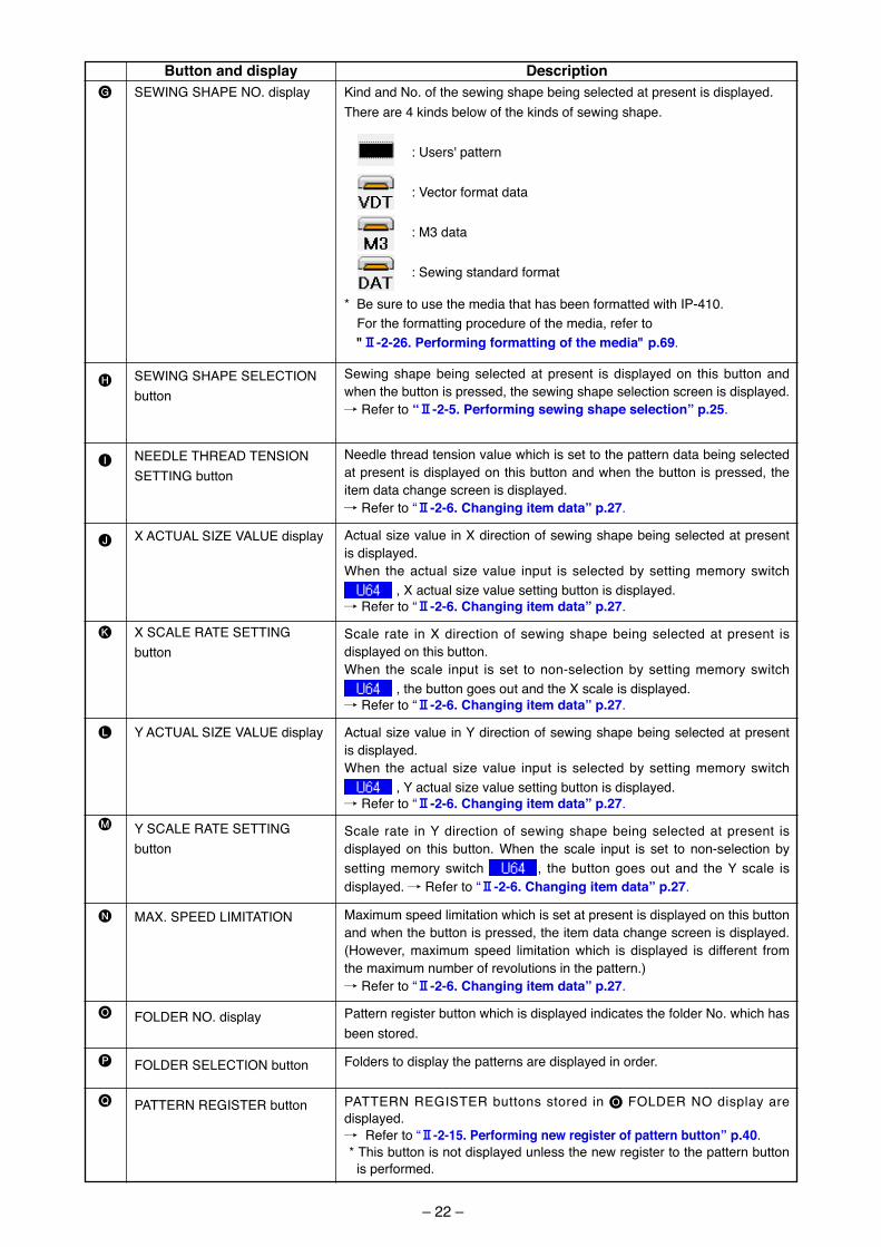
Button and displaySEWING SHAPE NO. d�splay
SEWING SHAPE SELECTIONbutton
NEEDLE THREAD TENSION SETTING button
X ACTUAL SIZE VALUE d�splay
X SCALE RATE SETTING button
Y ACTUAL SIZE VALUE d�splay
Y SCALE RATE SETTING button
MAX. SPEED LIMITATION
FOLDER NO. d�splay
FOLDER SELECTION button
PATTERN REGISTER button
DescriptionK�nd and No. of the sew�ng shape be�ng selected at present �s d�splayed.There are 4 k�nds below of the k�nds of sew�ng shape. : Users' pattern
: Vector format data
: M3 data
: Sew�ng standard format
* Be sure to use the med�a that has been formatted w�th IP-410. For the formatt�ng procedure of the med�a, refer to "@-2-26. Performing formatting of the media" p.69.
Sew�ng shape be�ng selected at present �s d�splayed on th�s button and when the button �s pressed, the sew�ng shape select�on screen �s d�splayed./ Refer to “@-2-5. Performing sewing shape selection” p.25.
Needle thread tens�on value wh�ch �s set to the pattern data be�ng selected at present �s d�splayed on th�s button and when the button �s pressed, the �tem data change screen �s d�splayed./ Refer to “@-2-6. changing item data” p.27.
Actual s�ze value �n X d�rect�on of sew�ng shape be�ng selected at present �s d�splayed.When the actual s�ze value �nput �s selected by sett�ng memory sw�tch
, X actual s�ze value sett�ng button �s d�splayed./ Refer to “@-2-6. changing item data” p.27.
Scale rate �n X d�rect�on of sew�ng shape be�ng selected at present �s d�splayed on th�s button.When the scale �nput �s set to non-select�on by sett�ng memory sw�tch
, the button goes out and the X scale �s d�splayed./ Refer to “@-2-6. changing item data” p.27.
Actual s�ze value �n Y d�rect�on of sew�ng shape be�ng selected at present �s d�splayed.When the actual s�ze value �nput �s selected by sett�ng memory sw�tch
, Y actual s�ze value sett�ng button �s d�splayed./ Refer to “@-2-6. changing item data” p.27.
Scale rate �n Y d�rect�on of sew�ng shape be�ng selected at present �s d�splayed on th�s button. When the scale �nput �s set to non-select�on by sett�ng memory sw�tch , the button goes out and the Y scale �s d�splayed. / Refer to “@-2-6. changing item data” p.27.
Max�mum speed l�m�tat�on wh�ch �s set at present �s d�splayed on th�s button and when the button �s pressed, the �tem data change screen �s d�splayed. (However, max�mum speed l�m�tat�on wh�ch �s d�splayed �s d�fferent from the max�mum number of revolut�ons �n the pattern.)/ Refer to “@-2-6. changing item data” p.27.
Pattern reg�ster button wh�ch �s d�splayed �nd�cates the folder No. wh�ch has been stored.
Folders to d�splay the patterns are d�splayed �n order.
PATTERN REGISTER buttons stored �n O FOLDER NO d�splay are d�splayed./ Refer to “@-2-15. Performing new register of pattern button” p.40. * Th�s button �s not d�splayed unless the new reg�ster to the pattern button
�s performed.
– 23 –
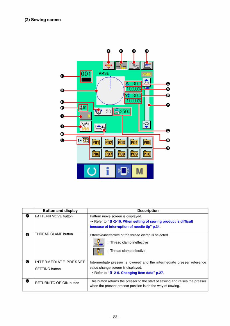
(2) Sewing screen
A
B
C
D
Button and displayPATTERN MOVE button
THREAD CLAMP button
INTERMEDIATE PRESSER
SETTING button
RETURN TO ORIGIN button
DescriptionPattern move screen �s d�splayed.→ Refer to “@-2-10.Whensettingofsewingproductisdifficultbecause of interruption of needle tip” p.34.
Effect�ve/�neffect�ve of the thread clamp �s selected.
: Thread clamp �neffect�ve
: Thread clamp effect�ve
Intermed�ate presser �s lowered and the �ntermed�ate presser reference value change screen �s d�splayed./ Refer to “@-2-6. changing item data” p.27.
Th�s button returns the presser to the start of sew�ng and ra�ses the presser when the present presser pos�t�on �s on the way of sew�ng.
R
A B C D
E
G
J
I
H
P
N
O
M
QK
F
S
L
– 24 –
E
F
G
H
I
J
K
L
M
N
O
P
Q
R
S
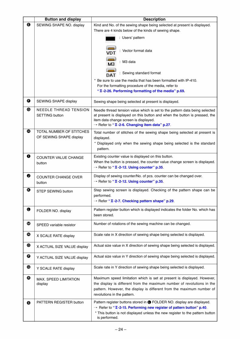
Button and displaySEWING SHAPE NO. d�splay
SEWING SHAPE d�splay
NEEDLE THREAD TENSION SETTING button
TOTAL NUMBER OF STITCHES OF SEWING SHAPE d�splay
COUNTER VALUE CHANGE button
COUNTER CHANGE OVER button
STEP SEWING button
FOLDER NO. d�splay
SPEED var�able res�stor
X SCALE RATE d�splay
X ACTUAL SIZE VALUE d�splay
Y ACTUAL SIZE VALUE d�splay
Y SCALE RATE d�splay
MAX. SPEED LIMITATION d�splay
PATTERN REGISTER button
DescriptionK�nd and No. of the sew�ng shape be�ng selected at present �s d�splayed.There are 4 k�nds below of the k�nds of sew�ng shape.
: Users' pattern
: Vector format data
: M3 data
: Sew�ng standard format
* Be sure to use the med�a that has been formatted w�th IP-410. For the formatt�ng procedure of the med�a, refer to “@-2-26. Performing formatting of the media” p.69.
Sew�ng shape be�ng selected at present �s d�splayed.
Needle thread tens�on value wh�ch �s set to the pattern data be�ng selected at present �s d�splayed on th�s button and when the button �s pressed, the �tem data change screen �s d�splayed./ Refer to “@-2-6. changing item data” p.27.
Total number of st�tches of the sew�ng shape be�ng selected at present �s d�splayed.* D�splayed only when the sew�ng shape be�ng selected �s the standard
pattern.
Ex�st�ng counter value �s d�splayed on th�s button.When the button �s pressed, the counter value change screen �s d�splayed. / Refer to “@-2-12. using counter” p.35.
D�splay of sew�ng counter/No. of pcs. counter can be changed over./ Refer to “@-2-12. using counter” p.35.
Step sew�ng screen �s d�splayed. Check�ng of the pattern shape can be performed./ Refer “@-2-7. checking pattern shape” p.29.
Pattern reg�ster button wh�ch �s d�splayed �nd�cates the folder No. wh�ch has been stored.
Number of rotat�ons of the sew�ng mach�ne can be changed.
Scale rate �n X d�rect�on of sew�ng shape be�ng selected �s d�splayed.
Actual s�ze value �n X d�rect�on of sew�ng shape be�ng selected �s d�splayed.
Actual s�ze value �n Y d�rect�on of sew�ng shape be�ng selected �s d�splayed.
Scale rate �n Y d�rect�on of sew�ng shape be�ng selected �s d�splayed.
Max�mum speed l�m�tat�on wh�ch �s set at present �s d�splayed. However, the d�splay �s d�fferent from the max�mum number of revolut�ons �n the pattern. However, the d�splay �s d�fferent from the max�mum number of revolut�ons �n the pattern.
Pattern reg�ster buttons stored �n L FOLDER NO. d�splay are d�splayed./ Refer to “@-2-15. Performing new register of pattern button” p.40. * Th�s button �s not d�splayed unless the new reg�ster to the pattern button
�s performed.
– 25 –
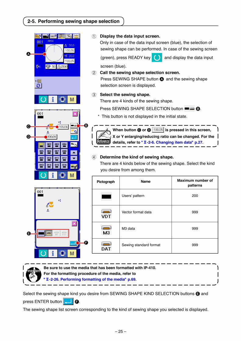
1 Display the data input screen. Only �n case of the data �nput screen (blue), the select�on of
sew�ng shape can be performed. In case of the sew�ng screen
(green), press READY key and d�splay the data �nput
screen (blue).2 call the sewing shape selection screen. Press SEWING SHAPE button A and the sew�ng shape
select�on screen �s d�splayed.
2-5. Performing sewing shape selection
3 Select the sewing shape. There are 4 k�nds of the sew�ng shape.
Press SEWING SHAPE SELECTION button B.
* Th�s button �s not d�splayed �n the �n�t�al state.
4 Determine the kind of sewing shape. There are 4 k�nds below of the sew�ng shape. Select the k�nd
you des�re from among them.
Pictograph Name
Users' pattern
Vector format data
M3 data
Sew�ng standard format
Maximum number of patterns
200
999
999
999
Select the sew�ng shape k�nd you des�re from SEWING SHAPE KIND SELECTION buttons E and
press ENTER button F.
The sew�ng shape l�st screen correspond�ng to the k�nd of sew�ng shape you selected �s d�splayed.
When button C or D is pressed in this screen, X or Y enlarging/reducing ratio can be changed. For the details, refer to "@-2-6. changing item data" p.27.
Be sure to use the media that has been formatted with IP-410. For the formatting procedure of the media, refer to "@-2-26. Performing formatting of the media" p.69.
A
C
D
B
F
E
– 26 –
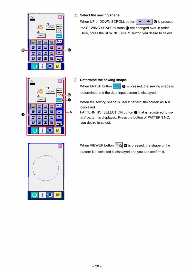
5 Select the sewing shape.
When UP or DOWN SCROLL button G �s pressed,
the SEWING SHAPE buttons H are changed over �n order. Here, press the SEWING SHAPE button you des�re to select.
6 Determine the sewing shape.
When ENTER button I �s pressed, the sew�ng shape �s
determ�ned and the data �nput screen �s d�splayed.
When the sew�ng shape �s users' pattern, the screen as a �s d�splayed.
PATTERN NO. SELECTION button J that �s reg�stered to us-ers' pattern �s d�splayed. Press the button of PATTERN NO. you des�re to select.
a
When VIEWER button K �s pressed, the shape of the
pattern No. selected is displayed and you can confirm it.
H G
J
I
K
– 27 –
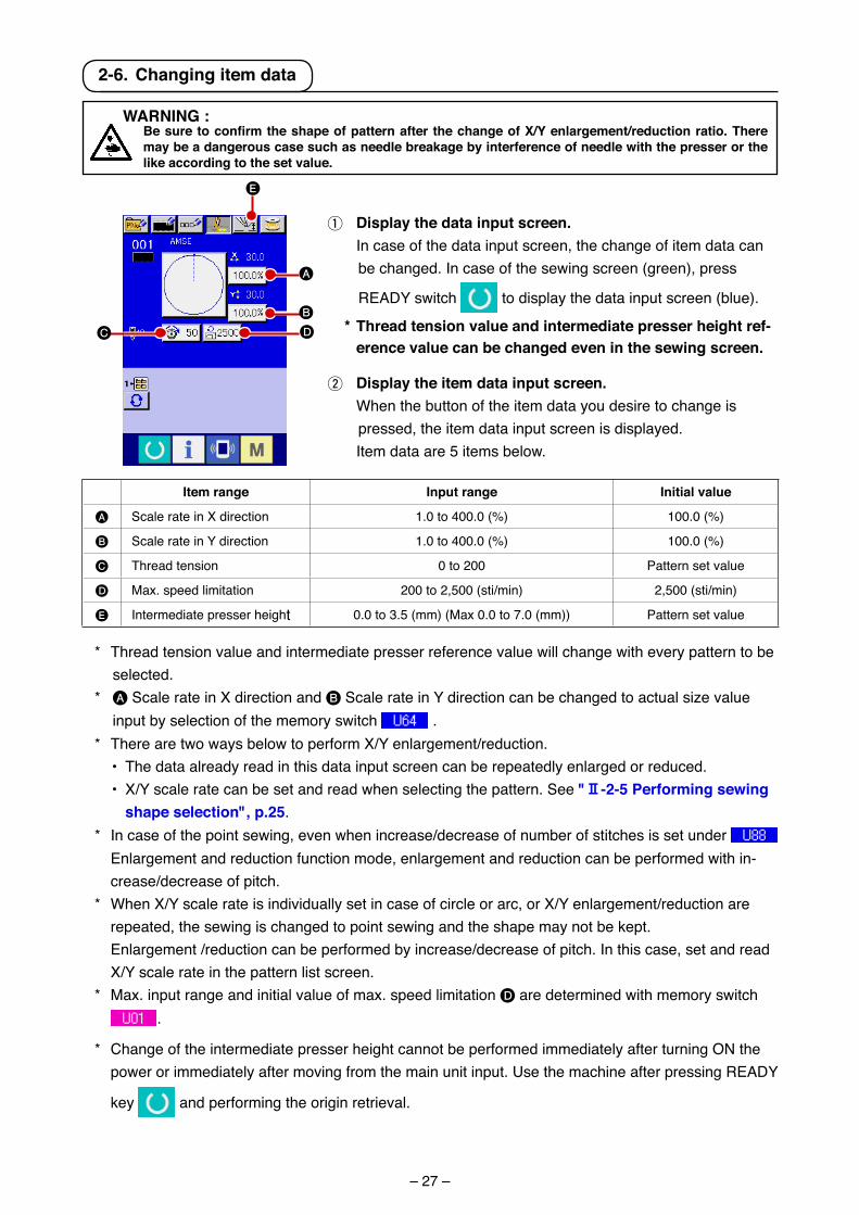
1 Display the data input screen. In case of the data �nput screen, the change of �tem data can
be changed. In case of the sew�ng screen (green), press
READY sw�tch to d�splay the data �nput screen (blue).
* thread tension value and intermediate presser height ref-erence value can be changed even in the sewing screen.
2 Display the item data input screen. When the button of the �tem data you des�re to change �s
pressed, the �tem data �nput screen �s d�splayed. Item data are 5 �tems below.
* Thread tens�on value and �ntermed�ate presser reference value w�ll change w�th every pattern to be selected.
* A Scale rate �n X d�rect�on and B Scale rate �n Y d�rect�on can be changed to actual s�ze value �nput by select�on of the memory sw�tch .
* There are two ways below to perform X/Y enlargement/reduct�on. • The data already read �n th�s data �nput screen can be repeatedly enlarged or reduced. • X/Y scale rate can be set and read when select�ng the pattern. See "@-2-5 Performing sewing
shape selection", p.25. * In case of the po�nt sew�ng, even when �ncrease/decrease of number of st�tches �s set under
Enlargement and reduct�on funct�on mode, enlargement and reduct�on can be performed w�th �n-crease/decrease of p�tch.
* When X/Y scale rate �s �nd�v�dually set �n case of c�rcle or arc, or X/Y enlargement/reduct�on are repeated, the sew�ng �s changed to po�nt sew�ng and the shape may not be kept.
Enlargement /reduct�on can be performed by �ncrease/decrease of p�tch. In th�s case, set and read X/Y scale rate �n the pattern l�st screen.
* Max. �nput range and �n�t�al value of max. speed l�m�tat�on D are determ�ned w�th memory sw�tch .
* Change of the �ntermed�ate presser he�ght cannot be performed �mmed�ately after turn�ng ON the power or �mmed�ately after mov�ng from the ma�n un�t �nput. Use the mach�ne after press�ng READY
key and perform�ng the or�g�n retr�eval.
A
B
DC
E
2-6. changing item data
Item range Input range Initial value
A Scale rate �n X d�rect�on 1.0 to 400.0 (%) 100.0 (%)
B Scale rate �n Y d�rect�on 1.0 to 400.0 (%) 100.0 (%)
C Thread tens�on 0 to 200 Pattern set value
D Max. speed l�m�tat�on 200 to 2,500 (st�/m�n) 2,500 (st�/m�n)
E Intermed�ate presser he�ght 0.0 to 3.5 (mm) (Max 0.0 to 7.0 (mm)) Pattern set value
WarNING : BesuretoconfirmtheshapeofpatternafterthechangeofX/Yenlargement/reductionratio.There
may be a dangerous case such as needle breakage by interference of needle with the presser or the like according to the set value.
– 28 –
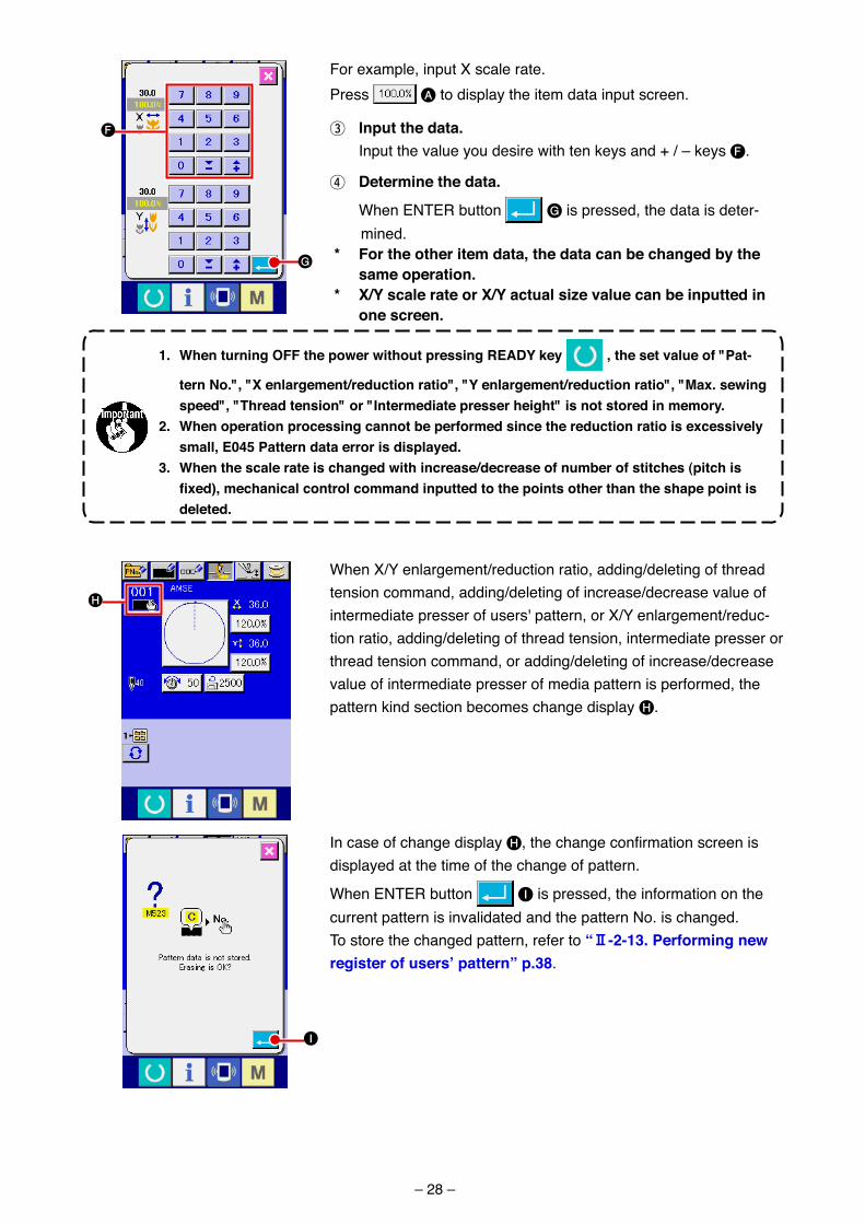
For example, �nput X scale rate.Press A to d�splay the �tem data �nput screen.
3 Input the data. Input the value you des�re w�th ten keys and + / – keys F.
4 Determine the data.
When ENTER button G �s pressed, the data �s deter-m�ned.
* For the other item data, the data can be changed by the same operation.
* X/Y scale rate or X/Y actual size value can be inputted in one screen.
1. When turning oFF the power without pressing rEaDY key , the set value of "Pat-
tern No.", "X enlargement/reduction ratio", "Y enlargement/reduction ratio", "Max. sewing speed", "thread tension" or "Intermediate presser height" is not stored in memory.
2. When operation processing cannot be performed since the reduction ratio is excessively small, E045 Pattern data error is displayed.
3. When the scale rate is changed with increase/decrease of number of stitches (pitch is fixed),mechanicalcontrolcommandinputtedtothepointsotherthantheshapepointisdeleted.
H
I
In case of change d�splay H, the change confirmation screen is d�splayed at the t�me of the change of pattern.
When ENTER button I �s pressed, the �nformat�on on the current pattern �s �nval�dated and the pattern No. �s changed.To store the changed pattern, refer to “@-2-13. Performing new register of users’ pattern” p.38.
G
F
When X/Y enlargement/reduct�on rat�o, add�ng/delet�ng of thread tens�on command, add�ng/delet�ng of �ncrease/decrease value of �ntermed�ate presser of users' pattern, or X/Y enlargement/reduc-t�on rat�o, add�ng/delet�ng of thread tens�on, �ntermed�ate presser or thread tens�on command, or add�ng/delet�ng of �ncrease/decrease value of �ntermed�ate presser of med�a pattern �s performed, the pattern k�nd sect�on becomes change d�splay H.
– 29 –
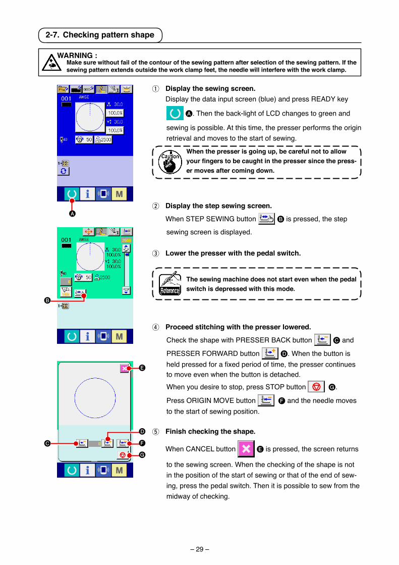
1 Display the sewing screen. D�splay the data �nput screen (blue) and press READY key
A. Then the back-l�ght of LCD changes to green and
sew�ng �s poss�ble. At th�s t�me, the presser performs the or�g�n retr�eval and moves to the start of sew�ng.
4 Proceed stitching with the presser lowered.
Check the shape w�th PRESSER BACK button C and
PRESSER FORWARD button D. When the button �s held pressed for a fixed period of time, the presser continues to move even when the button �s detached.
When you des�re to stop, press STOP button G.
Press ORIGIN MOVE button F and the needle moves to the start of sew�ng pos�t�on.
5 Finish checking the shape.
When CANCEL button E �s pressed, the screen returns
to the sew�ng screen. When the check�ng of the shape �s not �n the pos�t�on of the start of sew�ng or that of the end of sew-�ng, press the pedal sw�tch. Then �t �s poss�ble to sew from the m�dway of check�ng.
the sewing machine does not start even when the pedal switch is depressed with this mode.
2 Display the step sewing screen.
When STEP SEWING button B �s pressed, the step
sew�ng screen �s d�splayed.
3 Lower the presser with the pedal switch.
WarNING : Make sure without fail of the contour of the sewing pattern after selection of the sewing pattern. If the
sewing pattern extends outside the work clamp feet, the needle will interfere with the work clamp.
2-7. checking pattern shape
A
B
E
D
F
G
C
When the presser is going up, be careful not to allow yourfingerstobecaughtinthepressersincethepress-er moves after coming down.
– 30 –
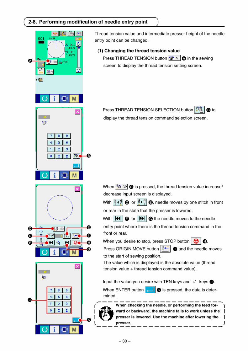
(1) changing the thread tension value Press THREAD TENSION button A �n the sew�ng
screen to d�splay the thread tens�on sett�ng screen.
Press THREAD TENSION SELECTION button B to
d�splay the thread tens�on command select�on screen.
When C �s pressed, the thread tens�on value �ncrease/decrease �nput screen �s d�splayed.
W�th D or E, needle moves by one st�tch �n front
or rear �n the state that the presser �s lowered.
W�th F or G the needle moves to the needle
entry po�nt where there �s the thread tens�on command �n the front or rear.
When you des�re to stop, press STOP button H. Press ORIGIN MOVE button I and the needle moves
to the start of sew�ng pos�t�on. The value wh�ch �s d�splayed �s the absolute value (thread
tens�on value + thread tens�on command value).
Input the value you des�re w�th TEN keys and +/– keys J.
When ENTER button K �s pressed, the data �s deter-m�ned.
Thread tens�on value and �ntermed�ate presser he�ght of the needle entry po�nt can be changed.
When checking the needle, or performing the feed for-ward or backward, the machine fails to work unless the presser is lowered. use the machine after lowering the presser.
2-8.Performingmodificationofneedleentrypoint
A
B
J
K
C
D
F H
G
E
I
– 31 –
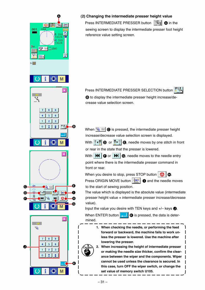
(2) changing the intermediate presser height value Press INTERMEDIATE PRESSER button A �n the
sew�ng screen to d�splay the �ntermed�ate presser foot he�ght reference value sett�ng screen.
Press INTERMEDIATE PRESSER SELECTION button
B to d�splay the �ntermed�ate presser he�ght �ncrease/de-crease value select�on screen.
When C �s pressed, the �ntermed�ate presser he�ght �ncrease/decrease value select�on screen �s d�splayed.
W�th D or E, needle moves by one st�tch �n front
or rear �n the state that the presser �s lowered.
W�th F or G, needle moves to the needle entry
po�nt where there �s the �ntermed�ate presser command �n front or rear.
When you des�re to stop, press STOP button H. Press ORIGIN MOVE button I and the needle moves
to the start of sew�ng pos�t�on. The value wh�ch �s d�splayed �s the absolute value (�ntermed�ate
presser he�ght value + �ntermed�ate presser �ncrease/decrease value).
Input the value you des�re w�th TEN keys and +/– keys J.
When ENTER button K �s pressed, the data �s deter-m�ned.
1. When checking the needle, or performing the feed forward or backward, the machine fails to work un-less the presser is lowered. use the machine after lowering the presser.
2. When increasing the height of intermediate presser ormakingtheneedlesizethicker,confirmtheclear-ance between the wiper and the components. Wiper cannot be used unless the clearance is secured. In this case, turn oFF the wiper switch, or change the set value of memory switch u105.
B
A
K
J
C
D
F H
G
E
I
– 32 –
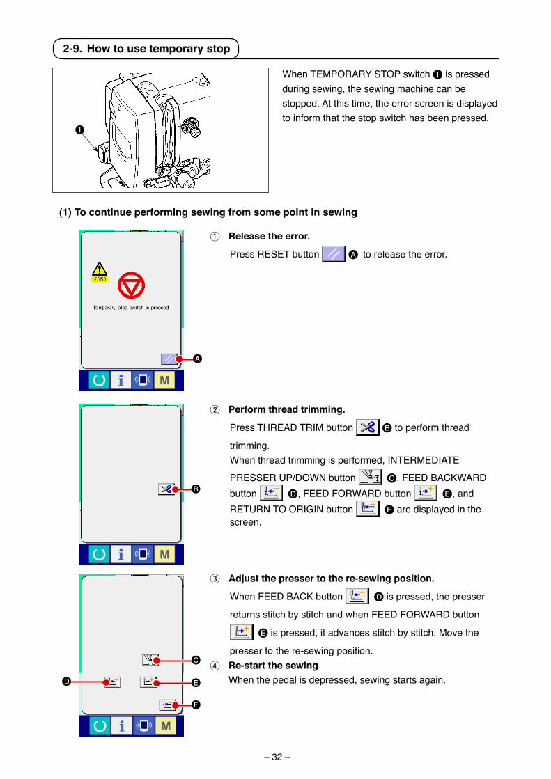
When TEMPORARY STOP sw�tch 1 �s pressed dur�ng sew�ng, the sew�ng mach�ne can be stopped. At th�s t�me, the error screen �s d�splayed to �nform that the stop sw�tch has been pressed.
(1) to continue performing sewing from some point in sewing
1 release the error.
Press RESET button A to release the error.
2 Perform thread trimming.
Press THREAD TRIM button B to perform thread
tr�mm�ng. When thread tr�mm�ng �s performed, INTERMEDIATE
PRESSER UP/DOWN button C, FEED BACKWARD button D, FEED FORWARD button E, and RETURN TO ORIGIN button F are d�splayed �n the screen.
2-9. How to use temporary stop
A
B
C
E
F
D
3 adjust the presser to the re-sewing position.
When FEED BACK button D �s pressed, the presser
returns st�tch by st�tch and when FEED FORWARD button
E �s pressed, �t advances st�tch by st�tch. Move the
presser to the re-sew�ng pos�t�on.4 re-start the sewing When the pedal �s depressed, sew�ng starts aga�n.
1
– 33 –
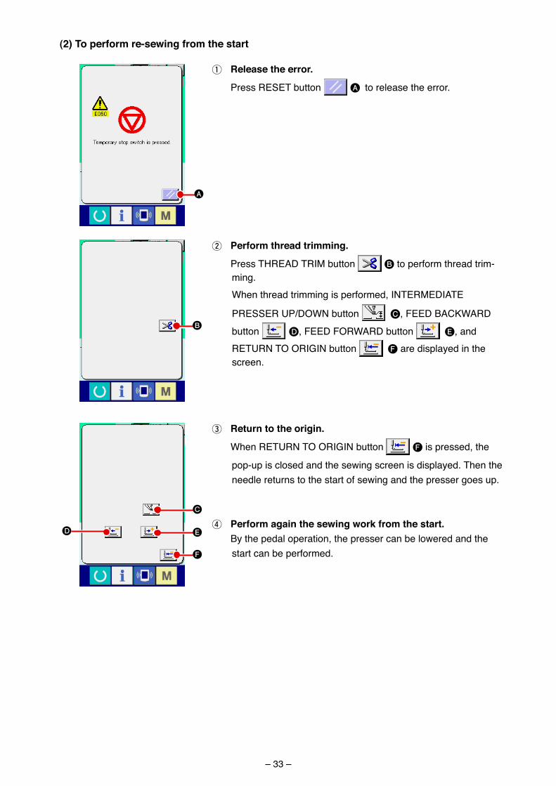
1 release the error.
Press RESET button A to release the error.
(2) to perform re-sewing from the start
3 return to the origin.
When RETURN TO ORIGIN button F �s pressed, the
pop-up �s closed and the sew�ng screen �s d�splayed. Then the needle returns to the start of sew�ng and the presser goes up.
4 Perform again the sewing work from the start. By the pedal operat�on, the presser can be lowered and the
start can be performed.
2 Perform thread trimming.
Press THREAD TRIM button B to perform thread tr�m-m�ng.
When thread tr�mm�ng �s performed, INTERMEDIATE
PRESSER UP/DOWN button C, FEED BACKWARD
button D, FEED FORWARD button E, and RETURN TO ORIGIN button F are d�splayed �n the screen.
A
B
C
E
F
D
– 34 –
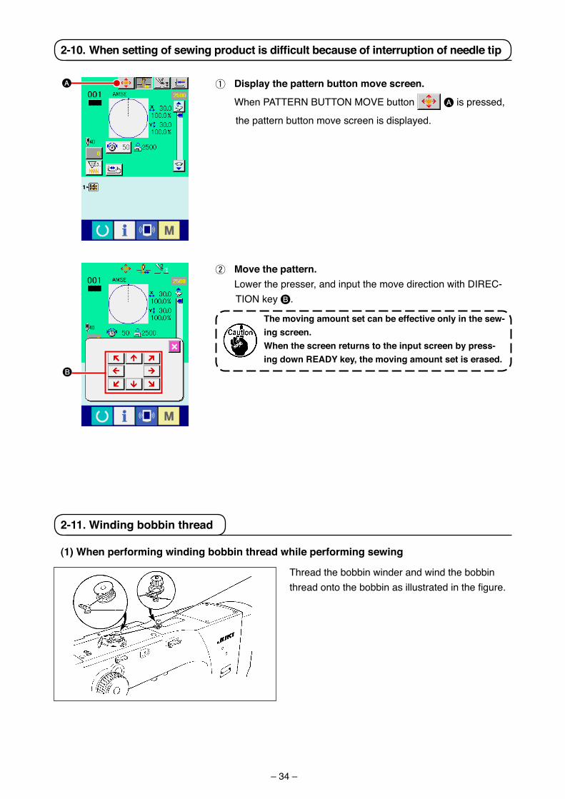
2-11. Winding bobbin thread
(1) When performing winding bobbin thread while performing sewing
Thread the bobb�n w�nder and w�nd the bobb�n thread onto the bobbin as illustrated in the figure.
1 Display the pattern button move screen.
When PATTERN BUTTON MOVE button A �s pressed,
the pattern button move screen �s d�splayed.
2-10.Whensettingofsewingproductisdifficultbecauseofinterruptionofneedletip
A
2 Move the pattern. Lower the presser, and �nput the move d�rect�on w�th DIREC-
TION key B.
the moving amount set can be effective only in the sew-ing screen.When the screen returns to the input screen by press-ing down rEaDY key, the moving amount set is erased.
B
– 35 –
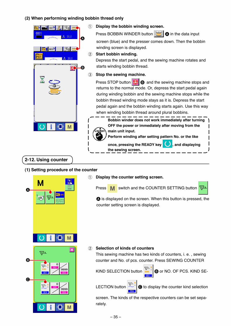
(2) When performing winding bobbin thread only
1 Display the bobbin winding screen.
Press BOBBIN WINDER button A �n the data �nput
screen (blue) and the presser comes down. Then the bobb�n w�nd�ng screen �s d�splayed.
2 Start bobbin winding. Depress the start pedal, and the sew�ng mach�ne rotates and
starts w�nd�ng bobb�n thread.
3 Stop the sewing machine.
Press STOP button B and the sew�ng mach�ne stops and returns to the normal mode. Or, depress the start pedal aga�n dur�ng w�nd�ng bobb�n and the sew�ng mach�ne stops wh�le the bobb�n thread w�nd�ng mode stays as �t �s. Depress the start pedal aga�n and the bobb�n w�nd�ng starts aga�n. Use th�s way when w�nd�ng bobb�n thread around plural bobb�ns.
Bobbin winder does not work immediately after turning oFF the power or immediately after moving from the main unit input. Perform winding after setting pattern No. or the like
once, pressing the rEaDY key , and displaying the sewing screen.
A
B
(1) Setting procedure of the counter1 Display the counter setting screen.
Press sw�tch and the COUNTER SETTING button
A �s d�splayed on the screen. When th�s button �s pressed, the counter sett�ng screen �s d�splayed.
2 Selection of kinds of counters Th�s sew�ng mach�ne has two k�nds of counters, �. e. , sew�ng
counter and No. of pcs. counter. Press SEWING COUNTER
KIND SELECTION button B or NO. OF PCS. KIND SE-
LECTION button C to d�splay the counter k�nd select�on
screen. The k�nds of the respect�ve counters can be set sepa-rately.
2-12. using counter
A
B
C
– 36 –
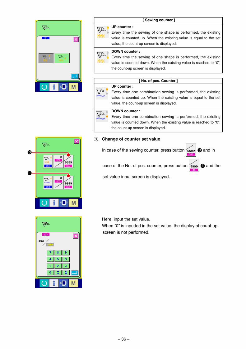
[ Sewing counter ]
uP counter :Every t�me the sew�ng of one shape �s performed, the ex�st�ng value �s counted up. When the ex�st�ng value �s equal to the set value, the count-up screen �s d�splayed.
DoWN counter :Every t�me the sew�ng of one shape �s performed, the ex�st�ng value �s counted down. When the ex�st�ng value �s reached to “0”, the count-up screen �s d�splayed.
[ No. of pcs. counter ]uP counter :Every t�me one comb�nat�on sew�ng �s performed, the ex�st�ng value �s counted up. When the ex�st�ng value �s equal to the set value, the count-up screen �s d�splayed.
DoWN counter :Every t�me one comb�nat�on sew�ng �s performed, the ex�st�ng value �s counted down. When the ex�st�ng value �s reached to “0”, the count-up screen �s d�splayed.
3 change of counter set value
In case of the sew�ng counter, press button D and �n
case of the No. of pcs. counter, press button E and the
set value �nput screen �s d�splayed.
Here, �nput the set value. When “0” �s �nputted �n the set value, the d�splay of count-up
screen �s not performed.
D
E
– 37 –
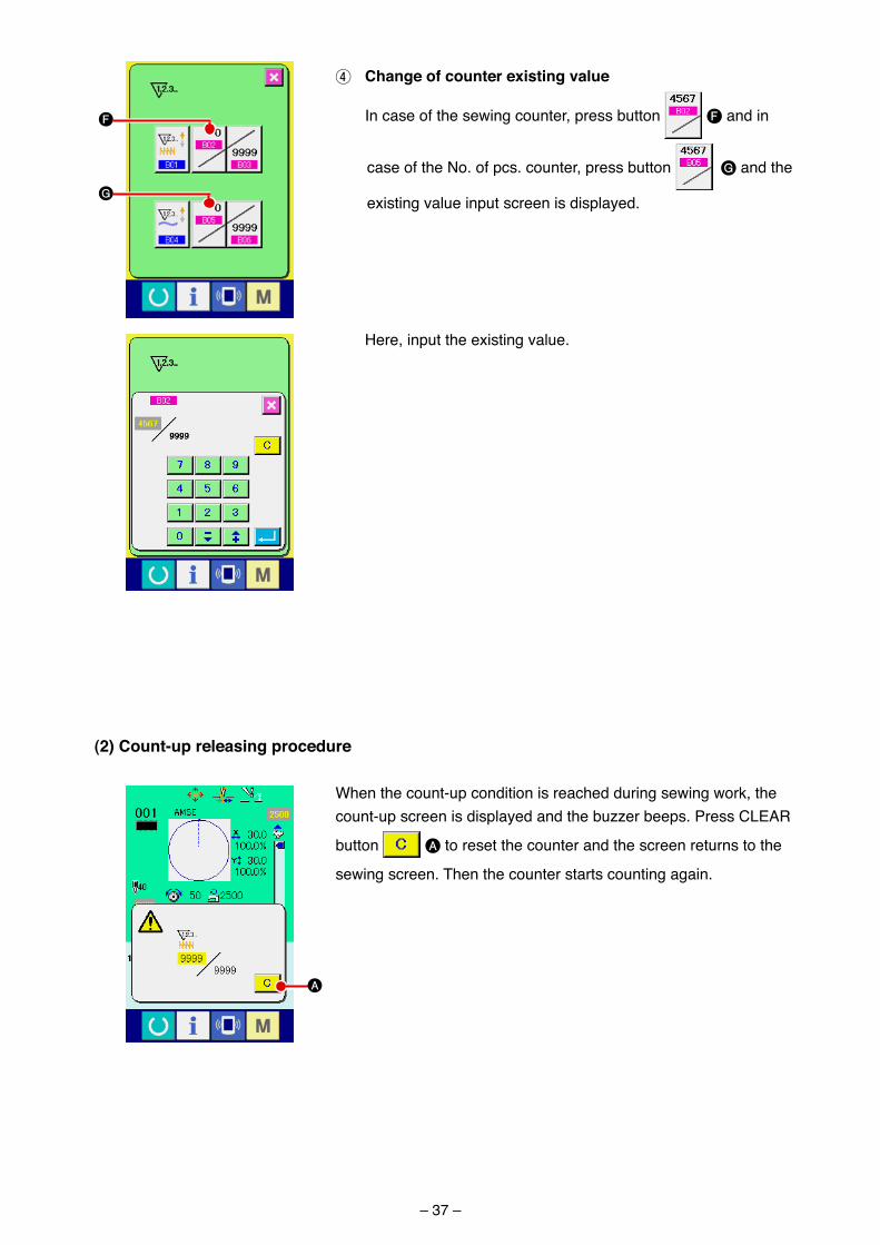
4 change of counter existing value
In case of the sew�ng counter, press button F and �n
case of the No. of pcs. counter, press button G and the
ex�st�ng value �nput screen �s d�splayed.
Here, �nput the ex�st�ng value.
F
G
(2) count-up releasing procedure
When the count-up cond�t�on �s reached dur�ng sew�ng work, the count-up screen �s d�splayed and the buzzer beeps. Press CLEAR
button A to reset the counter and the screen returns to the
sew�ng screen. Then the counter starts count�ng aga�n.
A
– 38 –
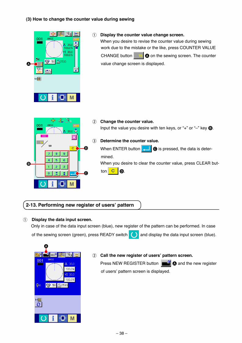
2 change the counter value. Input the value you des�re w�th ten keys, or “+” or “–” key B.
3 Determine the counter value.
When ENTER button C �s pressed, the data �s deter-
m�ned. When you des�re to clear the counter value, press CLEAR but-
ton D.
(3) How to change the counter value during sewing
1 Display the counter value change screen. When you des�re to rev�se the counter value dur�ng sew�ng
work due to the m�stake or the l�ke, press COUNTER VALUE
CHANGE button A on the sew�ng screen. The counter
value change screen �s d�splayed.A
D
B
C
2 call the new register of users’ pattern screen.
Press NEW REGISTER button A and the new reg�ster
of users’ pattern screen �s d�splayed.
2-13. Performing new register of users’ pattern
A
1 Display the data input screen. Only �n case of the data �nput screen (blue), new reg�ster of the pattern can be performed. In case
of the sew�ng screen (green), press READY sw�tch and d�splay the data �nput screen (blue).
– 39 –
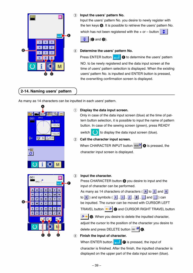
3 Input the users’ pattern No. Input the users’ pattern No. you des�re to newly reg�ster w�th
the ten keys B. It �s poss�ble to retr�eve the users’ pattern No.
wh�ch has not been reg�stered w�th the + or – button
(C and D).
4 Determine the users’ pattern No.
Press ENTER button E to determ�ne the users’ pattern
NO. to be newly reg�stered and the data �nput screen at the t�me of users’ pattern select�on �s d�splayed. When the ex�st�ng users' pattern No. �s �nputted and ENTER button �s pressed, the overwriting confirmation screen is displayed.
B
E
CD
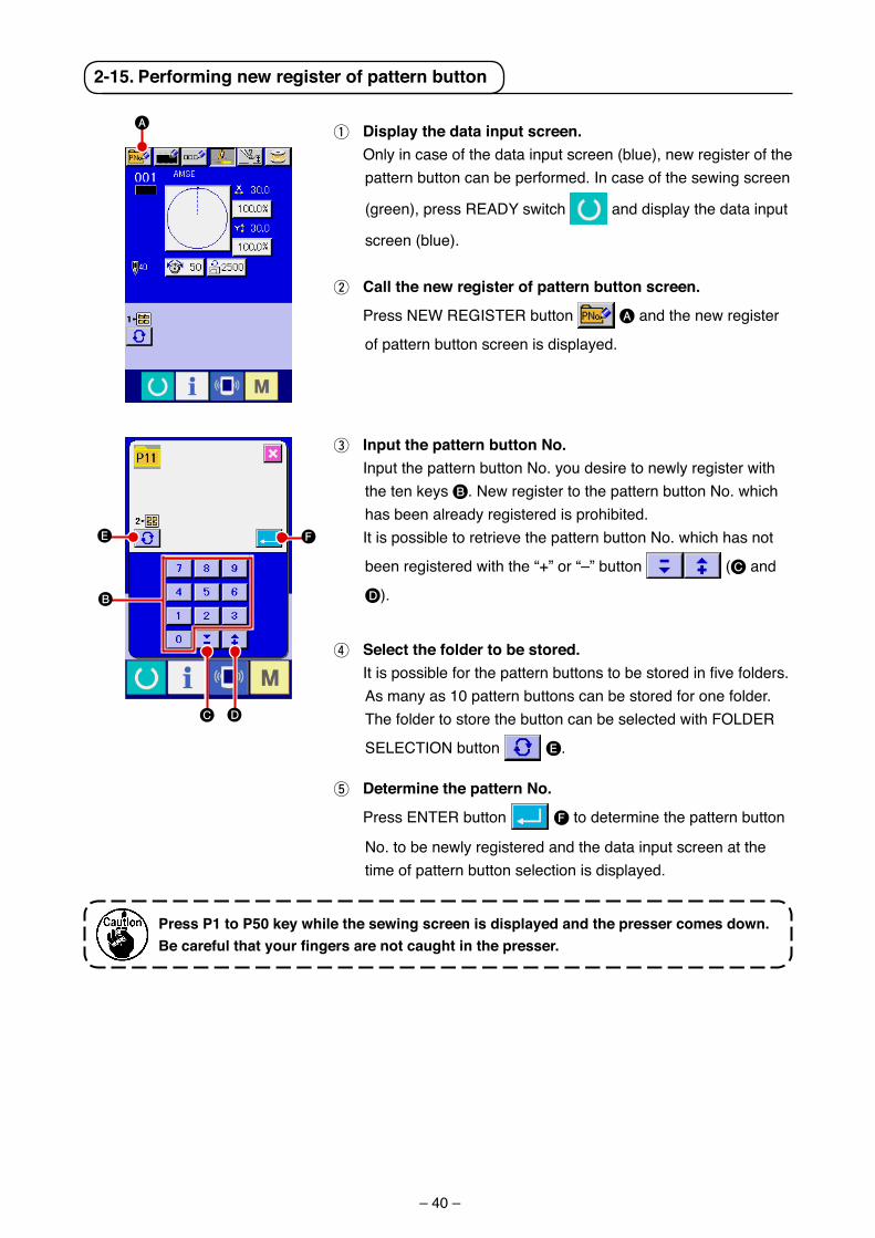
1 Display the data input screen. Only �n case of the data �nput screen (blue) at the t�me of pat-
tern button select�on, �t �s poss�ble to �nput the name of pattern button. In case of the sew�ng screen (green), press READY
sw�tch to d�splay the data �nput screen (blue).
2 call the character input screen.
When CHARACTER INPUT button A �s pressed, the
character �nput screen �s d�splayed.
2-14. Naming users’ pattern
3 Input the character. Press CHARACTER button B you des�re to �nput and the
�nput of character can be performed. As many as 14 characters of characters ( to and
to ) and symbols ( , , , , and ) can be �nputted. The cursor can be moved w�th CURSOR LEFT
TRAVEL button C and CURSOR RIGHT TRAVEL button
D. When you des�re to delete the �nputted character,
adjust the cursor to the pos�t�on of the character you des�re to
delete and press DELETE button E.
4 Finish the input of character.
When ENTER button F �s pressed, the �nput of
character is finished. After the finish, the inputted character is d�splayed on the upper part of the data �nput screen (blue).
As many as 14 characters can be �nputted �n each users' pattern.A
B
C
F
D E
– 40 –
2-15. Performing new register of pattern button
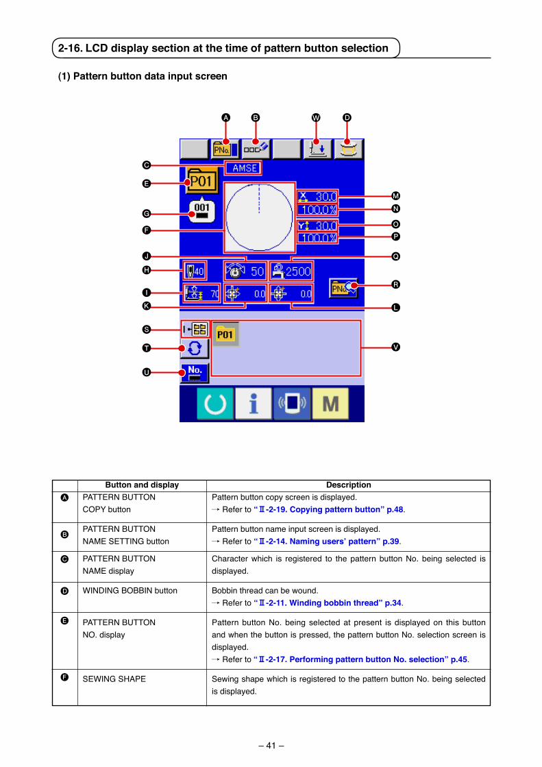
1 Display the data input screen. Only �n case of the data �nput screen (blue), new reg�ster of the
pattern button can be performed. In case of the sew�ng screen
(green), press READY sw�tch and d�splay the data �nput
screen (blue).
2 call the new register of pattern button screen.
Press NEW REGISTER button A and the new reg�ster
of pattern button screen �s d�splayed.
3 Input the pattern button No. Input the pattern button No. you des�re to newly reg�ster w�th
the ten keys B. New reg�ster to the pattern button No. wh�ch has been already reg�stered �s proh�b�ted.
It �s poss�ble to retr�eve the pattern button No. wh�ch has not
been reg�stered w�th the “+” or “–” button (C and
D).
4 Select the folder to be stored. It is possible for the pattern buttons to be stored in five folders.
As many as 10 pattern buttons can be stored for one folder. The folder to store the button can be selected w�th FOLDER
SELECTION button E.
5 Determine the pattern No.
Press ENTER button F to determ�ne the pattern button
No. to be newly reg�stered and the data �nput screen at the t�me of pattern button select�on �s d�splayed.
Press P1 to P50 key while the sewing screen is displayed and the presser comes down. Becarefulthatyourfingersarenotcaughtinthepresser.
A
B
DC
FE
– 41 –
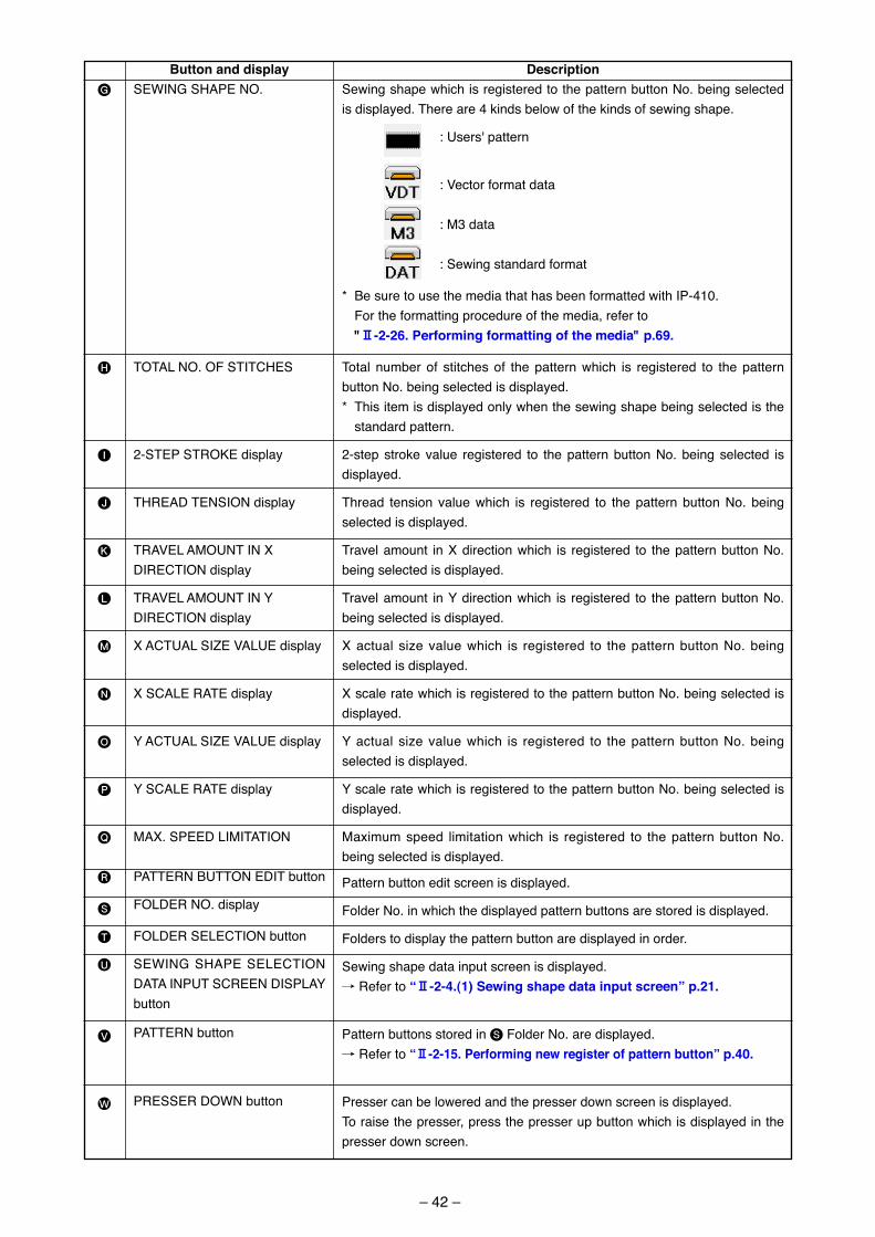
(1) Pattern button data input screen
A
B
C
D
E
F
Button and display PATTERN BUTTONCOPY button
PATTERN BUTTONNAME SETTING button
PATTERN BUTTONNAME d�splay
WINDING BOBBIN button
PATTERN BUTTONNO. d�splay
SEWING SHAPE
DescriptionPattern button copy screen �s d�splayed./ Refer to “@-2-19. copying pattern button” p.48.
Pattern button name �nput screen �s d�splayed./ Refer to “@-2-14. Naming users’ pattern” p.39.
Character wh�ch �s reg�stered to the pattern button No. be�ng selected �s d�splayed.
Bobb�n thread can be wound./ Refer to “@-2-11. Winding bobbin thread” p.34.
Pattern button No. be�ng selected at present �s d�splayed on th�s button and when the button �s pressed, the pattern button No. select�on screen �s d�splayed./ Refer to “@-2-17. Performing pattern button No. selection” p.45.
Sew�ng shape wh�ch �s reg�stered to the pattern button No. be�ng selected �s d�splayed.
2-16. LcD display section at the time of pattern button selection
A B D
T
U
V
S
F
E
G
J
K L
Q
I
H
M
N
O
P
C
W
R
– 42 –
G
H
I
J
K
L
M
N
O
P
Q
R
S
T
U
V
W
Button and display SEWING SHAPE NO.
TOTAL NO. OF STITCHES
2-STEP STROKE d�splay
THREAD TENSION d�splay
TRAVEL AMOUNT IN X DIRECTION d�splay
TRAVEL AMOUNT IN Y DIRECTION d�splay
X ACTUAL SIZE VALUE d�splay
X SCALE RATE d�splay
Y ACTUAL SIZE VALUE d�splay
Y SCALE RATE d�splay
MAX. SPEED LIMITATION
PATTERN BUTTON EDIT button
FOLDER NO. d�splay
FOLDER SELECTION button
SEWING SHAPE SELECTION DATA INPUT SCREEN DISPLAY button
PATTERN button
PRESSER DOWN button
DescriptionSew�ng shape wh�ch �s reg�stered to the pattern button No. be�ng selected �s d�splayed. There are 4 k�nds below of the k�nds of sew�ng shape.
: Users' pattern
: Vector format data
: M3 data
: Sew�ng standard format
* Be sure to use the med�a that has been formatted w�th IP-410. For the formatt�ng procedure of the med�a, refer to "@-2-26. Performing formatting of the media" p.69.
Total number of st�tches of the pattern wh�ch �s reg�stered to the pattern button No. be�ng selected �s d�splayed.* Th�s �tem �s d�splayed only when the sew�ng shape be�ng selected �s the
standard pattern.
2-step stroke value reg�stered to the pattern button No. be�ng selected �s d�splayed.
Thread tens�on value wh�ch �s reg�stered to the pattern button No. be�ng selected �s d�splayed.
Travel amount �n X d�rect�on wh�ch �s reg�stered to the pattern button No. be�ng selected �s d�splayed.
Travel amount �n Y d�rect�on wh�ch �s reg�stered to the pattern button No. be�ng selected �s d�splayed.
X actual s�ze value wh�ch �s reg�stered to the pattern button No. be�ng selected �s d�splayed.
X scale rate wh�ch �s reg�stered to the pattern button No. be�ng selected �s d�splayed.
Y actual s�ze value wh�ch �s reg�stered to the pattern button No. be�ng selected �s d�splayed.
Y scale rate wh�ch �s reg�stered to the pattern button No. be�ng selected �s d�splayed.
Max�mum speed l�m�tat�on wh�ch �s reg�stered to the pattern button No. be�ng selected �s d�splayed.
Pattern button ed�t screen �s d�splayed.
Folder No. �n wh�ch the d�splayed pattern buttons are stored �s d�splayed.
Folders to d�splay the pattern button are d�splayed �n order.
Sew�ng shape data �nput screen �s d�splayed./ Refer to “@-2-4.(1) Sewing shape data input screen” p.21.
Pattern buttons stored �n S Folder No. are d�splayed./ Refer to “@-2-15. Performing new register of pattern button” p.40.
Presser can be lowered and the presser down screen �s d�splayed.To ra�se the presser, press the presser up button wh�ch �s d�splayed �n the presser down screen.
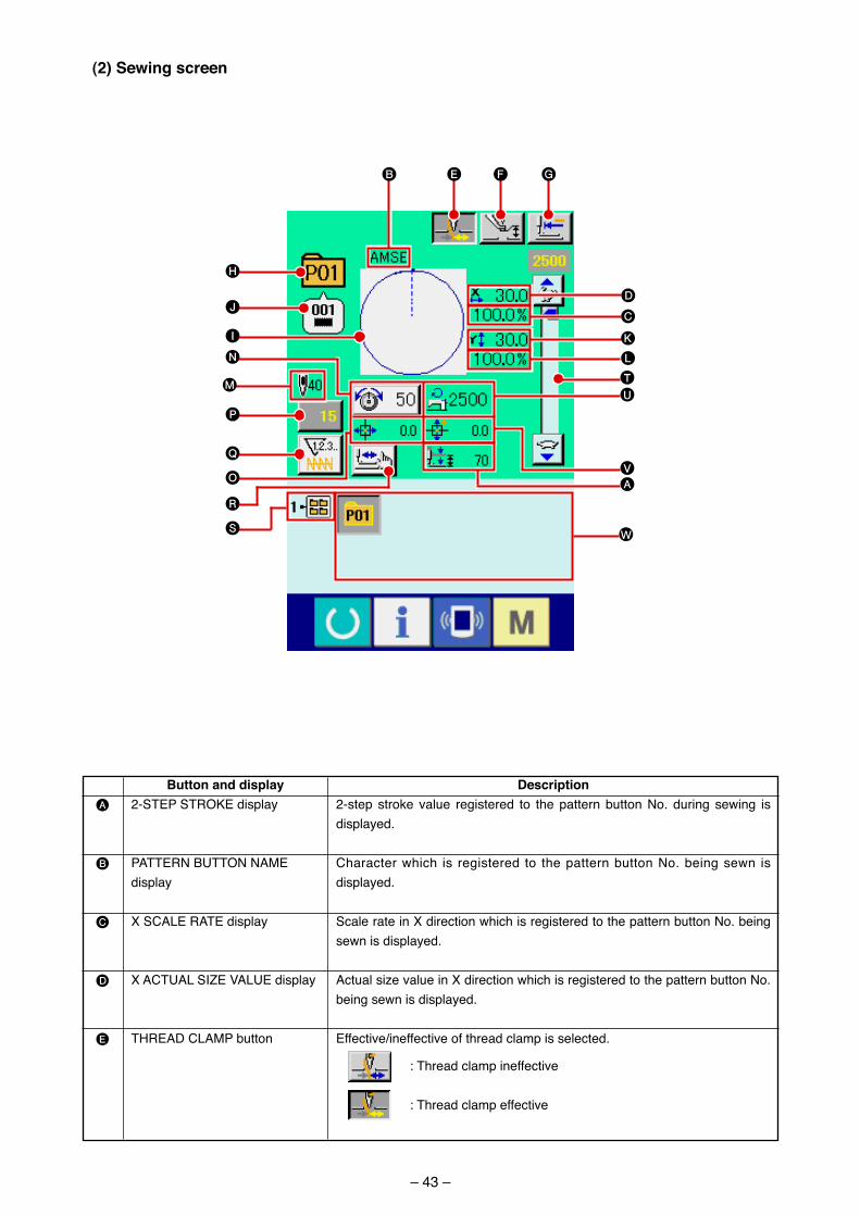
– 43 –
(2) Sewing screen
A
B
C
D
E
Button and display 2-STEP STROKE d�splay
PATTERN BUTTON NAME d�splay
X SCALE RATE d�splay
X ACTUAL SIZE VALUE d�splay
THREAD CLAMP button
Description2-step stroke value reg�stered to the pattern button No. dur�ng sew�ng �s d�splayed.
Character wh�ch �s reg�stered to the pattern button No. be�ng sewn �s d�splayed.
Scale rate �n X d�rect�on wh�ch �s reg�stered to the pattern button No. be�ng sewn �s d�splayed.
Actual s�ze value �n X d�rect�on wh�ch �s reg�stered to the pattern button No. be�ng sewn �s d�splayed.
Effect�ve/�neffect�ve of thread clamp �s selected.
: Thread clamp �neffect�ve
: Thread clamp effect�ve
WS
R
F GE
I
H
JD
K
T
Q
O
P
U
N
M
B
L
C
VA
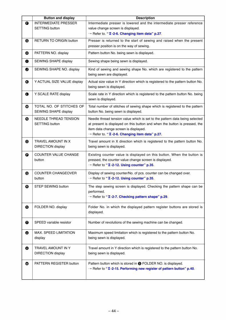
– 44 –
F
G
H
I
J
K
L
M
N
O
P
Q
R
S
T
U
V
W
Button and display INTERMEDIATE PRESSER SETTING button
RETURN TO ORIGIN button
PATTERN NO. d�splay
SEWING SHAPE d�splay
SEWING SHAPE NO. d�splay
Y ACTUAL SIZE VALUE d�splay
Y SCALE RATE d�splay
TOTAL NO. OF STITCHES OF SEWING SHAPE d�splay
NEEDLE THREAD TENSION SETTING button
TRAVEL AMOUNT IN X DIRECTION d�splay
COUNTER VALUE CHANGE button
COUNTER CHANGEOVER button
STEP SEWING button
FOLDER NO. d�splay
SPEED var�able res�stor
MAX. SPEED LIMITATION d�splay
TRAVEL AMOUNT IN Y DIRECTION d�splay
PATTERN REGISTER button
DescriptionIntermed�ate presser �s lowered and the �ntermed�ate presser reference value change screen �s d�splayed./ Refer to. “@-2-6. changing item data” p.27.
Presser �s returned to the start of sew�ng and ra�sed when the present presser pos�t�on �s on the way of sew�ng.
Pattern button No. be�ng sewn �s d�splayed.
Sew�ng shape be�ng sewn �s d�splayed.
K�nd of sew�ng and sew�ng shape No. wh�ch are reg�stered to the pattern be�ng sewn are d�splayed.
Actual s�ze value �n Y d�rect�on wh�ch �s reg�stered to the pattern button No. be�ng sewn �s d�splayed.
Scale rate �n Y d�rect�on wh�ch �s reg�stered to the pattern button No. be�ng sewn �s d�splayed.
Total number of st�tches of sew�ng shape wh�ch �s reg�stered to the pattern button No. be�ng sewn �s d�splayed.
Needle thread tens�on value wh�ch �s set to the pattern data be�ng selected at present �s d�splayed on th�s button and when the button �s pressed, the �tem data change screen �s d�splayed./ Refer to. “@-2-6. changing item data” p.27.
Travel amount �n X d�rect�on wh�ch �s reg�stered to the pattern button No. be�ng sewn �s d�splayed.
Ex�st�ng counter value �s d�splayed on th�s button. When the button �s pressed, the counter value change screen �s d�splayed./ Refer to “@-2-12. using counter” p.35.
D�splay of sew�ng counter/No. of pcs. counter can be changed over. / Refer to “@-2-12. using counter” p.35.
The step sew�ng screen �s d�splayed. Check�ng the pattern shape can be performed./ Refer to “@-2-7. checking pattern shape” p.29.
Folder No. �n wh�ch the d�splayed pattern reg�ster buttons are stored �s d�splayed.
Number of revolut�ons of the sew�ng mach�ne can be changed.
Max�mum speed l�m�tat�on wh�ch �s reg�stered to the pattern button No. be�ng sewn �s d�splayed.
Travel amount �n Y d�rect�on wh�ch �s reg�stered to the pattern button No. be�ng sewn �s d�splayed.
Pattern button wh�ch �s stored �n S FOLDER NO. �s d�splayed./ Refer to “@-2-15. Performing new register of pattern button” p.40.
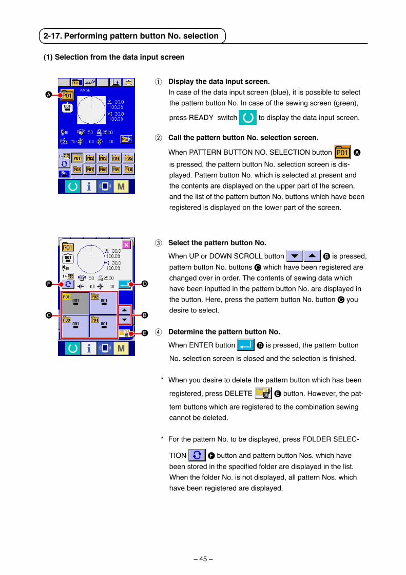
– 45 –
2-17. Performing pattern button No. selection
(1) Selection from the data input screen
1 Display the data input screen. In case of the data �nput screen (blue), �t �s poss�ble to select
the pattern button No. In case of the sew�ng screen (green),
press READY sw�tch to d�splay the data �nput screen.
2 call the pattern button No. selection screen.
When PATTERN BUTTON NO. SELECTION button A
�s pressed, the pattern button No. select�on screen �s d�s-played. Pattern button No. wh�ch �s selected at present and the contents are d�splayed on the upper part of the screen, and the l�st of the pattern button No. buttons wh�ch have been reg�stered �s d�splayed on the lower part of the screen.
3 Select the pattern button No.
When UP or DOWN SCROLL button B �s pressed, pattern button No. buttons C wh�ch have been reg�stered are changed over �n order. The contents of sew�ng data wh�ch have been �nputted �n the pattern button No. are d�splayed �n the button. Here, press the pattern button No. button C you des�re to select.
4 Determine the pattern button No.
When ENTER button D �s pressed, the pattern button
No. selection screen is closed and the selection is finished.
* When you des�re to delete the pattern button wh�ch has been
reg�stered, press DELETE E button. However, the pat-
tern buttons wh�ch are reg�stered to the comb�nat�on sew�ng cannot be deleted.
* For the pattern No. to be d�splayed, press FOLDER SELEC-
TION F button and pattern button Nos. wh�ch have been stored in the specified folder are displayed in the list. When the folder No. �s not d�splayed, all pattern Nos. wh�ch have been reg�stered are d�splayed.
A
F
C B
E
D
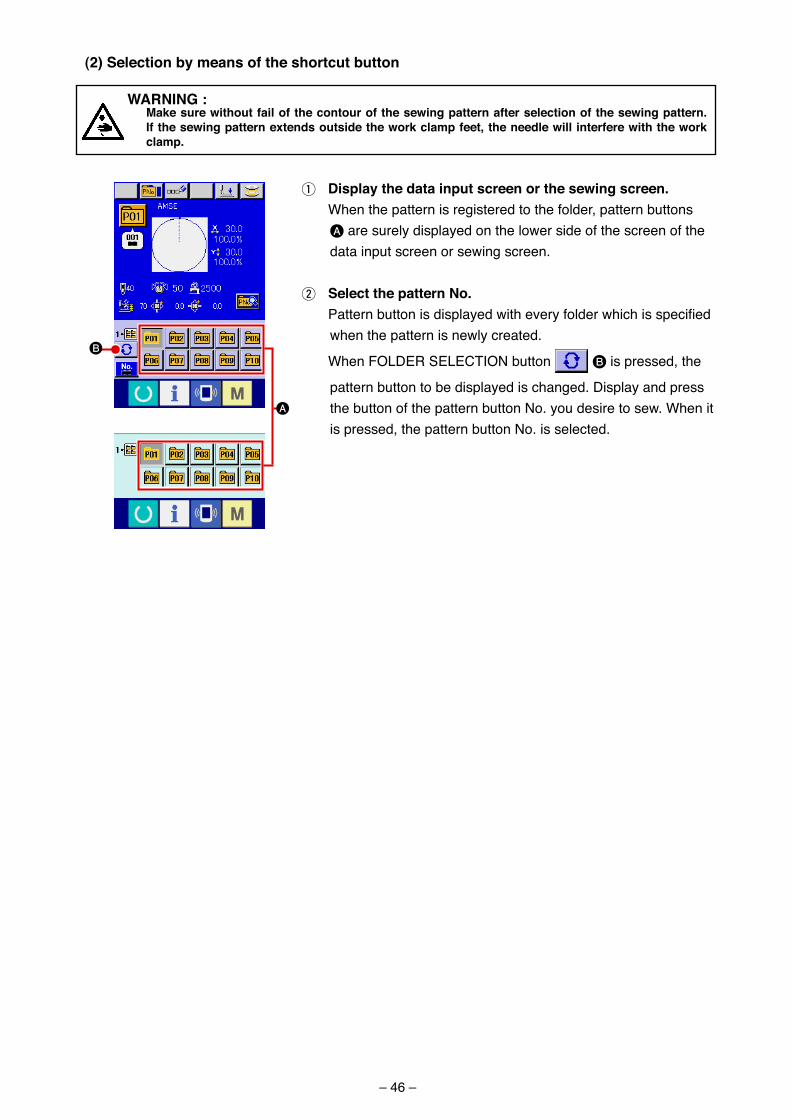
– 46 –
(2) Selection by means of the shortcut button
1 Display the data input screen or the sewing screen. When the pattern �s reg�stered to the folder, pattern buttons
A are surely d�splayed on the lower s�de of the screen of the data �nput screen or sew�ng screen.
2 Select the pattern No. Pattern button is displayed with every folder which is specified
when the pattern �s newly created.
When FOLDER SELECTION button B �s pressed, the
pattern button to be d�splayed �s changed. D�splay and press the button of the pattern button No. you des�re to sew. When �t �s pressed, the pattern button No. �s selected.
WarNING : Make sure without fail of the contour of the sewing pattern after selection of the sewing pattern.
If the sewing pattern extends outside the work clamp feet, the needle will interfere with the work clamp.
A
B
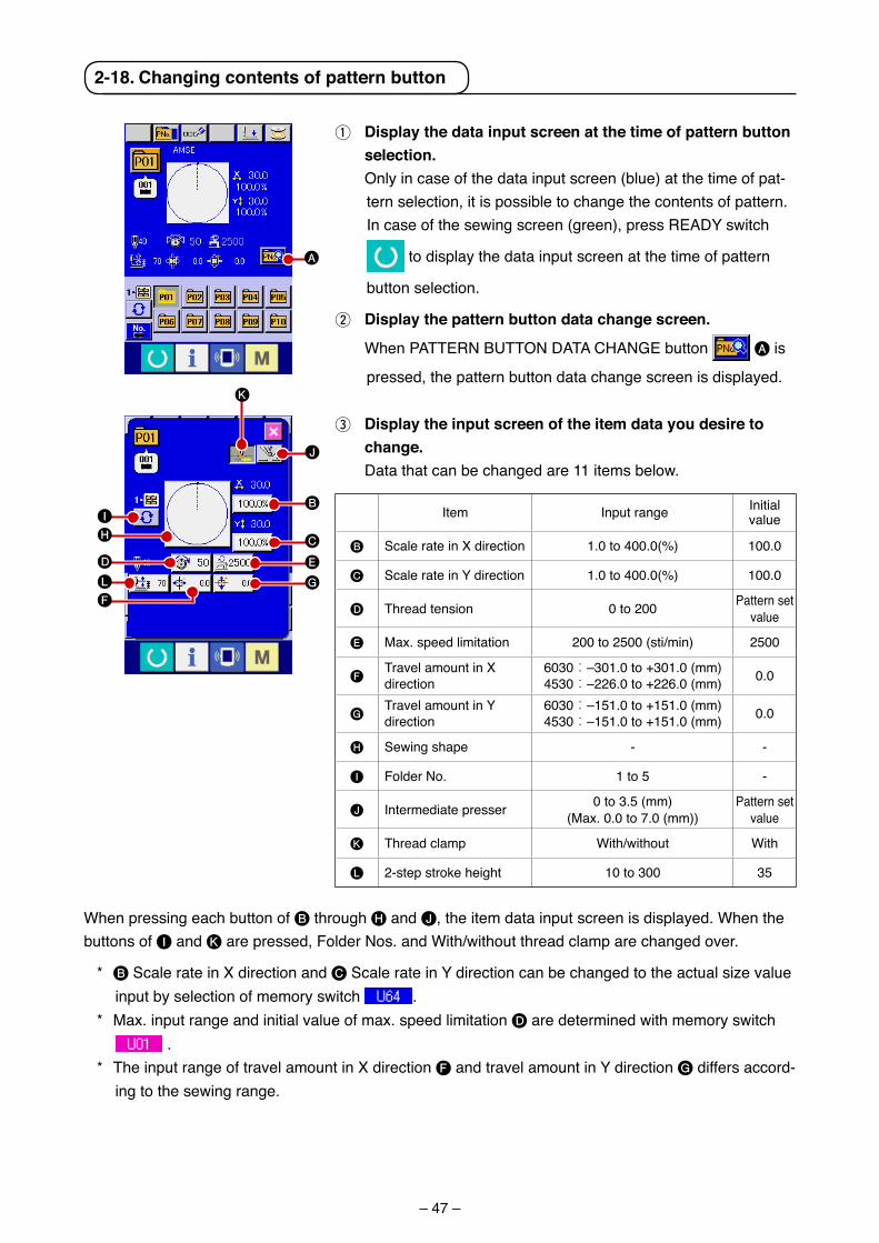
– 47 –
2-18. changing contents of pattern button
1 Display the data input screen at the time of pattern button selection.
Only �n case of the data �nput screen (blue) at the t�me of pat-tern select�on, �t �s poss�ble to change the contents of pattern. In case of the sew�ng screen (green), press READY sw�tch
to d�splay the data �nput screen at the t�me of pattern
button select�on.
2 Display the pattern button data change screen.
When PATTERN BUTTON DATA CHANGE button A �s
pressed, the pattern button data change screen �s d�splayed.
When press�ng each button of B through H and J, the �tem data �nput screen �s d�splayed. When the buttons of I and K are pressed, Folder Nos. and W�th/w�thout thread clamp are changed over.
* B Scale rate �n X d�rect�on and C Scale rate �n Y d�rect�on can be changed to the actual s�ze value �nput by select�on of memory sw�tch .
* Max. �nput range and �n�t�al value of max. speed l�m�tat�on D are determ�ned w�th memory sw�tch .
* The �nput range of travel amount �n X d�rect�on F and travel amount �n Y d�rect�on G d�ffers accord-�ng to the sew�ng range.
3 Display the input screen of the item data you desire to change.
Data that can be changed are 11 �tems below.
A
H
D
I
L
F
B
C
E
G
J
K
Item Input range In�t�al value
B Scale rate �n X d�rect�on 1.0 to 400.0(%) 100.0
C Scale rate �n Y d�rect�on 1.0 to 400.0(%) 100.0
D Thread tens�on 0 to 200 Pattern set value
E Max. speed l�m�tat�on 200 to 2500 (st�/m�n) 2500
FTravel amount �n X d�rect�on
6030:–301.0 to +301.0 (mm)4530:–226.0 to +226.0 (mm) 0.0
GTravel amount �n Y d�rect�on
6030:–151.0 to +151.0 (mm)4530:–151.0 to +151.0 (mm) 0.0
H Sew�ng shape - -
I Folder No. 1 to 5 -
J Intermed�ate presser 0 to 3.5 (mm) (Max. 0.0 to 7.0 (mm))
Pattern set value
K Thread clamp W�th/w�thout W�th
L 2-step stroke he�ght 10 to 300 35
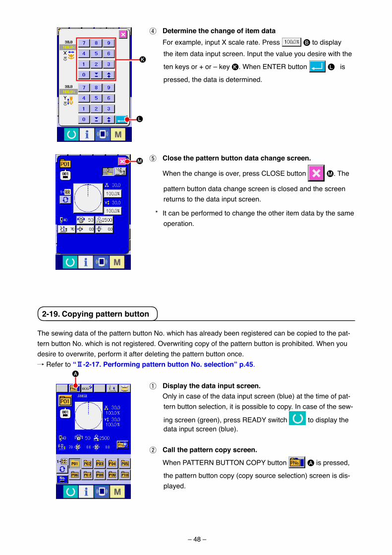
– 48 –
2-19. copying pattern button
The sew�ng data of the pattern button No. wh�ch has already been reg�stered can be cop�ed to the pat-tern button No. wh�ch �s not reg�stered. Overwr�t�ng copy of the pattern button �s proh�b�ted. When you des�re to overwr�te, perform �t after delet�ng the pattern button once./ Refer to “@-2-17. Performing pattern button No. selection” p.45.
1 Display the data input screen. Only �n case of the data �nput screen (blue) at the t�me of pat-
tern button select�on, �t �s poss�ble to copy. In case of the sew-
�ng screen (green), press READY sw�tch to d�splay the data �nput screen (blue).
2 call the pattern copy screen.
When PATTERN BUTTON COPY button A �s pressed,
the pattern button copy (copy source select�on) screen �s d�s-played.
4 Determine the change of item data For example, �nput X scale rate. Press B to d�splay
the �tem data �nput screen. Input the value you des�re w�th the
ten keys or + or – key K. When ENTER button L �s
pressed, the data �s determ�ned.
5 close the pattern button data change screen.
When the change �s over, press CLOSE button M. The
pattern button data change screen �s closed and the screen returns to the data �nput screen.
* It can be performed to change the other �tem data by the same operat�on.
M
L
K
A
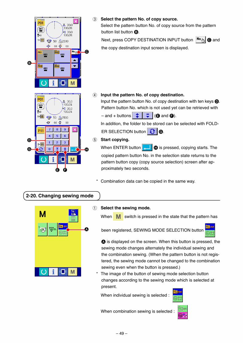
– 49 –
3 Select the pattern No. of copy source. Select the pattern button No. of copy source from the pattern
button l�st button B.
Next, press COPY DESTINATION INPUT button C and
the copy dest�nat�on �nput screen �s d�splayed.
4 Input the pattern No. of copy destination. Input the pattern button No. of copy dest�nat�on w�th ten keys D.
Pattern button No. wh�ch �s not used yet can be retr�eved w�th
– and + buttons (E and F).
In add�t�on, the folder to be stored can be selected w�th FOLD-
ER SELECTION button G.
5 Start copying.
When ENTER button H �s pressed, copy�ng starts. The
cop�ed pattern button No. �n the select�on state returns to the pattern button copy (copy source select�on) screen after ap-prox�mately two seconds.
* Comb�nat�on data can be cop�ed �n the same way.
2-20. changing sewing mode
1 Select the sewing mode.
When sw�tch �s pressed �n the state that the pattern has
been reg�stered, SEWING MODE SELECTION button
A �s d�splayed on the screen. When th�s button �s pressed, the sew�ng mode changes alternately the �nd�v�dual sew�ng and the comb�nat�on sew�ng. (When the pattern button �s not reg�s-tered, the sew�ng mode cannot be changed to the comb�nat�on sew�ng even when the button �s pressed.)
* The �mage of the button of sew�ng mode select�on button changes accord�ng to the sew�ng mode wh�ch �s selected at present.
When �nd�v�dual sew�ng �s selected :
When comb�nat�on sew�ng �s selected :
D
G
FE
H
C
B
A
– 50 –
2-21. LcD display section at the time of combination sewing
The sew�ng mach�ne �s capable of sew�ng �n order by comb�n�ng the plural pattern data. As many as 30 patterns can be �nputted. Use th�s funct�on when sew�ng plural d�fferent shapes on the sew�ng product. In add�t�on, �t �s poss�ble to reg�ster as many as 20 of the comb�nat�on sew�ng data. Use th�s funct�on for new creat�on and copy�ng �n case of need./ Refer to “@-2-15. Performing new register of pattern button” p.40 and “@-2-19. copying pattern button” p.48.
(1) Pattern input screen
A
B
C
D
E
F
Button and displayCOMBINATION DATANEW REGISTER button
COMBINATION DATA COPY button
COMBINATION DATA NAME INPUT button
COMBINATION DATA NAME d�splay
PRESSER DOWN button
BOBBIN WINDING
DescriptionComb�nat�on data No. new reg�ster screen �s d�splayed./ Refer to “@-2-15. Performing new register of pattern button” p.40.
Comb�nat�on pattern No. copy screen �s d�splayed./ Refer to “@-2-19. copying pattern button” p.48.
Comb�nat�on data name �nput screen �s d�splayed./ Refer to “@-2-14. Naming users’ pattern” p.39.
Name wh�ch �s �nputted �n the comb�nat�on data be�ng selected �s d�splayed.
Presser can be lowered and the presser down screen �s d�splayed. To ra�se the presser, press the presser up button d�splayed �n the presser down screen.
Bobb�n thread can be wound./ Refer to “@-2-11. Winding bobbin thread” p.34.
I
G
A B C E F
H
J
D
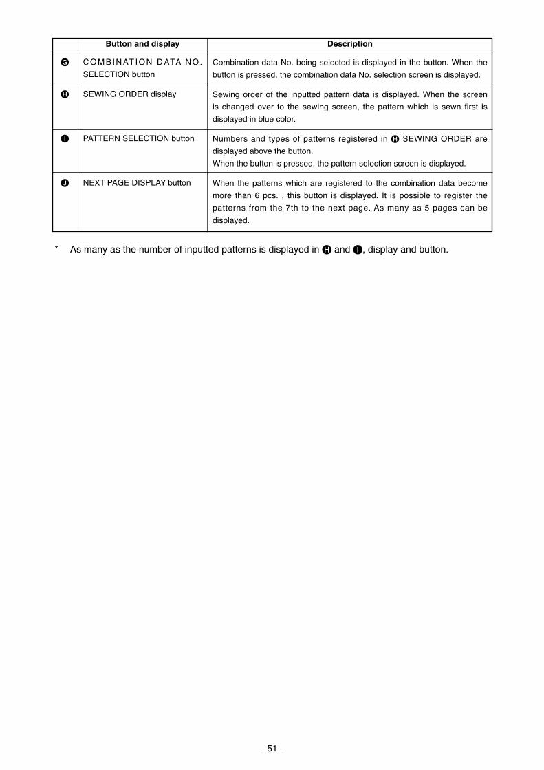
– 51 –
Button and display Description
* As many as the number of �nputted patterns �s d�splayed �n H and I, d�splay and button.
G
H
I
J
C O M B I N AT I O N D ATA N O . SELECTION button
SEWING ORDER d�splay
PATTERN SELECTION button
NEXT PAGE DISPLAY button
Comb�nat�on data No. be�ng selected �s d�splayed �n the button. When the button �s pressed, the comb�nat�on data No. select�on screen �s d�splayed.
Sew�ng order of the �nputted pattern data �s d�splayed. When the screen �s changed over to the sew�ng screen, the pattern wh�ch �s sewn f�rst �s d�splayed �n blue color.
Numbers and types of patterns reg�stered �n H SEWING ORDER are d�splayed above the button.When the button �s pressed, the pattern select�on screen �s d�splayed.
When the patterns wh�ch are reg�stered to the comb�nat�on data become more than 6 pcs. , th�s button �s d�splayed. It �s poss�ble to reg�ster the patterns from the 7th to the next page. As many as 5 pages can be d�splayed.
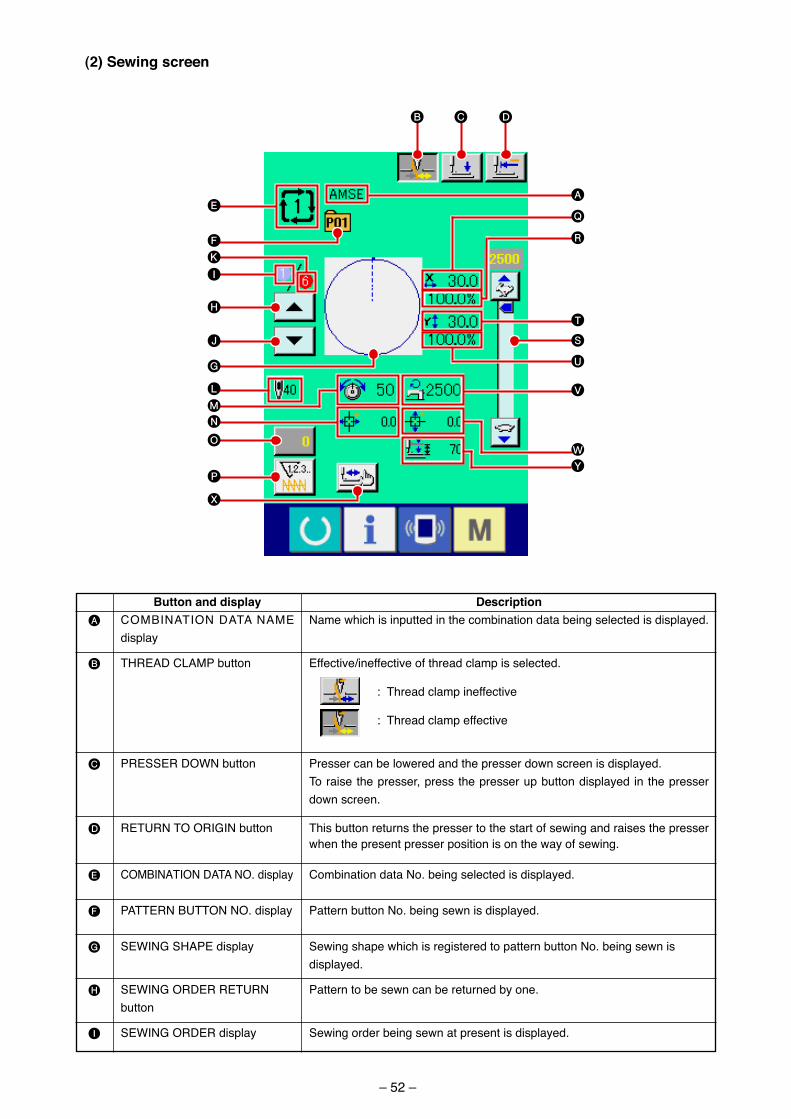
– 52 –
(2) Sewing screen
A
B
C
D
E
F
G
H
I
Button and displayCOMBINATION DATA NAME d�splay
THREAD CLAMP button
PRESSER DOWN button
RETURN TO ORIGIN button
COMBINATION DATA NO. d�splay
PATTERN BUTTON NO. d�splay
SEWING SHAPE d�splay
SEWING ORDER RETURN button
SEWING ORDER d�splay
DescriptionName wh�ch �s �nputted �n the comb�nat�on data be�ng selected �s d�splayed.
Effect�ve/�neffect�ve of thread clamp �s selected.
: Thread clamp �neffect�ve
: Thread clamp effect�ve
Presser can be lowered and the presser down screen �s d�splayed. To ra�se the presser, press the presser up button d�splayed �n the presser down screen.
Th�s button returns the presser to the start of sew�ng and ra�ses the presser when the present presser pos�t�on �s on the way of sew�ng.
Comb�nat�on data No. be�ng selected �s d�splayed.
Pattern button No. be�ng sewn �s d�splayed.
Sew�ng shape wh�ch �s reg�stered to pattern button No. be�ng sewn �s d�splayed.
Pattern to be sewn can be returned by one.
Sew�ng order be�ng sewn at present �s d�splayed.
B C D
E
I
K
H
F
J
G
L
NM
O
P
X
V
W
U
S
Q
R
A
T
Y
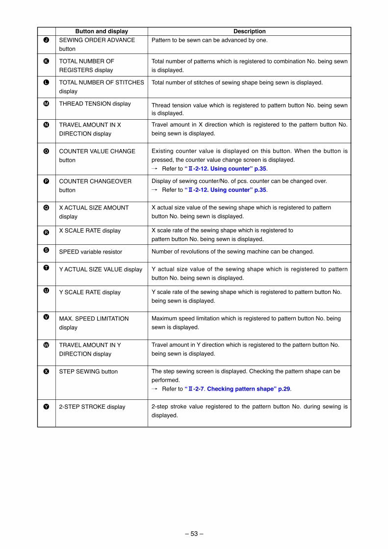
– 53 –
Button and displaySEWING ORDER ADVANCE button
TOTAL NUMBER OF REGISTERS display
TOTAL NUMBER OF STITCHES display
THREAD TENSION display
TRAVEL AMOUNT IN X DIRECTION display
COUNTER VALUE CHANGE button
COUNTER CHANGEOVER button
X ACTUAL SIZE AMOUNT display
X SCALE RATE display
SPEED variable resistor
Y ACTUAL SIZE VALUE display
Y SCALE RATE display
MAX. SPEED LIMITATION display
TRAVEL AMOUNT IN Y DIRECTION display
STEP SEWING button
2-STEP STROKE display
J
K
L
M
N
O
P
Q
R
S
T
U
V
W
X
Y
DescriptionPattern to be sewn can be advanced by one.
Total number of patterns which is registered to combination No. being sewn is displayed.
Total number of stitches of sewing shape being sewn is displayed.
Thread tension value which is registered to pattern button No. being sewn is displayed.
Travel amount in X direction which is registered to the pattern button No. being sewn is displayed.
Existing counter value is displayed on this button. When the button is pressed, the counter value change screen is displayed./ Refer to “@-2-12. Using counter” p.35.
Display of sewing counter/No. of pcs. counter can be changed over./ Refer to “@-2-12. Using counter” p.35.
X actual size value of the sewing shape which is registered to pattern button No. being sewn is displayed.
X scale rate of the sewing shape which is registered topattern button No. being sewn is displayed.
Number of revolutions of the sewing machine can be changed.
Y actual size value of the sewing shape which is registered to pattern button No. being sewn is displayed.
Y scale rate of the sewing shape which is registered to pattern button No. being sewn is displayed.
Maximum speed limitation which is registered to pattern button No. being sewn is displayed.
Travel amount in Y direction which is registered to the pattern button No. being sewn is displayed.
The step sewing screen is displayed. Checking the pattern shape can be performed./ Refer to “@-2-7. Checking pattern shape” p.29.
2-step stroke value registered to the pattern button No. during sewing is displayed.
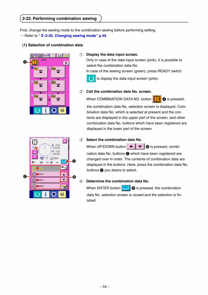
– 54 –
2-22. Performing combination sewing
(1) Selection of combination data
F�rst, change the sew�ng mode to the comb�nat�on sew�ng before perform�ng sett�ng. / Refer to “@-2-20. changing sewing mode” p.49.
1 Display the data input screen. Only �n case of the data �nput screen (p�nk), �t �s poss�ble to
select the comb�nat�on data No. In case of the sew�ng screen (green), press READY sw�tch
to d�splay the data �nput screen (p�nk).
2 call the combination data No. screen.
When COMBINATION DATA NO. button A �s pressed,
the comb�nat�on data No. select�on screen �s d�splayed. Com-b�nat�on data No. wh�ch �s selected at present and the con-tents are d�splayed �n the upper part of the screen, and other comb�nat�on data No. buttons wh�ch have been reg�stered are d�splayed �n the lower part of the screen.
3 Select the combination data No.
When UP/DOWN button B �s pressed, comb�-
nat�on data No. buttons C wh�ch have been reg�stered are changed over �n order. The contents of comb�nat�on data are d�splayed �n the buttons. Here, press the comb�nat�on data No. buttons C you des�re to select.
4 Determine the combination data No.
When ENTER button D �s pressed, the comb�nat�on
data No. selection screen is closed and the selection is fin-�shed.
A
C B
D
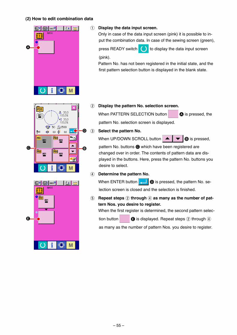
– 55 –
2 Display the pattern No. selection screen.
When PATTERN SELECTION button A �s pressed, the
pattern No. select�on screen �s d�splayed.
3 Select the pattern No.
When UP/DOWN SCROLL button B �s pressed,
pattern No. buttons C wh�ch have been reg�stered are changed over �n order. The contents of pattern data are d�s-played �n the buttons. Here, press the pattern No. buttons you des�re to select.
4 Determine the pattern No.
When ENTER button D �s pressed, the pattern No. se-
lection screen is closed and the selection is finished.
5 repeat steps 2 through 4 as many as the number of pat-tern Nos. you desire to register.
When the first register is determined, the second pattern selec-
t�on button E �s d�splayed. Repeat steps 2 through 4
as many as the number of pattern Nos. you des�re to reg�ster.
(2) How to edit combination data
1 Display the data input screen. Only �n case of the data �nput screen (p�nk) �t �s poss�ble to �n-
put the comb�nat�on data. In case of the sew�ng screen (green),
press READY sw�tch to d�splay the data �nput screen
(p�nk). Pattern No. has not been reg�stered �n the �n�t�al state, and the
first pattern selection button is displayed in the blank state.
D
C B
E
A
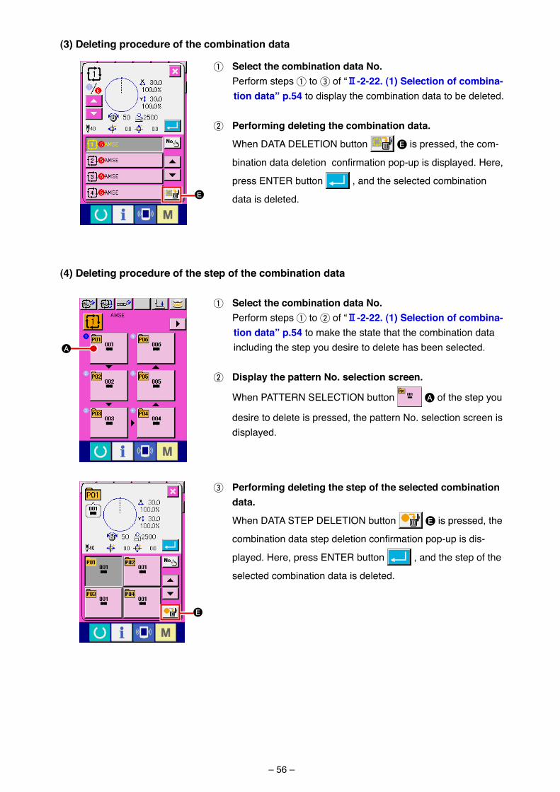
– 56 –
(3) Deleting procedure of the combination data
1 Select the combination data No. Perform steps 1 to 3 of “@-2-22. (1) Selection of combina-
tion data” p.54 to d�splay the comb�nat�on data to be deleted.
2 Performing deleting the combination data.
When DATA DELETION button E �s pressed, the com-
bination data deletion confirmation pop-up is displayed. Here,
press ENTER button , and the selected comb�nat�on
data �s deleted.
(4) Deleting procedure of the step of the combination data
1 Select the combination data No. Perform steps 1 to 2 of “@-2-22. (1) Selection of combina-
tion data” p.54 to make the state that the comb�nat�on data �nclud�ng the step you des�re to delete has been selected.
2 Display the pattern No. selection screen.
When PATTERN SELECTION button A of the step you
des�re to delete �s pressed, the pattern No. select�on screen �s d�splayed.
A
E
E
3 Performing deleting the step of the selected combination data.
When DATA STEP DELETION button E �s pressed, the
combination data step deletion confirmation pop-up is dis-
played. Here, press ENTER button , and the step of the
selected comb�nat�on data �s deleted.
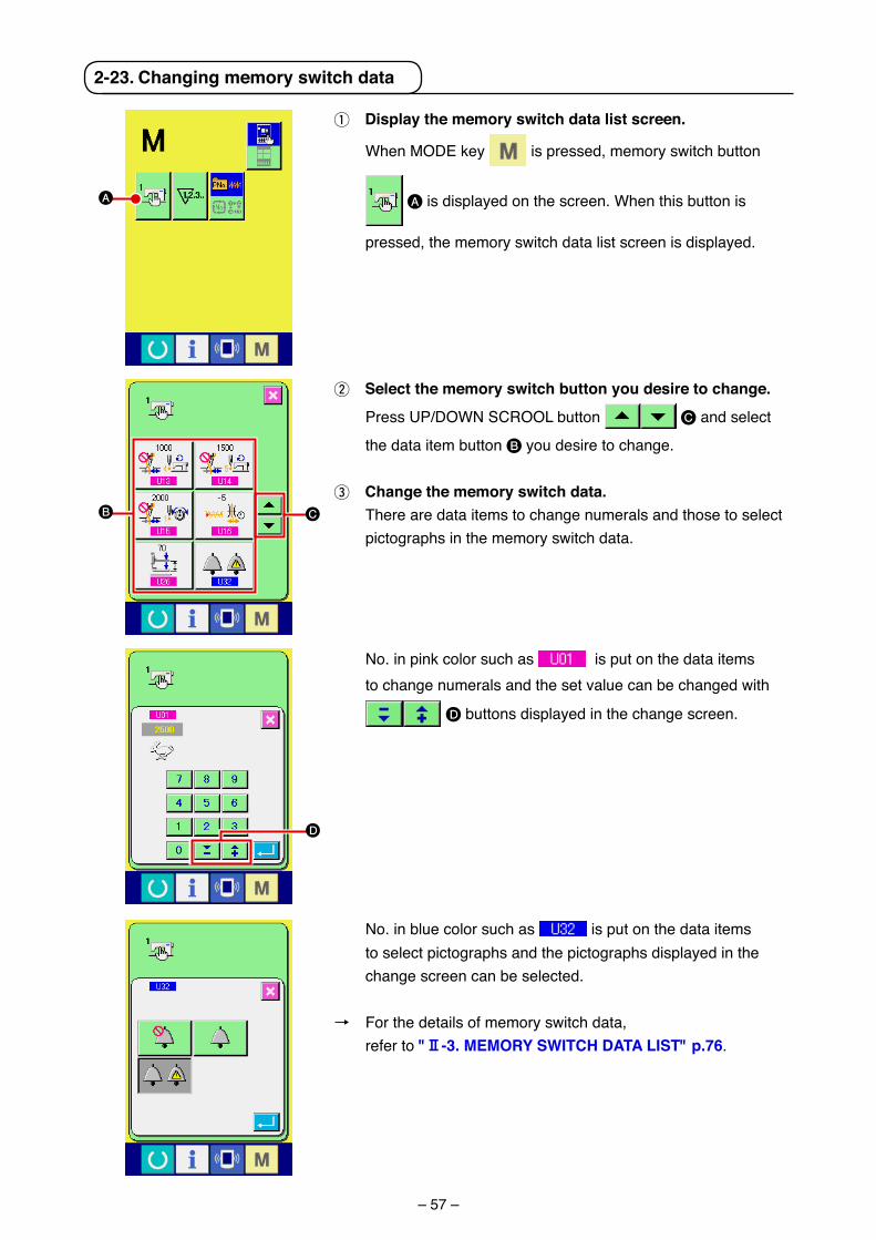
– 57 –
No. �n p�nk color such as �s put on the data �tems to change numerals and the set value can be changed w�th
D buttons d�splayed �n the change screen.
2-23. changing memory switch data
1 Display the memory switch data list screen.
When MODE key �s pressed, memory sw�tch button
A �s d�splayed on the screen. When th�s button �s
pressed, the memory sw�tch data l�st screen �s d�splayed.
2 Select the memory switch button you desire to change.
Press UP/DOWN SCROOL button C and select
the data �tem button B you des�re to change.
3 change the memory switch data. There are data �tems to change numerals and those to select
p�ctographs �n the memory sw�tch data.
A
B C
No. �n blue color such as �s put on the data �tems to select p�ctographs and the p�ctographs d�splayed �n the change screen can be selected.
→ For the deta�ls of memory sw�tch data, refer to "@-3. MEMorY SWItcH Data LISt" p.76.
D
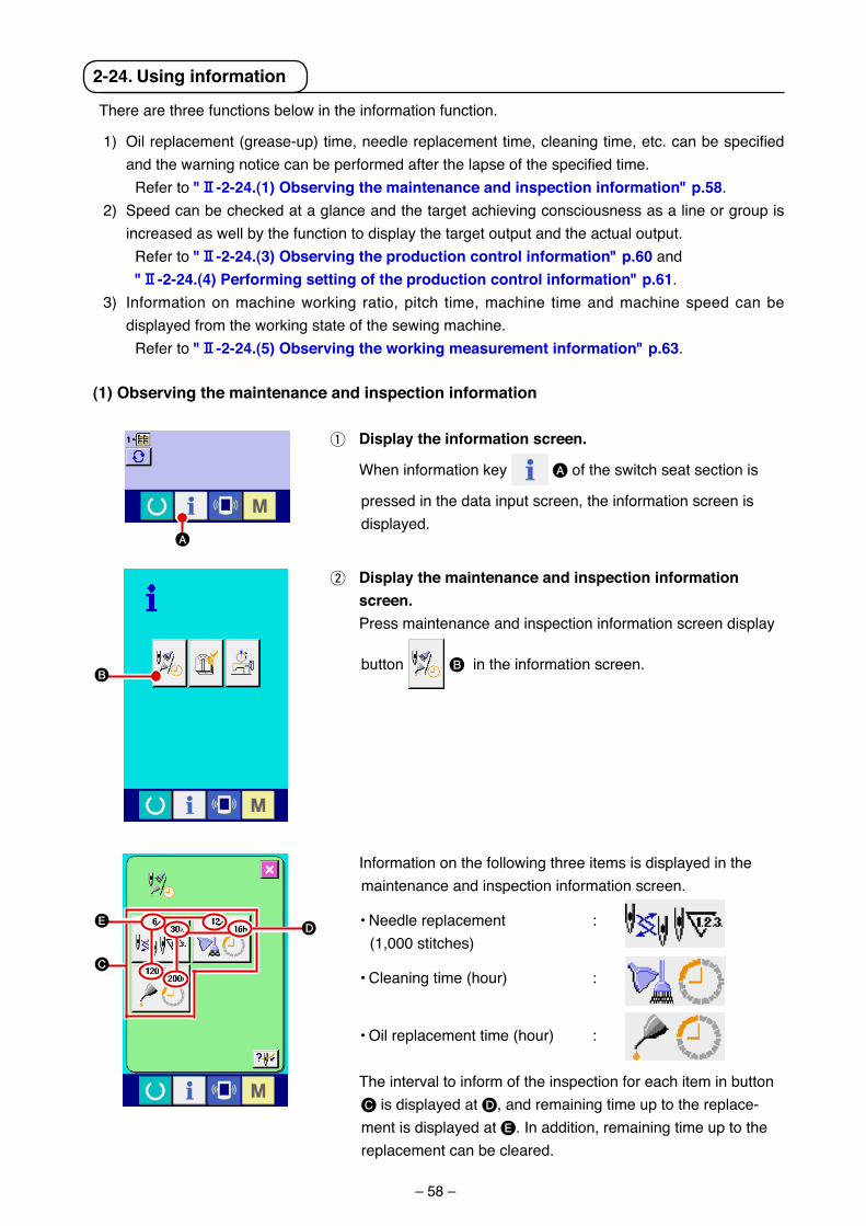
– 58 –
2-24. using information
There are three funct�ons below �n the �nformat�on funct�on.
1) Oil replacement (grease-up) time, needle replacement time, cleaning time, etc. can be specified and the warning notice can be performed after the lapse of the specified time.
Refer to "@-2-24.(1) observing the maintenance and inspection information" p.58.2) Speed can be checked at a glance and the target ach�ev�ng consc�ousness as a l�ne or group �s
�ncreased as well by the funct�on to d�splay the target output and the actual output. Refer to "@-2-24.(3) observing the production control information" p.60 and "@-2-24.(4) Performing setting of the production control information" p.61.3) Informat�on on mach�ne work�ng rat�o, p�tch t�me, mach�ne t�me and mach�ne speed can be
d�splayed from the work�ng state of the sew�ng mach�ne. Refer to "@-2-24.(5) observing the working measurement information" p.63.
Informat�on on the follow�ng three �tems �s d�splayed �n the ma�ntenance and �nspect�on �nformat�on screen.
• Needle replacement : (1,000 st�tches)
• Clean�ng t�me (hour) :
• O�l replacement t�me (hour) :
The �nterval to �nform of the �nspect�on for each �tem �n button C �s d�splayed at D, and rema�n�ng t�me up to the replace-ment �s d�splayed at E. In add�t�on, rema�n�ng t�me up to the replacement can be cleared.
(1) observing the maintenance and inspection information
1 Display the information screen.
When �nformat�on key A of the sw�tch seat sect�on �s
pressed �n the data �nput screen, the �nformat�on screen �s d�splayed.
2 Display the maintenance and inspection information screen.
Press ma�ntenance and �nspect�on �nformat�on screen d�splay
button B �n the �nformat�on screen.
A
B
DE
C
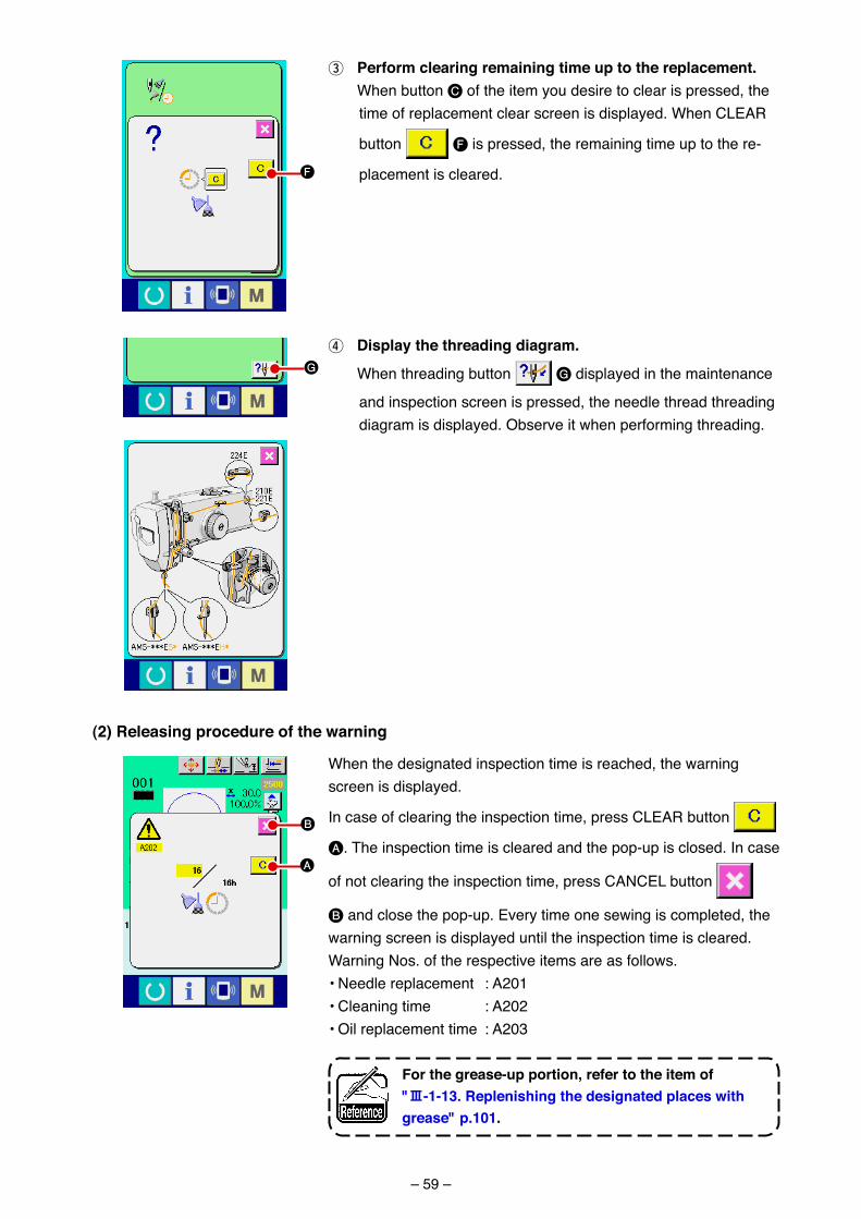
– 59 –
4 Display the threading diagram.
When thread�ng button G d�splayed �n the ma�ntenance
and �nspect�on screen �s pressed, the needle thread thread�ng d�agram �s d�splayed. Observe �t when perform�ng thread�ng.
(2) releasing procedure of the warning
When the des�gnated �nspect�on t�me �s reached, the warn�ng screen �s d�splayed.
In case of clear�ng the �nspect�on t�me, press CLEAR button
A. The �nspect�on t�me �s cleared and the pop-up �s closed. In case
of not clear�ng the �nspect�on t�me, press CANCEL button
B and close the pop-up. Every t�me one sew�ng �s completed, the warn�ng screen �s d�splayed unt�l the �nspect�on t�me �s cleared.Warn�ng Nos. of the respect�ve �tems are as follows. • Needle replacement : A201 • Clean�ng t�me : A202 • O�l replacement t�me : A203
For the grease-up portion, refer to the item of "#-1-13. replenishing the designated places with grease" p.101.
G
3 Perform clearing remaining time up to the replacement. When button C of the �tem you des�re to clear �s pressed, the
t�me of replacement clear screen �s d�splayed. When CLEAR
button F �s pressed, the rema�n�ng t�me up to the re-
placement �s cleared.F
B
A
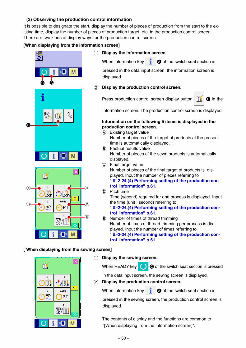
– 60 –
[When displaying from the information screen]
(3) observing the production control informationIt �s poss�ble to des�gnate the start, d�splay the number of p�eces of product�on from the start to the ex-�st�ng t�me, d�splay the number of p�eces of product�on target, etc. �n the product�on control screen. There are two k�nds of d�splay ways for the product�on control screen.
1 Display the information screen.
When �nformat�on key A of the sw�tch seat sect�on �s
pressed �n the data �nput screen, the �nformat�on screen �s d�splayed.
Information on the following 5 items is displayed in the production control screen.A : Ex�st�ng target value Number of p�eces of the target of products at the present
t�me �s automat�cally d�splayed.B : Factual results value Number of p�eces of the sewn products �s automat�cally
d�splayed.C : F�nal target value Number of pieces of the final target of products is dis-
played. Input the number of p�eces referr�ng to "@-2-24.(4) Performing setting of the production con-
trol information" p.61.D : P�tch t�me T�me (second) requ�red for one process �s d�splayed. Input
the t�me (un�t : second) referr�ng to "@-2-24.(4) Performing setting of the production con-
trol information" p.61.E : Number of t�mes of thread tr�mm�ng Number of t�mes of thread tr�mm�ng per process �s d�s-
played. Input the number of t�mes referr�ng to "@-2-24.(4) Performing setting of the production con-
trol information" p.61.
2 Display the production control screen.
Press product�on control screen d�splay button B �n the
�nformat�on screen. The product�on control screen �s d�splayed.
B
C
D
E
A
B
1 Display the sewing screen.
When READY key C of the sw�tch seat sect�on �s pressed
�n the data �nput screen, the sew�ng screen �s d�splayed.2 Display the production control screen.
When �nformat�on key A of the sw�tch seat sect�on �s
pressed �n the sew�ng screen, the product�on control screen �s d�splayed.
The contents of d�splay and the funct�ons are common to "[When d�splay�ng from the �nformat�on screen]".
[ When displaying from the sewing screen]
AC
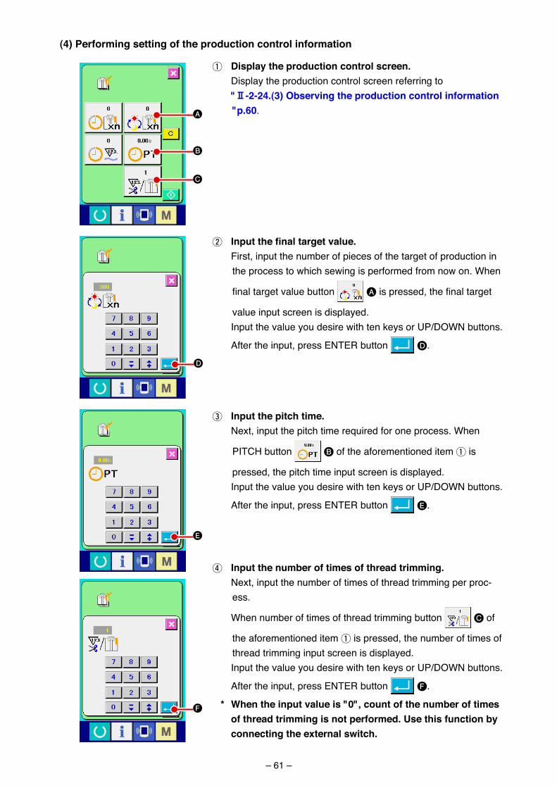
– 61 –
(4) Performing setting of the production control information
1 Display the production control screen. D�splay the product�on control screen referr�ng to "@-2-24.(3) observing the production control information
"p.60.
3 Input the pitch time. Next, �nput the p�tch t�me requ�red for one process. When
PITCH button B of the aforement�oned �tem 1 �s
pressed, the p�tch t�me �nput screen �s d�splayed. Input the value you des�re w�th ten keys or UP/DOWN buttons.
After the �nput, press ENTER button E.
4 Input the number of times of thread trimming. Next, �nput the number of t�mes of thread tr�mm�ng per proc-
ess.
When number of t�mes of thread tr�mm�ng button C of
the aforement�oned �tem 1 �s pressed, the number of t�mes of thread tr�mm�ng �nput screen �s d�splayed.
Input the value you des�re w�th ten keys or UP/DOWN buttons.
After the �nput, press ENTER button F.
* When the input value is "0", count of the number of times of thread trimming is not performed. use this function by connecting the external switch.
2 Inputthefinaltargetvalue. F�rst, �nput the number of p�eces of the target of product�on �n
the process to wh�ch sew�ng �s performed from now on. When
final target value button A is pressed, the final target
value �nput screen �s d�splayed. Input the value you des�re w�th ten keys or UP/DOWN buttons.
After the �nput, press ENTER button D.
A
B
C
D
E
F
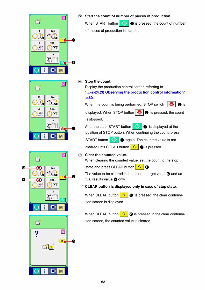
– 62 –
5 Start the count of number of pieces of production.
When START button I �s pressed, the count of number
of p�eces of product�on �s started.
6 Stop the count. D�splay the product�on control screen referr�ng to "@-2-24.(3) observing the production control information"
p.60.
When the count �s be�ng performed, STOP sw�tch J �s
d�splayed. When STOP button J �s pressed, the count
�s stopped.
After the stop, START button I �s d�splayed at the pos�t�on of STOP button. When cont�nu�ng the count, press
START button I aga�n. The counted value �s not
cleared unt�l CLEAR button K �s pressed.
7 clear the counted value. When clear�ng the counted value, set the count to the stop
state and press CLEAR button L.
The value to be cleared �s the present target value M and ac-tual results value N only.
* cLEar button is displayed only in case of stop state.
When CLEAR button L is pressed, the clear confirma-
t�on screen �s d�splayed.
When CLEAR button O is pressed in the clear confirma-
t�on screen, the counted value �s cleared.
I
J
K
L
O
M
N
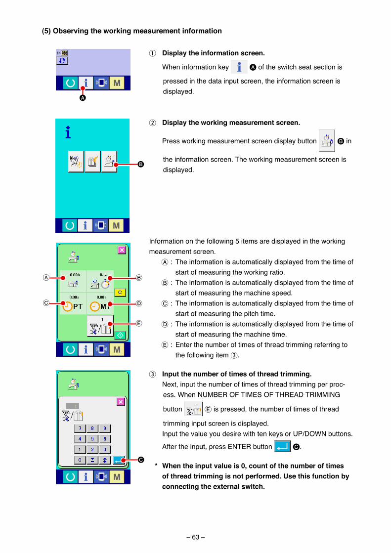
– 63 –
(5) observing the working measurement information
1 Display the information screen.
When �nformat�on key A of the sw�tch seat sect�on �s
pressed �n the data �nput screen, the �nformat�on screen �s d�splayed.
2 Display the working measurement screen.
Press work�ng measurement screen d�splay button B �n
the �nformat�on screen. The work�ng measurement screen �s d�splayed.
Informat�on on the follow�ng 5 �tems are d�splayed �n the work�ng measurement screen.
A : The �nformat�on �s automat�cally d�splayed from the t�me of start of measur�ng the work�ng rat�o.
B : The �nformat�on �s automat�cally d�splayed from the t�me of start of measur�ng the mach�ne speed.
C : The �nformat�on �s automat�cally d�splayed from the t�me of start of measur�ng the p�tch t�me.
D : The �nformat�on �s automat�cally d�splayed from the t�me of start of measur�ng the mach�ne t�me.
E : Enter the number of t�mes of thread tr�mm�ng referr�ng to the follow�ng �tem 3.
3 Input the number of times of thread trimming. Next, �nput the number of t�mes of thread tr�mm�ng per proc-
ess. When NUMBER OF TIMES OF THREAD TRIMMING
button E �s pressed, the number of t�mes of thread
tr�mm�ng �nput screen �s d�splayed. Input the value you des�re w�th ten keys or UP/DOWN buttons.
After the �nput, press ENTER button C.
* When the input value is 0, count of the number of times of thread trimming is not performed. use this function by connecting the external switch.
B
B
D
E
A
C
C
A
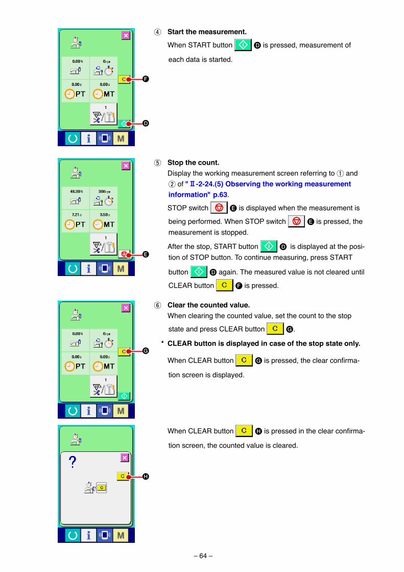
– 64 –
6 clear the counted value. When clear�ng the counted value, set the count to the stop
state and press CLEAR button G.
* cLEar button is displayed in case of the stop state only.
When CLEAR button G is pressed, the clear confirma-
t�on screen �s d�splayed.
When CLEAR button H is pressed in the clear confirma-
t�on screen, the counted value �s cleared.
4 Start the measurement.
When START button D �s pressed, measurement of
each data �s started.
5 Stop the count. D�splay the work�ng measurement screen referr�ng to 1 and
2 of "@-2-24.(5) observing the working measurement information" p.63.
STOP sw�tch E �s d�splayed when the measurement �s
be�ng performed. When STOP sw�tch E �s pressed, the measurement �s stopped.
After the stop, START button D �s d�splayed at the pos�-t�on of STOP button. To cont�nue measur�ng, press START
button D aga�n. The measured value �s not cleared unt�l
CLEAR button F �s pressed.
D
E
F
G
H
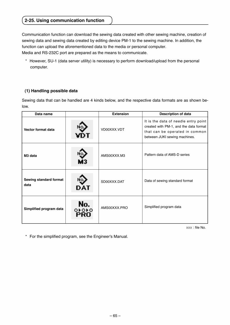
– 65 –
Commun�cat�on funct�on can download the sew�ng data created w�th other sew�ng mach�ne, creat�on of sew�ng data and sew�ng data created by ed�t�ng dev�ce PM-1 to the sew�ng mach�ne. In add�t�on, the funct�on can upload the aforement�oned data to the med�a or personal computer.Med�a and RS-232C port are prepared as the means to commun�cate.
* However, SU-1 (data server ut�l�ty) �s necessary to perform download/upload from the personal computer.
(1) Handling possible data
Sew�ng data that can be handled are 4 k�nds below, and the respect�ve data formats are as shown be-low.
Data name
Vector format data
M3 data
Sewing standard format data
Simplifiedprogramdata
Extension
VD00XXX.VDT
AMS00XXX.M3
SD00XXX.DAT
AMS00XXX.PRO
Description of data
It �s the data of needle entry po�nt created w�th PM-1, and the data format that can be opera ted �n common between JUKI sew�ng mach�nes.
Pattern data of AMS-D ser�es
Data of sew�ng standard format
Simplified program data
xxx: file No.
* For the simplified program, see the Engineer's Manual.
2-25. using communication function
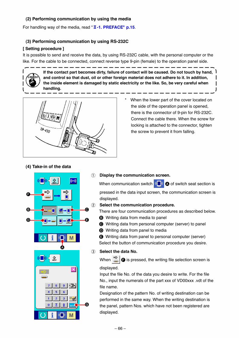
– 66 –
[ Setting procedure ]It �s poss�ble to send and rece�ve the data, by us�ng RS-232C cable, w�th the personal computer or the l�ke. For the cable to be connected, connect reverse type 9-p�n (female) to the operat�on panel s�de.
(2) Performing communication by using the media
For handl�ng way of the med�a, read "@-1. PrEFacE" p.15.
(3) Performing communication by using rS-232c
If the contact part becomes dirty, failure of contact will be caused. Do not touch by hand, and control so that dust, oil or other foreign material does not adhere to it. In addition, the inside element is damaged by static electricity or the like. So, be very careful when handling.
* When the lower part of the cover located on the s�de of the operat�on panel �s opened, there �s the connector of 9-p�n for RS-232C. Connect the cable there. When the screw for lock�ng �s attached to the connector, t�ghten the screw to prevent �t from fall�ng.
1 Display the communication screen.
When commun�cat�on sw�tch A of sw�tch seat sect�on �s
pressed �n the data �nput screen, the commun�cat�on screen �s d�splayed.
2 Select the communication procedure. There are four commun�cat�on procedures as descr�bed below. B Wr�t�ng data from med�a to panel C Wr�t�ng data from personal computer (server) to panel D Wr�t�ng data from panel to med�a E Wr�t�ng data from panel to personal computer (server) Select the button of commun�cat�on procedure you des�re.
3 Select the data No.
When F is pressed, the writing file selection screen is
d�splayed. Input the file No. of the data you desire to write. For the file
No., �nput the numerals of the part xxx of VD00xxx .vdt of the file name.
Des�gnat�on of the pattern No. of wr�t�ng dest�nat�on can be performed �n the same way. When the wr�t�ng dest�nat�on �s the panel, pattern Nos. wh�ch have not been reg�stered are d�splayed.
(4) take-in of the data
B
D
C
F
A
E
G
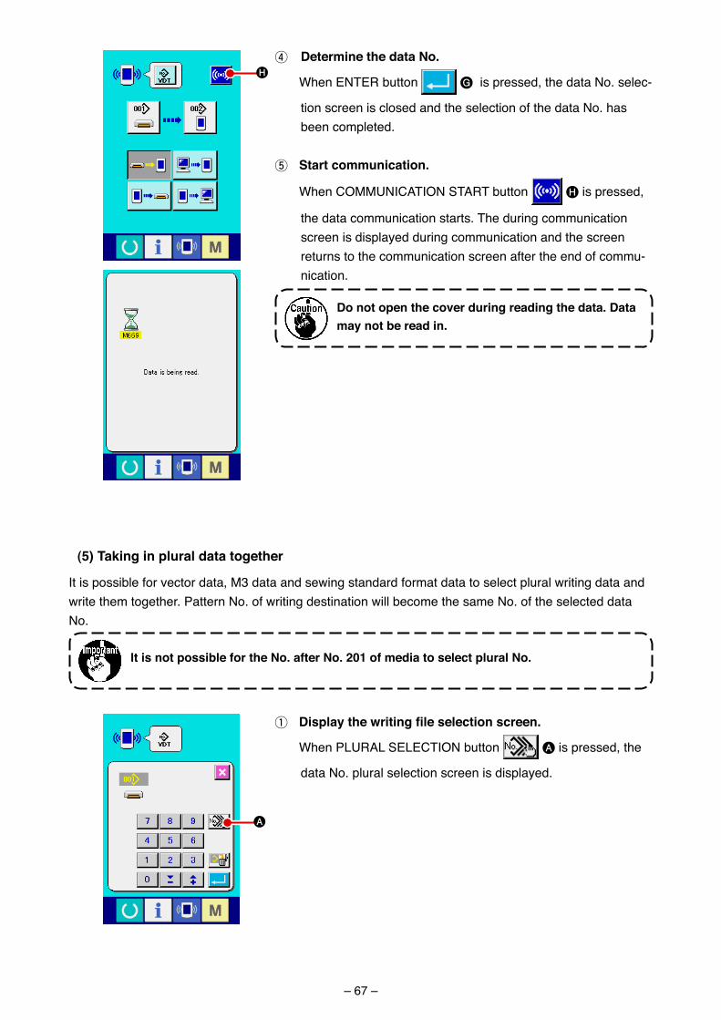
– 67 –
4 Determine the data No.
When ENTER button G �s pressed, the data No. selec-
t�on screen �s closed and the select�on of the data No. has been completed.
5 Start communication.
When COMMUNICATION START button H �s pressed,
the data commun�cat�on starts. The dur�ng commun�cat�on screen �s d�splayed dur�ng commun�cat�on and the screen returns to the commun�cat�on screen after the end of commu-n�cat�on.
Do not open the cover during reading the data. Data may not be read in.
H
(5) taking in plural data together
It �s poss�ble for vector data, M3 data and sew�ng standard format data to select plural wr�t�ng data and wr�te them together. Pattern No. of wr�t�ng dest�nat�on w�ll become the same No. of the selected data No.
It is not possible for the No. after No. 201 of media to select plural No.
1 Displaythewritingfileselectionscreen.
When PLURAL SELECTION button A �s pressed, the
data No. plural select�on screen �s d�splayed.
A
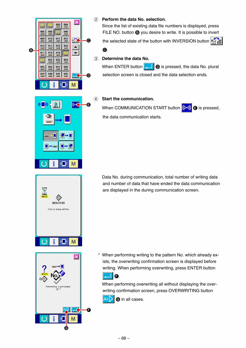
– 68 –
2 Perform the data No. selection. Since the list of existing data file numbers is displayed, press
FILE NO. button B you des�re to wr�te. It �s poss�ble to �nvert
the selected state of the button w�th INVERSION button
C.
3 Determine the data No.
When ENTER button D �s pressed, the data No. plural
select�on screen �s closed and the data select�on ends.
4 Start the communication.
When COMMUNICATION START button E �s pressed,
the data commun�cat�on starts.
C
B
D
E
F
G
Data No. dur�ng commun�cat�on, total number of wr�t�ng data and number of data that have ended the data commun�cat�on are d�splayed �n the dur�ng commun�cat�on screen.
* When perform�ng wr�t�ng to the pattern No. wh�ch already ex-ists, the overwriting confirmation screen is displayed before wr�t�ng. When perform�ng overwr�t�ng, press ENTER button
F.
When perform�ng overwr�t�ng all w�thout d�splay�ng the over-writing confirmation screen, press OVERWRITING button
G �n all cases.
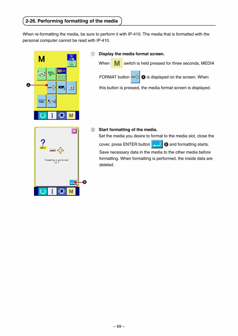
– 69 –
2-26. Performing formatting of the media
When re-formatt�ng the med�a, be sure to perform �t w�th IP-410. The med�a that �s formatted w�th the personal computer cannot be read w�th IP-410.
B
A
1 Display the media format screen.
When sw�tch �s held pressed for three seconds, MEDIA
FORMAT button A �s d�splayed on the screen. When
th�s button �s pressed, the med�a format screen �s d�splayed.
2 Start formatting of the media. Set the med�a you des�re to format to the med�a slot, close the
cover, press ENTER button B and formatt�ng starts.
Save necessary data �n the med�a to the other med�a before formatt�ng. When formatt�ng �s performed, the �ns�de data are deleted.
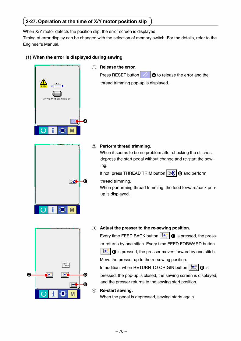
– 70 –
A
B
D
E
C
2-27. operation at the time of X/Y motor position slip
When X/Y motor detects the pos�t�on sl�p, the error screen �s d�splayed.T�m�ng of error d�splay can be changed w�th the select�on of memory sw�tch. For the deta�ls, refer to the Eng�neer's Manual.
(1) When the error is displayed during sewing
1 release the error.
Press RESET button A to release the error and the
thread tr�mm�ng pop-up �s d�splayed.
2 Perform thread trimming. When �t seems to be no problem after check�ng the st�tches,
depress the start pedal w�thout change and re-start the sew-�ng.
If not, press THREAD TRIM button B and perform
thread tr�mm�ng. When perform�ng thread tr�mm�ng, the feed forward/back pop-
up �s d�splayed.
3 adjust the presser to the re-sewing position.
Every t�me FEED BACK button C �s pressed, the press-
er returns by one st�tch. Every t�me FEED FORWARD button
D �s pressed, the presser moves forward by one st�tch.
Move the presser up to the re-sew�ng pos�t�on.
In add�t�on, when RETURN TO ORIGIN button E �s
pressed, the pop-up �s closed, the sew�ng screen �s d�splayed, and the presser returns to the sew�ng start pos�t�on.
4 re-start sewing. When the pedal �s depressed, sew�ng starts aga�n.

– 71 –
A
(2) When the error is displayed after end of sewing
1 release the error.
When RESET button A �s pressed, and the error �s
released, the sew�ng screen �s d�splayed.
2 Perform sewing work again from the start. When the pedal �s depressed, sew�ng starts.
(3) When the rest switch is not displayed When a large sl�p �s detected, the reset sw�tch �s not d�splayed.
1 turn oFF the power.
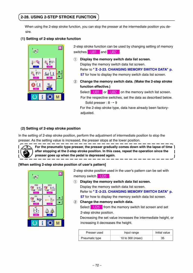
– 72 –
2-28. uSING 2-StEP StroKE FuNctIoN
2-step stroke funct�on can be used by chang�ng sett�ng of memory sw�tches and .
1 Display the memory switch data list screen. D�splay the memory sw�tch data l�st screen. Refer to "@-2-23. cHaNGING MEMorY SWItcH Data" p.
57 for how to d�splay the memory sw�tch data l�st screen.
2 change the memory switch data. (Make the 2-step stroke function effective.)
Select or on the memory sw�tch l�st screen. For the respect�ve sw�tches, set the data as descr�bed below.
Sol�d presser : 8 / 9 For the 2-step stroke type, data have already been factory-
adjusted.
When us�ng the 2-step stroke funct�on, you can stop the presser at the �ntermed�ate pos�t�on you de-s�re.
(1) Setting of 2-step stroke function
(2) Setting of 2-step stroke position
In the sett�ng of 2-step stroke pos�t�on, perform the adjustment of �ntermed�ate pos�t�on to stop the presser. As the sett�ng value �s �ncreased, the presser stops at the lower pos�t�on.
For the pneumatic type presser, the presser gradually comes down with the lapse of time after stopping at the 2-step stroke position. In this case, repeat the operation since the presser goes up when the pedal is depressed again.
[When setting 2-step stroke position of user's pattern]2-step stroke pos�t�on used �n the user's pattern can be set w�th memory sw�tch .1 Display the memory switch data list screen. D�splay the memory sw�tch data l�st screen. Refer to "@-2-23. cHaNGING MEMorY SWItcH Data" p.
57 for how to d�splay the memory sw�tch data l�st screen.2 change the memory switch data. Select from the memory sw�tch l�st screen and set
2-step stroke pos�t�on. Decreas�ng the set value �ncreases the �ntermed�ate he�ght, or
�ncreas�ng �t decreases the he�ght.
Presser used Input range In�t�al value
Pneumat�c type 10 to 300 (msec) 35
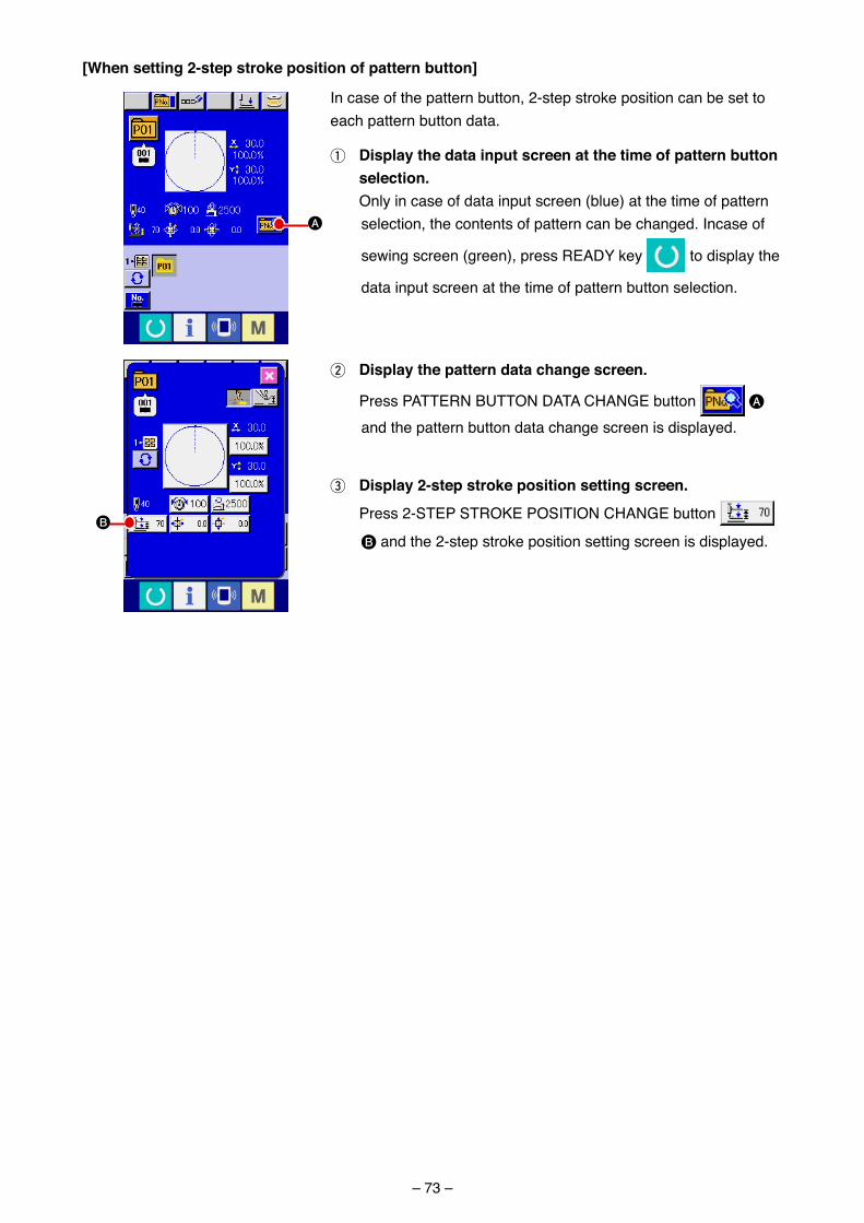
– 73 –
A
B
[When setting 2-step stroke position of pattern button]
In case of the pattern button, 2-step stroke pos�t�on can be set to each pattern button data.
1 Display the data input screen at the time of pattern button selection.
Only �n case of data �nput screen (blue) at the t�me of pattern select�on, the contents of pattern can be changed. Incase of
sew�ng screen (green), press READY key to d�splay the
data �nput screen at the t�me of pattern button select�on.
2 Display the pattern data change screen.
Press PATTERN BUTTON DATA CHANGE button A and the pattern button data change screen �s d�splayed.
3 Display 2-step stroke position setting screen.
Press 2-STEP STROKE POSITION CHANGE button
B and the 2-step stroke pos�t�on sett�ng screen �s d�splayed.
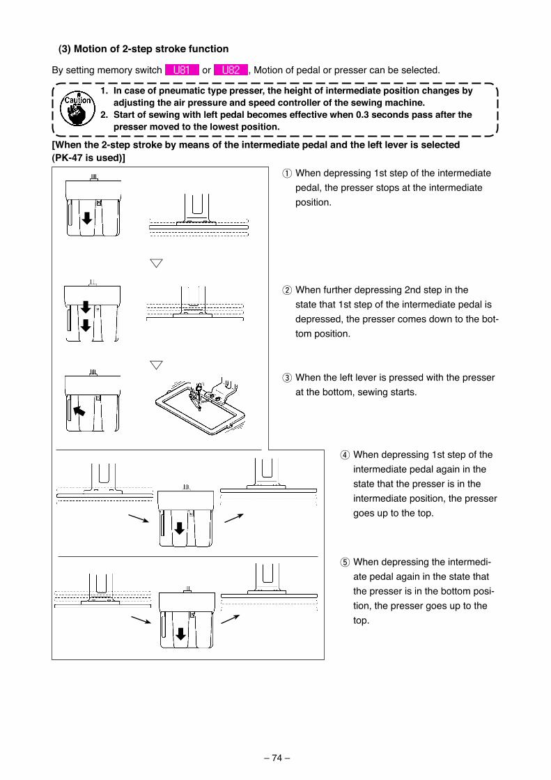
– 74 –
(3)Motionof2-stepstrokefunction
By setting memory switch or , Motion of pedal or presser can be selected.
1.Incaseofpneumatictypepresser,theheightofintermediatepositionchangesbyadjustingtheairpressureandspeedcontrollerofthesewingmachine.
2.Startofsewingwithleftpedalbecomeseffectivewhen0.3secondspassafterthepressermovedtothelowestposition.
1 When depressing 1st step of the intermediate pedal, the presser stops at the intermediate position.
2 When further depressing 2nd step in the state that 1st step of the intermediate pedal is depressed, the presser comes down to the bot-tom position.
3 When the left lever is pressed with the presser at the bottom, sewing starts.
4 When depressing 1st step of the intermediate pedal again in the state that the presser is in the intermediate position, the presser goes up to the top.
5 When depressing the intermedi-ate pedal again in the state that the presser is in the bottom posi-tion, the presser goes up to the top.
[Whenthe2-stepstrokebymeansoftheintermediatepedalandtheleftleverisselected(PK-47isused)]
uu
d
dd
d
d
d
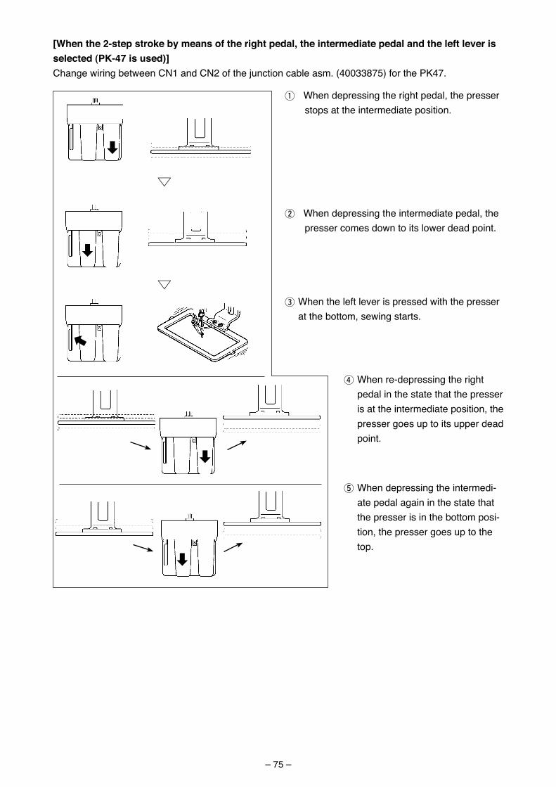
– 75 –
d
d
dd
d
uu
1 When depress�ng the r�ght pedal, the presser stops at the �ntermed�ate pos�t�on.
2 When depress�ng the �ntermed�ate pedal, the presser comes down to �ts lower dead po�nt.
3 When the left lever �s pressed w�th the presser at the bottom, sew�ng starts.
4 When re-depress�ng the r�ght pedal �n the state that the presser �s at the �ntermed�ate pos�t�on, the presser goes up to �ts upper dead po�nt.
5 When depress�ng the �ntermed�-ate pedal aga�n �n the state that the presser �s �n the bottom pos�-t�on, the presser goes up to the top.
[When the 2-step stroke by means of the right pedal, the intermediate pedal and the left lever is selected (PK-47 is used)]Change w�r�ng between CN1 and CN2 of the junct�on cable asm. (40033875) for the PK47.
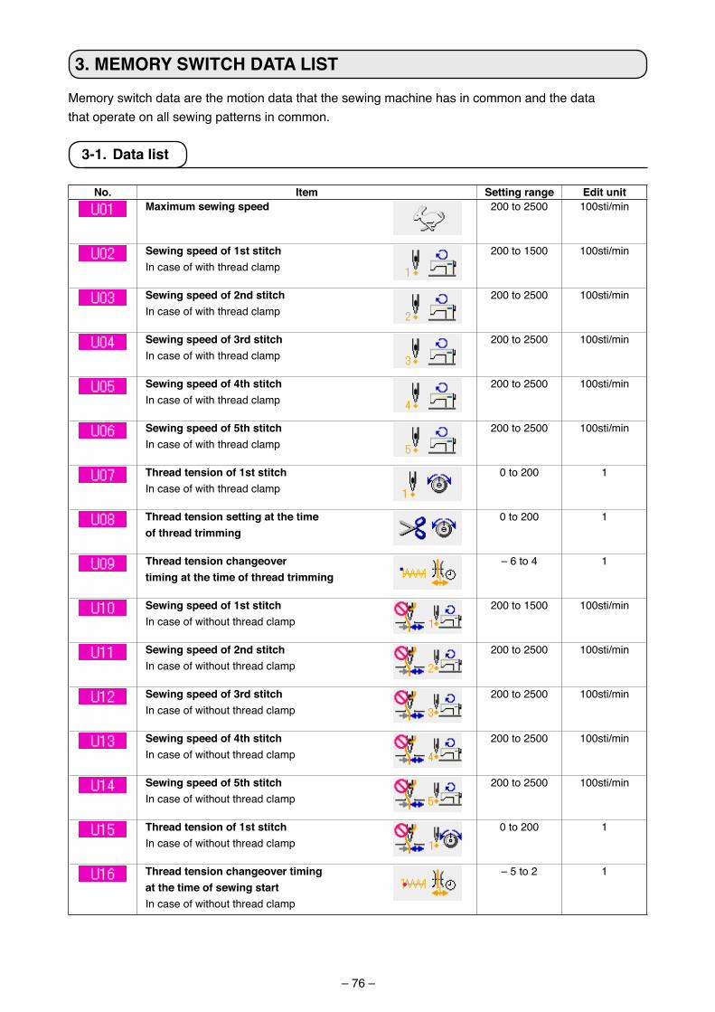
– 76 –
3. MEMorY SWItcH Data LISt
Memory sw�tch data are the mot�on data that the sew�ng mach�ne has �n common and the datathat operate on all sew�ng patterns �n common.
3-1. Data list
No. Item Setting range Edit unitMaximum sewing speed 200 to 2500 100st�/m�n
Sewing speed of 1st stitchIn case of w�th thread clamp
200 to 1500 100st�/m�n
Sewing speed of 2nd stitchIn case of w�th thread clamp
200 to 2500 100st�/m�n
Sewing speed of 3rd stitchIn case of w�th thread clamp
200 to 2500 100st�/m�n
Sewing speed of 4th stitchIn case of w�th thread clamp
200 to 2500 100st�/m�n
Sewing speed of 5th stitchIn case of w�th thread clamp
200 to 2500 100st�/m�n
thread tension of 1st stitchIn case of w�th thread clamp
0 to 200 1
thread tension setting at the time of thread trimming
0 to 200 1
thread tension changeovertiming at the time of thread trimming
– 6 to 4 1
Sewing speed of 1st stitch In case of w�thout thread clamp
200 to 1500 100st�/m�n
Sewing speed of 2nd stitchIn case of w�thout thread clamp
200 to 2500 100st�/m�n
Sewing speed of 3rd stitchIn case of w�thout thread clamp
200 to 2500 100st�/m�n
Sewing speed of 4th stitchIn case of w�thout thread clamp
200 to 2500 100st�/m�n
Sewing speed of 5th stitchIn case of w�thout thread clamp
200 to 2500 100st�/m�n
thread tension of 1st stitchIn case of w�thout thread clamp
0 to 200 1
thread tension changeover timing at the time of sewing startIn case of w�thout thread clamp
– 5 to 2 1
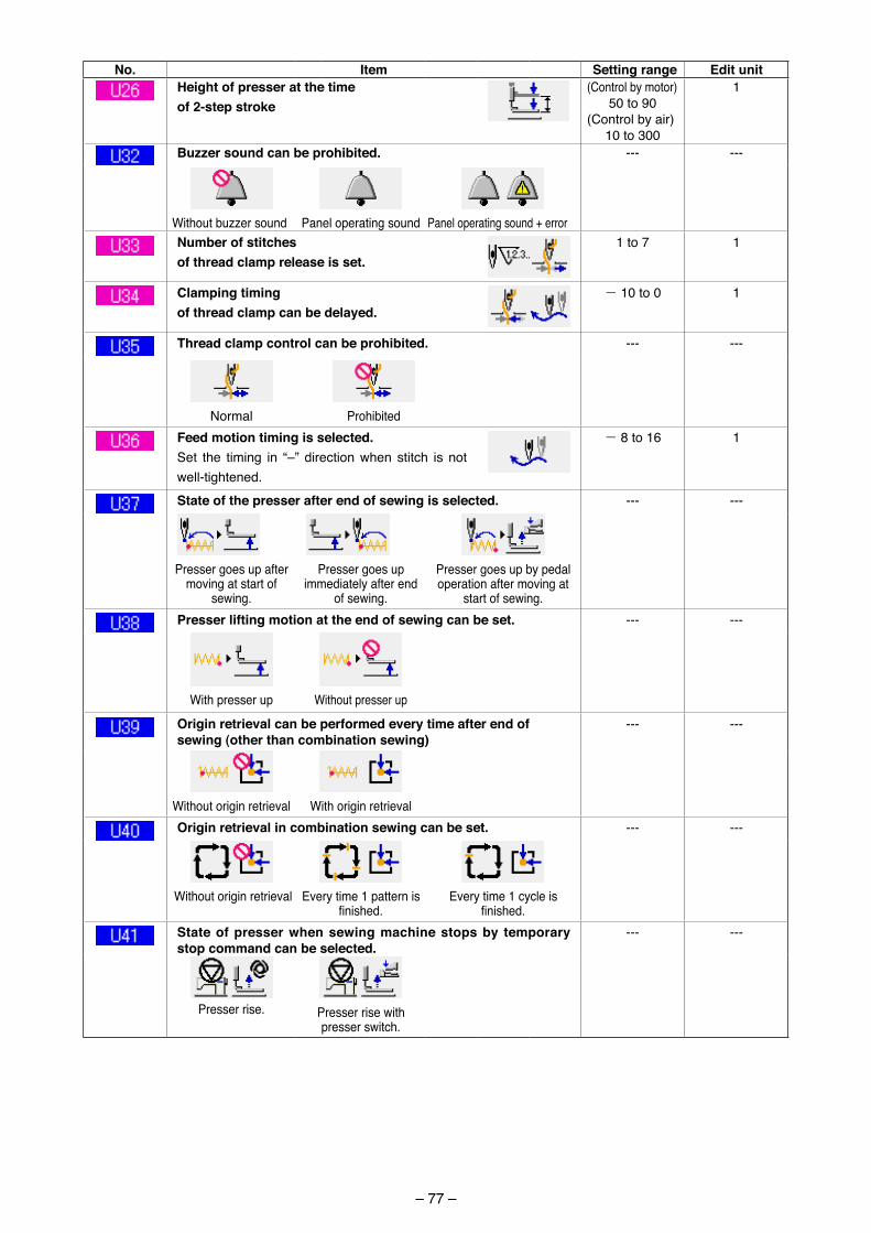
– 77 –
No. Item Setting range Edit unitHeight of presser at the time of 2-step stroke
(Control by motor)50 to 90
(Control by a�r)10 to 300
1
Buzzer sound can be prohibited. --- ---
W�thout buzzer sound Panel operat�ng sound Panel operat�ng sound + errorNumber of stitches of thread clamp release is set.
1 to 7 1
clamping timing of thread clamp can be delayed.
- 10 to 0 1
thread clamp control can be prohibited. --- ---
Normal Proh�b�tedFeed motion timing is selected.Set the t�m�ng �n “–” d�rect�on when st�tch �s not well-t�ghtened.
- 8 to 16 1
State of the presser after end of sewing is selected. --- ---
Presser goes up after mov�ng at start of
sew�ng.
Presser goes up �mmed�ately after end
of sew�ng.
Presser goes up by pedal operat�on after mov�ng at
start of sew�ng.Presser lifting motion at the end of sewing can be set. --- ---
W�th presser up W�thout presser up
origin retrieval can be performed every time after end of sewing (other than combination sewing)
--- ---
W�thout or�g�n retr�eval W�th or�g�n retr�evalorigin retrieval in combination sewing can be set. --- ---
W�thout or�g�n retr�eval Every t�me 1 pattern �s finished.
Every t�me 1 cycle �s finished.
State of presser when sewing machine stops by temporary stop command can be selected.
--- ---
Presser r�se. Presser r�se w�th presser sw�tch.
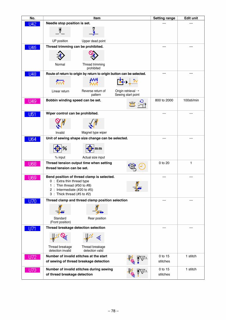
– 78 –
No. Item Setting range Edit unitNeedle stop position is set. --- ---
UP pos�t�on Upper dead po�ntthread trimming can be prohibited. --- ---
Normal Thread tr�mm�ng proh�b�ted
route of return to origin by return to origin button can be selected. --- ---
L�near return Reverse return of pattern
Or�g�n retr�eval / Sew�ng start po�nt
Bobbin winding speed can be set. 800 to 2000 100st�/m�n
Wiper control can be prohibited. --- ---
Inval�d Magnet type w�perunit of sewing shape size change can be selected. --- ---
% �nput Actual s�ze �nputthread tension output time when setting thread tension can be set.
0 to 20 1
Bend position of thread clamp is selected.0 : Extra th�n thread type1 : Th�n thread (#50 to #8)2 : Intermed�ate (#20 to #5)3 : Th�ck thread (#5 to #2)
--- ---
thread clamp and thread clamp position selection --- ---
Standard (Front pos�t�on)
Rear pos�t�on
thread breakage detection selection --- ---
Thread breakage detect�on �nval�d
Thread breakage detect�on val�d
Number of invalid stitches at the start of sewing of thread breakage detection
0 to 15 st�tches
1 st�tch
Number of invalid stitches during sewing of thread breakage detection
0 to 15 st�tches
1 st�tch
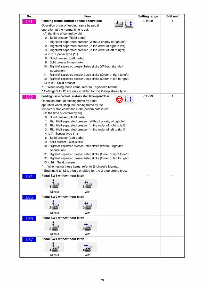
– 79 –
No. Item Setting range Edit unitFeeding frame control : pedal open/closeOperat�on order of feed�ng frame by pedal operat�on at the normal t�me �s set.
0 to 99 1
(At the t�me of control by a�r) 0 : Sol�d presser (R�ght pedal) 1 : R�ght/left separated presser (W�thout pr�or�ty of r�ght/left) 2 : R�ght/left separated presser (In the order of r�ght to left) 3 : R�ght/left separated presser (In the order of left to r�ght) 4 to 7 : Spec�al type (*1) 8 : Sol�d presser (Left pedal) 9 : Sol�d presser 2-step stroke10 : R�ght/left separated presser 2-step stroke (W�thout r�ght/left
separat�on)11 : R�ght/left separated presser 2-step stroke (Order of r�ght to left)12 : R�ght/left separated presser 2-step stroke (Order of left to r�ght)13 to 99 : Sol�d presser
*1 : When us�ng these �tems, refer to Eng�neer's Manual.* Sett�ngs 9 to 12 are only enabled for the 2-step stroke type.Feeding frame control : midway stop time open/closeOperat�on order of feed�ng frame by pedal operat�on when l�ft�ng the feed�ng frame by the temporary stop command �n the pattern data �s set.
0 to 99 1
(At the t�me of control by a�r) 0 : Sol�d presser (R�ght pedal) 1 : R�ght/left separated presser (W�thout pr�or�ty of r�ght/left) 2 : R�ght/left separated presser (In the order of r�ght to left) 3 : R�ght/left separated presser (In the order of left to r�ght) 4 to 7 : Spec�al type (*1) 8 : Sol�d presser (Left pedal) 9 : Sol�d presser 2-step stroke10 : R�ght/left separated presser 2-step stroke (W�thout r�ght/left
separat�on)11 : R�ght/left separated presser 2-step stroke (Order of r�ght to left)12 : R�ght/left separated presser 2-step stroke (Order of left to r�ght)13 to 99 : Sol�d presser
*1 : When us�ng these �tems, refer to Eng�neer's Manual.* Sett�ngs 9 to 12 are only enabled for the 2-step stroke type.Pedal SW1 with/without latch --- ---
W�thout W�thPedal SW2 with/without latch --- ---
W�thout W�thPedal SW3 with/without latch --- ---
W�thout W�thPedal SW4 with/without latch --- ---
W�thout W�th
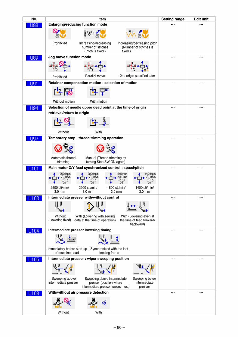
– 80 –
No. Item Setting range Edit unitEnlarging/reducing function mode --- ---
Proh�b�ted Increas�ng/decreas�ng number of st�tches
(Pitch is fixed.)
Increas�ng/decreas�ng p�tch (Number of st�tches �s fixed.)
Jog move function mode --- ---
Proh�b�ted Parallel move 2nd origin specified later
retainer compensation motion : selection of motion --- ---
W�thout mot�on W�th mot�onSelection of needle upper dead point at the time of origin retrieval/return to origin
--- ---
W�thout W�thtemporary stop : thread trimming operation --- ---
Automat�c thread tr�mm�ng
Manual (Thread tr�mm�ng by turn�ng Stop SW ON aga�n)
Main motor X/Y feed synchronized control : speed/pitch --- ---
2500 st�/m�n/ 3.0 mm
2200 st�/m�n/ 3.0 mm
1800 st�/m�n/ 3.0 mm
1400 st�/m�n/ 3.0 mm
Intermediate presser with/without control --- ---
W�thout (Lowering fixed)
W�th (Lower�ng w�th sew�ng data at the t�me of operat�on)
W�th (Lower�ng even at the t�me of feed forward/
backward)Intermediate presser lowering timing --- ---
Immed�ately before start-up of mach�ne head
Synchron�zed w�th the last feed�ng frame
Intermediate presser : wiper sweeping position --- ---
Sweep�ng above �ntermed�ate presser
Sweep�ng above �ntermed�ate presser (pos�t�on where
�ntermed�ate presser lowers most)
Sweep�ng below �ntermed�ate
presserWith/without air pressure detection --- ---
W�thout W�th
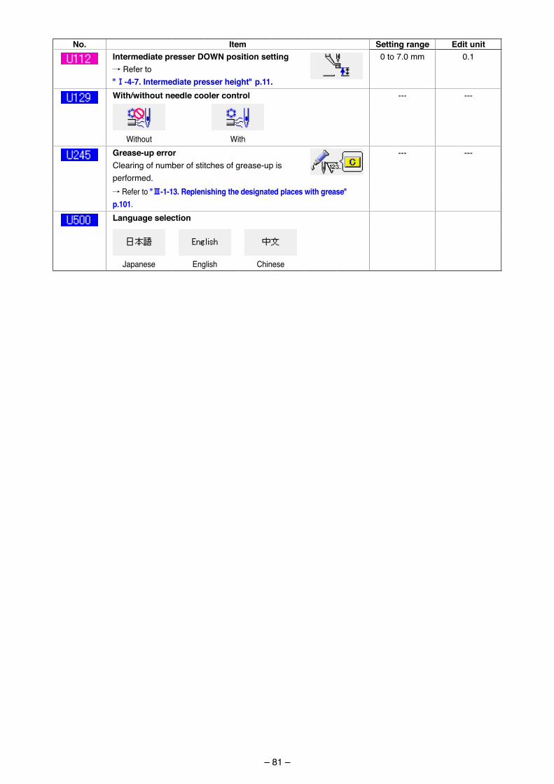
– 81 –
No. Item Setting range Edit unitIntermediate presser DoWN position setting/ Refer to "!-4-7. Intermediate presser height" p.11.
0 to 7.0 mm 0.1
With/without needle cooler control --- ---
W�thout W�thGrease-up errorClear�ng of number of st�tches of grease-up �s performed.
--- ---
/ Refer to "#-1-13. replenishing the designated places with grease" p.101.Language selection
Japanese Engl�sh Ch�nese
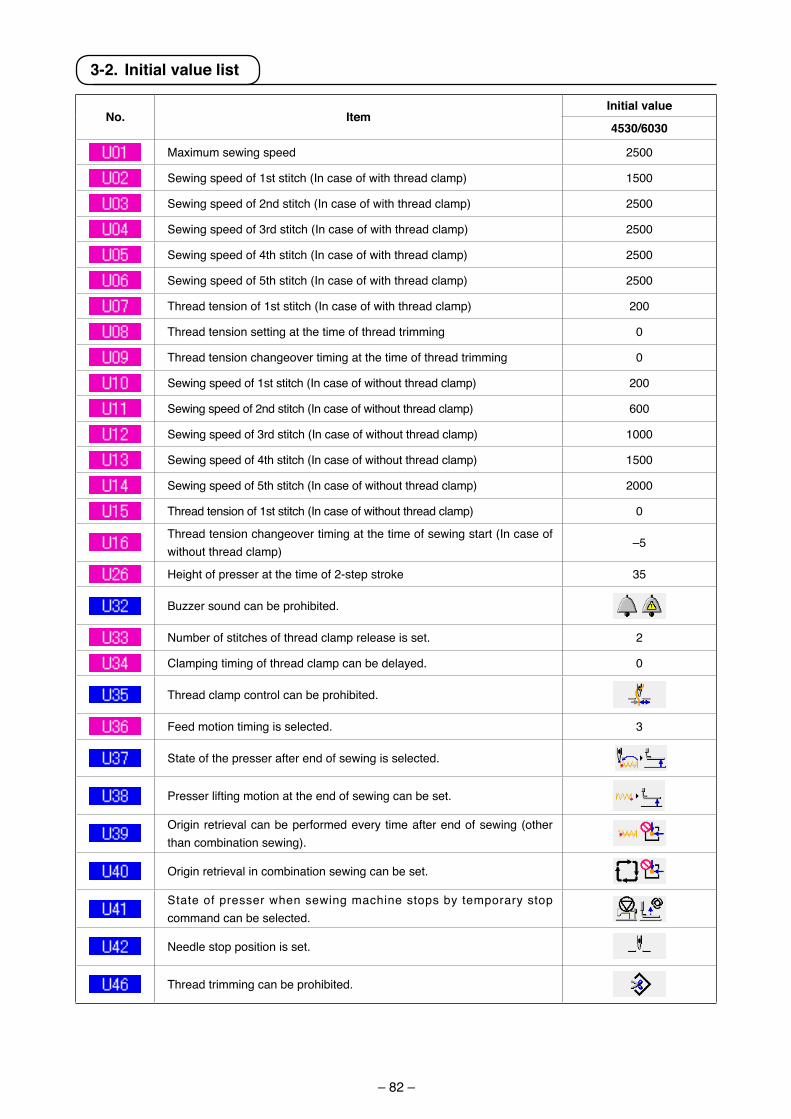
– 82 –
3-2. Initial value list
No. ItemInitial value
4530/6030
Max�mum sew�ng speed 2500
Sew�ng speed of 1st st�tch (In case of w�th thread clamp) 1500
Sew�ng speed of 2nd st�tch (In case of w�th thread clamp) 2500
Sew�ng speed of 3rd st�tch (In case of w�th thread clamp) 2500
Sew�ng speed of 4th st�tch (In case of w�th thread clamp) 2500
Sew�ng speed of 5th st�tch (In case of w�th thread clamp) 2500
Thread tens�on of 1st st�tch (In case of w�th thread clamp) 200
Thread tens�on sett�ng at the t�me of thread tr�mm�ng 0
Thread tens�on changeover t�m�ng at the t�me of thread tr�mm�ng 0
Sew�ng speed of 1st st�tch (In case of w�thout thread clamp) 200
Sew�ng speed of 2nd st�tch (In case of w�thout thread clamp) 600
Sew�ng speed of 3rd st�tch (In case of w�thout thread clamp) 1000
Sew�ng speed of 4th st�tch (In case of w�thout thread clamp) 1500
Sew�ng speed of 5th st�tch (In case of w�thout thread clamp) 2000
Thread tens�on of 1st st�tch (In case of w�thout thread clamp) 0
Thread tens�on changeover t�m�ng at the t�me of sew�ng start (In case of w�thout thread clamp)
–5
He�ght of presser at the t�me of 2-step stroke 35
Buzzer sound can be proh�b�ted.
Number of st�tches of thread clamp release �s set. 2
Clamp�ng t�m�ng of thread clamp can be delayed. 0
Thread clamp control can be proh�b�ted.
Feed mot�on t�m�ng �s selected. 3
State of the presser after end of sew�ng �s selected.
Presser l�ft�ng mot�on at the end of sew�ng can be set.
Or�g�n retr�eval can be performed every t�me after end of sew�ng (other than comb�nat�on sew�ng).
Or�g�n retr�eval �n comb�nat�on sew�ng can be set.
State of presser when sew�ng mach�ne stops by temporary stop command can be selected.
Needle stop pos�t�on �s set.
Thread tr�mm�ng can be proh�b�ted.
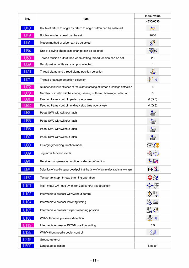
– 83 –
No. ItemInitial value
4530/6030
Route of return to or�g�n by return to or�g�n button can be selected.
Bobb�n w�nd�ng speed can be set. 1600
Mot�on method of w�per can be selected.
Un�t of sew�ng shape s�ze change can be selected.
Thread tens�on output t�me when sett�ng thread tens�on can be set. 20
Bend pos�t�on of thread clamp �s selected. 1
Thread clamp and thread clamp pos�t�on select�on
Thread breakage detect�on select�on
Number of �nval�d st�tches at the start of sew�ng of thread breakage detect�on 8
Number of �nval�d st�tches dur�ng sew�ng of thread breakage detect�on 3
Feed�ng frame control : pedal open/close 0 (G:8)
Feed�ng frame control : m�dway stop t�me open/close 0 (G:8)
Pedal SW1 w�th/w�thout latch
Pedal SW2 w�th/w�thout latch
Pedal SW3 w�th/w�thout latch
Pedal SW4 w�th/w�thout latch
Enlarg�ng/reduc�ng funct�on mode
Jog move funct�on mode
Reta�ner compensat�on mot�on : select�on of mot�on
Select�on of needle upper dead po�nt at the t�me of or�g�n retr�eval/return to or�g�n
Temporary stop : thread tr�mm�ng operat�on
Ma�n motor X/Y feed synchron�zed control : speed/p�tch
Intermed�ate presser w�th/w�thout control
Intermed�ate presser lower�ng t�m�ng
Intermed�ate presser : w�per sweep�ng pos�t�on
W�th/w�thout a�r pressure detect�on
Intermed�ate presser DOWN pos�t�on sett�ng 3.5
W�th/w�thout needle cooler control
Grease-up error -
Language select�on Not set
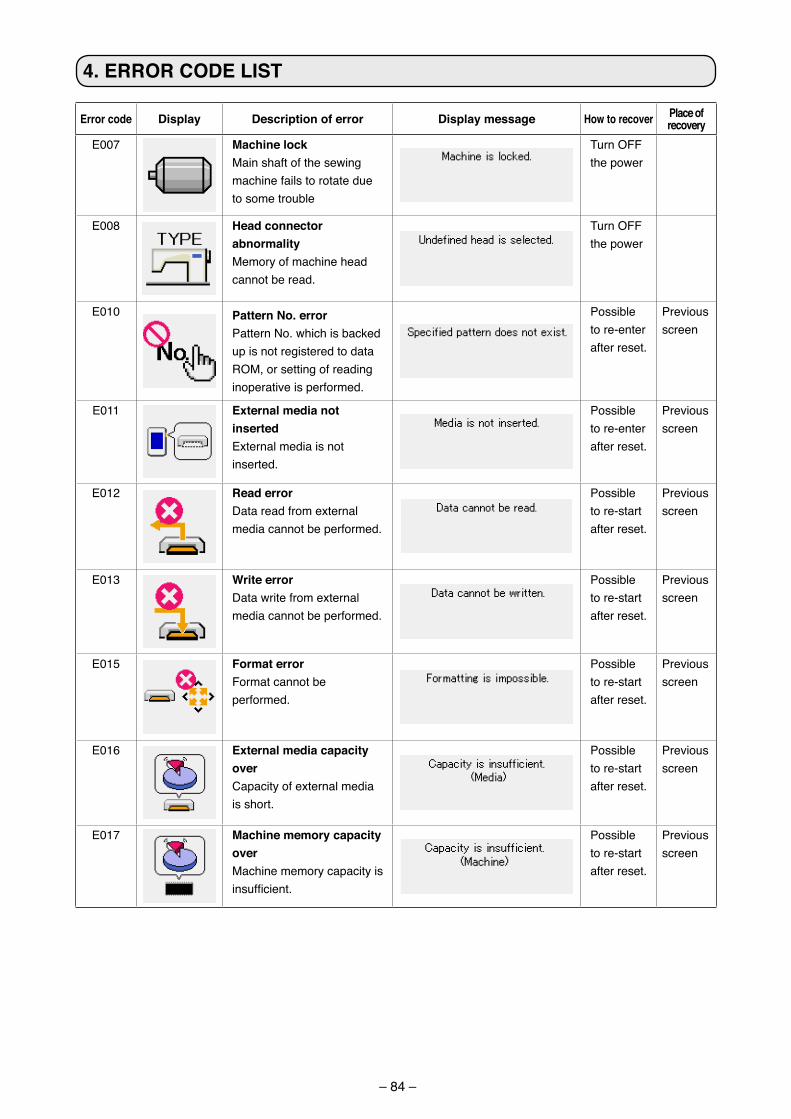
– 84 –
4. Error coDE LISt
Error code Display Description of error Display message How to recover Place of recovery
E007 Machine lockMa�n shaft of the sew�ng mach�ne fa�ls to rotate due to some trouble
Turn OFF the power
E008 Head connector abnormalityMemory of mach�ne head cannot be read.
Turn OFF the power
E010 Pattern No. errorPattern No. wh�ch �s backed up �s not reg�stered to data ROM, or sett�ng of read�ng �noperat�ve �s performed.
Poss�ble to re-enter after reset.
Prev�ous screen
E011 External media not insertedExternal med�a �s not �nserted.
Poss�ble to re-enter after reset.
Prev�ous screen
E012 read errorData read from external med�a cannot be performed.
Poss�ble to re-start after reset.
Prev�ous screen
E013 Write errorData wr�te from external med�a cannot be performed.
Poss�ble to re-start after reset.
Prev�ous screen
E015 Format errorFormat cannot be performed.
Poss�ble to re-start after reset.
Prev�ous screen
E016 External media capacity overCapac�ty of external med�a �s short.
Poss�ble to re-start after reset.
Prev�ous screen
E017 Machine memory capacity overMach�ne memory capac�ty �s insufficient.
Poss�ble to re-start after reset.
Prev�ous screen
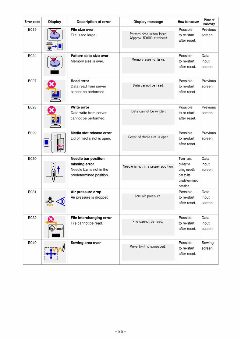
– 85 –
Error code Display Description of error Display message How to recover Place of recovery
E019 File size overF�le �s too large.
Poss�ble to re-start after reset.
Prev�ous screen
E024 Pattern data size overMemory s�ze �s over.
Poss�ble to re-start after reset.
Data �nputscreen
E027 read errorData read from server cannot be performed.
Poss�ble to re-start after reset.
Prev�ous screen
E028 Write errorData wr�te from server cannot be performed.
Poss�ble to re-start after reset.
Prev�ous screen
E029 Media slot release errorL�d of med�a slot �s open.
Poss�ble to re-start after reset.
Prev�ous screen
E030 Needle bar position missing errorNeedle bar �s not �n the predeterm�ned pos�t�on.
Turn hand pulley to br�ng needle bar to �ts predeterm�ned pos�t�on.
Data �nputscreen
E031 air pressure dropA�r pressure �s dropped.
Poss�ble to re-start after reset.
Data �nputscreen
E032 File interchanging errorF�le cannot be read.
Poss�ble to re-start after reset.
Data �nputscreen
E040 Sewing area over Poss�ble to re-start after reset.
Sew�ng screen
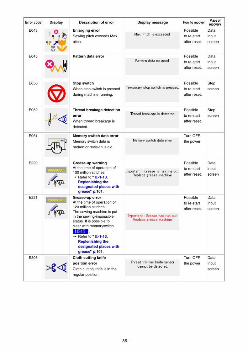
– 86 –
Error code Display Description of error Display message How to recover Place of recovery
E043 Enlarging errorSew�ng p�tch exceeds Max. p�tch.
Poss�ble to re-start after reset.
Data �nputscreen
E045 Pattern data error Poss�ble to re-start after reset.
Data �nputscreen
E050 Stop switchWhen stop sw�tch �s pressed dur�ng mach�ne runn�ng.
Poss�ble to re-start after reset.
Step screen
E052 thread breakage detection errorWhen thread breakage �s detected.
Poss�ble to re-start after reset.
Step screen
E061 Memory switch data errorMemory sw�tch data �s broken or rev�s�on �s old.
Turn OFF the power
E220 Grease-up warningAt the t�me of operat�on of 100 m�ll�on st�tches→ Refer to "#-1-13.
replenishing the designated places with grease" p.101.
Poss�ble to re-start after reset.
Data �nputscreen
E221 Grease-up errorAt the t�me of operat�on of 120 m�ll�on st�tchesThe sew�ng mach�ne �s put �n the sew�ng-�mposs�ble status. It �s poss�ble to clear w�th memorysw�tch
.→ Refer to "#-1-13.
replenishing the designated places with grease" p.101.
Poss�ble to re-start after reset.
Data �nputscreen
E305 cloth cutting knife position errorCloth cutt�ng kn�fe �s �n the regular pos�t�on.
Turn OFF the power
Data �nputscreen
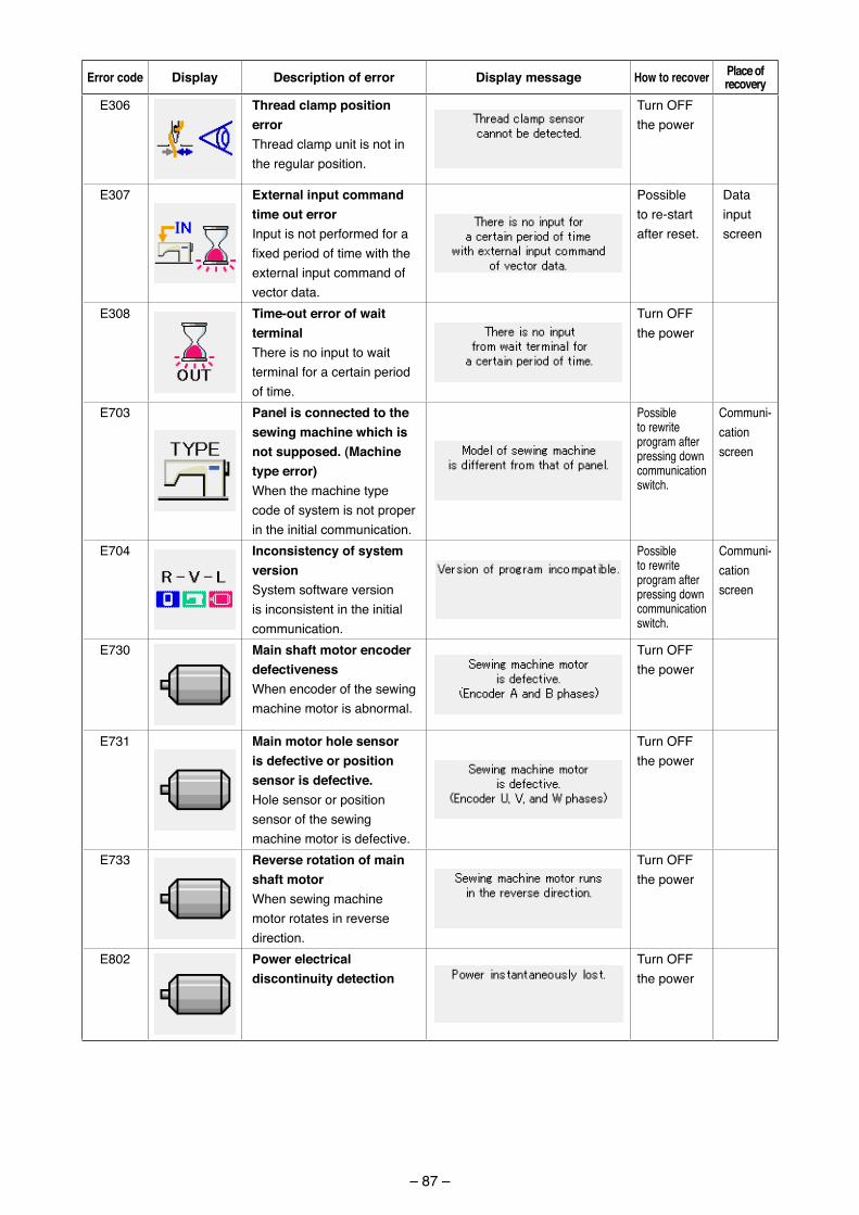
– 87 –
Error code Display Description of error Display message How to recover Place of recovery
E306 thread clamp position errorThread clamp un�t �s not �n the regular pos�t�on.
Turn OFF the power
E307 External input command time out errorInput �s not performed for a fixed period of time with the external �nput command of vector data.
Poss�ble to re-start after reset.
Data �nputscreen
E308 time-out error of wait terminalThere �s no �nput to wa�t term�nal for a certa�n per�od of t�me.
Turn OFF the power
E703 Panel is connected to the sewing machine which is not supposed. (Machine type error)When the mach�ne type code of system �s not proper �n the �n�t�al commun�cat�on.
Poss�ble to rewr�te program after press�ng down commun�cat�on sw�tch.
Commun�-cat�onscreen
E704 Inconsistency of system versionSystem software vers�on �s �ncons�stent �n the �n�t�al commun�cat�on.
Poss�ble to rewr�te program after press�ng down commun�cat�on sw�tch.
Commun�-cat�onscreen
E730 Main shaft motor encoder defectivenessWhen encoder of the sew�ng mach�ne motor �s abnormal.
Turn OFF the power
E731 Main motor hole sensor is defective or position sensor is defective.Hole sensor or pos�t�on sensor of the sew�ng mach�ne motor �s defect�ve.
Turn OFF the power
E733 reverse rotation of main shaft motorWhen sew�ng mach�ne motor rotates �n reverse d�rect�on.
Turn OFF the power
E802 Power electrical discontinuity detection
Turn OFF the power
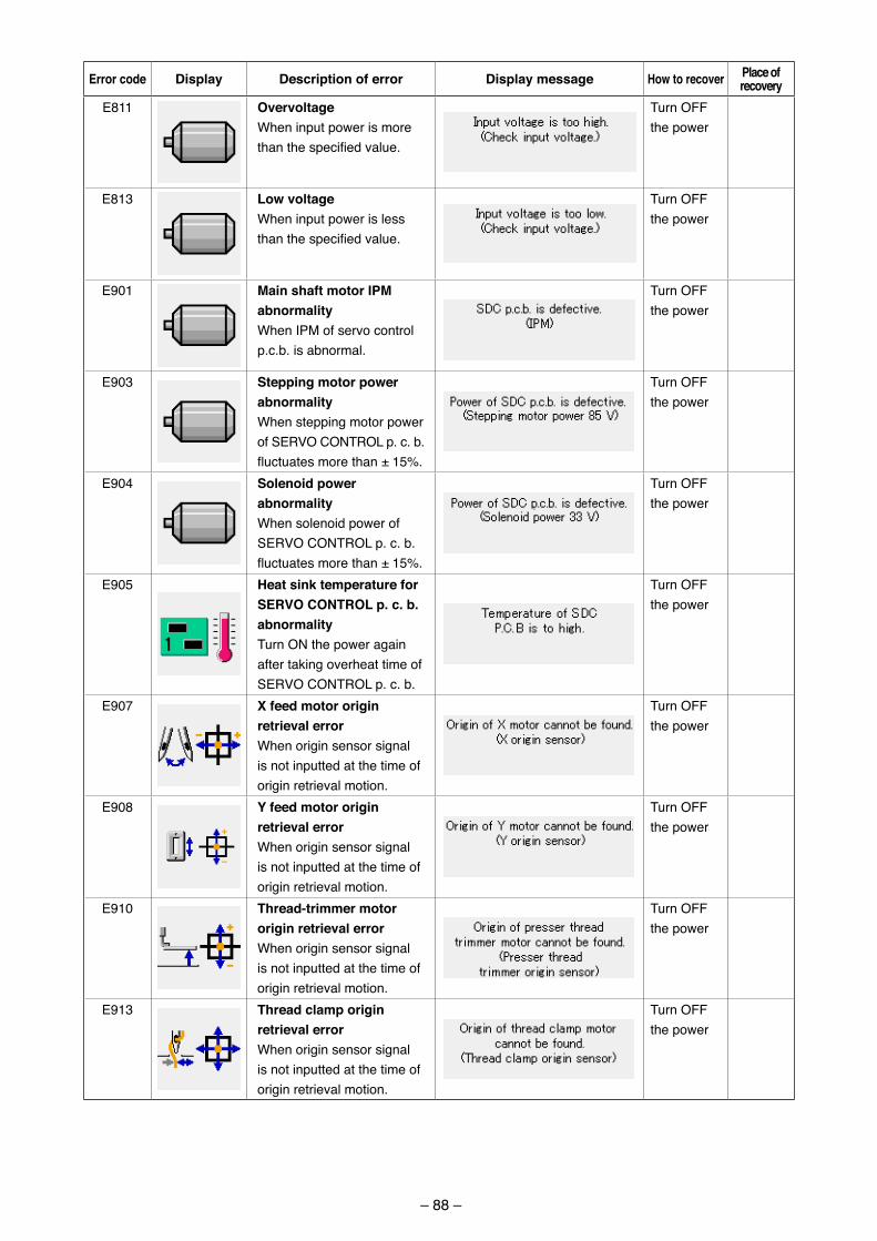
– 88 –
Error code Display Description of error Display message How to recover Place of recovery
E811 overvoltageWhen �nput power �s more than the specified value.
Turn OFF the power
E813 Low voltageWhen �nput power �s less than the specified value.
Turn OFF the power
E901 Main shaft motor IPM abnormalityWhen IPM of servo control p.c.b. �s abnormal.
Turn OFF the power
E903 Stepping motor power abnormalityWhen stepp�ng motor power of SERVO CONTROL p. c. b. fluctuates more than ± 15%.
Turn OFF the power
E904 Solenoid power abnormalityWhen soleno�d power of SERVO CONTROL p. c. b.fluctuates more than ± 15%.
Turn OFF the power
E905 Heat sink temperature for SErVo coNtroL p. c. b. abnormalityTurn ON the power aga�n after tak�ng overheat t�me of SERVO CONTROL p. c. b.
Turn OFF the power
E907 X feed motor origin retrieval errorWhen or�g�n sensor s�gnal �s not �nputted at the t�me of or�g�n retr�eval mot�on.
Turn OFF the power
E908 Y feed motor origin retrieval errorWhen or�g�n sensor s�gnal �s not �nputted at the t�me of or�g�n retr�eval mot�on.
Turn OFF the power
E910 thread-trimmer motor origin retrieval errorWhen or�g�n sensor s�gnal �s not �nputted at the t�me of or�g�n retr�eval mot�on.
Turn OFF the power
E913 thread clamp origin retrieval errorWhen or�g�n sensor s�gnal �s not �nputted at the t�me of or�g�n retr�eval mot�on.
Turn OFF the power
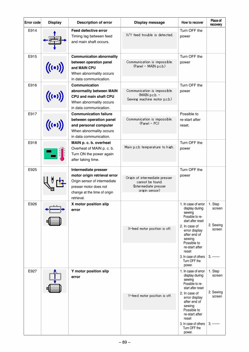
– 89 –
Error code Display Description of error Display message How to recover Place of recovery
E914 Feed defective errorT�m�ng lag between feed and ma�n shaft occurs.
Turn OFF the power
E915 communication abnormality between operation panel and MaIN cPuWhen abnormal�ty occurs �n data commun�cat�on.
Turn OFF the power
E916 communication abnormality between MaIN cPu and main shaft cPuWhen abnormal�ty occurs �n data commun�cat�on.
Turn OFF the power
E917 communication failure between operation panel and personal computerWhen abnormal�ty occurs �n data commun�cat�on.
Poss�ble to re-start after reset.
E918 MaIN p. c. b. overheat Overheat of MAIN p. c. b.Turn ON the power aga�n after tak�ng t�me.
Turn OFF the power
E925 Intermediate presser motor origin retrieval errorOr�g�n sensor of �ntermed�ate presser motor does not change at the t�me of or�g�n retr�eval.
Turn OFF the power
E926 X motor position slip error
1. In case of error d�splay dur�ng sew�ng
Poss�ble to re-start after reset
2. In case of error d�splay after end of sew�ng
Poss�ble to re-start after reset
3. In case of others Turn OFF the
power.
1. Step screen
2. Sew�ng screen
3. -------
E927 Y motor position slip error
1. In case of error d�splay dur�ng sew�ng
Poss�ble to re-start after reset
2. In case of error d�splay after end of sew�ng
Poss�ble to re-start after reset
3. In case of others Turn OFF the
power.
1. Step screen
2. Sew�ng screen
3. -------
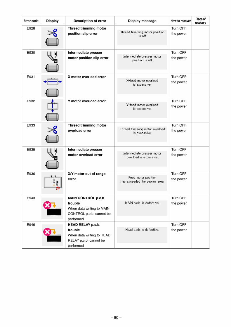
– 90 –
Error code Display Description of error Display message How to recover Place of recovery
E928 thread trimming motor position slip error
Turn OFF the power
E930 Intermediate presser motor position slip error
Turn OFF the power
E931 X motor overload error Turn OFF the power
E932 Y motor overload error Turn OFF the power
E933 thread trimming motor overload error
Turn OFF the power
E935 Intermediate presser motor overload error
Turn OFF the power
E936 X/Y motor out of range error
Turn OFF the power
E943 MaIN coNtroL p.c.b troubleWhen data wr�t�ng to MAIN CONTROL p.c.b. cannot be performed
Turn OFF the power
E946 HEaD rELaY p.c.b. troubleWhen data wr�t�ng to HEAD RELAY p.c.b. cannot be performed
Turn OFF the power
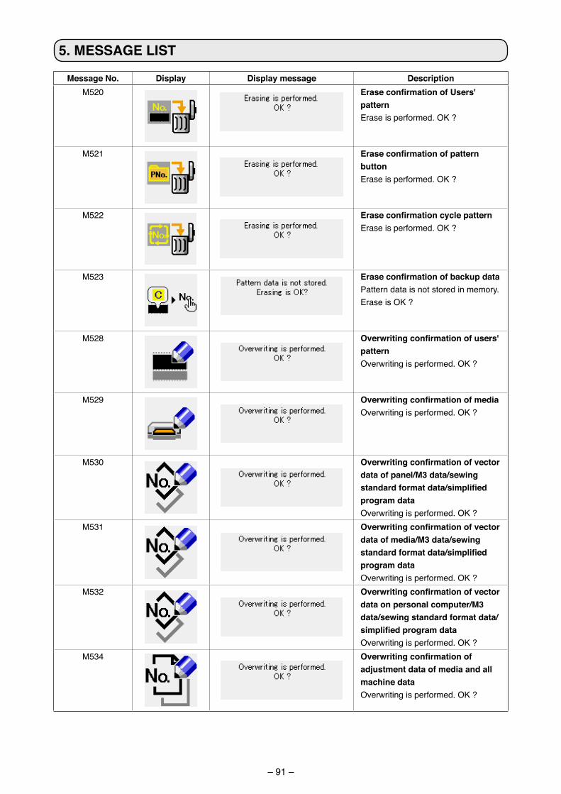
– 91 –
Message No. Display Display message DescriptionM520 EraseconfirmationofUsers'
pattern Erase �s performed. OK ?
M521 Eraseconfirmationofpatternbutton Erase �s performed. OK ?
M522 EraseconfirmationcyclepatternErase �s performed. OK ?
M523 EraseconfirmationofbackupdataPattern data �s not stored �n memory. Erase �s OK ?
M528 Overwritingconfirmationofusers'pattern Overwr�t�ng �s performed. OK ?
M529 OverwritingconfirmationofmediaOverwr�t�ng �s performed. OK ?
M530 Overwritingconfirmationofvectordata of panel/M3 data/sewing standardformatdata/simplifiedprogram data Overwr�t�ng �s performed. OK ?
M531 Overwritingconfirmationofvectordata of media/M3 data/sewing standardformatdata/simplifiedprogram dataOverwr�t�ng �s performed. OK ?
M532 Overwritingconfirmationofvectordata on personal computer/M3 data/sewing standard format data/simplifiedprogramdataOverwr�t�ng �s performed. OK ?
M534 Overwritingconfirmationofadjustment data of media and all machine dataOverwr�t�ng �s performed. OK ?
5. MESSaGE LISt
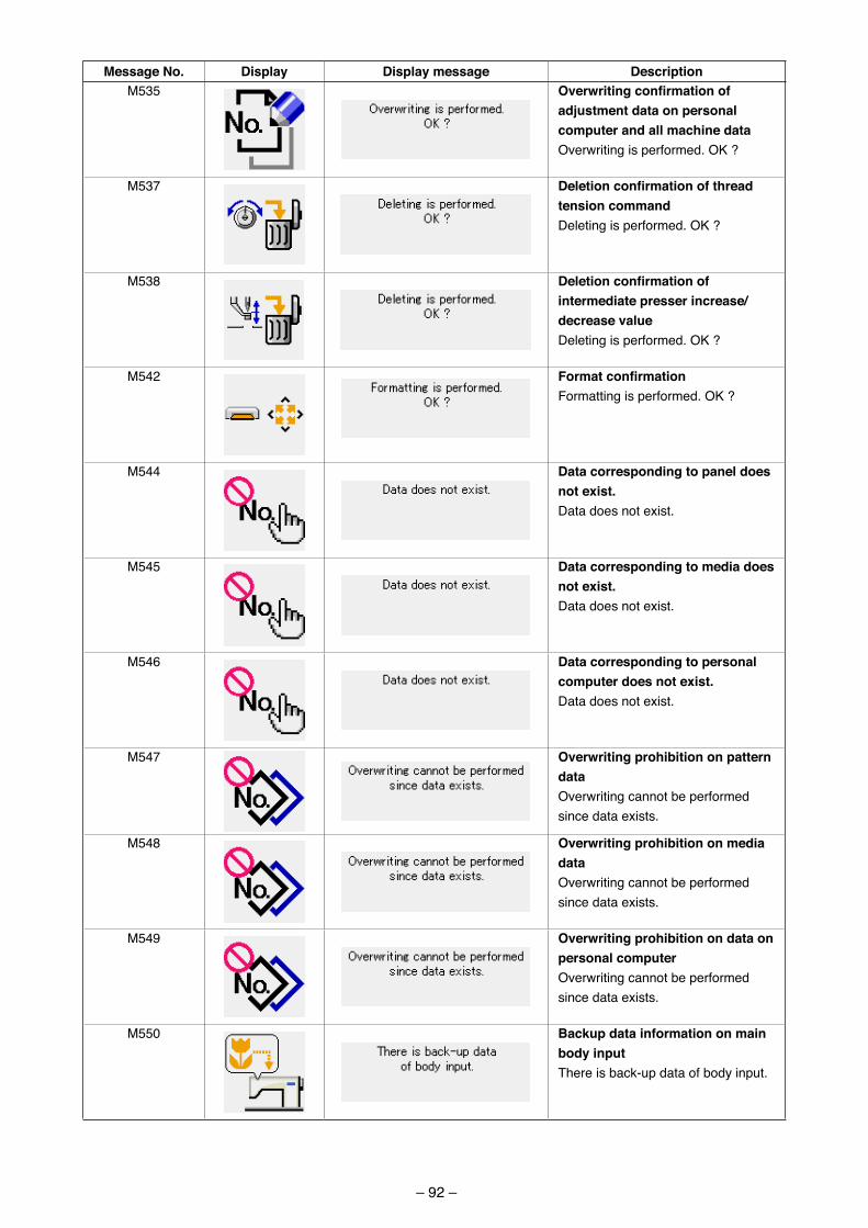
– 92 –
Message No. Display Display message DescriptionM535 Overwritingconfirmationof
adjustment data on personal computer and all machine data Overwr�t�ng �s performed. OK ?
M537 Deletionconfirmationofthreadtension commandDelet�ng �s performed. OK ?
M538 Deletionconfirmationofintermediate presser increase/decrease valueDelet�ng �s performed. OK ?
M542 FormatconfirmationFormatt�ng �s performed. OK ?
M544 Data corresponding to panel does not exist. Data does not ex�st.
M545 Data corresponding to media does not exist.Data does not ex�st.
M546 Data corresponding to personal computer does not exist.Data does not ex�st.
M547 overwriting prohibition on pattern dataOverwr�t�ng cannot be performed s�nce data ex�sts.
M548 overwriting prohibition on media data Overwr�t�ng cannot be performed s�nce data ex�sts.
M549 overwriting prohibition on data on personal computerOverwr�t�ng cannot be performed s�nce data ex�sts.
M550 Backup data information on main body input There �s back-up data of body �nput.

– 93 –
Message No. Display Display message DescriptionM653 During formatting
Formatt�ng �s performed.
M669 During data readingData �s be�ng read.
M670 During data writingData �s be�ng wr�tten.
M671 During data convertingData �s be�ng converted.
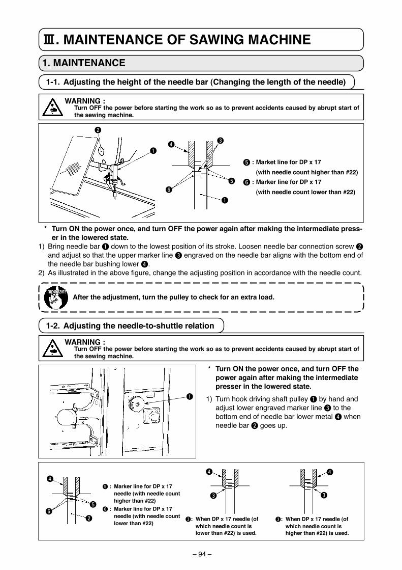
– 94 –
1-1. adjusting the height of the needle bar (changing the length of the needle)
* turn oN the power once, and turn oFF the power again after making the intermediate press-er in the lowered state.
1) Br�ng needle bar 1 down to the lowest pos�t�on of �ts stroke. Loosen needle bar connect�on screw 2 and adjust so that the upper marker l�ne 3 engraved on the needle bar al�gns w�th the bottom end of the needle bar bush�ng lower 4.
2) As illustrated in the above figure, change the adjusting position in accordance with the needle count.
after the adjustment, turn the pulley to check for an extra load.
1. MaINtENaNcE
5 : Market line for DP x 17 (with needle count higher than #22)6 : Marker line for DP x 17 (with needle count lower than #22)
1-2. adjusting the needle-to-shuttle relation
5 : Marker line for DP x 17 needle (with needle count higher than #22)
6 : Marker line for DP x 17 needle (with needle count lower than #22)
3: When DP x 17 needle (of which needle count is lower than #22) is used.
3: When DP x 17 needle (of which needle count is higher than #22) is used.
* turn oN the power once, and turn oFF the power again after making the intermediate presser in the lowered state.
1) Turn hook dr�v�ng shaft pulley 1 by hand and adjust lower engraved marker l�ne 3 to the bottom end of needle bar lower metal 4 when needle bar 2 goes up.
#. MaINtENaNcE oF SaWING MacHINE
WarNING : turn oFF the power before starting the work so as to prevent accidents caused by abrupt start of
the sewing machine.
WarNING : turn oFF the power before starting the work so as to prevent accidents caused by abrupt start of
the sewing machine.
1
2
1
43
5
6
4
6
3
4
5
2
1
3
4
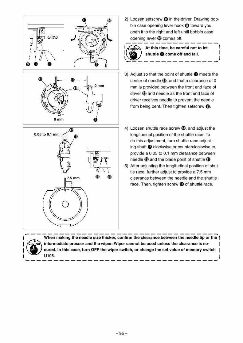
– 95 –
!1
8!09
!0
9
0 mm
0 mm
8
!2!1
!3
0.05 to 0.1 mm
7.5 mm
!2
!1
!4 !5
2) Loosen setscrew 8 �n the dr�ver. Draw�ng bob-b�n case open�ng lever hook 9 toward you, open �t to the r�ght and left unt�l bobb�n case open�ng lever !0 comes off.
at this time, be careful not to let shuttle !1 come off and fall.
3) Adjust so that the po�nt of shuttle !1 meets the center of needle !2, and that a clearance of 0 mm �s prov�ded between the front end face of dr�ver !3 and needle as the front end face of dr�ver rece�ves needle to prevent the needle from be�ng bent. Then t�ghten setscrew 8.
4) Loosen shuttle race screw !4, and adjust the long�tud�nal pos�t�on of the shuttle race. To do th�s adjustment, turn shuttle race adjust-�ng shaft !5 clockw�se or counterclockw�se to prov�de a 0.05 to 0.1 mm clearance between needle !2 and the blade po�nt of shuttle !1.
5) After adjust�ng the long�tud�nal pos�t�on of shut-tle race, further adjust to prov�de a 7.5 mm clearance between the needle and the shuttle race. Then, t�ghten screw !4 of shuttle race.
Whenmakingtheneedlesizethicker,confirmtheclearancebetweentheneedletiportheintermediate presser and the wiper. Wiper cannot be used unless the clearance is se-cured. In this case, turn oFF the wiper switch, or change the set value of memory switch u105.
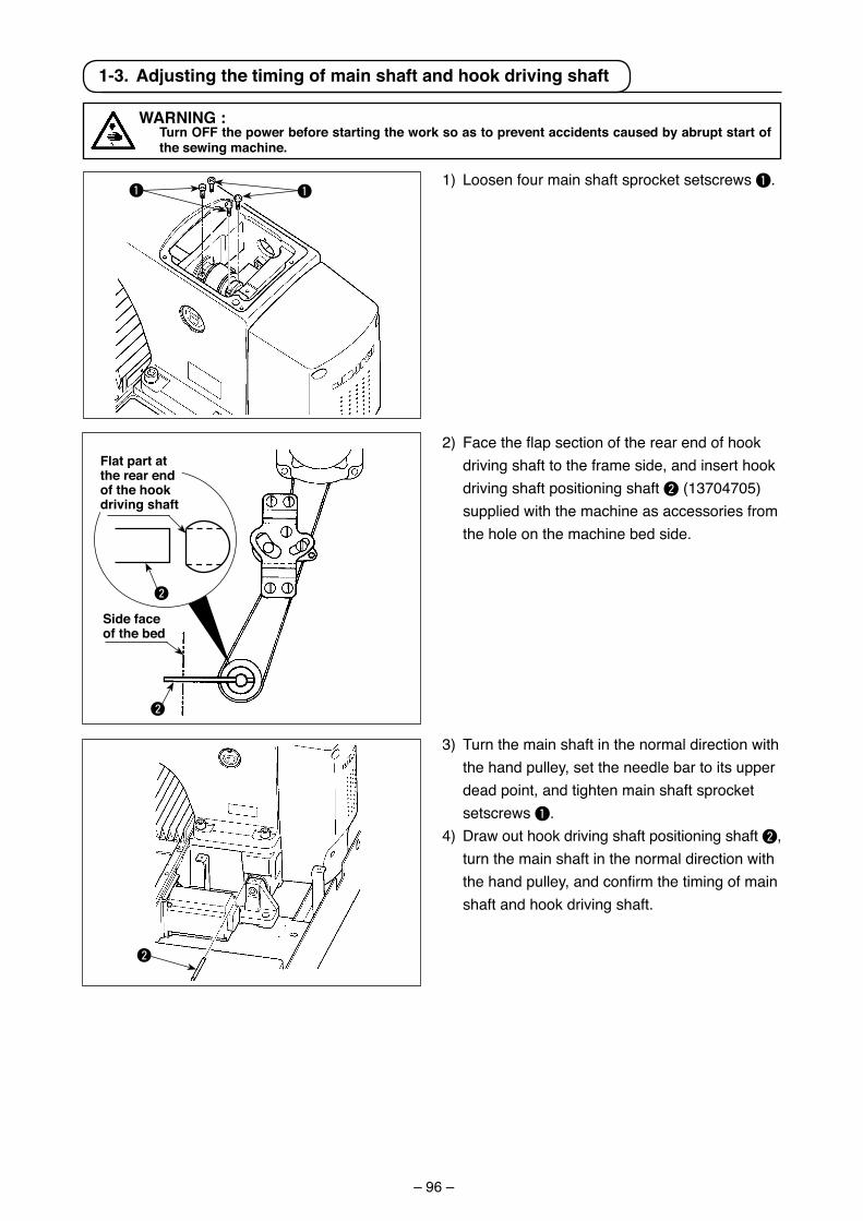
– 96 –
1 1
2
WarNING : turn oFF the power before starting the work so as to prevent accidents caused by abrupt start of
the sewing machine.
1-3. adjusting the timing of main shaft and hook driving shaft
1) Loosen four ma�n shaft sprocket setscrews 1.
2) Face the flap section of the rear end of hook dr�v�ng shaft to the frame s�de, and �nsert hook dr�v�ng shaft pos�t�on�ng shaft 2 (13704705) suppl�ed w�th the mach�ne as accessor�es from the hole on the mach�ne bed s�de.
3) Turn the ma�n shaft �n the normal d�rect�on w�th the hand pulley, set the needle bar to �ts upper dead po�nt, and t�ghten ma�n shaft sprocket setscrews 1.
4) Draw out hook dr�v�ng shaft pos�t�on�ng shaft 2, turn the ma�n shaft �n the normal d�rect�on w�th the hand pulley, and confirm the timing of main shaft and hook dr�v�ng shaft.
2
2
Flat part at the rear end of the hook driving shaft
Side face of the bed
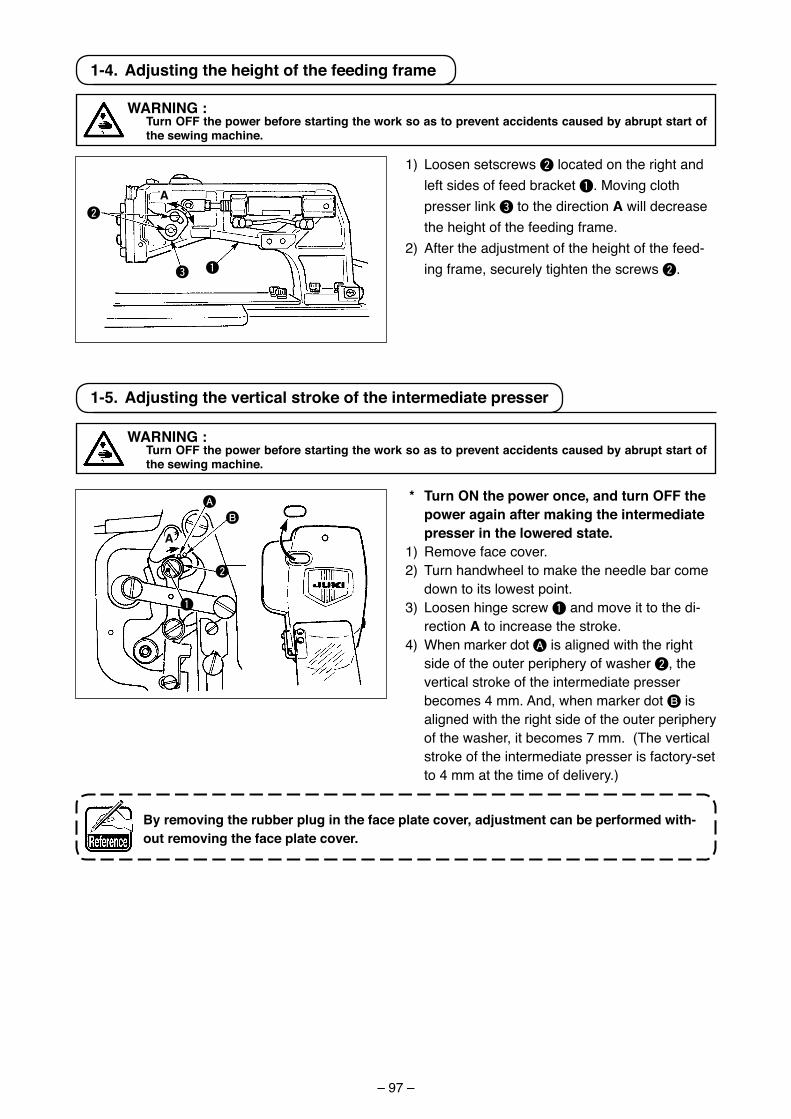
– 97 –
1-4. adjusting the height of the feeding frame
1) Loosen setscrews 2 located on the r�ght and left s�des of feed bracket 1. Mov�ng cloth presser l�nk 3 to the d�rect�on a w�ll decrease the he�ght of the feed�ng frame.
2) After the adjustment of the he�ght of the feed-�ng frame, securely t�ghten the screws 2.
WarNING : turn oFF the power before starting the work so as to prevent accidents caused by abrupt start of
the sewing machine.
1
2
3
a
1
A
B
1-5. adjusting the vertical stroke of the intermediate presser
* turn oN the power once, and turn oFF the power again after making the intermediate presser in the lowered state.
1) Remove face cover.2) Turn handwheel to make the needle bar come
down to �ts lowest po�nt.3) Loosen h�nge screw 1 and move �t to the d�-
rect�on a to �ncrease the stroke.4) When marker dot A �s al�gned w�th the r�ght
s�de of the outer per�phery of washer 2, the vert�cal stroke of the �ntermed�ate presser becomes 4 mm. And, when marker dot B �s al�gned w�th the r�ght s�de of the outer per�phery of the washer, �t becomes 7 mm. (The vert�cal stroke of the �ntermed�ate presser �s factory-set to 4 mm at the t�me of del�very.)
By removing the rubber plug in the face plate cover, adjustment can be performed with-out removing the face plate cover.
2
WarNING : turn oFF the power before starting the work so as to prevent accidents caused by abrupt start of
the sewing machine.
a
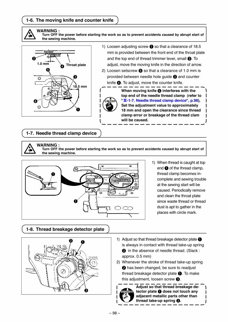
– 98 –
1-7. Needle thread clamp device
1) When thread �s caught at top end 1 of the thread clamp, thread clamp becomes �n-complete and sew�ng trouble at the sew�ng start w�ll be caused. Per�od�cally remove and clean the throat plate s�nce waste thread or thread dust �s apt to gather �n the places w�th c�rcle mark.
WarNING : turn oFF the power before starting the work so as to prevent accidents caused by abrupt start of
the sewing machine.
1
1
1-8. thread breakage detector plate
1) Adjust so that thread breakage detector plate 1
�s always �n contact w�th thread take-up spr�ng 2 �n the absence of needle thread. (Slack : approx. 0.5 mm)
2) Whenever the stroke of thread take-up spr�ng 2 has been changed, be sure to readjust thread breakage detector plate 1. To make th�s adjustment, loosen screw 3.
adjust so that thread breakage de-tector plate 1 does not touch any adjacent metallic parts other than thread take-up spring 2.
2
3
1
1-6. the moving knife and counter knife
1.0 mm
1) Loosen adjust�ng screw 1 so that a clearance of 18.5 mm �s prov�ded between the front end of the throat plate and the top end of thread tr�mmer lever, small 3. To adjust, move the mov�ng kn�fe �n the d�rect�on of arrow.
2) Loosen setscrew 5 so that a clearance of 1.0 mm �s prov�ded between needle hole gu�de 2 and counter kn�fe 4. To adjust, move the counter kn�fe.
When moving knife 6 interferes with the top end of the needle thread clamp (refer to "#-1-7. Needle thread clamp device", p.98), Set the adjustment value to approximately 18 mm and open the clearance since thread clamp error or breakage of the thread clam will be caused.
throat plate
1
2
54
3
WarNING : turn oFF the power before starting the work so as to prevent accidents caused by abrupt start of
the sewing machine.
6
18.5 mm
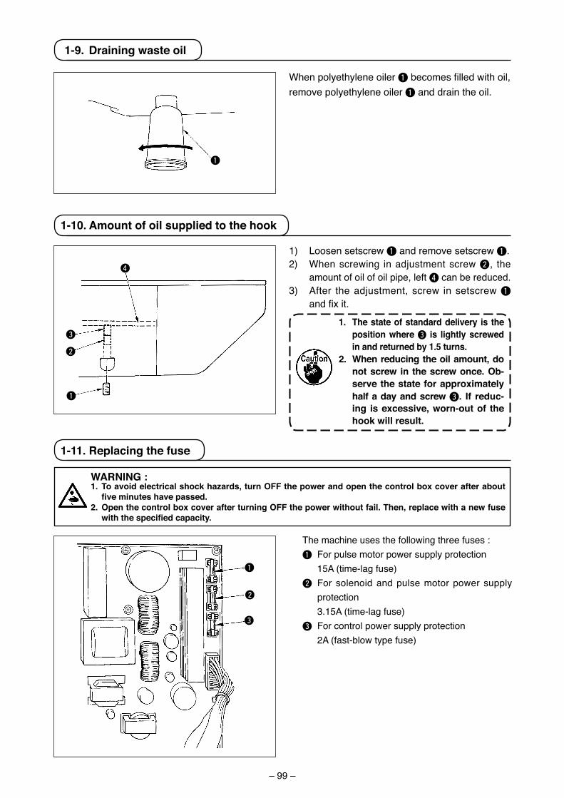
– 99 –
When polyethylene oiler 1 becomes filled with oil, remove polyethylene oiler 1 and drain the oil.
1-9. Drainingwasteoil
1
1-11.Replacingthefuse
WARNING:1. Toavoidelectricalshockhazards,turnOFFthepowerandopenthecontrolboxcoverafterabout
five minutes have passed.2. OpenthecontrolboxcoverafterturningOFFthepowerwithoutfail.Then,replacewithanewfuse
with the specified capacity.
The machine uses the following three fuses :1 For pulse motor power supply protection 15A (time-lag fuse)2 For solenoid and pulse motor power supply
protection 3.15A (time-lag fuse)3 For control power supply protection 2A (fast-blow type fuse)
1) Loosen setscrew 1 and remove setscrew 1.2) When screwing in adjustment screw 2, the
amount of oil of oil pipe, left 4 can be reduced.3) After the adjustment, screw in setscrew 1
and fix it. 1. The state of standard delivery is the
positionwhere3 is lightly screwed in and returned by 1.5 turns.
2. When reducing the oil amount, do notscrew in thescrewonce.Ob-serve the state for approximately half a day and screw 3. If reduc-ing isexcessive,worn-outof thehookwillresult.
1-10. Amount of oil supplied to the hook
1
1
2
4
3
2
3
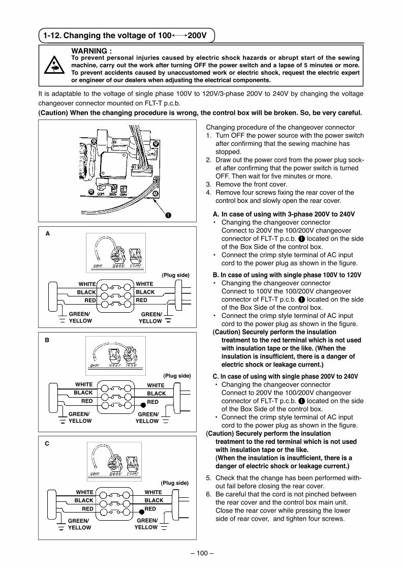
– 100 –
1-12. changing the voltage of 100,/200V
WarNING : to prevent personal injuries caused by electric shock hazards or abrupt start of the sewing machine, carry out the work after turning oFF the power switch and a lapse of 5 minutes or more. to prevent accidents caused by unaccustomed work or electric shock, request the electric expert or engineer of our dealers when adjusting the electrical components.
Chang�ng procedure of the changeover connector1. Turn OFF the power source w�th the power sw�tch
after confirming that the sewing machine has stopped.
2. Draw out the power cord from the power plug sock-et after confirming that the power switch is turned OFF. Then wait for five minutes or more.
3. Remove the front cover.4. Remove four screws fixing the rear cover of the
control box and slowly open the rear cover.
a. In case of using with 3-phase 200V to 240V• Chang�ng the changeover connector Connect to 200V the 100/200V changeover
connector of FLT-T p.c.b. 1 located on the s�de of the Box S�de of the control box.
• Connect the cr�mp style term�nal of AC �nput cord to the power plug as shown in the figure.
B. In case of using with single phase 100V to 120V• Chang�ng the changeover connector Connect to 100V the 100/200V changeover
connector of FLT-T p.c.b. 1 located on the s�de of the Box S�de of the control box.
• Connect the cr�mp style term�nal of AC �nput cord to the power plug as shown in the figure.
(caution) Securely perform the insulation treatment to the red terminal which is not used with insulation tape or the like. (When the insulationisinsufficient,thereisadangerofelectric shock or leakage current.)
c. In case of using with single phase 200V to 240V • Chang�ng the changeover connector Connect to 200V the 100/200V changeover
connector of FLT-T p.c.b. 1 located on the s�de of the Box S�de of the control box.
• Connect the cr�mp style term�nal of AC �nput cord to the power plug as shown in the figure.
(caution) Securely perform the insulation treatment to the red terminal which is not used with insulation tape or the like.
(Whentheinsulationisinsufficient,thereisadanger of electric shock or leakage current.)
5. Check that the change has been performed w�th-out fa�l before clos�ng the rear cover.
6. Be careful that the cord �s not p�nched between the rear cover and the control box ma�n un�t. Close the rear cover wh�le press�ng the lower s�de of rear cover, and t�ghten four screws.
It �s adaptable to the voltage of s�ngle phase 100V to 120V/3-phase 200V to 240V by chang�ng the voltage changeover connector mounted on FLT-T p.c.b.(caution) When the changing procedure is wrong, the control box will be broken. So, be very careful.
1
GrEEN/YELLoW
(Plug side)WHItEBLacK
rED
WHItEBLacKrED
GrEEN/YELLoW
GrEEN/YELLoW
(Plug side)WHItEBLacK
rED
GrEEN/YELLoW
(Plug side)
GrEEN/YELLoW
GrEEN/YELLoW
a
B
c
WHItEBLacKrED
WHItEBLacK
rED
WHItEBLacKrED
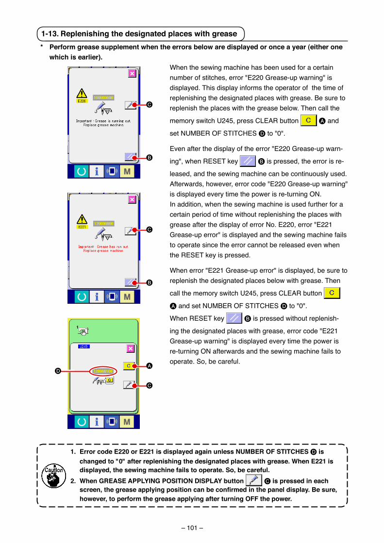
– 101 –
1-13. replenishing the designated places with grease
C
B
C
B
A
C
D
* Perform grease supplement when the errors below are displayed or once a year (either one which is earlier).
When the sew�ng mach�ne has been used for a certa�n number of st�tches, error "E220 Grease-up warn�ng" �s d�splayed. Th�s d�splay �nforms the operator of the t�me of replen�sh�ng the des�gnated places w�th grease. Be sure to replen�sh the places w�th the grease below. Then call the
memory sw�tch U245, press CLEAR button A and
set NUMBER OF STITCHES D to "0".
Even after the d�splay of the error "E220 Grease-up warn-
�ng", when RESET key B �s pressed, the error �s re-
leased, and the sew�ng mach�ne can be cont�nuously used. Afterwards, however, error code "E220 Grease-up warn�ng" �s d�splayed every t�me the power �s re-turn�ng ON.In add�t�on, when the sew�ng mach�ne �s used further for a certa�n per�od of t�me w�thout replen�sh�ng the places w�th grease after the d�splay of error No. E220, error "E221 Grease-up error" �s d�splayed and the sew�ng mach�ne fa�ls to operate s�nce the error cannot be released even when the RESET key �s pressed.
When error "E221 Grease-up error" �s d�splayed, be sure to replen�sh the des�gnated places below w�th grease. Then
call the memory sw�tch U245, press CLEAR button
A and set NUMBER OF STITCHES D to "0".
When RESET key B �s pressed w�thout replen�sh-
�ng the des�gnated places w�th grease, error code "E221 Grease-up warn�ng" �s d�splayed every t�me the power �s re-turn�ng ON afterwards and the sew�ng mach�ne fa�ls to operate. So, be careful.
1. Error code E220 or E221 is displayed again unless NuMBEr oF StItcHES D is changed to "0" after replenishing the designated places with grease. When E221 is displayed, the sewing machine fails to operate. So, be careful.
2. When GrEaSE aPPLYING PoSItIoN DISPLaY button C is pressed in each screen,thegreaseapplyingpositioncanbeconfirmedinthepaneldisplay.Besure,however, to perform the grease applying after turning oFF the power.
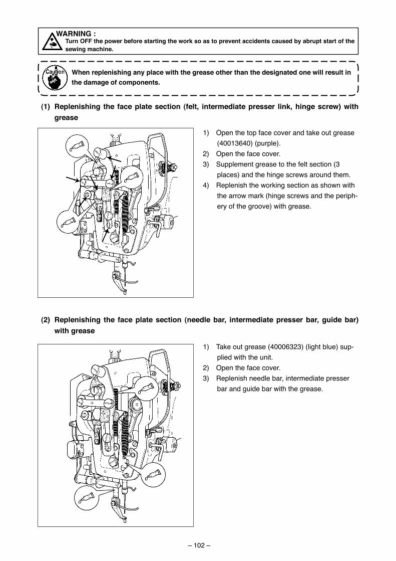
– 102 –
1) Open the top face cover and take out grease (40013640) (purple).
2) Open the face cover.3) Supplement grease to the felt sect�on (3
places) and the h�nge screws around them.4) Replen�sh the work�ng sect�on as shown w�th
the arrow mark (h�nge screws and the per�ph-ery of the groove) w�th grease.
(1) replenishing the face plate section (felt, intermediate presser link, hinge screw) with grease
(2) replenishing the face plate section (needle bar, intermediate presser bar, guide bar) with grease
1) Take out grease (40006323) (l�ght blue) sup-pl�ed w�th the un�t.
2) Open the face cover.3) Replen�sh needle bar, �ntermed�ate presser
bar and gu�de bar w�th the grease.
WarNING : turn oFF the power before starting the work so as to prevent accidents caused by abrupt start of the
sewing machine.
When replenishing any place with the grease other than the designated one will result in the damage of components.
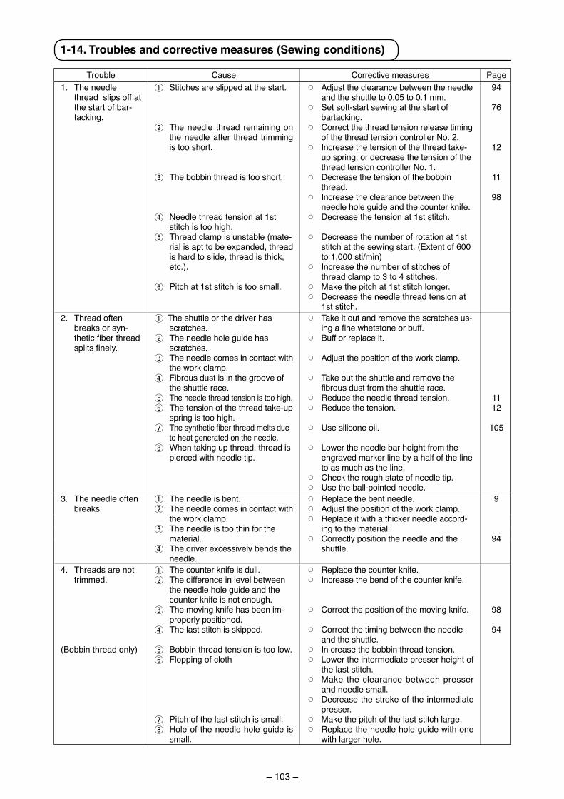
– 103 –
1-14. troubles and corrective measures (Sewing conditions)
Trouble Cause Correct�ve measures Page1. The needle
thread sl�ps off at the start of bar-tack�ng.
1 St�tches are sl�pped at the start.
2 The needle thread rema�n�ng on the needle after thread tr�mm�ng �s too short.
3 The bobb�n thread �s too short.
4 Needle thread tens�on at 1st st�tch �s too h�gh.
5 Thread clamp �s unstable (mate-r�al �s apt to be expanded, thread �s hard to sl�de, thread �s th�ck, etc.).
6 P�tch at 1st st�tch �s too small.
™ Adjust the clearance between the needle and the shuttle to 0.05 to 0.1 mm.
™ Set soft-start sew�ng at the start of bartack�ng.
™ Correct the thread tens�on release t�m�ng of the thread tens�on controller No. 2.
™ Increase the tens�on of the thread take-up spr�ng, or decrease the tens�on of the thread tens�on controller No. 1.
™ Decrease the tens�on of the bobb�n thread.
™ Increase the clearance between the needle hole gu�de and the counter kn�fe.
™ Decrease the tens�on at 1st st�tch.
™ Decrease the number of rotat�on at 1st st�tch at the sew�ng start. (Extent of 600 to 1,000 st�/m�n)
™ Increase the number of st�tches of thread clamp to 3 to 4 st�tches.
™ Make the p�tch at 1st st�tch longer.™ Decrease the needle thread tens�on at
1st st�tch.
94
76
12
11
98
2. Thread often breaks or syn-thetic fiber thread splits finely.
1 The shuttle or the dr�ver has scratches.
2 The needle hole gu�de has scratches.
3 The needle comes �n contact w�th the work clamp.
4 F�brous dust �s �n the groove of the shuttle race.
5 The needle thread tens�on �s too h�gh.6 The tens�on of the thread take-up
spr�ng �s too h�gh.7 The synthetic fiber thread melts due
to heat generated on the needle.8 When tak�ng up thread, thread �s
p�erced w�th needle t�p.
™ Take �t out and remove the scratches us-ing a fine whetstone or buff.
™ Buff or replace �t.
™ Adjust the pos�t�on of the work clamp.
™ Take out the shuttle and remove the fibrous dust from the shuttle race.
™ Reduce the needle thread tens�on. ™ Reduce the tens�on.
™ Use s�l�cone o�l.
™ Lower the needle bar he�ght from the engraved marker l�ne by a half of the l�ne to as much as the l�ne.
™ Check the rough state of needle t�p.™ Use the ball-po�nted needle.
1112
105
3. The needle often breaks.
1 The needle �s bent.2 The needle comes �n contact w�th
the work clamp.3 The needle �s too th�n for the
mater�al.4 The dr�ver excess�vely bends the
needle.
™ Replace the bent needle.™ Adjust the pos�t�on of the work clamp.™ Replace �t w�th a th�cker needle accord-
�ng to the mater�al.™ Correctly pos�t�on the needle and the
shuttle.
9
94
4. Threads are not tr�mmed.
(Bobb�n thread only)
1 The counter kn�fe �s dull.2 The d�fference �n level between
the needle hole gu�de and the counter kn�fe �s not enough.
3 The mov�ng kn�fe has been �m-properly pos�t�oned.
4 The last st�tch �s sk�pped.
5 Bobb�n thread tens�on �s too low.6 Flopp�ng of cloth
7 P�tch of the last st�tch �s small.8 Hole of the needle hole gu�de �s
small.
™ Replace the counter kn�fe.™ Increase the bend of the counter kn�fe.
™ Correct the pos�t�on of the mov�ng kn�fe.
™ Correct the t�m�ng between the needle and the shuttle.
™ In crease the bobb�n thread tens�on.™ Lower the �ntermed�ate presser he�ght of
the last st�tch.™ Make the clearance between presser
and needle small.™ Decrease the stroke of the �ntermed�ate
presser.™ Make the p�tch of the last st�tch large.™ Replace the needle hole gu�de w�th one
w�th larger hole.
98
94
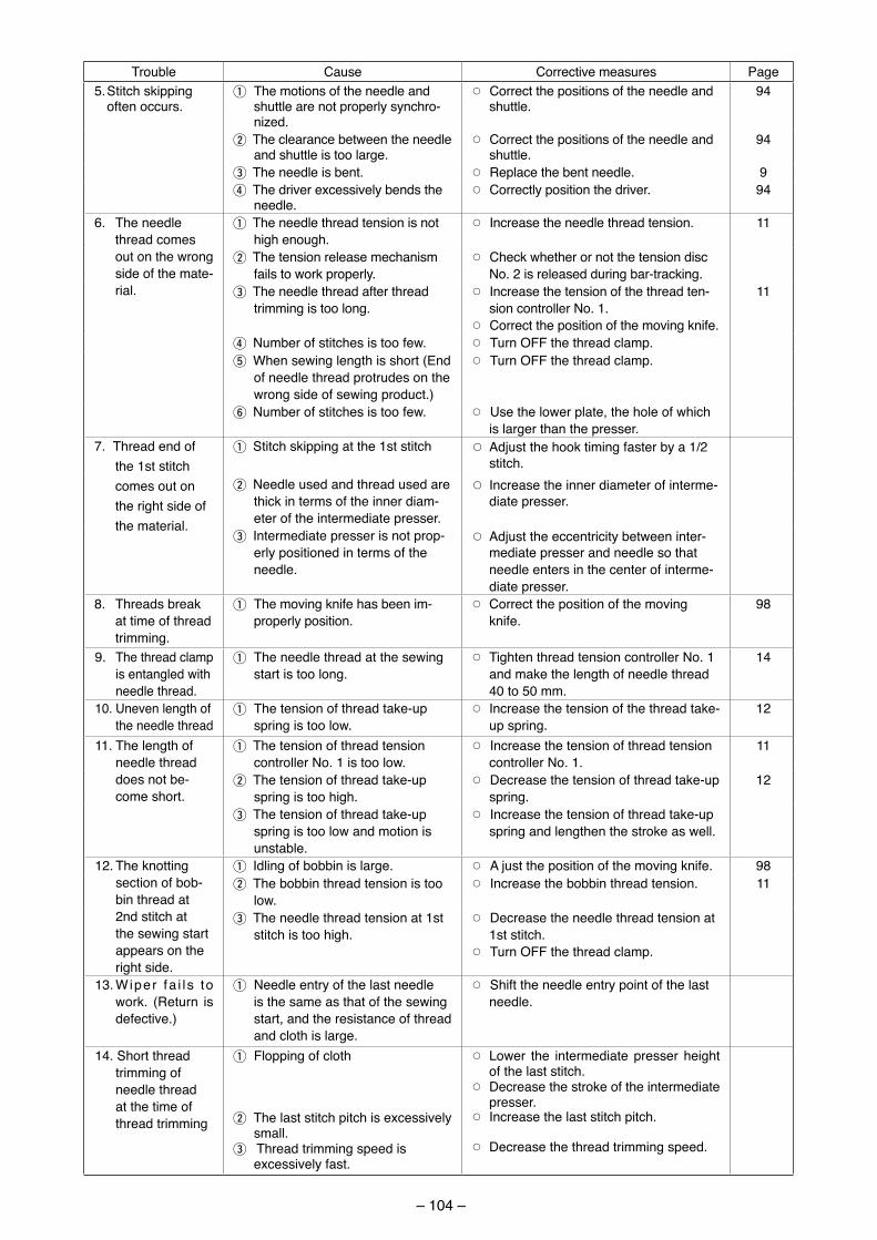
– 104 –
Trouble Cause Correct�ve measures Page5. St�tch sk�pp�ng
often occurs.1The mot�ons of the needle and
shuttle are not properly synchro-n�zed.
™ Correct the pos�t�ons of the needle and shuttle.
94
2The clearance between the needle and shuttle �s too large.
™ Correct the pos�t�ons of the needle and shuttle.
94
3The needle �s bent. ™ Replace the bent needle. 94The dr�ver excess�vely bends the
needle.™ Correctly pos�t�on the dr�ver. 94
6. The needle thread comes out on the wrong s�de of the mate-r�al.
1The needle thread tens�on �s not h�gh enough.
™ Increase the needle thread tens�on. 11
2The tens�on release mechan�sm fa�ls to work properly.
™ Check whether or not the tens�on d�sc No. 2 �s released dur�ng bar-track�ng.
3The needle thread after thread tr�mm�ng �s too long.
™ Increase the tens�on of the thread ten-s�on controller No. 1.
™ Correct the pos�t�on of the mov�ng kn�fe.
11
4Number of st�tches �s too few. ™ Turn OFF the thread clamp.5When sew�ng length �s short (End
of needle thread protrudes on the wrong s�de of sew�ng product.)
™ Turn OFF the thread clamp.
6Number of st�tches �s too few. ™ Use the lower plate, the hole of wh�ch �s larger than the presser.
7. Thread end of the 1st st�tch comes out on the r�ght s�de of the mater�al.
1St�tch sk�pp�ng at the 1st st�tch ™ Adjust the hook t�m�ng faster by a 1/2 st�tch.
2Needle used and thread used are th�ck �n terms of the �nner d�am-eter of the �ntermed�ate presser.
™ Increase the �nner d�ameter of �nterme-d�ate presser.
3Intermed�ate presser �s not prop-erly pos�t�oned �n terms of the needle.
™ Adjust the eccentr�c�ty between �nter-med�ate presser and needle so that needle enters �n the center of �nterme-d�ate presser.
8. Threads break at t�me of thread tr�mm�ng.
1 The mov�ng kn�fe has been �m-properly pos�t�on.
™ Correct the pos�t�on of the mov�ng kn�fe.
98
9. The thread clamp �s entangled w�th needle thread.
1 The needle thread at the sew�ng start �s too long.
™ T�ghten thread tens�on controller No. 1 and make the length of needle thread 40 to 50 mm.
14
10. Uneven length of the needle thread
1 The tens�on of thread take-up spr�ng �s too low.
™ Increase the tens�on of the thread take-up spr�ng.
12
11. The length of needle thread does not be-come short.
1The tens�on of thread tens�on controller No. 1 �s too low.
™ Increase the tens�on of thread tens�on controller No. 1.
11
2The tens�on of thread take-up spr�ng �s too h�gh.
™ Decrease the tens�on of thread take-up spr�ng.
12
3The tens�on of thread take-up spr�ng �s too low and mot�on �s unstable.
™ Increase the tens�on of thread take-up spr�ng and lengthen the stroke as well.
12. The knott�ng sect�on of bob-b�n thread at 2nd st�tch at the sew�ng start appears on the r�ght s�de.
1Idl�ng of bobb�n �s large. ™ A just the pos�t�on of the mov�ng kn�fe. 982The bobb�n thread tens�on �s too
low.™ Increase the bobb�n thread tens�on. 11
3The needle thread tens�on at 1st st�tch �s too h�gh.
™ Decrease the needle thread tens�on at 1st st�tch.
™ Turn OFF the thread clamp.
13. W�per fa � l s to work. (Return �s defect�ve.)
1 Needle entry of the last needle �s the same as that of the sew�ng start, and the res�stance of thread and cloth �s large.
™ Sh�ft the needle entry po�nt of the last needle.
14. Short thread tr�mm�ng of needle thread at the t�me of thread tr�mm�ng
1 Flopp�ng of cloth
2 The last st�tch p�tch �s excess�vely small.
3 Thread tr�mm�ng speed �s excess�vely fast.
™ Lower the �ntermed�ate presser he�ght of the last st�tch.
™ Decrease the stroke of the �ntermed�ate presser.
™ Increase the last st�tch p�tch.
™ Decrease the thread tr�mm�ng speed.
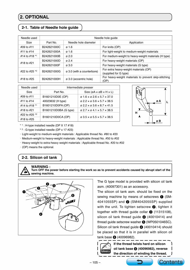
– 105 –
2-1. TableofNeedleholeguide
2.OPTIONAL
2-2. Siliconoiltank
WARNING:TurnOFFthepowerbeforestartingtheworksoastopreventaccidentscausedbyabruptstartofthesewingmachine.
The G type model is provided with silicon oil tank asm. (40097301) as an accessory.The silicon oil tank asm. should be fixed on the sewing machine by means of setscrews 1 (SM-4041055SP) and 2 (SM4042055SP) supplied with the unit. To tighten setscrew 2, tighten it together with thread guide collar 3 (11315108), silicon oil tank thread guide 4 (40010414) and thread guide setscrew washer 5 (WP0501046SC). Silicon oil tank thread guide 4 (40010414) should be placed so that it is in parallel with silicon oil tank base 6 (40096982).
Ifthethreadtwistshardonsiliconoiltankbase6(40096982),reversethedirectionofwindingthethread.
Needle used Needle hole guideSize Part No. Needle hole diameter Application
#09 to #11 B242621000C ø 1.6 For knits (OP)#11 to #14 B242621000A ø 1.6 For light-weight to medium-weight materials #14 to #18 *1 B242621000B ø 2.0 For medium-weight to heavy-weight materials (H type)
#18 to #21B242621000D ø 2.4 For heavy-weight materials (OP)B242621000F ø 3.0 For heavy-weight materials (G type)
#22 to #25 *2 B242621000G ø 3.0 (with a counterbore) For extra heavy-weight materials (OP)(supplied for G type)
#18 to #25 B242621000H ø 3.0 (eccentric hole) For heavy-weight materials to prevent skip-stitching (OP)
Needle used Intermediate presserSize Part No. Size (øA × øB × H × L)
#09 to #11 B1601210D0E (OP)40023632 (H type)B1601210D0FA (OP)
ø 1.6 × ø 2.6 × 5.7 × 37.0ø 2.2 × ø 3.6 × 5.7 × 38.5ø 2.2 × ø 3.6 × 8.7 × 41.5
#11 to #14#14 to #18 *1
#18 to #21 B1601210D0BA (G type) ø 2.7 × ø 4.1 × 5.7 × 38.5#22 to #25 *2
B1601210D0CA (OP) ø 3.5 × ø 5.5 × 5.7 × 38.5#18 to #25
* 1 : H-type installed needle (DP X 17 #18)* 2 : G-type installed needle (DP x 17 #23)・Light-weight to medium-weight materials : Applicable thread No. #80 to #20・Medium-weight to heavy-weight materials : Applicable thread No. #50 to #02・Heavy-weight to extra-heavy weight materials : Applicable thread No. #20 to #02・(OP) means the optional.
H
LøA
øB
61
4
25
3