Embed Size (px)
Citation preview
8/12/2019 AMR(GBSS14.0_01)
http://slidepdf.com/reader/full/amrgbss14001 1/41
AMRGBSS14.0
Feature Parameter Description
Issue 01
Date 2012-04-28
HUAWEI TECHNOLOGIES CO., LTD.

8/12/2019 AMR(GBSS14.0_01)
http://slidepdf.com/reader/full/amrgbss14001 2/41
Copyright © Huawei Technologies Co., Ltd. 2012. All rights reserved.
No part of this document may be reproduced or transmitted in any form or by any means without prior
written consent of Huawei Technologies Co., Ltd.
Trademarks and Permissions
and other Huawei trademarks are trademarks of Huawei Technologies Co., Ltd.
All other trademarks and trade names mentioned in this document are the property of their respective
holders.
Notice
The purchased products, services and features are stipulated by the contract made between Huawei and
the customer. All or part of the products, services and features described in this document may not be
within the purchase scope or the usage scope. Unless otherwise specified in the contract, all statements,
information, and recommendations in this document are provided "AS IS" without warranties, guarantees orrepresentations of any kind, either express or implied.
The information in this document is subject to change without notice. Every effort has been made in the
preparation of this document to ensure accuracy of the contents, but all statements, information, and
recommendations in this document do not constitute the warranty of any kind, express or implied.
Huawei Technologies Co., Ltd.
Address: Huawei Industrial Base
Bantian, Longgang
Shenzhen 518129
People's Republic of China
Website: http://www.huawei.com
Email: [email protected]
8/12/2019 AMR(GBSS14.0_01)
http://slidepdf.com/reader/full/amrgbss14001 3/41
GSM BSS
AMR Contents
Issue Draft A (2012-04-28) Huawei Proprietary and Confidential
Copyright © Huawei Technologies Co., Ltd
i
Contents
1 About This Document .............................................................................................................. 1-1 1.1 Scope ............................................................................................................................................ 1-1 1.2 Intended Audience......................................................................................................................... 1-1 1.3 Change History .............................................................................................................................. 1-1
2 Overview...................................................................................................................................... 2-1 3 Technical Description .............................................................................................................. 3-1
3.1 Inband Signaling............................................................................................................................ 3-1 3.2 Speech Rate Adjustment ............................................................................................................... 3-2 3.3 AMR Coding Rate Threshold Adaptive Adjustment ....................................................................... 3-4 3.4 Um Interface Speech Frame Repairing ......................................................................................... 3-5 3.5 AMR Power Control ....................................................................................................................... 3-5 3.6 AMR FR/HR Dynamic Adjustment ................................................................................................. 3-6 3.7 E-CODER ...................................................................................................................................... 3-6 3.8 AMR Radio Link Timer .................................................................................................................. 3-6
4 Related Features ....................................................................................................................... 4-1 5 Impact on the Network............................................................................................................. 5-1
5.1 AMR FR ......................................................................................................................................... 5-1 5.1.1 Impact on System Capacity .................................................................................................. 5-1 5.1.2 Impact on Network Performance .......................................................................................... 5-1
5.2 AMR HR ........................................................................................................................................ 5-1 5.2.1 Impact on System Capacity .................................................................................................. 5-1 5.2.2 Impact on Network Performance .......................................................................................... 5-1
5.3 AMR Power Control ....................................................................................................................... 5-1 5.3.1 Impact on System Capacity .................................................................................................. 5-1 5.3.2 Impact on Network Performance .......................................................................................... 5-1
5.4 AMR Coding Rate Threshold Adaptive Adjustment ....................................................................... 5-1 5.4.1 Impact on System Capacity .................................................................................................. 5-1 5.4.2 Impact on Network Performance .......................................................................................... 5-2
5.5 Um Interface Speech Frame Repairing ......................................................................................... 5-2 5.5.1 Impact on System Capacity .................................................................................................. 5-2 5.5.2 Impact on Network Performance .......................................................................................... 5-2
5.6 AMR Radio Link Timer .................................................................................................................. 5-2 5.6.1 Impact on System Capacity .................................................................................................. 5-2 5.6.2 Impact on Network Performance .......................................................................................... 5-2
5.7 AMR FR/HR Dynamic Adjustment ................................................................................................. 5-2 5.7.1 Impact on System Capacity .................................................................................................. 5-2 5.7.2 Impact on Network Performance .......................................................................................... 5-2
6 Engineering Guidelines ........................................................................................................... 6-1

8/12/2019 AMR(GBSS14.0_01)
http://slidepdf.com/reader/full/amrgbss14001 4/41
GSM BSS
AMR Contents
Issue Draft A (2012-04-28) Huawei Proprietary and Confidential
Copyright © Huawei Technologies Co., Ltd
ii
6.1 When to Use AMR ......................................................................................................................... 6-1 6.1.1 AMR FR and AMR HR .......................................................................................................... 6-1 6.1.2 AMR Power Control .............................................................................................................. 6-1 6.1.3 AMR Coding Rate Threshold Adaptive Adjustment .............................................................. 6-1 6.1.4 Um Interface Speech Frame Repairing ................................................................................ 6-1 6.1.5 AMR Radio Link Timer .......................................................................................................... 6-1 6.1.6 AMR FR/HR Dynamic Adjustment ........................................................................................ 6-1
6.2 Information to Be Collected ........................................................................................................... 6-1 6.2.1 AMR FR and AMR HR .......................................................................................................... 6-1 6.2.2 AMR Power Control .............................................................................................................. 6-1 6.2.3 AMR Coding Rate Threshold Adaptive Adjustment .............................................................. 6-2 6.2.4 Um Interface Speech Frame Repairing ................................................................................ 6-2 6.2.5 AMR Radio Link Timer .......................................................................................................... 6-2 6.2.6 AMR FR/HR Dynamic Adjustment ........................................................................................ 6-2
6.3 Network Planning .......................................................................................................................... 6-2 6.3.1 AMR FR and AMR HR .......................................................................................................... 6-2 6.3.2 AMR Power Control .............................................................................................................. 6-2 6.3.3 AMR Coding Rate Threshold Adaptive Adjustment .............................................................. 6-2 6.3.4 Um Interface Speech Frame Repairing ................................................................................ 6-3 6.3.5 AMR Radio Link Timer .......................................................................................................... 6-3 6.3.6 AMR FR/HR Dynamic Adjustment ........................................................................................ 6-3
6.4 Deploying AMR FR and AMR HR .................................................................................................. 6-3 6.5 Deploying AMR Power Control ...................................................................................................... 6-3 6.6 Deploying AMR Coding Rate Threshold Adaptive Adjustment...................................................... 6-3 6.7 Deploying Um Interface Speech Frame Repairing ........................................................................ 6-3 6.8 Deploying AMR Radio Link Timer ................................................................................................. 6-3 6.9 Deploying AMR FR/HR Dynamic Adjustment ............................................................................... 6-3
7 Performance Optimization ..................................................................................................... 7-1 7.1 AMR FR and AMR HR ................................................................................................................... 7-1 7.2 AMR Power Control ....................................................................................................................... 7-1 7.3 AMR Coding Rate Threshold Adaptive Adjustment ....................................................................... 7-1 7.4 Um Interface Speech Frame Repairing ......................................................................................... 7-1 7.5 AMR Radio Link Timer .................................................................................................................. 7-1 7.6 AMR FR/HR Dynamic Adjustment ................................................................................................. 7-2
8 Parameters.................................................................................................................................. 8-1 9 Counters ...................................................................................................................................... 9-1 10 Glossary .................................................................................................................................. 10-1 11 Reference Documents ......................................................................................................... 11-1

8/12/2019 AMR(GBSS14.0_01)
http://slidepdf.com/reader/full/amrgbss14001 5/41
GSM BSS
AMR 1 About This Document
Issue Draft A (2012-04-28) Huawei Proprietary and Confidential
Copyright © Huawei Technologies Co., Ltd
1-1
1 About This Document
1.1 Scope
This document describes the AMR feature. It describes inband signaling, adaptive multirate (AMR)speech rate adjustment, AMR Coding Rate Threshold Adaptive Adjustment, Um Interface Speech FrameRepairing, AMR Power Control, AMR FR/HR Dynamic Adjustment, enhanced coding (E-CODER), and AMR Radio Link Timer. It also includes feature dependencies, network impact, and engineeringguidelines.
1.2 Intended Audience
This document is intended for:
Personnel who need to understand the AMR feature
Personnel who work with Huawei GSM products
1.3 Change History
This section provides information on the changes in different document versions.
There are two types of changes, which are defined as follows:
Feature change: refers to a change in the AMR feature of a specific product version.
Editorial change: refers to a change in wording or the addition of information that was not described inthe earlier version.
Document Issues
The document issue is as follows:
01 (2012-04-28)
Draft A (2012-02-15)
01 (2012-04-28)
This is the first release of GBSS14.0.
Compared with issue draft A (2012-02-15) of GBSS14.0, issue 01 (2012-04-28) of GBSS14.0 has nochange.
Draft A (2012-02-15)
This is a draft.
Compared with issue 02 (2011-07-15) of GBSS13.0, draft A (2012-02-15) of GBSS14.0 incorporates thechanges described in the following table.
Change Type Change Description Parameter Change
Feature change None None
Editorial change Added the following chapters:
Chapter 4 Related Features
Chapter 5 Impact on the Network
Chapter 6 Engineering Guidelines
None

8/12/2019 AMR(GBSS14.0_01)
http://slidepdf.com/reader/full/amrgbss14001 6/41
GSM BSS
AMR 1 About This Document
Issue Draft A (2012-04-28) Huawei Proprietary and Confidential
Copyright © Huawei Technologies Co., Ltd
1-2

8/12/2019 AMR(GBSS14.0_01)
http://slidepdf.com/reader/full/amrgbss14001 7/41
GSM BSS
AMR 2 Overview
Issue Draft A (2012-04-28) Huawei Proprietary and Confidential
Copyright © Huawei Technologies Co., Ltd
2-1
2 Overview
AMR is an adaptive multi-rate voice coding/decoding, which is termed full-rate speech version 3 andhalf-rate speech version 3 in GSM specifications. AMR enables the BTS and the MS to automatically
select an appropriate coding/decoding rate from the specified ACS according to the interference level inthe radio environment. This enhances the capability and the speech quality of the wirelesscommunication system.
AMR is classified into AMR FR and AMR HR. AMR specifies eight speech coding rates. Table 2-1 liststhe speech coding rates supported by AMR FR and AMR HR. (GBFD-115501 AMR FR, GBFD-115502 AMR HR)
Table 2-1 AMR speech coding rates
Coding Rate AMR FR AMR HR
4.75 kbit/s √ √
5.15 kbit/s √ √
5.90 kbit/s √ √
6.70 kbit/s √ √
7.40 kbit/s √ √
7.95 kbit/s √ √
10.2 kbit/s √ -
12.2 kbit/s √ -
NOTE-: not supported
√: supported
When SERVICEMODE of the BTS is set to IP or HDLC, Huawei BSS supports the AMR coding rate of 7.95 kbit/s.When SERVICEMODE of the BTS is set to TDM, Huawei BSS does not support the AMR HR coding rate of 7.95 kbit/s.
As listed in Table 2-1, the coding rates of 12.2 kbit/s and 10.2 kbit/s are supported by only the AMR FRchannel. The other six types of coding rates are supported by both the AMR FR channel and the AMRHR channel.
Each ACS contains a maximum of four coding schemes. One coding scheme corresponds to one
speech coding rate.
For an AMR FR call, the ACS contains a maximum of four speech coding rates of the eight rates listedin Table 2-1.
For an AMR HR call, the ACS contains a maximum of four speech coding rates of the six rates listed inTable 2-1.
When AMR is enabled on the network, the BSC selects an ACS and then a coding scheme from the ACS during the call establishment or the handover procedure. Meanwhile, the MS and the BTScontinuously measure the receive level, receive quality, and carrier-to-interference ratio (CIR). According to the measurement results, the MS and the BTS continuously evaluate the interferencelevel in the radio environment. The BTS then adjusts the speech coding rates of the MS and the BTSaccording to the evaluated interference level through the inband signaling.
8/12/2019 AMR(GBSS14.0_01)
http://slidepdf.com/reader/full/amrgbss14001 8/41
GSM BSS
AMR 3 Technical Description
Issue Draft A (2012-04-28) Huawei Proprietary and Confidential
Copyright © Huawei Technologies Co., Ltd
3-1
3 Technical Description
3.1 Inband Signaling
Inband signaling is a type of signaling through which user data and control information are transmittedon the same channel. In this document, the inband signaling refers to the AMR control information suchas the CMR and CMI that is transmitted through certain bits in the header of the Transcoder and Rate Adaptor Unit (TRAU) frame.
During a call, the MS and the BTS continuously measure the interference level experienced by thesignals and analyze the measurement results. Based on the measurement results, the AMR controlinformation is then exchanged through the inband signaling to enable the BTS to adjust the speechcoding rate involved in the ongoing speech service.
The AMR control information is transmitted through certain bits in the header of the TRAU frame. The AMR control information can be classified into the following types:
Downlink Codec Mode Request (DL CMR): The DL CMR occupies two bits in the header of the TRAUframe. It is used by the MS to send the recommended DL coding scheme to the BTS.
Downlink Codec Mode Indication (DL CMI): The DL CMI occupies two bits in the header of the TRAUframe. It is used by the BTS to send the current DL coding scheme to the MS.
Uplink Codec Mode Command (UL CMC): The UL CMC occupies two bits in the header of the TRAUframe. It is used by the BTS to send the UL coding scheme that should be used by the MS to the MS.
Uplink Codec Mode Indication (UL CMI): The UL CMI occupies two bits in the header of the TRAU frame.It is used by the MS to send the current UL coding scheme to the BTS.
Uplink Maximum Codec Mode Command (UL Max CMC): The UL Max CMC occupies three bits in theheader of the TRAU frame.
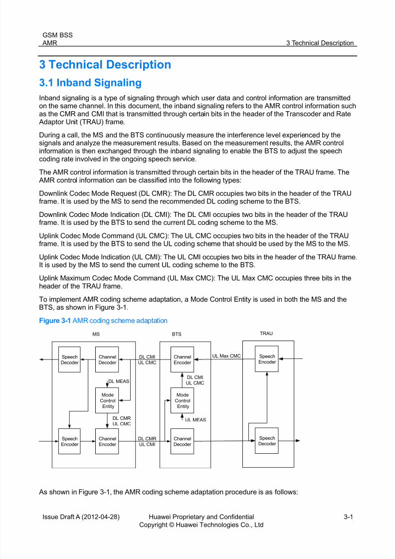
To implement AMR coding scheme adaptation, a Mode Control Entity is used in both the MS and theBTS, as shown in Figure 3-1.
Figure 3-1 AMR coding scheme adaptation
Speech
Decoder
Channel
Decoder
Mode
Control
Entity
Speech
Encoder
Channel
Encoder
MS
DL MEAS
DL CMR
UL CMC
Channel
Encoder
Mode
Control
Entity
Channel
Decoder
BTS
DL CMI
UL CMC
DL CMI
UL CMC
DL CMR
UL CMI
UL MEAS
Speech
Encoder
Speech
Decoder
TRAU
UL Max CMC
As shown in Figure 3-1, the AMR coding scheme adaptation procedure is as follows:
8/12/2019 AMR(GBSS14.0_01)
http://slidepdf.com/reader/full/amrgbss14001 9/41
GSM BSS
AMR 3 Technical Description
Issue Draft A (2012-04-28) Huawei Proprietary and Confidential
Copyright © Huawei Technologies Co., Ltd
3-2
Uplink direction
- The BTS measures the receive quality of the UL speech and generates the Uplink Measurement (ULMEAS).
- The Mode Control Entity of the BTS updates the UL CMC based on the UL MEAS generated by the
BTS.- The BTS instructs the MS to change the UL coding scheme through the UL CMC.
- The MS changes the UL coding scheme as indicated by the UL CMC and then sends the UL CMI tothe BTS to inform the BTS of the new UL coding scheme.
Downlink direction
- The MS measures the receive quality of the DL speech and generates the Downlink Measurement (DLMEAS). The Mode Control Entity of the MS converts the DL MEAS into the recommended DL codingscheme. Then, the MS sends the recommended DL coding scheme to the BTS through the DL CMR.
- The Mode Control Entity of the BTS updates the DL speech coding scheme based on therecommended DL coding scheme sent from the MS.
-
The BTS instructs the MS to use the new DL coding scheme through the DL CMI.
3.2 Speech Rate Adjustment
AMR speech rate adjustment is the process that the AMR coding scheme of a call on a channelfrequently changes to adapt to the variations of the interference level in the radio environment.
Each AMR coding scheme has an adjustment threshold, which is used to select the coding scheme thatis best suited to the CIR or Bit Error Rate (BER) of the interference level in the radio environment. Toavoid the constant changes of the coding scheme, the process of hysteresis is introduced. The value ofthe threshold ranges from 0 to 63. Value 1 indicates 0.5 dB, and value 2 indicates 1 dB. The rest may bededuced by analogy. The value of the hysteresis ranges from 0 to 15. The hysteresis value complementsthe threshold.
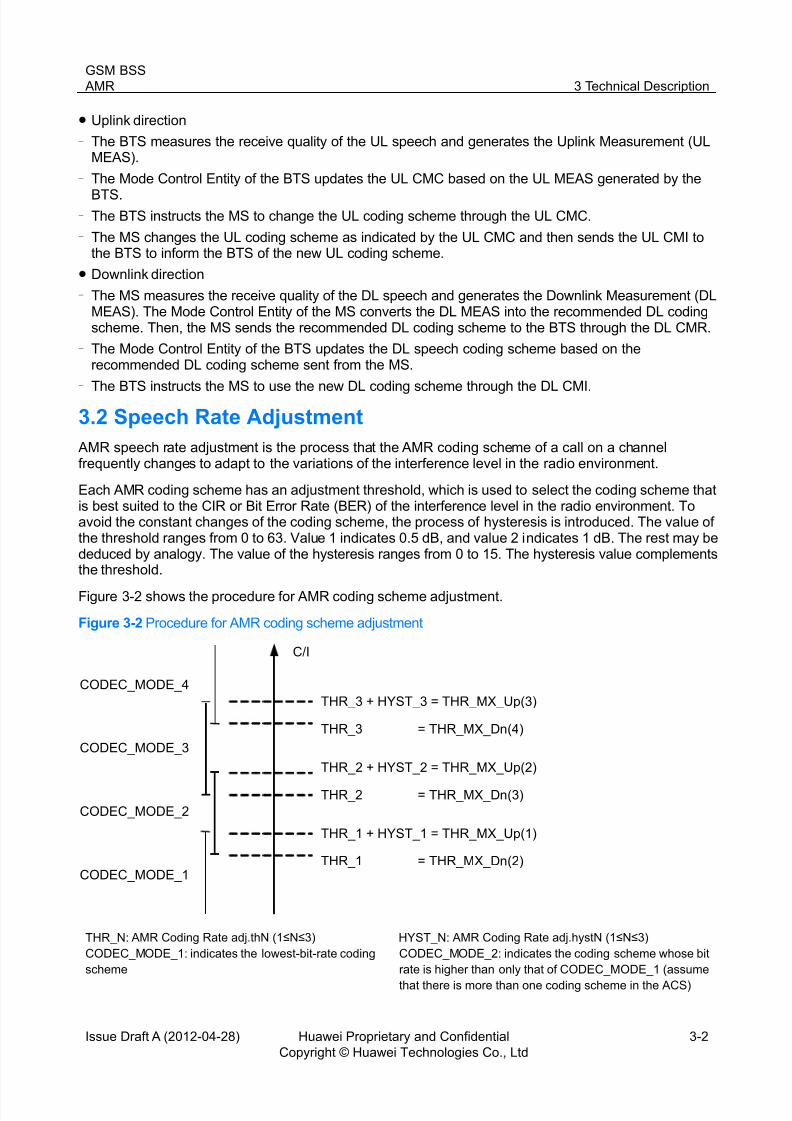
Figure 3-2 shows the procedure for AMR coding scheme adjustment.
Figure 3-2 Procedure for AMR coding scheme adjustment
CODEC_MODE_4
CODEC_MODE_3
CODEC_MODE_2
CODEC_MODE_1
C/I
THR_1 + HYST_1 = THR_MX_Up(1)
THR_1 = THR_MX_Dn(2)
THR_2 = THR_MX_Dn(3)
THR_2 + HYST_2 = THR_MX_Up(2)
THR_3 = THR_MX_Dn(4)
THR_3 + HYST_3 = THR_MX_Up(3)
THR_N: AMR Coding Rate adj.thN (1≤N≤3) HYST_N: AMR Coding Rate adj.hystN (1≤N≤3) CODEC_MODE_1: indicates the lowest-bit-rate coding
scheme
CODEC_MODE_2: indicates the coding scheme whose bit
rate is higher than only that of CODEC_MODE_1 (assume
that there is more than one coding scheme in the ACS)

8/12/2019 AMR(GBSS14.0_01)
http://slidepdf.com/reader/full/amrgbss14001 10/41
GSM BSS
AMR 3 Technical Description
Issue Draft A (2012-04-28) Huawei Proprietary and Confidential
Copyright © Huawei Technologies Co., Ltd
3-3
CODEC_MODE_3: indicates the coding scheme whose
bit rate is the second highest in the ACS (assume that
there are more than two coding schemes in the ACS)
CODEC_MODE_4: indicates the coding scheme whose bit
rate is the highest in the ACS (assume that there are four
coding schemes in the ACS)
Assume that the currently used coding scheme is CODEC_MODE_3. As shown in Figure 3-2, when theCIR is greater than THR_3 plus HYST_3, the coding scheme is changed to CODEC_MODE_4; whenthe CIR is smaller than THR_2, the coding scheme is changed to CODEC_MODE_2.
The procedure for AMR UL speech rate adjustment is similar to the procedure for AMR DL speech rateadjustment. The AMR UL coding scheme is adjusted by the BTS, and the AMR DL coding scheme isadjusted by the MS. Figure 3-3 shows the procedure through which the BTS adjusts the AMR UL codingscheme.
Figure 3-3 Procedure through which the BTS adjusts the AMR UL coding scheme
N
Y
N
Select the initial AMR
coding rate.
Start
Enable AMR rate
adjustment algorithm?
Perform filtering for C/I
or BER data.
Filter value >
(THR_N+HYST_N)?
Filter value <
THR_N-1?
Keep the codingrate unchanged.
MS must use the AMR coding
rate of a higher level.
MS must use the AMR coding
rate of a lower level.
Adjust the coding
rate.
End
Y
N
Y
THR_N: AMR UL Coding Rate adj.thN (1 ≤ N ≤ 3) HYST_N: AMR UL Coding Rate adj.hystN (1 ≤ N ≤ 3)

8/12/2019 AMR(GBSS14.0_01)
http://slidepdf.com/reader/full/amrgbss14001 11/41
GSM BSS
AMR 3 Technical Description
Issue Draft A (2012-04-28) Huawei Proprietary and Confidential
Copyright © Huawei Technologies Co., Ltd
3-4
The procedure through which the BTS adjusts the AMR UL coding scheme shown in Figure 3-3 isdescribed as follows:
1. During AMR FR call establishment, INITCDMDF specifies which coding scheme in ACTCDSETF should be used to make a call. During AMR HR call establishment, INITCDMDH specifies which
coding scheme in ACTCDSETH should be used to make a call.2. The RATECTRLSW parameter specifies whether the AMR speech rate is adjusted. The setting of
this parameter is described as follows:
− If this parameter is set to ALG1(Algorithm I), the BSC adjusts the AMR speech rate based on theCIR.
− If this parameter is set to ALG2(Algorithm II), the BSC adjusts the AMR speech rate based on theBit Error Rate (BER).
− If this parameter is set to NONE(None), the AMR coding rate adjustment is disabled.
3. If the RATECTRLSW parameter is set to ALG1(Algorithm I) or ALG2(Algorithm II), the AMRcoding scheme adapts to the change of the radio environment during the call according to theconfigured threshold and hysteresis.
The following description takes the adjustment of the AMR FR coding scheme as an example.
The currently used coding scheme is CODEC_MODE_1.
− If the filter value is greater than ULTHF1 plus ULHYSTF1 , the peer end needs to adjust the codingscheme to CODEC_MODE_2.
− In other cases, the coding scheme remains unchanged.
The currently used coding scheme is CODEC_MODE_2.
− If the filter value is greater than ULTHF2 plus ULHYSTF2 , the peer end needs to adjust the codingscheme to CODEC_MODE_3.
− If the filter value is smaller than ULTHF1 , the peer end needs to adjust the coding scheme toCODEC_MODE_1.
− In other cases, the coding scheme remains unchanged.
The currently used coding scheme is CODEC_MODE_3.
− If the filter value is greater than ULTHF3 plus ULHYSTF3 , the peer end needs to adjust the codingscheme to CODEC_MODE_4.
− If the filter value is smaller than ULTHF2 , the peer end needs to adjust the coding scheme toCODEC_MODE_2.
− In other cases, the coding scheme remains unchanged.
The currently used coding scheme is CODEC_MODE_4.
− If the filter value is smaller than ULTHF3 , the peer end needs to adjust the coding scheme toCODEC_MODE_3.
− In other cases, the coding scheme remains unchanged.
4. If the coding scheme is to be adjusted, the BTS sends a UL CMC to the MS. The procedure foradjusting the UL coding scheme by the BTS is complete.
The AMR HR calls use the same coding scheme policy adjustment as that used by the AMR full-ratecalls; however, they use different parameters. The AMR half-rate coding scheme involves the followingparameters: ULTHH1 , ULHYSTH1 , ULTHH2 , ULHYSTH2 , ULTHH3 , and ULHYSTH3 .
3.3 AMR Coding Rate Threshold Adaptive Adjustment
Generally, network planning engineers set the ACS, threshold parameters, and hysteresis parametersfor a cell according to the evaluation of the radio channel quality. When the radio channel quality keeps
changing or the quality evaluation is inaccurate, the parameter settings do not meet the requirements of

8/12/2019 AMR(GBSS14.0_01)
http://slidepdf.com/reader/full/amrgbss14001 12/41
GSM BSS
AMR 3 Technical Description
Issue Draft A (2012-04-28) Huawei Proprietary and Confidential
Copyright © Huawei Technologies Co., Ltd
3-5
the speech services in the cell. In this case, the appropriate AMR coding scheme cannot be selected fora call, and the quality of the speech services is affected.
The AMR Coding Rate Threshold Adaptive Adjustment feature enables the BSC to monitor the speechquality in real time and to adaptively modify the threshold parameters. Therefore, an appropriate AMR
coding scheme can always be selected for the call. (GBFD-115506 AMR Coding Rate Threshold Adaptive Adjustment)
The principle for uplink adaptive adjustment of the threshold is the same as that for downlink adaptiveadjustment of the threshold.
When the BSC sends the BTS a channel activation or a speech coding scheme modification message,the channel activation or the speech coding scheme modification message carries LTFERUPTH , LTFERLOWTH , LTFERTGT , and LTTHADJFA , if AMRUADTHAW in the cell is set to YES(Yes) and thecall is an AMR call. On receiving the message, the BTS adaptively adjusts the AMR coding scheme forthe call.
When the BSC sends the BTS a channel activation or a speech coding scheme modification message,
the channel activation or the speech coding scheme modification message carries DLLTFERUPTH
, DLLTFERLOWTH , DLLTFERTGT , and DLLTTHADJFA , if AMRDADTHAW in the cell is set to YES(Yes) and the call is an AMR call. On receiving the message, the BTS adaptively adjusts the AMR codingscheme for the call.
3.4 Um Interface Speech Frame Repairing
This feature automatically repairs the bit-error speech frames over the Um interface, thereby minimizingthe impact of the bit-error speech frames on speech performance. This feature is implemented byapplying an enhanced decoding technique to the Um interface. (GBFD-115708 Um Interface SpeechFrame Repairing)
This feature, applicable to only the uplink, repairs speech frames in the source and channel decoding of
EFR and three types of AMR: 4.75 kbit/s, 7.40 kbit/s, and 12.2 kbit/s. Therefore, this feature improvesthe Mean Opinion Score (MOS) by 0.1 to 0.2 when the CIR is low.
To enable the Um Interface Speech Frame Repairing feature, set UMSFRSWITCH to YES(Yes).
3.5 AMR Power Control
The procedure of power control for AMR calls is similar to that for non-AMR calls. (GBFD-115503 AMRPower Control)
In Huawei II power control algorithm and Huawei III power control algorithm, parameters related to AMRpower control are configured separately from those related to non-AMR power control. The AMR callsand non-AMR calls can adopt different power control strategies. For details, see the Power Control
Feature Parameter Description. The following lists the parameters related to AMR power control. AMRPCADJPERIOD
AMRULLEVFTLEN
AMRDLLEVFTLEN
AMRULQUAFTLEN
AMRDLQUAFTLEN
AMRMRCOMPREG
AMRULPREDLEND
AMRDLPREDLEND
AMRULSSHTHRED

8/12/2019 AMR(GBSS14.0_01)
http://slidepdf.com/reader/full/amrgbss14001 13/41
GSM BSS
AMR 3 Technical Description
Issue Draft A (2012-04-28) Huawei Proprietary and Confidential
Copyright © Huawei Technologies Co., Ltd
3-6
AMRULSSLTHRED
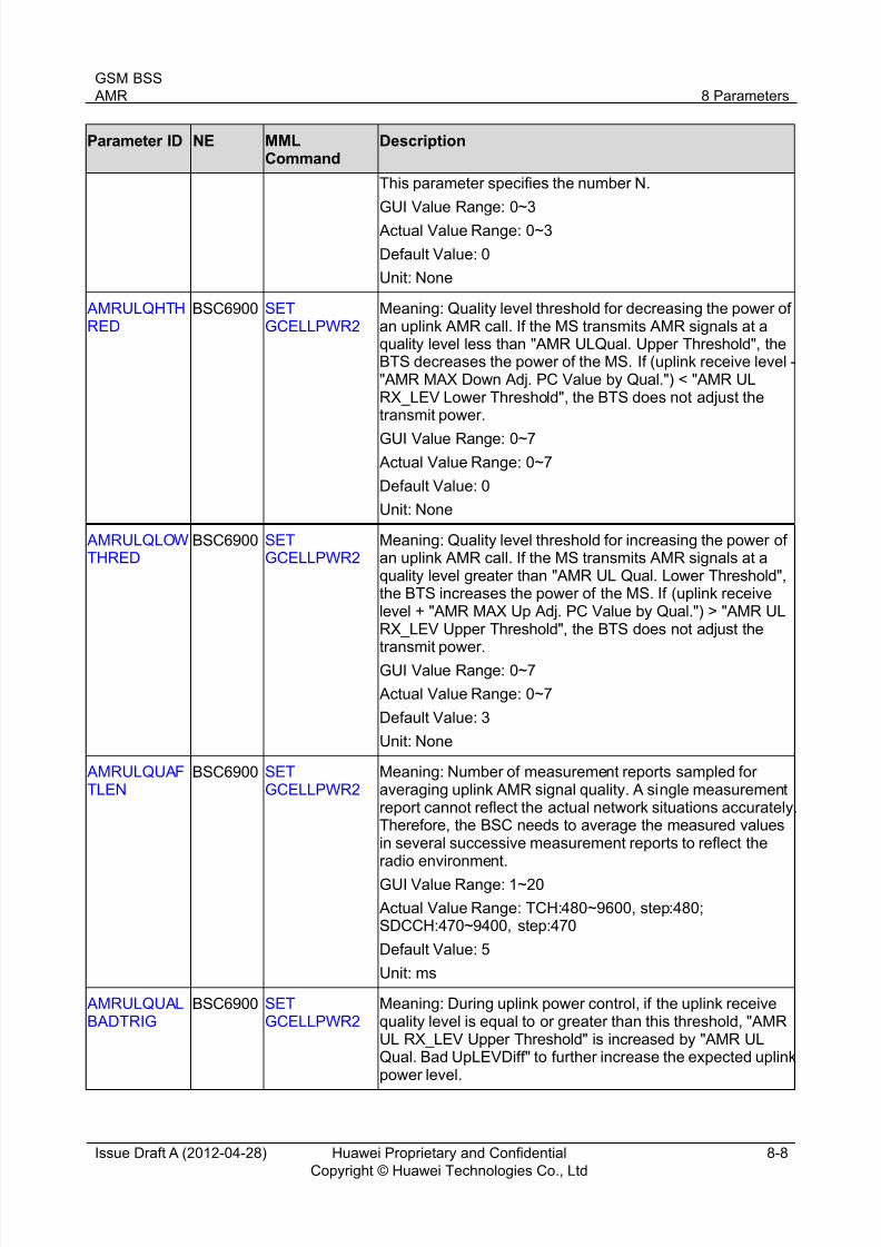
AMRULQHTHRED
AMRULQLOWTHRED
AMRDLSSHTHRED
AMRDLSSLTHRED
AMRDLQHTHRED
AMRDLQLTHRED
AMRMAXSTEP0
AMRMAXSTEP1
AMRMAXSTEP2
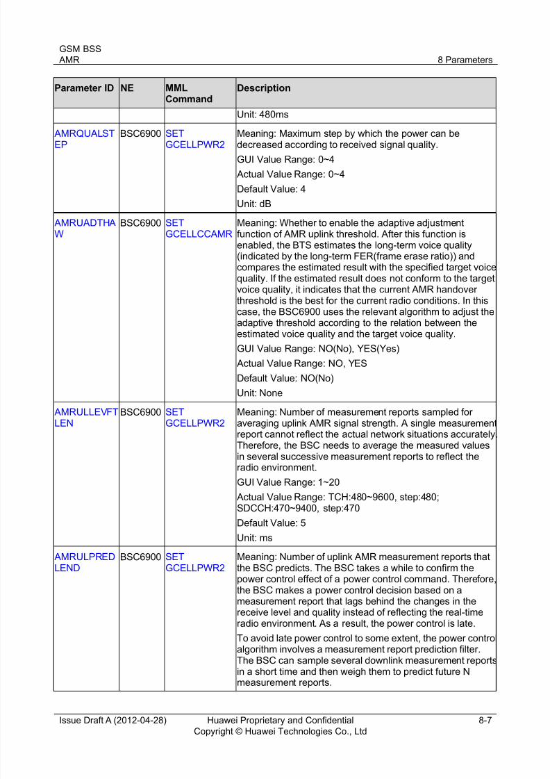
AMRQUALSTEP
AMRMAXVALADJRX
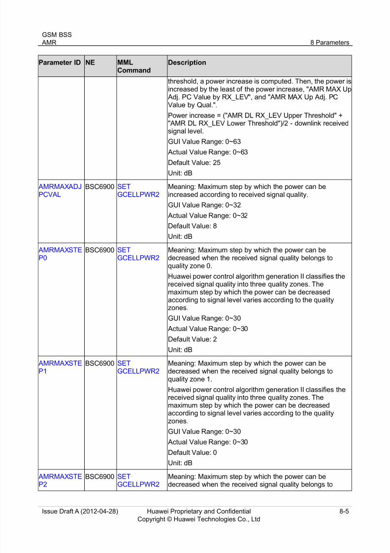
AMRMAXADJPCVAL
AMRULQUALBADTRIG
AMRULQUALBADUPLEV
AMRDLQUALBADTRIG
AMRDLQUALBADUPLEV
AMRBTSPWRNUM
3.6 AMR FR/HR Dynamic Adjustment
The AMR FR/HR Dynamic Adjustment feature is introduced in both handover algorithm I and handoveralgorithm II. For details, see the Handover Feature Parameter Description
This feature optimally balances the speech quality and the system capacity.
Before implementing the intra-cell AMR FR/HR Dynamic Adjustment, you must enable the half-rate service and AMR HR.
3.7 E-CODER
Enhanced Coding (E-CODER) optimizes AMR coding modules, therefore improving AMR voice quality.The emulation results show that E-CODER improves the MOS by 0.05 to 0.12. E-CODER is notsupported when A over IP and TFO are enabled. E-CODER is supported only in downlink.
To enable the E-CODER function, set EncodeMode to ECODEC(Enhanced code mode).
3.8 AMR Radio Link Timer AMR calls have stronger robustness than common calls. Therefore, AMR calls maintain good voicequality at a low rate even if common calls drop due to poor radio link quality. Setting the radio link timerfor AMR calls to the same value as that for common calls will cause unexpected AMR call drops. Thisdeteriorates user experience.
The Huawei BSC allows users to set radio link timers for AMR calls and common calls separately. Theradio link timers for AMR calls are classified into AMR FR and AMR HR radio link timers. Setting theradio link timer for AMR calls longer than that for common calls ensures that AMR calls are maintainedfor a long time in a poor radio environment. This reduces the call drop rate.
The AMR FR radio link timer is determined by the AFRDSBLCNT and AFRSAMULFRM parameters.
The AMR HR radio link timer is determined by the AHRDSBLCNT and AHRSAMULFRM parameters.

8/12/2019 AMR(GBSS14.0_01)
http://slidepdf.com/reader/full/amrgbss14001 14/41
GSM BSS
AMR 4 Related Features
Issue Draft A (2012-04-28) Huawei Proprietary and Confidential
Copyright © Huawei Technologies Co., Ltd
4-1
4 Related Features
Table 4-1 Related features
Feature Prerequisite Feature Mutually ExclusiveFeature Affected Feature
AMR FR None None None
AMR HR GBFD-113401 Half RateSpeech
None None
AMR Power Control GBFD-115501 AMR FR
GBFD-115502 AMR HR
None None
AMR Coding RateThreshold Adaptive Adjustment
GBFD-117501Enhanced MeasurementReport (EMR)
GBFD-115501 AMR FR
GBFD-115502 AMR HR
GBFD-115701 TFO
GBFD-117702 BTS Local
SwitchGBFD-117701 BSC LocalSwitch
GBFD-118602 A over IP
GBFD-118622 A IP overE1/T1
None
Um Interface SpeechFrame Repairing
None None None
AMR Radio Link Timer GBFD-115501 AMR FR
GBFD-115502 AMR HR
None None
AMR FR/HR Dynamic Adjustment
GBFD-115501 AMR FR
GBFD-115502 AMR HR
GBFD-110601 HUAWEII Handover
GBFD-510501 HUAWEIII Handover
None None

8/12/2019 AMR(GBSS14.0_01)
http://slidepdf.com/reader/full/amrgbss14001 15/41
GSM BSS
AMR 5 Impact on the Network
Issue Draft A (2012-04-28) Huawei Proprietary and Confidential
Copyright © Huawei Technologies Co., Ltd
5-1
5 Impact on the Network
5.1 AMR FR
5.1.1 Impact on System Capacity
The AMR FR feature provides a strong anti-interference capability to calls. This allows tight frequencyreuse and increases system capacity.
With this feature, calls in some weak coverage areas can be maintained. This reduces the possibility ofactive hang-ups, increasing the traffic volume.
5.1.2 Impact on Network Performance
The voice quality of 12.2 kbit/s AMR FR calls is equivalent to that of EFR calls and is better than that ofFR calls. In areas with weak signals, the voice quality of low-rate AMR FR calls is much better than that
of EFR and FR calls because of strong robustness of AMR FR calls.
5.2 AMR HR
5.2.1 Impact on System Capacity
When network capacity is limited, the AMR HR feature increases system capacity and reduces thenetwork congestion rate while maintaining acceptable voice quality.
5.2.2 Impact on Network Performance
The voice quality of 7.4 kbit/s AMR HR calls is better than that of HR calls. In weak coverage areas, thevoice quality of low-rate AMR HR calls is much better than that of HR calls because of strong robustness
of AMR HR calls.
5.3 AMR Power Control
5.3.1 Impact on System Capacity
The AMR Power Control feature improves the anti-interference capability. This allows tight frequencyreuse and increases system capacity.
5.3.2 Impact on Network Performance
AMR optimizes the speech codec but not the signaling codec. Therefore, AMR slightly affects the
handover success rate theoretically. AMR can expand the radio network coverage. Therefore, MSs canmake calls even if they are located in weak coverage areas. However, the receive quality inmeasurement reports (MRs) is poor, leading to bad quality handovers. When AMR is enabled, thenumber of bad quality handovers may increase. When the AMR Power Control feature is enabled,network interference decreases, and the number of handovers due to interference decreases.
This feature enhances the anti-interference capability for AMR calls, improving voice quality experienceof subscribers in weak coverage areas.
5.4 AMR Coding Rate Threshold Adaptive Adjustment
5.4.1 Impact on System Capacity
None

8/12/2019 AMR(GBSS14.0_01)
http://slidepdf.com/reader/full/amrgbss14001 16/41
GSM BSS
AMR 5 Impact on the Network
Issue Draft A (2012-04-28) Huawei Proprietary and Confidential
Copyright © Huawei Technologies Co., Ltd
5-2
5.4.2 Impact on Network Performance
The AMR Coding Rate Threshold Adaptive Adjustment feature makes AMR coding rate adjustmentthresholds and hysteresis more adaptive to the Um interface quality, improving the voice quality.
5.5 Um Interface Speech Frame Repairing
5.5.1 Impact on System Capacity
None
5.5.2 Impact on Network Performance
In weak coverage areas with low a CIR, the Um Interface Speech Frame Repairing feature reduces theproportion of frame loss due to poor signal quality, improving the voice quality.
5.6 AMR Radio Link Timer
5.6.1 Impact on System Capacity
None
5.6.2 Impact on Network Performance
AMR FR improves the robustness of AMR FR speech frames but not the robustness of SACCH signalingframes. Therefore, AMR FR does not affect the TCH call drop rate theoretically. In practice, however,when AMR FR is enabled, the TCH call drop rate increases because of the following causes:
For EFR/FR/HR calls, SACCH signaling frames have the similar robustness to that of speech frames.Therefore, a subscriber in a weak coverage area may hang up the phone because of poorconversation quality. Such a hang-up is not counted as a call drop. However, such a hang-up for an AMR call is counted as a call drop.
When AMR FR is enabled, the robustness of AMR FR speech frames is stronger than that of SACCHsignaling frames. Therefore, speech frames area can be correctly decoded in a weak coverage, andtherefore subscribers will not hang up the phone. SACCH frames, however, cannot be correctlydecoded. Therefore, RLT expires, and call drops occur, leading to an increase in the TCH call droprate.
AMR FR and AMR HR incorporates the following parameters: AFRDSBLCNT , AHRDSBLCNT , AFRSAMULFRM , and AHRSAMULFRM . By modifying the settings of these parameters, you canimprove the robustness of SACCH signaling frames and enhance network coverage performance using AMR to decrease the TCH call drop rate.
5.7 AMR FR/HR Dynamic Adjustment
5.7.1 Impact on System Capacity
Conversion from AMR FR to AMR HR increases network capacity and decreases network deploymentcosts while maintaining voice quality.
5.7.2 Impact on Network Performance
Conversion from AMR HR to AMR FR improves the Um interface quality when the radio link qualitydeteriorates. This improves network performance.

8/12/2019 AMR(GBSS14.0_01)
http://slidepdf.com/reader/full/amrgbss14001 17/41
GSM BSS
AMR 6 Engineering Guidelines
Issue Draft A (2012-04-28) Huawei Proprietary and Confidential
Copyright © Huawei Technologies Co., Ltd
6-1
6 Engineering Guidelines
6.1 When to Use AMR
6.1.1 AMR FR and AMR HR
It is recommended that the AMR FR or AMR HR feature be used in the following scenarios:
Capacity-sufficient scenarios: If the number of AMR calls reach a certain proportion, enable AMR FRor AMR HR in some cells to improve voice quality and user experience.
Capacity-limited scenarios: Based on the strong anti-interference capability of AMR, tight frequencyreuse can be used. Based on the similarity of voice quality between AMR FR used with AMR HR and AMR FR, some HR channels can be used to improve the network capacity while maintaining networkquality.
6.1.2 AMR Power Control
It is recommended that the AMR Power Control feature be used with AMR FR or AMR HR. Thisenhances anti-interference capability, increases network capacity, and improves voice quality.
6.1.3 AMR Coding Rate Threshold Adaptive Adjustment
It is recommended that the AMR Coding Rate Threshold Adaptive Adjustment feature be used whenradio link quality varies frequently or network planning personnel are difficult to predict radio quality. Withthis feature, the BTS adaptively adjusts AMR coding rate thresholds to ensure AMR performance.
6.1.4 Um Interface Speech Frame Repairing
It is recommended that the Um Interface Speech Frame Repairing feature be used when poor uplinkreceive quality causes a high uplink Frame Erase Ratio (FER). This feature repairs speech frames,improving uplink voice quality.
6.1.5 AMR Radio Link Timer
It is recommended that the AMR Radio Link Timer feature be used with AMR FR or AMR HR. Thisdecreases the call drop rate and improves user experience.
6.1.6 AMR FR/HR Dynamic Adjustment
It is recommended that the AMR FR/HR Dynamic Adjustment feature be used in a capacity-limitedscenario where both AMR FR and AMR HR are used. This helps balance cell capacity and voice quality.
6.2 Information to Be Collected
6.2.1 AMR FR and AMR HR
Before deploying the AMR FR or AMR HR feature, collect the following information: AMR-capable MSpenetration rate and Um-interface coverage quality. For AMR HR deployment, you also need to learnabout the network load. If the network is congested, you are advised to enable AMR HR.
6.2.2 AMR Power Control
None

8/12/2019 AMR(GBSS14.0_01)
http://slidepdf.com/reader/full/amrgbss14001 18/41
GSM BSS
AMR 6 Engineering Guidelines
Issue Draft A (2012-04-28) Huawei Proprietary and Confidential
Copyright © Huawei Technologies Co., Ltd
6-2
6.2.3 AMR Coding Rate Threshold Adaptive Adjustment
Before deploying the AMR Coding Rate Threshold Adaptive Adjustment feature, analyze networkinterference and determine AMR coding rate adjustment thresholds. This feature supports the functionsof uplink and downlink AMR coding rate threshold adaptive adjustment. The downlink AMR coding ratethreshold adaptive adjustment function depends on the Enhanced Measurement Report (EMR) feature.Before enabling this function, collect the EMR-capable MS penetration rate.
6.2.4 Um Interface Speech Frame Repairing
Before deploying the Um Interface Speech Frame Repairing feature, check whether there are a largenumber of calls with poor uplink quality.
6.2.5 AMR Radio Link Timer
Before deploying the AMR Radio Link Timer feature, collect the AMR FR or AMR HR call drop rate.
6.2.6 AMR FR/HR Dynamic AdjustmentBefore deploying the AMR FR/HR Dynamic Adjustment feature, check whether the network is congestedand whether AMR HR is enabled.
6.3 Network Planning
6.3.1 AMR FR and AMR HR
RF Planning
According to the impact of AMR on network capacity and quality, RF planning for AMR is as follows:Compared with FR and EFR, AMR supports a lower CIR with the same voice quality. In addition, AMRimproves network performance in a tight frequency reuse pattern. Therefore, you can configure somechannels on a TRX as AMR HR channels with the same network frequency planning so that these AMRHR channels are allocated to AMR calls. This increases system capacity.
Certain MSs do not support AMR. Therefore, you must appropriately plan the network capacity based onthe AMR-capable MS penetration rate and select a proper frequency reuse pattern for frequencyplanning. If you perform network planning without considering the MSs that do not support AMR, theoverall network KPIs deteriorate.
Network Topology
N/A
Hardware Planning
N/A
6.3.2 AMR Power Control
N/A
6.3.3 AMR Coding Rate Threshold Adaptive Adjustment
N/A

8/12/2019 AMR(GBSS14.0_01)
http://slidepdf.com/reader/full/amrgbss14001 19/41
GSM BSS
AMR 6 Engineering Guidelines
Issue Draft A (2012-04-28) Huawei Proprietary and Confidential
Copyright © Huawei Technologies Co., Ltd
6-3
6.3.4 Um Interface Speech Frame Repairing
N/A
6.3.5 AMR Radio Link TimerN/A
6.3.6 AMR FR/HR Dynamic Adjustment
N/A
6.4 Deploying AMR FR and AMR HR
For details about how to activate, verify, and deactivate this feature, see Configuring AMR .
6.5 Deploying AMR Power Control
For details about how to activate, verify, and deactivate this feature, see Configuring AMR .
6.6 Deploying AMR Coding Rate Threshold AdaptiveAdjustment
For details about how to activate, verify, and deactivate this feature, see Configuring AMR Coding RateThreshold Adaptive Adjustment .
6.7 Deploying Um Interface Speech Frame Repairing
For details about how to activate, verify, and deactivate this feature, see Configuring Um InterfaceSpeech Frame Repairing .
6.8 Deploying AMR Radio Link Timer
For details about how to activate, verify, and deactivate this feature, see Configuring AMR .
6.9 Deploying AMR FR/HR Dynamic Adjustment
For details about how to activate, verify, and deactivate this feature, see Configuring HUAWEI IIHandover .
8/12/2019 AMR(GBSS14.0_01)
http://slidepdf.com/reader/full/amrgbss14001 20/41
GSM BSS
AMR 7 Performance Optimization
Issue Draft A (2012-04-28) Huawei Proprietary and Confidential
Copyright © Huawei Technologies Co., Ltd
7-1
7 Performance Optimization
7.1 AMR FR and AMR HR
Monitoring
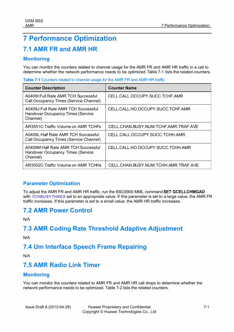
You can monitor the counters related to channel usage for the AMR FR and AMR HR traffic in a cell todetermine whether the network performance needs to be optimized. Table 7-1 lists the related counters.
Table 7-1 Counters related to channel usage for the AMR FR and AMR HR traffic
Counter Description Counter Name
A0409I:Full Rate AMR TCH SuccessfulCall Occupancy Times (Service Channel)
CELL.CALL.OCCUPY.SUCC.TCHF.AMR
A0409J:Full Rate AMR TCH SuccessfulHandover Occupancy Times (ServiceChannel)
CELL.CALL.HO.OCCUPY.SUCC.TCHF.AMR
AR3551C:Traffic Volume on AMR TCHFs CELL.CHAN.BUSY.NUM.TCHF.AMR.TRAF.AVE
A0409L:Half Rate AMR TCH SuccessfulCall Occupancy Times (Service Channel)
CELL.CALL.OCCUPY.SUCC.TCHH.AMR
A0409M:Half Rate AMR TCH SuccessfulHandover Occupancy Times (ServiceChannel)
CELL.CALL.HO.OCCUPY.SUCC.TCHH.AMR
AR3552C:Traffic Volume on AMR TCHHs CELL.CHAN.BUSY.NUM.TCHH.AMR.TRAF.AVE
Parameter Optimization
To adjust the AMR FR and AMR HR traffic, run the BSC6900 MML command SET GCELLCHMGAD with TCHBUSYTHRES set to an appropriate value. If this parameter is set to a large value, the AMR FRtraffic increases. If this parameter is set to a small value, the AMR HR traffic increases.
7.2 AMR Power Control
N/A
7.3 AMR Coding Rate Threshold Adaptive Adjustment
N/A
7.4 Um Interface Speech Frame Repairing
N/A
7.5 AMR Radio Link Timer
Monitoring
You can monitor the counters related to AMR FR and AMR HR call drops to determine whether thenetwork performance needs to be optimized. Table 7-2 lists the related counters.

8/12/2019 AMR(GBSS14.0_01)
http://slidepdf.com/reader/full/amrgbss14001 21/41
GSM BSS
AMR 7 Performance Optimization
Issue Draft A (2012-04-28) Huawei Proprietary and Confidential
Copyright © Huawei Technologies Co., Ltd
7-2
Table 7-2 Counters related to AMR FR and AMR HR call drops
Counter Description Counter Name
M0121A:Full Rate AMR Service Channel
Call Drop Times
CELL.CALL.DROP.AMRFR.CAll.FAIL
M0121B:Half Rate AMR Service ChannelCall Drop Times
CELL.CALL.DROP.AMRHR.CAll.FAIL
A0409N:Full Rate AMR Call Drop Rate CELL.CALL.DROP.CALL.RATE.TCHF.AMR
A0409P:Half Rate AMR Call Drop Rate CELL.CALL.DROP.CALL.RATE.TCHH.AMR
Parameter Optimization
To adjust the effect of the AMR Radio Link Timer feature, run the BSC6900 MML command SET
GCELLCCBASIC with AFRSAMULFRM , AHRSAMULFRM , AFRDSBLCNT , and AHRDSBLCNT set toappropriate values. The larger the value of this parameter, the lower the call drop rate, but the morechannel resources are wasted. The smaller the value of this parameter, the fewer channel resources arewasted, but the higher the call drop rate.
7.6 AMR FR/HR Dynamic Adjustment
See the Handover Feature Parameter Description.

8/12/2019 AMR(GBSS14.0_01)
http://slidepdf.com/reader/full/amrgbss14001 22/41
GSM BSS
AMR 8 Parameters
Issue Draft A (2012-04-28) Huawei Proprietary and Confidential
Copyright © Huawei Technologies Co., Ltd
8-1
8 Parameters
Table 8-1 Parameter description
Parameter ID NE MMLCommand Description
ACTCDSETF BSC6900 SETGCELLCCAMR
Meaning: Active coding set (ACS)[F], indicates a set offull-rate coding rates currently available for calls. The AMR isa set of multiple speech coding and decoding rates.If an IPbased user plane A-Interface is chosen,5.15KBIT/S will notbe included(see 3GPP TS 28.062).
GUI Value Range: 4_75KBIT/S, 5_15KBIT/S, 5_90KBIT/S,6_70KBIT/S, 7_40KBIT/S, 7_95KBIT/S, 10_2KBIT/S,12_2KBIT/S
Actual Value Range: 4_75KBIT/S, 5_15KBIT/S, 5_90KBIT/S,
6_70KBIT/S, 7_40KBIT/S, 7_95KBIT/S, 10_2KBIT/S,12_2KBIT/S
Default Value:4_75KBIT/S-1&5_15KBIT/S-0&5_90KBIT/S-1&6_70KBIT/S-0&7_40KBIT/S-1&7_95KBIT/S-0&10_2KBIT/S-0&12_2KBIT/S-1
Unit: None
AFRDSBLCNT BSC6900 SETGCELLCCBASIC
Meaning: Counter for radio link failures during an AMR fullr ate call. See the description of "Radio Link Timeout" in "SETGCELLCCBASIC".
GUI Value Range: 4_Times, 8_Times, 12_Times, 16_Times,
20_Times, 24_Times, 28_Times, 32_Times, 36_Times,40_Times, 44_Times, 48_Times, 52_Times, 56_Times,60_Times, 64_Times
Actual Value Range: 1920~30720
Default Value: 64_Times
Unit: 480ms
AFRSAMULFRM
BSC6900 SETGCELLCCBASIC
Meaning: Number of SACCH multiframes during an AMR fullr ate call. See the description of "SACCH Multi-Frames" in"SET GCELLCCBASIC".
GUI Value Range: 0~63
Actual Value Range: 0~30240
Default Value: 48
Unit: 480ms
AHRDSBLCNT
BSC6900 SETGCELLCCBASIC
Meaning: Counter for radio link failures during an AMR halfr ate call. See the description of "Radio Link Timeout" in "SETGCELLCCBASIC".
GUI Value Range: 4_Times, 8_Times, 12_Times, 16_Times,20_Times, 24_Times, 28_Times, 32_Times, 36_Times,40_Times, 44_Times, 48_Times, 52_Times, 56_Times,60_Times, 64_Times
Actual Value Range: 1920~30720

8/12/2019 AMR(GBSS14.0_01)
http://slidepdf.com/reader/full/amrgbss14001 23/41
GSM BSS
AMR 8 Parameters
Issue Draft A (2012-04-28) Huawei Proprietary and Confidential
Copyright © Huawei Technologies Co., Ltd
8-2
Parameter ID NE MMLCommand
Description
Default Value: 52_Times
Unit: 480ms
AHRSAMULFRM
BSC6900 SETGCELLCCBASIC
Meaning: Number of SACCH multiframes during an AMRhalf rate call. See the description of "SACCH Multi-Frames"in "SET GCELLCCBASIC".
GUI Value Range: 0~63
Actual Value Range: 0~30240
Default Value: 32
Unit: 480ms
AMRBTSPWRNUM
BSC6900 SETGCELLPWR2
Meaning: Maximum degree by which the BSC can control thepower of the AMR BTS dynamically
GUI Value Range: 1~16
Actual Value Range: 2~32
Default Value: 16
Unit: 2dB
AMRDADTHAW
BSC6900 SETGCELLCCAMR
Meaning: Whether to enable the adaptive adjustmentfunction of AMR downlink threshold. After this function isenabled, the BTS estimates the long-term voice quality(indicated by the long-term FER(frame erase ratio)) andcompares the estimated result with the specified target voicequality. If the estimated result does not conform to the target
voice quality, it indicates that the current AMR handoverthreshold is not the best for the current radio conditions. Inthis case, the BSC6900 adjusts threshold adaptivelyaccording to the relationship between the estimated voicequality and the target voice quality.
GUI Value Range: NO(No), YES(Yes)
Actual Value Range: NO, YES
Default Value: NO(No)
Unit: None
AMRDLLEVFTLEN
BSC6900 SETGCELLPWR2
Meaning: Number of measurement reports sampled foraveraging downlink AMR signal strength. A single
measurement report cannot reflect the actual networksituations accurately. Therefore, the BSC needs to averagethe measured values in several successive measurementreports to reflect the radio environment.
GUI Value Range: 1~20
Actual Value Range: TCH:480~9600, step:480;SDCCH:470~9400, step:470
Default Value: 5
Unit: ms
AMRDLPRED
LEND
BSC6900 SET
GCELLPWR2
Meaning: Number of downlink AMR measurement reports
that the BSC predicts. The BSC takes a while to confirm the

8/12/2019 AMR(GBSS14.0_01)
http://slidepdf.com/reader/full/amrgbss14001 24/41
GSM BSS
AMR 8 Parameters
Issue Draft A (2012-04-28) Huawei Proprietary and Confidential
Copyright © Huawei Technologies Co., Ltd
8-3
Parameter ID NE MMLCommand
Description
power control effect of a power control command. Thus, theBSC makes a power control decision based on a
measurement report that lags behind the changes in thereceive level and quality instead of reflecting the real-timeradio environment. As a result, the power control is late.
To prevent late power control to a specified degree, thepower control algorithm involves a measurement reportprediction filter. The BSC can sample several downlinkmeasurement reports in a short time and filter themaccording to a specific weight to predict future Nmeasurement reports.
This parameter specifies the number N.
GUI Value Range: 0~3
Actual Value Range: 0~3Default Value: 0
Unit: None
AMRDLQHTHRED
BSC6900 SETGCELLPWR2
Meaning: Quality level threshold for decreasing downlink AMR signal power. If the BTS transmits AMR signals at aquality level less than "AMR DL Qual. Upper Threshold", theBSC decreases the power of the BTS. If (downlink receivelevel - "AMR MAX Down Adj. PC Value by Qual.") < "AMRDL RX_LEV Lower Threshold", the BSC does not adjust thetransmit power.
GUI Value Range: 0~7
Actual Value Range: 0~7
Default Value: 0
Unit: None
AMRDLQLTHRED
BSC6900 SETGCELLPWR2
Meaning: Quality level threshold for increasing downlink AMR signal power. If the BTS transmits AMR signals at aquality level greater than "AMR DL Qual. Lower Threshold",the BSC increases the power of the BTS. If (downlink receivelevel + "AMR MAX Up Adj. PC Value by Qual.") > "AMR DLRX_LEV Upper Threshold", the BSC does not adjust thetransmit power.
GUI Value Range: 0~7
Actual Value Range: 0~7
Default Value: 3
Unit: None
AMRDLQUAFTLEN
BSC6900 SETGCELLPWR2
Meaning: Number of measurement reports sampled foraveraging downlink AMR signal quality. A singlemeasurement report cannot reflect the actual networksituations accurately. Therefore, the BSC needs to averagethe measured values in several successive measurementreports to reflect the radio environment.
GUI Value Range: 1~20
8/12/2019 AMR(GBSS14.0_01)
http://slidepdf.com/reader/full/amrgbss14001 25/41
GSM BSS
AMR 8 Parameters
Issue Draft A (2012-04-28) Huawei Proprietary and Confidential
Copyright © Huawei Technologies Co., Ltd
8-4
Parameter ID NE MMLCommand
Description
Actual Value Range: TCH:480~9600, step:480;SDCCH:470~9400, step:470
Default Value: 5
Unit: ms
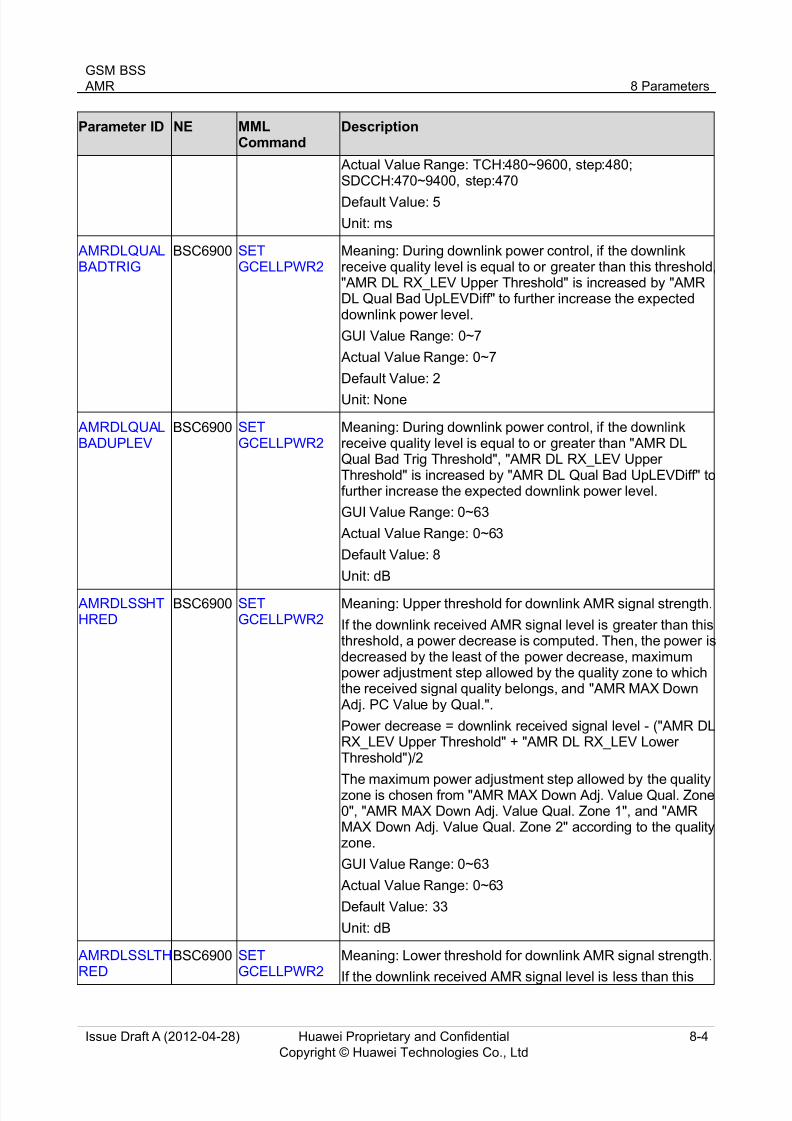
AMRDLQUALBADTRIG
BSC6900 SETGCELLPWR2
Meaning: During downlink power control, if the downlinkreceive quality level is equal to or greater than this threshold,"AMR DL RX_LEV Upper Threshold" is increased by "AMRDL Qual Bad UpLEVDiff" to further increase the expecteddownlink power level.
GUI Value Range: 0~7
Actual Value Range: 0~7
Default Value: 2
Unit: None
AMRDLQUALBADUPLEV
BSC6900 SETGCELLPWR2
Meaning: During downlink power control, if the downlinkreceive quality level is equal to or greater than "AMR DLQual Bad Trig Threshold", "AMR DL RX_LEV UpperThreshold" is increased by "AMR DL Qual Bad UpLEVDiff" tofurther increase the expected downlink power level.
GUI Value Range: 0~63
Actual Value Range: 0~63
Default Value: 8
Unit: dB
AMRDLSSHTHRED
BSC6900 SETGCELLPWR2
Meaning: Upper threshold for downlink AMR signal strength.
If the downlink received AMR signal level is greater than thisthreshold, a power decrease is computed. Then, the power isdecreased by the least of the power decrease, maximumpower adjustment step allowed by the quality zone to whichthe received signal quality belongs, and "AMR MAX Down Adj. PC Value by Qual.".
Power decrease = downlink received signal level - ("AMR DLRX_LEV Upper Threshold" + "AMR DL RX_LEV LowerThreshold")/2
The maximum power adjustment step allowed by the qualityzone is chosen from "AMR MAX Down Adj. Value Qual. Zone0", "AMR MAX Down Adj. Value Qual. Zone 1", and "AMRMAX Down Adj. Value Qual. Zone 2" according to the qualityzone.
GUI Value Range: 0~63
Actual Value Range: 0~63
Default Value: 33
Unit: dB
AMRDLSSLTHRED
BSC6900 SETGCELLPWR2
Meaning: Lower threshold for downlink AMR signal strength.
If the downlink received AMR signal level is less than this
8/12/2019 AMR(GBSS14.0_01)
http://slidepdf.com/reader/full/amrgbss14001 26/41
GSM BSS
AMR 8 Parameters
Issue Draft A (2012-04-28) Huawei Proprietary and Confidential
Copyright © Huawei Technologies Co., Ltd
8-5
Parameter ID NE MMLCommand
Description
threshold, a power increase is computed. Then, the power isincreased by the least of the power increase, "AMR MAX Up
Adj. PC Value by RX_LEV", and "AMR MAX Up Adj. PCValue by Qual.".
Power increase = ("AMR DL RX_LEV Upper Threshold" +"AMR DL RX_LEV Lower Threshold")/2 - downlink receivedsignal level.
GUI Value Range: 0~63
Actual Value Range: 0~63
Default Value: 25
Unit: dB
AMRMAXADJ
PCVAL
BSC6900 SET
GCELLPWR2
Meaning: Maximum step by which the power can be
increased according to received signal quality.
GUI Value Range: 0~32
Actual Value Range: 0~32
Default Value: 8
Unit: dB
AMRMAXSTEP0
BSC6900 SETGCELLPWR2
Meaning: Maximum step by which the power can bedecreased when the received signal quality belongs toquality zone 0.
Huawei power control algorithm generation II classifies thereceived signal quality into three quality zones. The
maximum step by which the power can be decreasedaccording to signal level varies according to the qualityzones.
GUI Value Range: 0~30
Actual Value Range: 0~30
Default Value: 2
Unit: dB
AMRMAXSTEP1
BSC6900 SETGCELLPWR2
Meaning: Maximum step by which the power can bedecreased when the received signal quality belongs toquality zone 1.
Huawei power control algorithm generation II classifies thereceived signal quality into three quality zones. Themaximum step by which the power can be decreasedaccording to signal level varies according to the qualityzones.
GUI Value Range: 0~30
Actual Value Range: 0~30
Default Value: 0
Unit: dB
AMRMAXSTE
P2
BSC6900 SET
GCELLPWR2
Meaning: Maximum step by which the power can be
decreased when the received signal quality belongs to

8/12/2019 AMR(GBSS14.0_01)
http://slidepdf.com/reader/full/amrgbss14001 27/41
GSM BSS
AMR 8 Parameters
Issue Draft A (2012-04-28) Huawei Proprietary and Confidential
Copyright © Huawei Technologies Co., Ltd
8-6
Parameter ID NE MMLCommand
Description
quality zone 2.
Huawei power control algorithm generation II classifies thereceived signal quality into three quality zones. Themaximum step by which the power can be decreasedaccording to signal level varies according to the qualityzones.
GUI Value Range: 0~30
Actual Value Range: 0~30
Default Value: 0
Unit: dB
AMRMAXVAL ADJRX
BSC6900 SETGCELLPWR2
Meaning: Maximum step by which the power can beincreased according to received signal level.
GUI Value Range: 0~32
Actual Value Range: 0~32
Default Value: 8
Unit: dB
AMRMRCOMPREG
BSC6900 SETGCELLPWR2
Meaning: Whether to enable the compensation of AMRmeasurement reports in Huawei power control algorithm II.
If this parameter is set to YES, Huawei power controlalgorithm II puts a currently received measurement reportinto the measurement report compensation queue. Then, thealgorithm records the change in the transmit power based on
the MS/BTS power in the measurement report. According tothe power change, the algorithm compensates the receivedsignal level in a history measurement report aftermeasurement report interpolation.
Before making a power control decision, the BSC samplesand weights the received signal level and quality in severalhistory measurement reports. The MS/BTS transmit powervaries over these measurement reports. To ensure theaccuracy of the received signal level and quality to beweighted, the power control algorithm needs to compensatethe received signal level and quality in the historymeasurement reports where the transmit power differs from
the current transmit power.
GUI Value Range: NO(No), YES(Yes)
Actual Value Range: NO, YES
Default Value: YES(Yes)
Unit: None
AMRPCADJPERIOD
BSC6900 SETGCELLPWR2
Meaning: Minimum interval between two consecutive AMRpower control commands.
GUI Value Range: 1~15
Actual Value Range: 480~7200
Default Value: 3
8/12/2019 AMR(GBSS14.0_01)
http://slidepdf.com/reader/full/amrgbss14001 28/41
GSM BSS
AMR 8 Parameters
Issue Draft A (2012-04-28) Huawei Proprietary and Confidential
Copyright © Huawei Technologies Co., Ltd
8-7
Parameter ID NE MMLCommand
Description
Unit: 480ms
AMRQUALSTEP BSC6900 SETGCELLPWR2 Meaning: Maximum step by which the power can bedecreased according to received signal quality.
GUI Value Range: 0~4
Actual Value Range: 0~4
Default Value: 4
Unit: dB
AMRUADTHAW
BSC6900 SETGCELLCCAMR
Meaning: Whether to enable the adaptive adjustmentfunction of AMR uplink threshold. After this function isenabled, the BTS estimates the long-term voice quality(indicated by the long-term FER(frame erase ratio)) andcompares the estimated result with the specified target voicequality. If the estimated result does not conform to the targetvoice quality, it indicates that the current AMR handoverthreshold is the best for the current radio conditions. In thiscase, the BSC6900 uses the relevant algorithm to adjust theadaptive threshold according to the relation between theestimated voice quality and the target voice quality.
GUI Value Range: NO(No), YES(Yes)
Actual Value Range: NO, YES
Default Value: NO(No)
Unit: None
AMRULLEVFTLEN
BSC6900 SETGCELLPWR2
Meaning: Number of measurement reports sampled foraveraging uplink AMR signal strength. A single measurementreport cannot reflect the actual network situations accurately.Therefore, the BSC needs to average the measured valuesin several successive measurement reports to reflect theradio environment.
GUI Value Range: 1~20
Actual Value Range: TCH:480~9600, step:480;SDCCH:470~9400, step:470
Default Value: 5
Unit: ms
AMRULPREDLEND
BSC6900 SETGCELLPWR2
Meaning: Number of uplink AMR measurement reports thatthe BSC predicts. The BSC takes a while to confirm thepower control effect of a power control command. Therefore,the BSC makes a power control decision based on ameasurement report that lags behind the changes in thereceive level and quality instead of reflecting the real-timeradio environment. As a result, the power control is late.
To avoid late power control to some extent, the power controlalgorithm involves a measurement report prediction filter.The BSC can sample several downlink measurement reportsin a short time and then weigh them to predict future N
measurement reports.
8/12/2019 AMR(GBSS14.0_01)
http://slidepdf.com/reader/full/amrgbss14001 29/41
GSM BSS
AMR 8 Parameters
Issue Draft A (2012-04-28) Huawei Proprietary and Confidential
Copyright © Huawei Technologies Co., Ltd
8-8
Parameter ID NE MMLCommand
Description
This parameter specifies the number N.
GUI Value Range: 0~3
Actual Value Range: 0~3
Default Value: 0
Unit: None
AMRULQHTHRED
BSC6900 SETGCELLPWR2
Meaning: Quality level threshold for decreasing the power ofan uplink AMR call. If the MS transmits AMR signals at aquality level less than "AMR ULQual. Upper Threshold", theBTS decreases the power of the MS. If (uplink receive level -"AMR MAX Down Adj. PC Value by Qual.") < "AMR ULRX_LEV Lower Threshold", the BTS does not adjust thetransmit power.
GUI Value Range: 0~7
Actual Value Range: 0~7
Default Value: 0
Unit: None
AMRULQLOWTHRED
BSC6900 SETGCELLPWR2
Meaning: Quality level threshold for increasing the power ofan uplink AMR call. If the MS transmits AMR signals at aquality level greater than "AMR UL Qual. Lower Threshold",the BTS increases the power of the MS. If (uplink receivelevel + "AMR MAX Up Adj. PC Value by Qual.") > "AMR ULRX_LEV Upper Threshold", the BTS does not adjust thetransmit power.
GUI Value Range: 0~7
Actual Value Range: 0~7
Default Value: 3
Unit: None
AMRULQUAFTLEN
BSC6900 SETGCELLPWR2
Meaning: Number of measurement reports sampled foraveraging uplink AMR signal quality. A single measurementreport cannot reflect the actual network situations accurately.Therefore, the BSC needs to average the measured valuesin several successive measurement reports to reflect theradio environment.
GUI Value Range: 1~20
Actual Value Range: TCH:480~9600, step:480;SDCCH:470~9400, step:470
Default Value: 5
Unit: ms
AMRULQUALBADTRIG
BSC6900 SETGCELLPWR2
Meaning: During uplink power control, if the uplink receivequality level is equal to or greater than this threshold, "AMRUL RX_LEV Upper Threshold" is increased by "AMR ULQual. Bad UpLEVDiff" to further increase the expected uplinkpower level.

8/12/2019 AMR(GBSS14.0_01)
http://slidepdf.com/reader/full/amrgbss14001 30/41
GSM BSS
AMR 8 Parameters
Issue Draft A (2012-04-28) Huawei Proprietary and Confidential
Copyright © Huawei Technologies Co., Ltd
8-9
Parameter ID NE MMLCommand
Description
GUI Value Range: 0~7
Actual Value Range: 0~7
Default Value: 3
Unit: None
AMRULQUALBADUPLEV
BSC6900 SETGCELLPWR2
Meaning: During uplink power control, if the uplink receivequality level is equal to or greater than "AMR UL Qual. BadTrig Threshold", "AMR UL RX_LEV Upper Threshold" isincreased by "AMR UL Qual. Bad UpLEVDiff" to furtherincrease the expected uplink power level.
GUI Value Range: 0~63
Actual Value Range: 0~63
Default Value: 6
Unit: dB
AMRULSSHTHRED
BSC6900 SETGCELLPWR2
Meaning: Upper threshold for uplink AMR signal strength
If the uplink received AMR signal level is greater than thisthreshold, a power decrease is computed. Then, the power isdecreased by the least of the power decrease, maximumpower adjustment step allowed by the quality zone to whichthe received signal quality belongs, and "AMR MAX Down Adj. PC Value by Qual.".
Power decrease = uplink received signal level - ("AMR ULRX_LEV Upper Threshold" + "AMR UL RX_LEV Lower
Threshold")/2The maximum power adjustment step allowed by the qualityzone is chosen from "AMR MAX Down Adj. Value Qual. Zone0", "AMR MAX Down Adj. Value Qual. Zone 1", and "AMRMAX Down Adj. Value Qual. Zone 2" according to the qualityzone.
GUI Value Range: 0~63
Actual Value Range: 0~63
Default Value: 30
Unit: dB
AMRULSSLTHRED
BSC6900 SETGCELLPWR2
Meaning: Lower threshold for uplink AMR signal strength.If the uplink received AMR signal level is less than thisthreshold, a power increase is computed. Then, the power isincreased by the least of the power increase, "AMR MAX Up Adj. PC Value by RX_LEV", and "AMR MAX Up Adj. PCValue by Qual.".
Power increase = ("AMR UL RX_LEV Upper Threshold" +"AMR UL RX_LEV Lower Threshold")/2 - uplink receivedsignal level.
GUI Value Range: 0~63
Actual Value Range: 0~63

8/12/2019 AMR(GBSS14.0_01)
http://slidepdf.com/reader/full/amrgbss14001 31/41
GSM BSS
AMR 8 Parameters
Issue Draft A (2012-04-28) Huawei Proprietary and Confidential
Copyright © Huawei Technologies Co., Ltd
8-10
Parameter ID NE MMLCommand
Description
Default Value: 18
Unit: dB
DLLTFERLOWTH
BSC6900 SETGCELLCCAMR
Meaning: Lower voice quality threshold associated with theautomatic adjustment of the AMR downlink handoverthreshold. The value of this parameter must be smaller thanor equal to the value of "Downlink Long-term FER Target".
GUI Value Range: 2~255
Actual Value Range: 2~255
Default Value: 2
Unit: None
DLLTFERTGT BSC6900 SET
GCELLCCAMR
Meaning: Target value of the voice quality automatically
adjusted through the downlink threshold of AMR handoverGUI Value Range: 2~255
Actual Value Range: 2~255
Default Value: 8
Unit: None
DLLTFERUPTH
BSC6900 SETGCELLCCAMR
Meaning: Upper voice quality threshold associated with theautomatic adjustment of the AMR handover downlinkthreshold.
GUI Value Range: 2~255
Actual Value Range: 2~255
Default Value: 60
Unit: None
DLLTTHADJF A
BSC6900 SETGCELLCCAMR
Meaning: Factor of downlink threshold adjustment. Itindicates the linear relation between the thresholdadjustment value and the logarithmic FER.
GUI Value Range: 2~255
Actual Value Range: 2~255
Default Value: 40
Unit: None
EncodeMode BSC6900 SET TCPARA Meaning: Whether to improve the voice quality of AMR andEFR services. If this switch is turned on, the downlink MOSof AMR and EFR services is significantly improved. Thisparameter is used in A over TDM.
GUI Value Range: STANDARD(Standard code mode),ECODEC(Enhanced code mode)
Actual Value Range: STANDARD, ECODEC
Default Value: STANDARD(Standard code mode)
Unit: None
LTFERLOWT
H
BSC6900 SET
GCELLCCAMR
Meaning: Lower voice quality threshold associated with the
automatic adjustment of the AMR handover uplink

8/12/2019 AMR(GBSS14.0_01)
http://slidepdf.com/reader/full/amrgbss14001 32/41
GSM BSS
AMR 8 Parameters
Issue Draft A (2012-04-28) Huawei Proprietary and Confidential
Copyright © Huawei Technologies Co., Ltd
8-11
Parameter ID NE MMLCommand
Description
threshold;The value of this parameter must be smaller thanor equal to the value of Uplink Long-term FER Target.
GUI Value Range: 2~255
Actual Value Range: 2~255
Default Value: 2
Unit: None
LTFERTGT BSC6900 SETGCELLCCAMR
Meaning: Target voice quality value associated with theautomatic adjustment of the uplink threshold of AMRhandover
GUI Value Range: 2~255
Actual Value Range: 2~255
Default Value: 8Unit: None
LTFERUPTH BSC6900 SETGCELLCCAMR
Meaning: Upper voice quality threshold associated with theautomatic adjustment of the AMR handover uplink threshold
GUI Value Range: 2~255
Actual Value Range: 2~255
Default Value: 60
Unit: None
LTTHADJFA BSC6900 SET
GCELLCCAMR
Meaning: Factor of uplink threshold adjustment. It indicates
the linear relation between the threshold adjustment valueand the logarithmic FER.
GUI Value Range: 2~255
Actual Value Range: 2~255
Default Value: 40
Unit: None
RATECTRLSW
BSC6900 SETGCELLCCAMR
Meaning: Switch for controlling the AMR rate. Value ALG1indicates that C/I is used to control the AMR rate. Value ALG2 indicates that BER is used to control the AMR rate.
GUI Value Range: ALG1(Algorithm I), ALG2(Algorithm II),
NONE(None) Actual Value Range: ALG1, ALG2, NONE
Default Value: ALG1(Algorithm I)
Unit: None
RLT BSC6900 SETGCELLCCBASIC
Meaning: Time for disconnecting a call when the MS fails todecode the SACCH. Once a dedicated channel is assignedto the MS, the counter S is enabled and the initial value is setto this parameter value.
Each time an SACCH message is not decoded, the counterS decreases by 1. Each time an SACCH message iscorrectly decoded, the counter S increases by 2. When thecounter S is equal to 0, the downlink radio link is considered

8/12/2019 AMR(GBSS14.0_01)
http://slidepdf.com/reader/full/amrgbss14001 33/41
GSM BSS
AMR 8 Parameters
Issue Draft A (2012-04-28) Huawei Proprietary and Confidential
Copyright © Huawei Technologies Co., Ltd
8-12
Parameter ID NE MMLCommand
Description
as failed. Therefore, when the voice or data quality isdegraded to an unacceptable situation and it cannot be
improved through power control or channel handover, theconnection is to be re-established or released.
GUI Value Range: 4_Times, 8_Times, 12_Times, 16_Times,20_Times, 24_Times, 28_Times, 32_Times, 36_Times,40_Times, 44_Times, 48_Times, 52_Times, 56_Times,60_Times, 64_Times
Actual Value Range: 1920~30720
Default Value: 52_Times
Unit: 480ms
SERVICEMOD
E
BSC6900 ADD BTS
MOD BTS
Meaning: Service type of the BTS.
TDM:Time Division Multiplex Mode;
HDLC:High level Data Link Control Mode;
HDLC_HubBTS:Hub Base Transceiver Station Mode. Thisvalue is available for versions earlier than current versiononly. It is retained here for compatibility concerns only;
IP:Internet Protocol Mode.
GUI Value Range: TDM, HDLC, HDLC_HubBTS, IP
Actual Value Range: TDM, HDLC, HubBTS, IP
Default Value: TDM
Unit: None
TCHBUSYTHRES
BSC6900 SETGCELLCHMGAD
Meaning: If the current channel seizure ratio reaches orexceeds this value, the half-rate TCH is assignedpreferentially; otherwise, the full-rate TCH is assignedpreferentially.
GUI Value Range: 0~100
Actual Value Range: 0~100
Default Value: 60
Unit: %
ULHYSTF1 BSC6900 SET
GCELLCCAMR
Meaning: Based on the RQI in the measurement report or
BER calculated by the RQI, the BTS and MS automaticallyadjust the current speech coding rate according to therelated algorithm. The coding rate adjustment threshold isthe RQI threshold. The RQI indicates thecarrier-to-interference ratio (CIR) of a call. If RQI equals 1,the CIR is 0.5 dB; if RQI equals 2, the CIR is 1 dB; and soforth. Since there are multiple coding rates in the ACS, thereis an adjustment threshold and an adjustment hysteresisbetween the adjacent coding rates.
GUI Value Range: 0~15
Actual Value Range: 0~7.5
Default Value: 2
8/12/2019 AMR(GBSS14.0_01)
http://slidepdf.com/reader/full/amrgbss14001 34/41
GSM BSS
AMR 8 Parameters
Issue Draft A (2012-04-28) Huawei Proprietary and Confidential
Copyright © Huawei Technologies Co., Ltd
8-13
Parameter ID NE MMLCommand
Description
Unit: 0.5dB
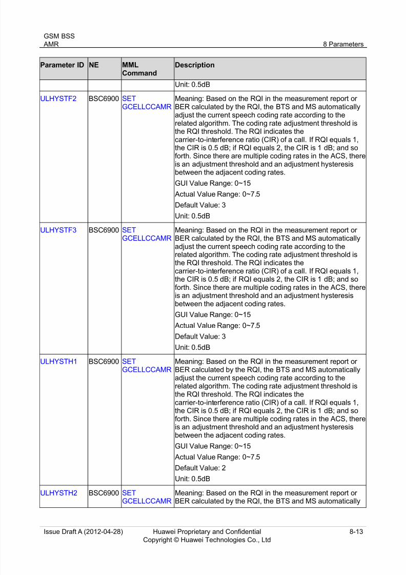
ULHYSTF2 BSC6900 SETGCELLCCAMR Meaning: Based on the RQI in the measurement report orBER calculated by the RQI, the BTS and MS automaticallyadjust the current speech coding rate according to therelated algorithm. The coding rate adjustment threshold isthe RQI threshold. The RQI indicates thecarrier-to-interference ratio (CIR) of a call. If RQI equals 1,the CIR is 0.5 dB; if RQI equals 2, the CIR is 1 dB; and soforth. Since there are multiple coding rates in the ACS, thereis an adjustment threshold and an adjustment hysteresisbetween the adjacent coding rates.
GUI Value Range: 0~15
Actual Value Range: 0~7.5
Default Value: 3
Unit: 0.5dB
ULHYSTF3 BSC6900 SETGCELLCCAMR
Meaning: Based on the RQI in the measurement report orBER calculated by the RQI, the BTS and MS automaticallyadjust the current speech coding rate according to therelated algorithm. The coding rate adjustment threshold isthe RQI threshold. The RQI indicates thecarrier-to-interference ratio (CIR) of a call. If RQI equals 1,the CIR is 0.5 dB; if RQI equals 2, the CIR is 1 dB; and soforth. Since there are multiple coding rates in the ACS, thereis an adjustment threshold and an adjustment hysteresis
between the adjacent coding rates.
GUI Value Range: 0~15
Actual Value Range: 0~7.5
Default Value: 3
Unit: 0.5dB
ULHYSTH1 BSC6900 SETGCELLCCAMR
Meaning: Based on the RQI in the measurement report orBER calculated by the RQI, the BTS and MS automaticallyadjust the current speech coding rate according to therelated algorithm. The coding rate adjustment threshold isthe RQI threshold. The RQI indicates the
carrier-to-interference ratio (CIR) of a call. If RQI equals 1,the CIR is 0.5 dB; if RQI equals 2, the CIR is 1 dB; and soforth. Since there are multiple coding rates in the ACS, thereis an adjustment threshold and an adjustment hysteresisbetween the adjacent coding rates.
GUI Value Range: 0~15
Actual Value Range: 0~7.5
Default Value: 2
Unit: 0.5dB
ULHYSTH2 BSC6900 SET
GCELLCCAMR
Meaning: Based on the RQI in the measurement report or
BER calculated by the RQI, the BTS and MS automatically

8/12/2019 AMR(GBSS14.0_01)
http://slidepdf.com/reader/full/amrgbss14001 35/41
GSM BSS
AMR 8 Parameters
Issue Draft A (2012-04-28) Huawei Proprietary and Confidential
Copyright © Huawei Technologies Co., Ltd
8-14
Parameter ID NE MMLCommand
Description
adjust the current speech coding rate according to therelated algorithm. The coding rate adjustment threshold is
the RQI threshold. The RQI indicates thecarrier-to-interference ratio (CIR) of a call. If RQI equals 1,the CIR is 0.5 dB; if RQI equals 2, the CIR is 1 dB; and soforth. Since there are multiple coding rates in the ACS, thereis an adjustment threshold and an adjustment hysteresisbetween the adjacent coding rates.
GUI Value Range: 0~15
Actual Value Range: 0~7.5
Default Value: 2
Unit: 0.5dB
ULHYSTH3 BSC6900 SETGCELLCCAMR
Meaning: Based on the RQI in the measurement report orBER calculated by the RQI, the BTS and MS automaticallyadjust the current speech coding rate according to therelated algorithm. The coding rate adjustment threshold isthe RQI threshold. The RQI indicates thecarrier-to-interference ratio (CIR) of a call. If RQI equals 1,the CIR is 0.5 dB; if RQI equals 2, the CIR is 1 dB; and soforth. Since there are multiple coding rates in the ACS, thereis an adjustment threshold and an adjustment hysteresisbetween the adjacent coding rates.
GUI Value Range: 0~15
Actual Value Range: 0~7.5
Default Value: 15
Unit: 0.5dB
ULTHF1 BSC6900 SETGCELLCCAMR
Meaning: Based on the RQI in the measurement report orBER calculated by the RQI, the BTS and MS automaticallyadjust the current speech coding rate according to therelated algorithm. The coding rate adjustment threshold isthe RQI threshold. The RQI indicates thecarrier-to-interference ratio (CIR) of a call. If RQI equals 1,the CIR is 0.5 dB; if RQI equals 2, the CIR is 1 dB; and soforth. Since there are multiple coding rates in the ACS, thereis an adjustment threshold and an adjustment hysteresis
between the adjacent coding rates.
GUI Value Range: 0~63
Actual Value Range: 0~31.5
Default Value: 14
Unit: 0.5dB
ULTHF2 BSC6900 SETGCELLCCAMR
Meaning: Based on the RQI in the measurement report orBER calculated by the RQI, the BTS and MS automaticallyadjust the current speech coding rate according to therelated algorithm. The coding rate adjustment threshold isthe RQI threshold. The RQI indicates the
carrier-to-interference ratio (CIR) of a call. If RQI equals 1,

8/12/2019 AMR(GBSS14.0_01)
http://slidepdf.com/reader/full/amrgbss14001 36/41
GSM BSS
AMR 8 Parameters
Issue Draft A (2012-04-28) Huawei Proprietary and Confidential
Copyright © Huawei Technologies Co., Ltd
8-15
Parameter ID NE MMLCommand
Description
the CIR is 0.5 dB; if RQI equals 2, the CIR is 1 dB; and soforth. Since there are multiple coding rates in the ACS, there
is an adjustment threshold and an adjustment hysteresisbetween the adjacent coding rates.
GUI Value Range: 0~63
Actual Value Range: 0~31.5
Default Value: 18
Unit: 0.5dB
ULTHF3 BSC6900 SETGCELLCCAMR
Meaning: Based on the RQI in the measurement report orBER calculated by the RQI, the BTS and MS automaticallyadjust the current speech coding rate according to therelated algorithm. The coding rate adjustment threshold is
the RQI threshold. The RQI indicates thecarrier-to-interference ratio (CIR) of a call. If RQI equals 1,the CIR is 0.5 dB; if RQI equals 2, the CIR is 1 dB; and soforth. Since there are multiple coding rates in the ACS, thereis an adjustment threshold and an adjustment hysteresisbetween the adjacent coding rates.
GUI Value Range: 0~63
Actual Value Range: 0~31.5
Default Value: 24
Unit: 0.5dB
ULTHH1 BSC6900 SETGCELLCCAMR
Meaning: Based on the RQI in the measurement report orBER calculated by the RQI, the BTS and MS automaticallyadjust the current speech coding rate according to therelated algorithm. The coding rate adjustment threshold isthe RQI threshold. The RQI indicates thecarrier-to-interference ratio (CIR) of a call. If RQI equals 1,the CIR is 0.5 dB; if RQI equals 2, the CIR is 1 dB; and soforth. Since there are multiple coding rates in the ACS, thereis an adjustment threshold and an adjustment hysteresisbetween the adjacent coding rates.
GUI Value Range: 0~63
Actual Value Range: 0~31.5
Default Value: 20
Unit: 0.5dB
ULTHH2 BSC6900 SETGCELLCCAMR
Meaning: Based on the RQI in the measurement report orBER calculated by the RQI, the BTS and MS automaticallyadjust the current speech coding rate according to therelated algorithm. The coding rate adjustment threshold isthe RQI threshold. The RQI indicates thecarrier-to-interference ratio (CIR) of a call. If RQI equals 1,the CIR is 0.5 dB; if RQI equals 2, the CIR is 1 dB; and soforth. Since there are multiple coding rates in the ACS, thereis an adjustment threshold and an adjustment hysteresis
between the adjacent coding rates.

8/12/2019 AMR(GBSS14.0_01)
http://slidepdf.com/reader/full/amrgbss14001 37/41
GSM BSS
AMR 8 Parameters
Issue Draft A (2012-04-28) Huawei Proprietary and Confidential
Copyright © Huawei Technologies Co., Ltd
8-16
Parameter ID NE MMLCommand
Description
GUI Value Range: 0~63
Actual Value Range: 0~31.5
Default Value: 26
Unit: 0.5dB
ULTHH3 BSC6900 SETGCELLCCAMR
Meaning: Based on the RQI in the measurement report orBER calculated by the RQI, the BTS and MS automaticallyadjust the current speech coding rate according to therelated algorithm. The coding rate adjustment threshold isthe RQI threshold. The RQI indicates thecarrier-to-interference ratio (CIR) of a call. If RQI equals 1,the CIR is 0.5 dB; if RQI equals 2, the CIR is 1 dB; and soforth. Since there are multiple coding rates in the ACS, thereis an adjustment threshold and an adjustment hysteresisbetween the adjacent coding rates.
GUI Value Range: 0~63
Actual Value Range: 0~31.5
Default Value: 63
Unit: 0.5dB
UMSFRSWITCH
BSC6900 SETGCELLCCBASIC
Meaning: Switch for Um interface speech frame repair. Whenthis parameter is set to YES, Um interface speech framerepair is enabled. When this parameter is set to NO, Uminterface speech frame repair is disabled.
GUI Value Range: NO(No), YES(Yes)
Actual Value Range: NO, YES
Default Value: NO(No)
Unit: None
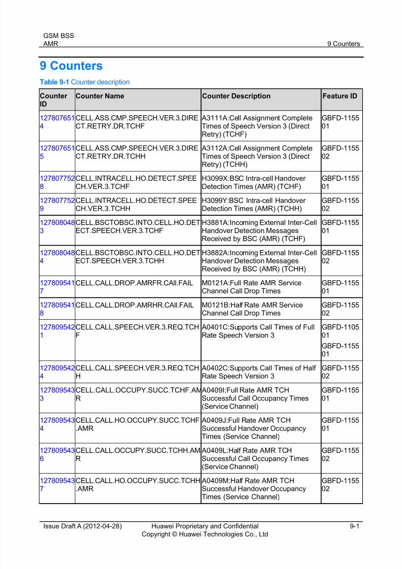
8/12/2019 AMR(GBSS14.0_01)
http://slidepdf.com/reader/full/amrgbss14001 38/41
GSM BSS
AMR 9 Counters
Issue Draft A (2012-04-28) Huawei Proprietary and Confidential
Copyright © Huawei Technologies Co., Ltd
9-1
9 Counters
Table 9-1 Counter description
CounterID Counter Name Counter Description Feature ID
1278076514
CELL.ASS.CMP.SPEECH.VER.3.DIRECT.RETRY.DR.TCHF
A3111A:Cell Assignment CompleteTimes of Speech Version 3 (DirectRetry) (TCHF)
GBFD-115501
1278076515
CELL.ASS.CMP.SPEECH.VER.3.DIRECT.RETRY.DR.TCHH
A3112A:Cell Assignment CompleteTimes of Speech Version 3 (DirectRetry) (TCHH)
GBFD-115502
1278077528
CELL.INTRACELL.HO.DETECT.SPEECH.VER.3.TCHF
H3099X:BSC Intra-cell HandoverDetection Times (AMR) (TCHF)
GBFD-115501
1278077529
CELL.INTRACELL.HO.DETECT.SPEECH.VER.3.TCHH
H3099Y:BSC Intra-cell HandoverDetection Times (AMR) (TCHH)
GBFD-115502
1278080483
CELL.BSCTOBSC.INTO.CELL.HO.DETECT.SPEECH.VER.3.TCHF
H3881A:Incoming External Inter-CellHandover Detection MessagesReceived by BSC (AMR) (TCHF)
GBFD-115501
1278080484
CELL.BSCTOBSC.INTO.CELL.HO.DETECT.SPEECH.VER.3.TCHH
H3882A:Incoming External Inter-CellHandover Detection MessagesReceived by BSC (AMR) (TCHH)
GBFD-115502
1278095417
CELL.CALL.DROP.AMRFR.CAll.FAIL M0121A:Full Rate AMR ServiceChannel Call Drop Times
GBFD-115501
1278095418
CELL.CALL.DROP.AMRHR.CAll.FAIL M0121B:Half Rate AMR ServiceChannel Call Drop Times
GBFD-115502
1278095421
CELL.CALL.SPEECH.VER.3.REQ.TCHF
A0401C:Supports Call Times of FullRate Speech Version 3
GBFD-110501
GBFD-115501
1278095424
CELL.CALL.SPEECH.VER.3.REQ.TCHH
A0402C:Supports Call Times of HalfRate Speech Version 3
GBFD-115502
127809543
3
CELL.CALL.OCCUPY.SUCC.TCHF.AM
R
A0409I:Full Rate AMR TCH
Successful Call Occupancy Times(Service Channel)
GBFD-1155
01
1278095434
CELL.CALL.HO.OCCUPY.SUCC.TCHF.AMR
A0409J:Full Rate AMR TCHSuccessful Handover OccupancyTimes (Service Channel)
GBFD-115501
1278095436
CELL.CALL.OCCUPY.SUCC.TCHH.AMR
A0409L:Half Rate AMR TCHSuccessful Call Occupancy Times(Service Channel)
GBFD-115502
1278095437
CELL.CALL.HO.OCCUPY.SUCC.TCHH.AMR
A0409M:Half Rate AMR TCHSuccessful Handover Occupancy
Times (Service Channel)
GBFD-115502

8/12/2019 AMR(GBSS14.0_01)
http://slidepdf.com/reader/full/amrgbss14001 39/41
GSM BSS
AMR 9 Counters
Issue Draft A (2012-04-28) Huawei Proprietary and Confidential
Copyright © Huawei Technologies Co., Ltd
9-2
CounterID
Counter Name Counter Description Feature ID
1278095438
CELL.CALL.DROP.CALL.RATE.TCHF. AMR
A0409N:Full Rate AMR Call DropRate
GBFD-115501
1278095439
CELL.CALL.DROP.CALL.RATE.TCHH. AMR
A0409P:Half Rate AMR Call DropRate
GBFD-115502
1278271449
CELL.AMR.MS.PWR.LEV.AVE AS3240A:Average MS Power Level of AMR Call
GBFD-115503
GBFD-115502
GBFD-115501
127827145
0
CELL.AMR.BTS.PWR.LEV.AVE AS3241A:Average BTS Power Level
of AMR Call
GBFD-1155
03GBFD-115502
GBFD-115501
1278473476
CELL.CHAN.BUSY.NUM.TCHF.AMR.TRAF.AVE
AR3551C:Traffic Volume on AMRTCHFs
GBFD-115501
1278473477
CELL.CHAN.BUSY.NUM.TCHH.AMR.TRAF.AVE
AR3552C:Traffic Volume on AMRTCHHs
GBFD-115502
1282423819
CELL.CHAN.BUSY.NUM.TCHF.AMR.TRAF.OVERLAY.AVE
AR3559C:Traffic Volume on AMRTCHFs (Overlaid Subcell)
GBFD-115501
GBFD-113201
1282423822
CELL.CHAN.BUSY.NUM.TCHH.AMR.TRAF.OVERLAY.AVE
AR3560C:Traffic Volume on AMRTCHHs (Overlaid Subcell)
GBFD-115502
GBFD-113201

8/12/2019 AMR(GBSS14.0_01)
http://slidepdf.com/reader/full/amrgbss14001 40/41
GSM BSS
AMR 10 Glossary
Issue Draft A (2012-04-28) Huawei Proprietary and Confidential
Copyright © Huawei Technologies Co., Ltd
10-1
10 Glossary
For the acronyms, abbreviations, terms, and definitions, see the Glossary .

8/12/2019 AMR(GBSS14.0_01)
http://slidepdf.com/reader/full/amrgbss14001 41/41
GSM BSS
AMR 11 Reference Documents
11 Reference Documents
[1] GSM 05.03: "Digital cellular telecommunications system (Phase 2+); Channel coding"
[2] GSM 05.09: "Digital cellular telecommunications system (Phase 2+); Link Adaptation"
[3] GSM 04.08: "Digital cellular telecommunications system (Phase 2+); Mobile radio interface layer 3specification"
[4] GSM 06.90: "Digital cellular telecommunications system (Phase 2+); Adaptive Multi-Rate (AMR)speech transcoding "
[5] GSM 06.91: "Digital cellular telecommunications system (Phase 2+); Substitution and muting of lostframes for Adaptive Multi Rate (AMR) speech traffic channels "
[6] GSM 06.92: "Digital cellular telecommunications system (Phase 2+); Comfort noise aspects for Adaptive Multi-Rate (AMR) speech traffic channels "
[7] GSM 06.93: "Digital cellular telecommunications system (Phase 2+); Discontinuous transmission(DTX) for Adaptive Multi Rate (AMR) speech traffic channels "
[8] GSM 06.94: "Digital cellular telecommunications system (Phase 2+); Voice Activity Detection (VAD)for Adaptive Multi-Rate speech traffic channels "
[9] GSM 08.08: "Digital cellular telecommunications system (Phase 2+); Mobile-services SwitchingCentre - Base Station System (MSC - BSS) interface; Layer 3 specification "
[10] GSM 08.58: "Digital cellular telecommunications system (Phase 2+); Base Station Controller - BaseTransceiver Station (BSC - BTS) interface; Layer 3 specification "
[11] GSM 08.60: "Digital cellular telecommunications system (Phase 2+); In-band control of remotetranscoders and rate adaptors for full rate traffic channels "
[12] GSM 08.61: "Digital cellular telecommunications system (Phase 2+); In-band control of remotetranscoders and rate adaptors for half rate traffic channels "
[13] BSC6900 Feature List
[14] BSC6900 Optional Feature Description
[15] BSC6900 GSM Parameter Reference
[16] BSC6900 GSM MML Command Reference
[17] BSC6900 GSM Performance Counter Reference
[18] Power Control Feature Parameter Description
[19] Discontinuous Transmission and Discontinuous Reception Feature Parameter Description
[20] TFO Feature Parameter Description
[21] Handover Feature Parameter Description