Embed Size (px)
Citation preview
Introduction
• Amplitude Modulation System
• Angle Modulation System
Frequency Modulation
Phase Modulation
• Digital Communication
• Elements of Information Theory
• Advanced Communication Techniques
1
Tools for communication
• Fourier Series
• Fourier Transform
Fourier Series
• Every composite periodic signal can be represented with a series of sine and cosine functions.
• The functions are integral harmonics of the fundamental frequency “f” of the composite signal.
• Using the series we can decompose any periodic signal into its harmonics.
periodic signal
• Periodic signals repeat with some period T, while aperiodic, or non periodic, signals do not. We can define a periodic function through the following mathematical expression, where t can be any number and T is a positive constant:
• f(t) =f(T + t) (1) …………………..(1)
• The fundamental period of our function, f(t) , is the smallest value of T that the still allows equation-1 to be true.
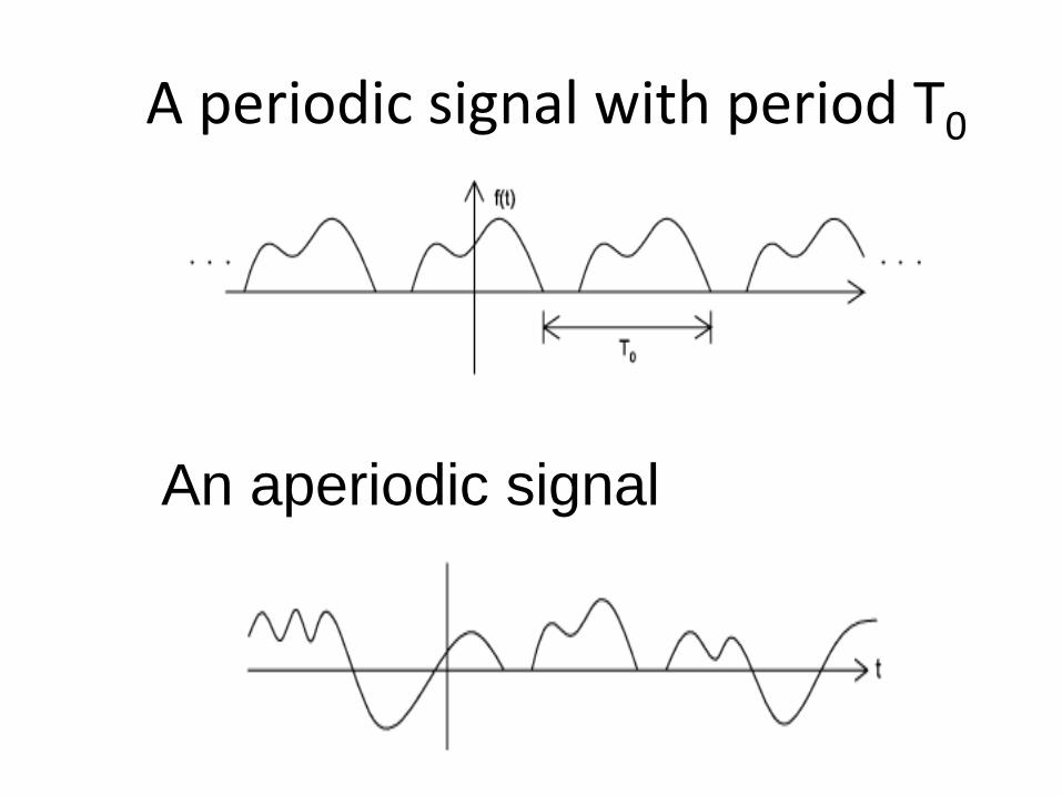
A periodic signal with period T0
An aperiodic signal
Fourier Transform
• Fourier Transform is a tool that changes a
time domain signal to a frequency domain
signal and vice versa.
Why frequency domain analysis?
Allows simple algebra rather than time-domain
differential equations to be used
Transfer functions can be applied to transmitter, communication channel and receiver
Channel bandwidth, noise and power are easier to evaluate
Easy to pick out frequencies.
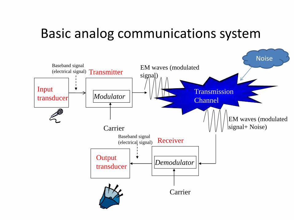
Basic analog communications system
Modulator
Demodulator
Transmission
Channel
Input
transducer
Transmitter
Receiver
Output
transducer
Carrier
EM waves (modulated
signal)
EM waves (modulated
signal+ Noise)
Baseband signal
(electrical signal)
Baseband signal
(electrical signal)
Carrier
Noise
Introduction
• Definition of COMMUNICATION? • Why do we need to communicate? • Definition of COMMUNICATION SYSTEM
(Electronic Communication System)? • Why do we need to communicate
electronically? • How to communicate? • Interference in communications? How to
overcome?
9
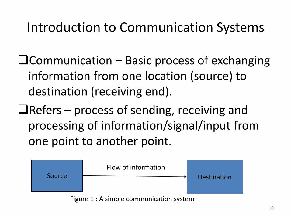
Introduction to Communication Systems
Communication – Basic process of exchanging information from one location (source) to destination (receiving end).
Refers – process of sending, receiving and processing of information/signal/input from one point to another point.
Source Destination
Flow of information
Figure 1 : A simple communication system 10
Electronic Communication System – defined as the whole mechanism of sending and receiving as well as processing of information electronically from source to destination.
Example – Radiotelephony, broadcasting, point-to-point, mobile communications, computer communications, radar and satellite systems.
11
Objectives
Communication System – to produce an accurate replica of the transmitted information that is to transfer information between two or more points (destinations) through a communication channel, with minimum error.
Besides – interactive purposes, business and social
12
NEED FOR COMMUNICATION
Interaction purposes – enables people to interact in a timely fashion on a global level in social, political, economic and scientific areas, through telephones, electronic-mail and video conference.
Transfer Information – Tx in the form of audio, video,
texts, computer data and picture through facsimile, telegraph or telex and internet.
Broadcasting – Broadcast information to masses,
through radio, television or teletext.
13
Terms Related To Communications
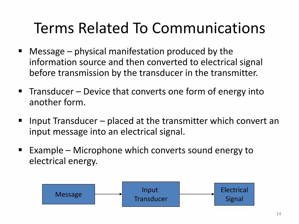
Message – physical manifestation produced by the information source and then converted to electrical signal before transmission by the transducer in the transmitter.
Transducer – Device that converts one form of energy into another form.
Input Transducer – placed at the transmitter which convert an input message into an electrical signal.
Example – Microphone which converts sound energy to electrical energy.
Message Input
Transducer Electrical
Signal
14
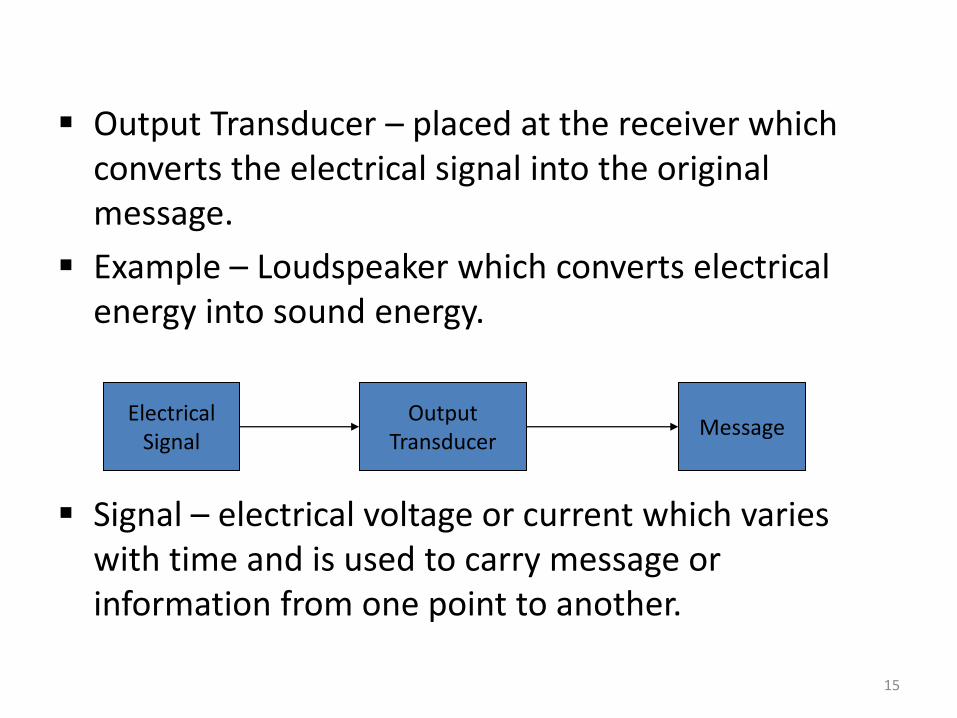
Output Transducer – placed at the receiver which converts the electrical signal into the original message.
Example – Loudspeaker which converts electrical energy into sound energy.
Signal – electrical voltage or current which varies with time and is used to carry message or information from one point to another.
Electrical Signal
Output Transducer
Message
15
Information – defined as what is being conveyed by the telecommunication environment or as knowledge or facts. It can be in analogue form (voice, video, music) or digital form ( binary-coded numbers, graphics symbols or database information).
16
Basic Requirements of Communication Systems.
Rate of Information Transfer – defined as the amount of info that must be communicated from source to destination in a certain period of time. It determines the physical form and the techniques used to transmit and receive information.
The rate of information transfer must be reasonable and acceptable rate for each communication system.
17
Purity of Received Signal – the received signal must be the same as the transmitted signal
Simplicity of the system – must be convenience in order to be effective and efficient/easy to use.
Reliability – User must be able to depend on a communication system. It must work when needed and transmit/receive information without errors or with an acceptable errors.
18
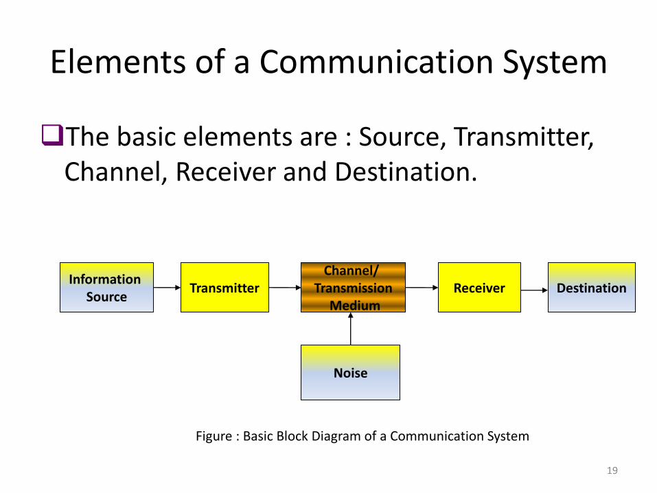
Elements of a Communication System
The basic elements are : Source, Transmitter, Channel, Receiver and Destination.
Information Source
Transmitter Channel/
Transmission Medium
Receiver Destination
Noise
Figure : Basic Block Diagram of a Communication System
19
Function of each Element.
Information Source – the communication system exists to send messages. Messages come from voice, data, video and other types of information.
Transmitter – Transmit the input message into electrical signals such as voltage or current into electromagnetic waves such as radio waves, microwaves that is suitable for transmission and compatible with the channel. Besides, the transmitter also do the modulation and encoding (for digital signal).
20
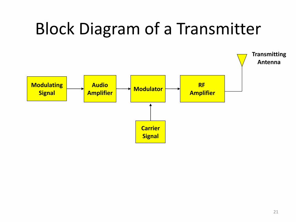
Block Diagram of a Transmitter
Modulating Signal
Audio Amplifier
Modulator RF
Amplifier
Carrier Signal
Transmitting Antenna
21
Channel/Medium – is the link or path over which information flows from the source to destination. Many links combined will establish a communication networks.
There are 5 criteria of a transmission system; Capacity, Performance, Distance, Security and Cost which includes the installation, operation and maintenance.
2 main categories of channel that commonly used are; line (guided media) and free space (unguided media)
22
Receiver – Receives the electrical signals or electromagnetic waves that are sent by the transmitter through the channel. It is also separate the information from the received signal and sent the information to the destination.
Basically, a receiver consists of several stages of amplification, frequency conversion and filtering.
23
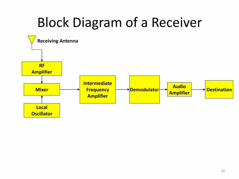
Block Diagram of a Receiver
RF Amplifier
Mixer
Local Oscillator
Intermediate Frequency Amplifier
Demodulator Audio
Amplifier Destination
Receiving Antenna
24
Limitations in a Communication System
• There are 2 categories of limitations:-
– Technological
– Physical
• Technological Constraint includes equipment availability, economy and cost factor, national and international law (ITU-T) and interaction with existing systems.
• Physical Constraint includes bandwidth and noise.
25
Cont…….physical constraint • Bandwidth – defined as the information carrying capacity of a
system or the frequency content of a signal. • BW is the difference between the upper frequency fH and the
lower frequency fL of the signal. • Example: The voice frequency ranges from 300 Hz to 3400 Hz.
Therefore, the BW is 3.1 kHz. • The limitation due to BW is applied to both signals and
systems as a measure of speed. Means that the shorter transmission time will result in high-speed transmission of the signal, which require large BW and hence increasing the cost of the system
26
Cont…….physical constraint
• Noise – defined as unwanted electrical energy present in the usable passband of a communication circuit. It is unavoidable.
• Noise is measured in terms of Signal-to-Noise ratio (SNR). • Its limitation, Higher SNR…..higher transmitted power and
higher cost. • Noise Factor, denoted by F and defined as the ratio of SNR at
the input to the SNR at the output of a network. – F = (SNR)input / (SNR)output – Noise Figure = 10 log F dB
• Noise figure or noise factor is used to compare the performance of a communication system. Higher SNR, lower F is better in a communication systems.
27
Unit-1
Amplitude Modulation System
28
29
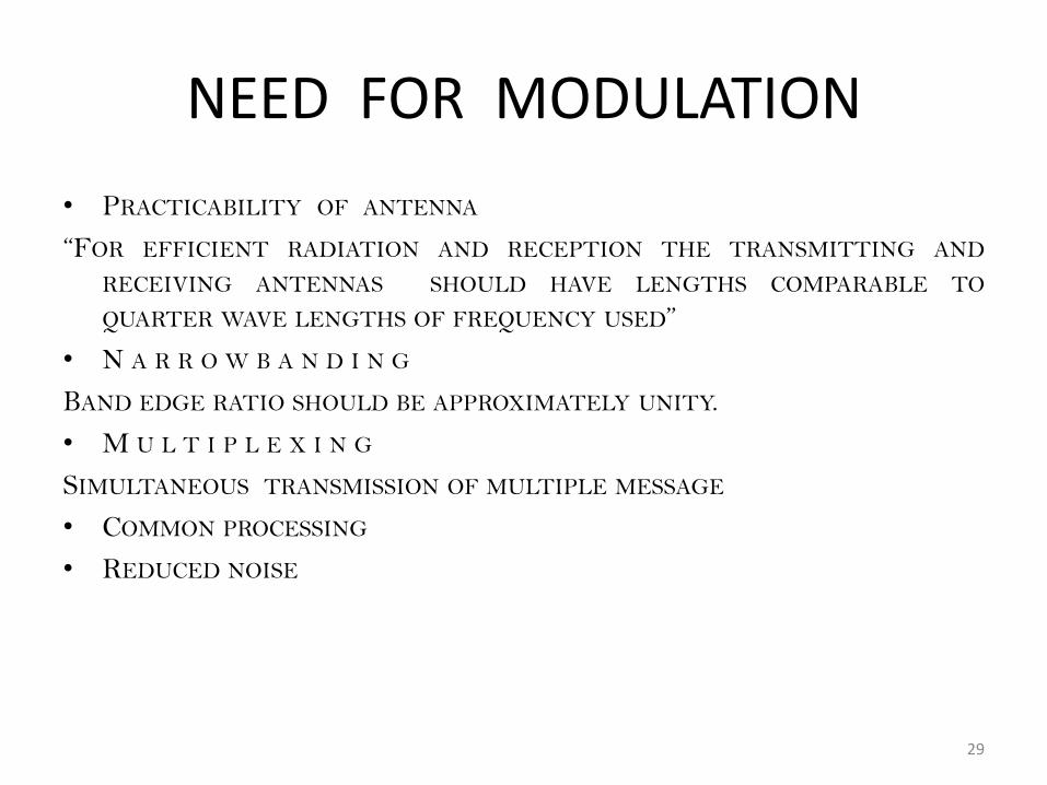
NEED FOR MODULATION
• PRACTICABILITY OF ANTENNA
“FOR EFFICIENT RADIATION AND RECEPTION THE TRANSMITTING AND
RECEIVING ANTENNAS SHOULD HAVE LENGTHS COMPARABLE TO
QUARTER WAVE LENGTHS OF FREQUENCY USED”
• N A R R O W B A N D I N G
BAND EDGE RATIO SHOULD BE APPROXIMATELY UNITY.
• M U L T I P L E X I N G
SIMULTANEOUS TRANSMISSION OF MULTIPLE MESSAGE
• COMMON PROCESSING
• REDUCED NOISE
Amplitude Modulation
30
Amplitude Modulation
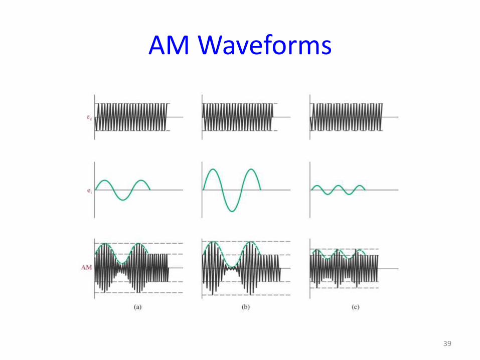
• Amplitude Modulation is the process of changing the amplitude of a relatively high frequency carrier signal in proportion with the instantaneous value of the modulating signal (information).
• Use in commercial broadcasting of both audio and video signals.
• Also used for two-way mobile radio communications, such as citizens band (CB) radio.
31

AM Waveforms
32
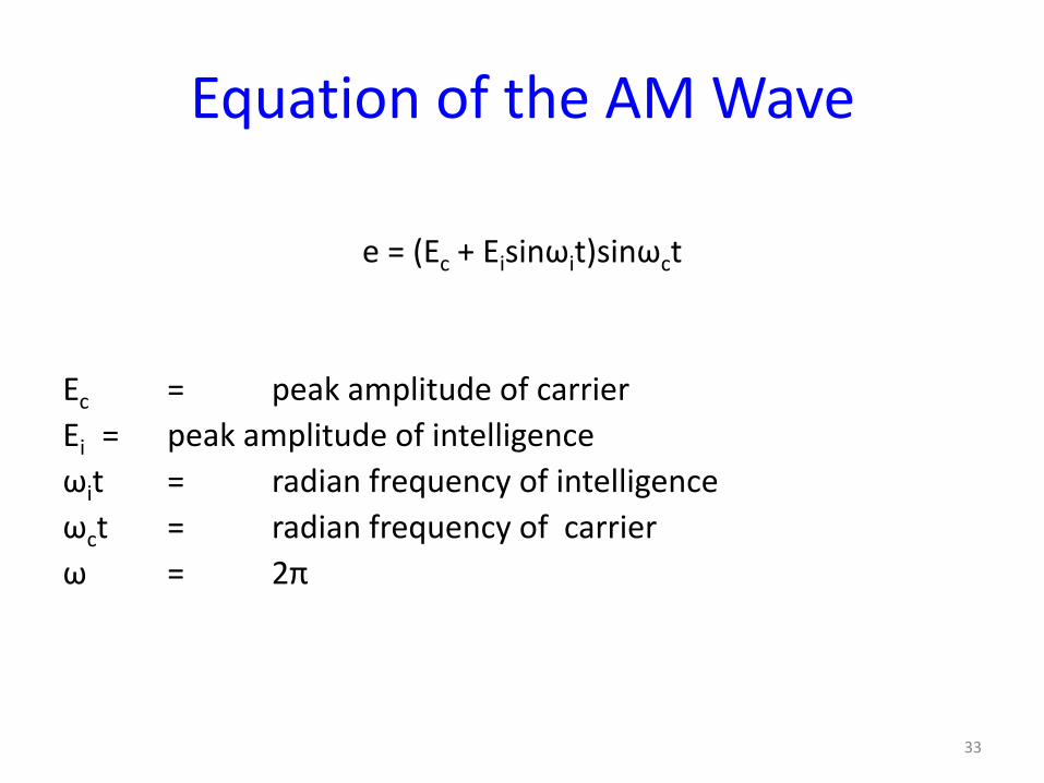
Equation of the AM Wave
e = (Ec + Eisinωit)sinωct
Ec = peak amplitude of carrier
Ei = peak amplitude of intelligence
ωit = radian frequency of intelligence
ωct = radian frequency of carrier
ω = 2π
33
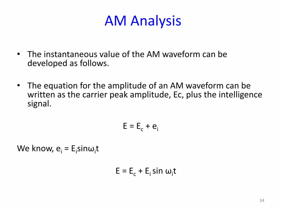
AM Analysis
• The instantaneous value of the AM waveform can be developed as follows.
• The equation for the amplitude of an AM waveform can be written as the carrier peak amplitude, Ec, plus the intelligence signal.
E = Ec + ei
We know, ei = Eisinωit
E = Ec + Ei sin ωit
34
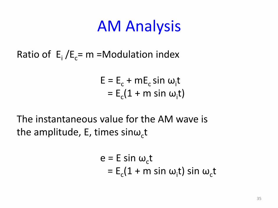
AM Analysis
Ratio of Ei /Ec= m =Modulation index
E = Ec + mEc sin ωit = Ec(1 + m sin ωit) The instantaneous value for the AM wave is the amplitude, E, times sinωct e = E sin ωct = Ec(1 + m sin ωit) sin ωct
35
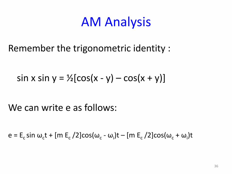
AM Analysis
Remember the trigonometric identity :
sin x sin y = ½[cos(x - y) – cos(x + y)]
We can write e as follows:
e = Ec sin ωct + [m Ec /2]cos(ωc - ωi)t – [m Ec /2]cos(ωc + ωi)t
36
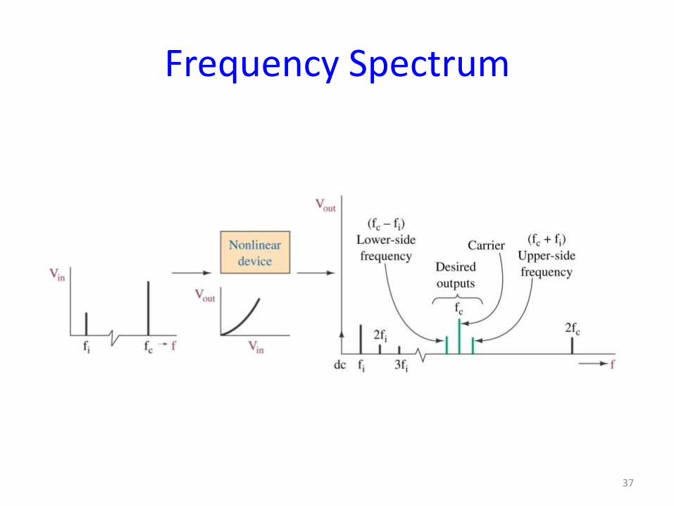
Frequency Spectrum
37
The AM Waveform
The three components that form the AM
waveform are listed below:
1. The lower-side frequency (fc - fi)
2. The carrier frequency (fc)
3. The upper-side frequency (fc + fi)
38
AM Waveforms
39
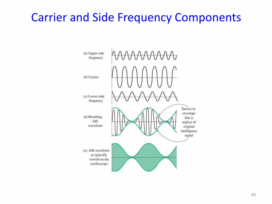
Carrier and Side Frequency Components
40
Upper and Lower Sidebands
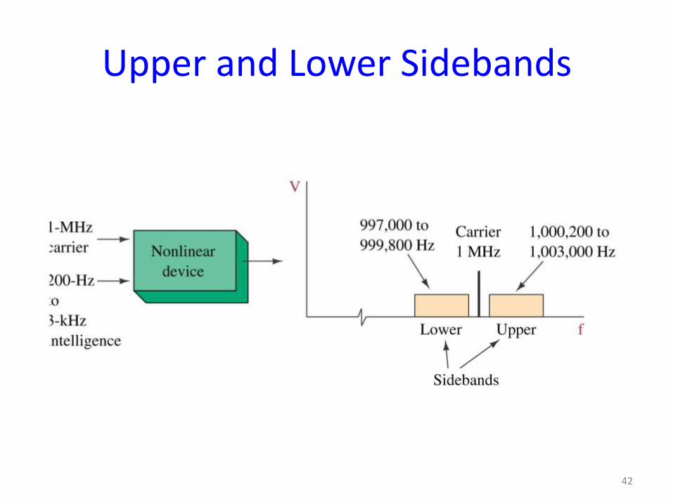
• In most systems the intelligence signal is a complex waveform containing components from roughly 200Hz to 3KHz.
• If this is used to modulate the carrier there would be a whole band of side frequencies.
• The band of frequencies above the carrier is term the upper sideband.
• The band of frequencies below the carrier is called the lower sideband.
41
Upper and Lower Sidebands
42
Example
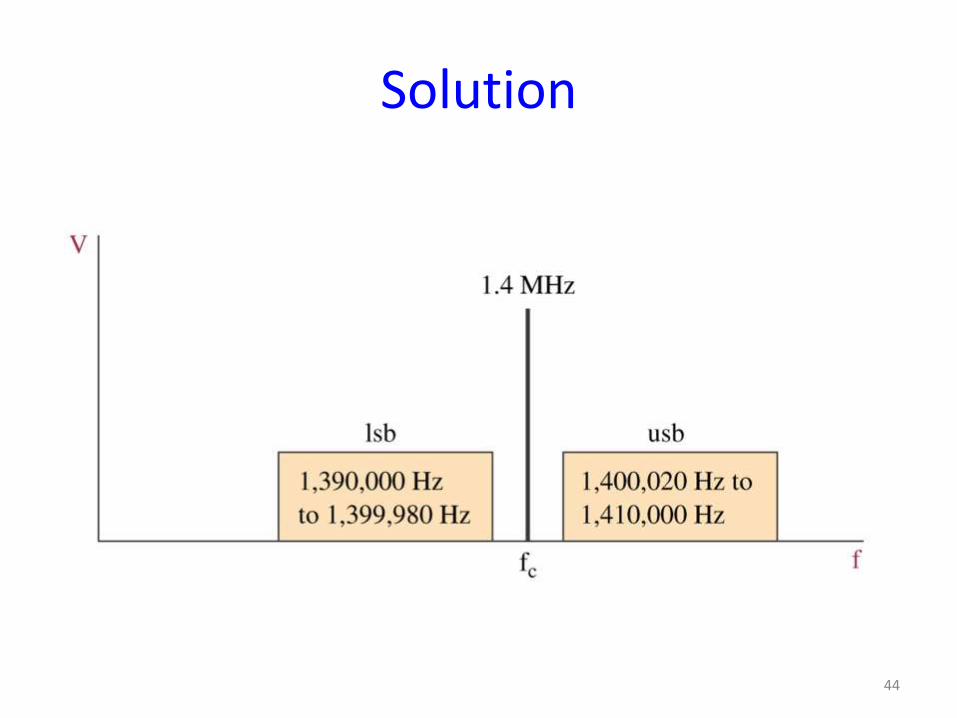
A 1.4MHz carrier is modulated by a music
signal that has frequency components from
20Hz to 10kHz. Determine the range of
frequencies generated for the upper and
lower sidebands.
43
Solution
44
Modulation index (m)
0 0.001 0.002 0.003 0.004 0.005 0.006 0.007 0.008 0.009 0.01-2
-1.5
-1
-0.5
0
0.5
1
1.5
2
Time (sec)
Vo
ltag
e (V
)
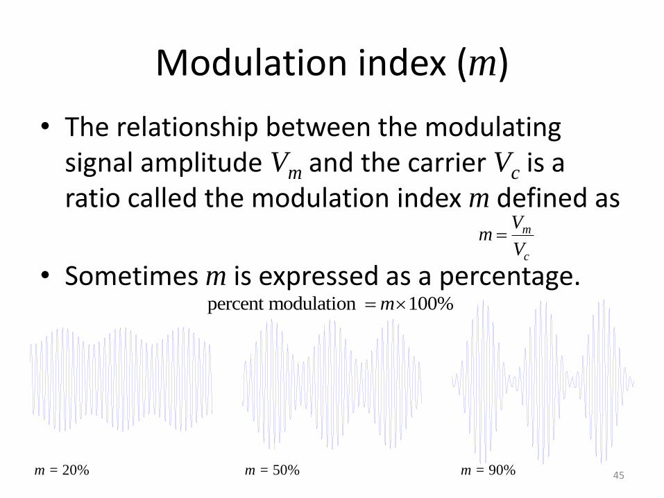
• The relationship between the modulating signal amplitude Vm and the carrier Vc is a ratio called the modulation index m defined as
• Sometimes m is expressed as a percentage.
m
c
Vm
V
0 0.001 0.002 0.003 0.004 0.005 0.006 0.007 0.008 0.009 0.01-2
-1.5
-1
-0.5
0
0.5
1
1.5
2
Time (sec)
Vo
ltag
e (V
)
0 0.001 0.002 0.003 0.004 0.005 0.006 0.007 0.008 0.009 0.01-2
-1.5
-1
-0.5
0
0.5
1
1.5
2
Time (sec)
Vo
ltag
e (V
)
m = 20% m = 50% m = 90%
percent modulation 100%m
45
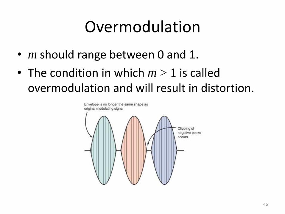
Overmodulation
• m should range between 0 and 1.
• The condition in which m > 1 is called overmodulation and will result in distortion.
46
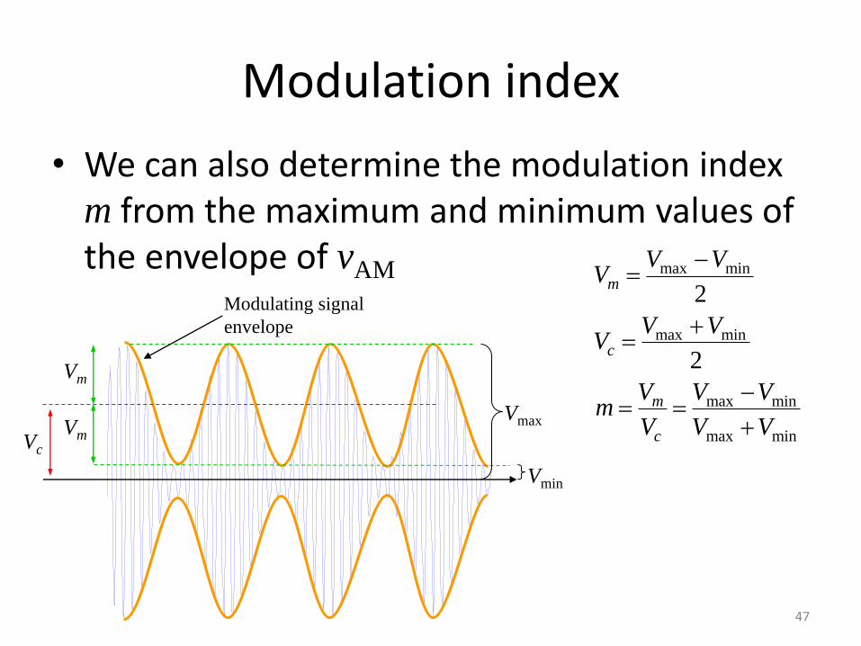
Modulation index
• We can also determine the modulation index m from the maximum and minimum values of the envelope of vAM max min
max min
max min
max min
2
2
m
c
m
c
V VV
V VV
V V Vm
V V V
0 0.001 0.002 0.003 0.004 0.005 0.006 0.007 0.008 0.009 0.01-2
-1.5
-1
-0.5
0
0.5
1
1.5
2
Time (sec)
Vo
ltag
e (V
)
Vc
Vm
Vm
Modulating signal
envelope
Vmin
Vmax
47
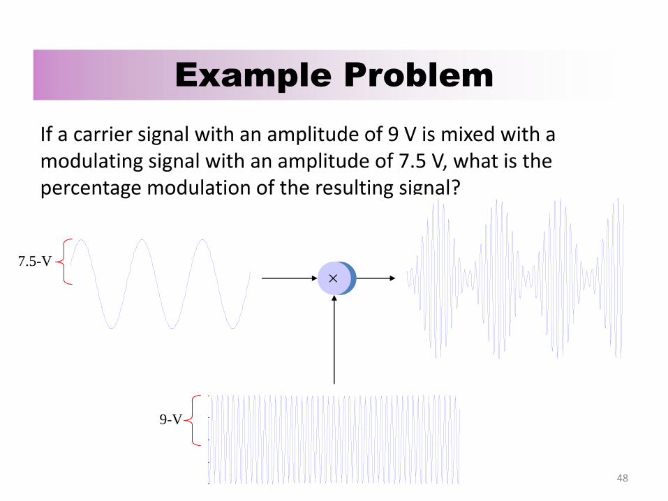
If a carrier signal with an amplitude of 9 V is mixed with a modulating signal with an amplitude of 7.5 V, what is the percentage modulation of the resulting signal?
Example Problem
0 0.001 0.002 0.003 0.004 0.005 0.006 0.007 0.008 0.009 0.01-2
-1.5
-1
-0.5
0
0.5
1
1.5
2
Time (sec)
Vo
ltag
e (V
)
0 0.001 0.002 0.003 0.004 0.005 0.006 0.007 0.008 0.009 0.01-2
-1.5
-1
-0.5
0
0.5
1
1.5
2
Time (sec)
Vo
ltag
e (V
)
0 0.001 0.002 0.003 0.004 0.005 0.006 0.007 0.008 0.009 0.01-2
-1.5
-1
-0.5
0
0.5
1
1.5
2
Time (sec)
Vo
ltag
e (V
)
9-V
7.5-V
48
Percentage Modulation
• A measure of the extent to which a carrier voltage is varied by the intelligent signal.
• Also known as modulation index or modulation factor and is symbolized by m.
0 ≤ m ≤ 1
0 => no modulation 1 => 100% modulation
49

AM Waveforms
50
Example
• An unmodulated carrier is 300V p-p. Calculate %m when its maximum p-p value reaches 400, 500, 600.
51
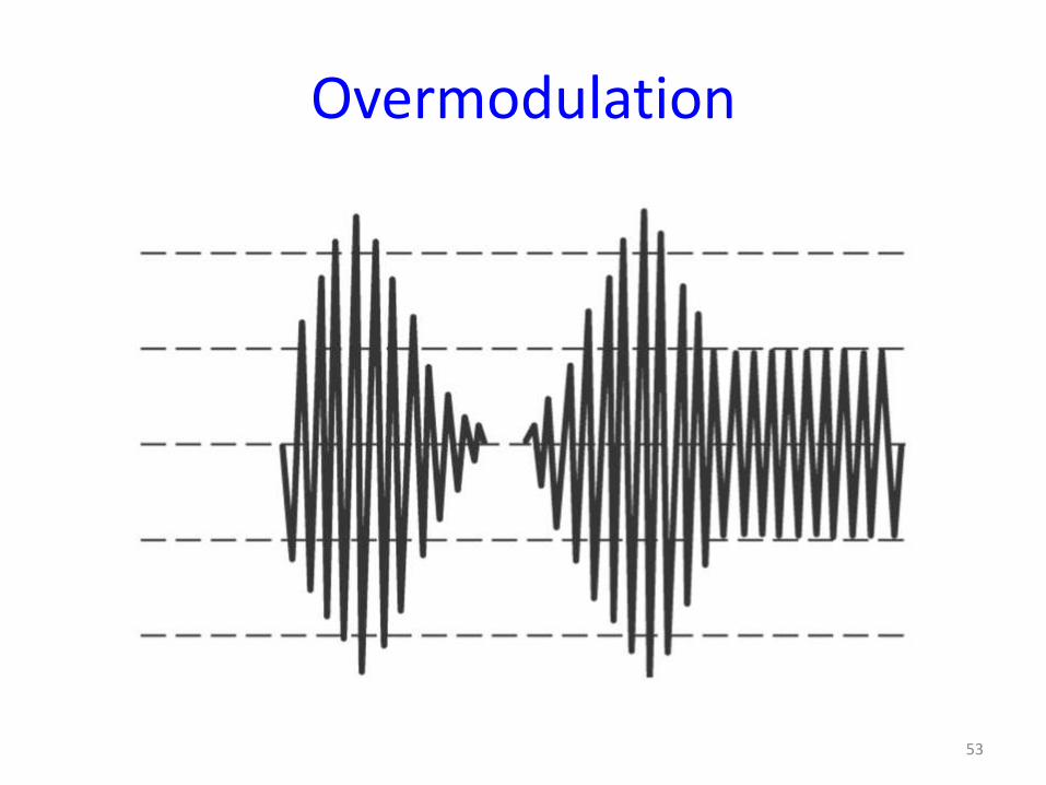
Overmodulation
• When an excessive intelligent signal overdrives an AM modulator producing percentage modulation exceeding 100 percent.
• Overmodulation produces sideband splatter. Distortion resulting in an overmodulated AM transmission creating excessive bandwidths.
52
Overmodulation
53
AM in the frequency domain
0 0.001 0.002 0.003 0.004 0.005 0.006 0.007 0.008 0.009 0.01-2
-1.5
-1
-0.5
0
0.5
1
1.5
2
Time (sec)
Vo
ltag
e (V
)
0 0.001 0.002 0.003 0.004 0.005 0.006 0.007 0.008 0.009 0.01-2
-1.5
-1
-0.5
0
0.5
1
1.5
2
Time (sec)
Vo
ltag
e (V
)
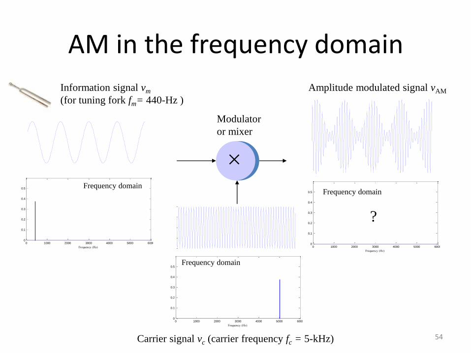
Amplitude modulated signal vAM
0 0.001 0.002 0.003 0.004 0.005 0.006 0.007 0.008 0.009 0.01-2
-1.5
-1
-0.5
0
0.5
1
1.5
2
Time (sec)
Vo
ltag
e (V
)
Carrier signal vc (carrier frequency fc = 5-kHz)
Modulator
or mixer
Information signal vm
(for tuning fork fm= 440-Hz )
0 1000 2000 3000 4000 5000 60000
0.1
0.2
0.3
0.4
0.5
Frequency (Hz)
Vo
ltag
e (V
)
Frequency domain
0 1000 2000 3000 4000 5000 60000
0.1
0.2
0.3
0.4
0.5
Frequency (Hz)
Vo
ltag
e (V
)
Frequency domain
0 1000 2000 3000 4000 5000 60000
0.1
0.2
0.3
0.4
0.5
Frequency (Hz)
Vo
ltag
e (V
)
Frequency domain
?
54
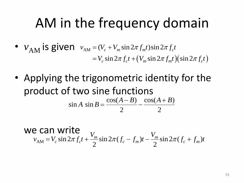
AM in the frequency domain
• vAM is given
• Applying the trigonometric identity for the product of two sine functions we can write
AM ( sin 2 )sin 2
sin 2 sin 2 sin 2
c m m c
c c m m c
v V V f t f t
V f t V f t f t
cos( ) cos( )sin sin
2 2
A B A BA B
AM sin 2 sin 2 ( ) sin 2 ( )2 2
m mc c c m c m
V Vv V f t f f t f f t
55
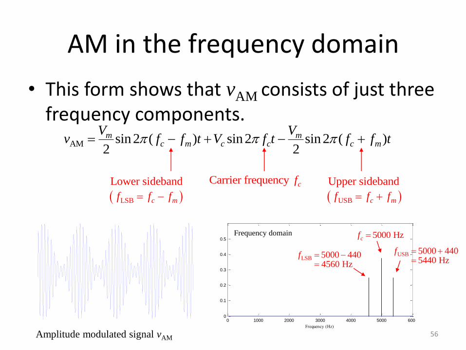
AM in the frequency domain
• This form shows that vAM consists of just three frequency components.
AM sin 2 ( ) sin 2 sin 2 ( )2 2
m mc m c c c m
V Vv f f t V f t f f t
USB
Upper sideband
c mf f f LSB
Lower sideband
c mf f f
Carrier frequency cf
0 0.001 0.002 0.003 0.004 0.005 0.006 0.007 0.008 0.009 0.01-2
-1.5
-1
-0.5
0
0.5
1
1.5
2
Time (sec)
Vo
ltag
e (V
)
Amplitude modulated signal vAM
0 1000 2000 3000 4000 5000 60000
0.1
0.2
0.3
0.4
0.5
Frequency (Hz)
Vo
ltag
e (V
)
Frequency domain
LSB 5000 4404560 Hz
f
USB 5000 4405440 Hz
f
5000 Hzcf
56
Example
• Determine the maximum sideband power if the carrier output is 1 kW and calculate the total maximum transmitted power.
57
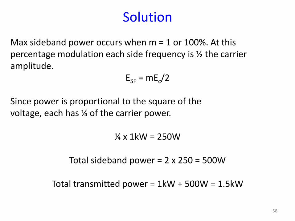
Solution
Max sideband power occurs when m = 1 or 100%. At this percentage modulation each side frequency is ½ the carrier amplitude.
ESF = mEc/2 Since power is proportional to the square of the voltage, each has ¼ of the carrier power.
¼ x 1kW = 250W
Total sideband power = 2 x 250 = 500W
Total transmitted power = 1kW + 500W = 1.5kW
58
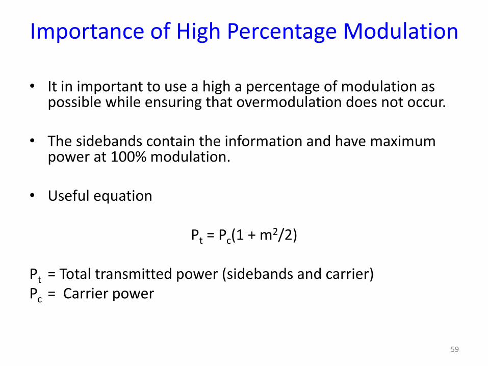
Importance of High Percentage Modulation
• It in important to use a high a percentage of modulation as possible while ensuring that overmodulation does not occur.
• The sidebands contain the information and have maximum power at 100% modulation.
• Useful equation
Pt = Pc(1 + m2/2)
Pt = Total transmitted power (sidebands and carrier) Pc = Carrier power
59
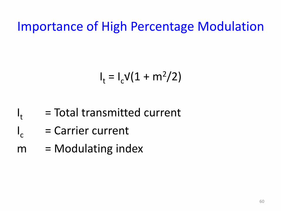
Importance of High Percentage Modulation
It = Ic√(1 + m2/2)
It = Total transmitted current
Ic = Carrier current
m = Modulating index
60
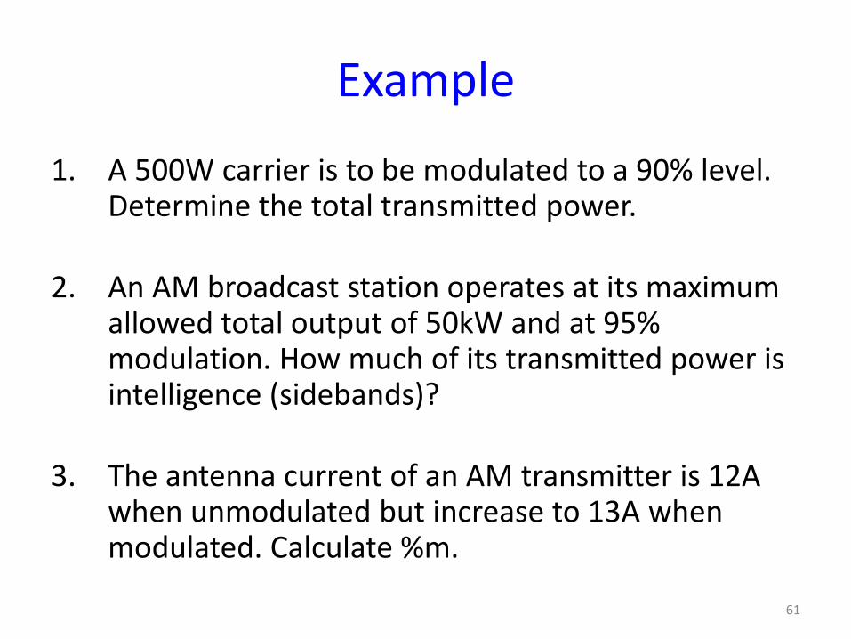
Example
1. A 500W carrier is to be modulated to a 90% level. Determine the total transmitted power.
2. An AM broadcast station operates at its maximum allowed total output of 50kW and at 95% modulation. How much of its transmitted power is intelligence (sidebands)?
3. The antenna current of an AM transmitter is 12A when unmodulated but increase to 13A when modulated. Calculate %m.
61
Effective Modulation Index
If a carrier is modulated by more than a single sine wave, the effective modulation index is given by:
meff = √(m1
2 + m22 + m3
2 +….)
Note that the total modulation index must not exceed 1 or distortion will occur. meff can be used in all previously developed equations using m.
62
Example
• A transmitter with a 10kW carrier transmit 11.2kW when modulated with a single sine wave. Calculate the modulation index. If the carrier is simultaneously modulated with another sine wave at 50 percent modulation, calculate the total transmitted power.
63
Baseband vs Passband Transmission
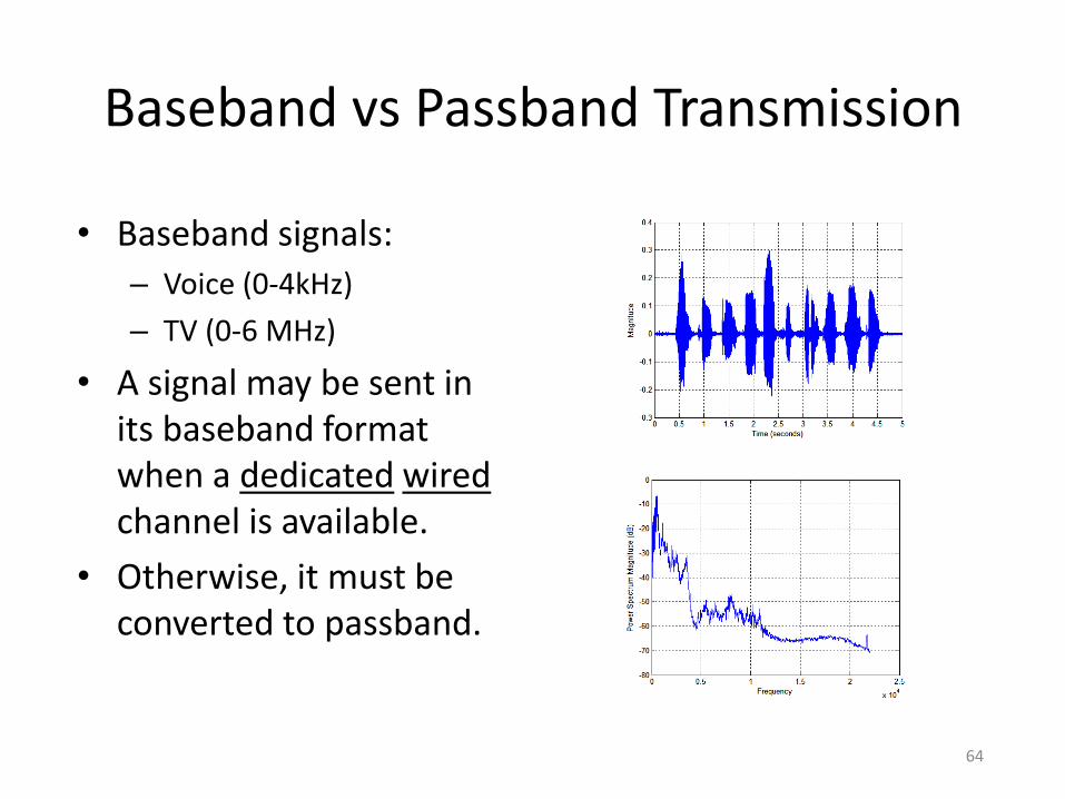
• Baseband signals:
– Voice (0-4kHz)
– TV (0-6 MHz)
• A signal may be sent in its baseband format when a dedicated wired channel is available.
• Otherwise, it must be converted to passband.
64
Types of Amplitude Modulation (AM)
• Double Sideband with carrier (we will call it AM): This is the most widely used type of AM modulation. In fact, all radio channels in the AM band use this type of modulation.
• Double Sideband Suppressed Carrier (DSBSC): This is the same as the AM modulation above but without the carrier.
• Single Sideband (SSB): In this modulation, only half of the signal of the DSBSC is used.
• Vestigial Sideband (VSB): This is a modification of the SSB to ease the generation and reception of the signal.
65
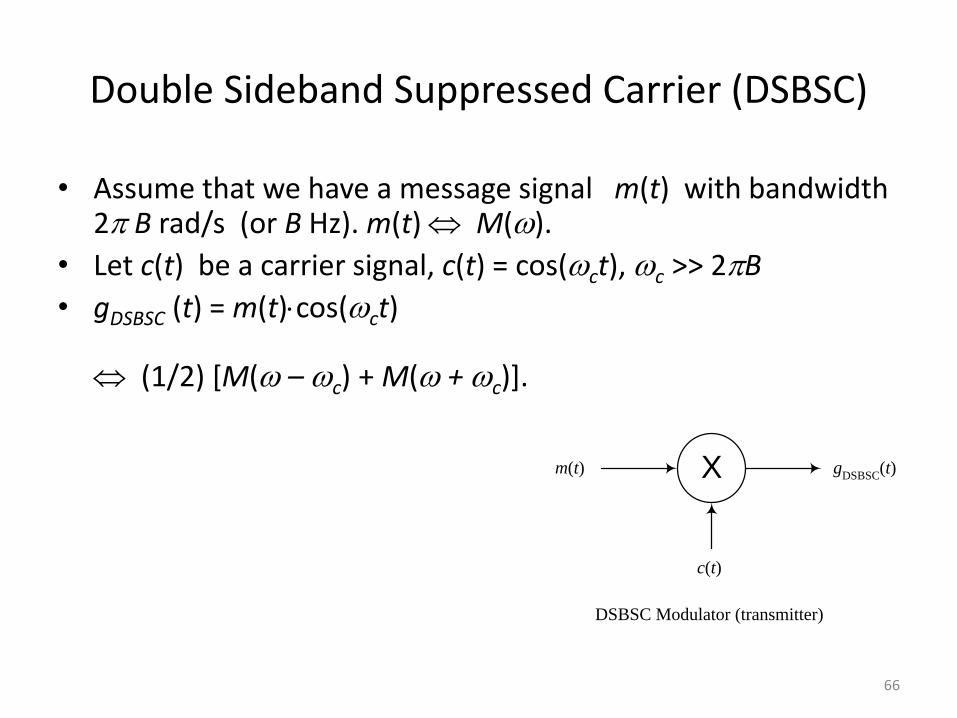
Double Sideband Suppressed Carrier (DSBSC)
• Assume that we have a message signal m(t) with bandwidth 2 B rad/s (or B Hz). m(t) M().
• Let c(t) be a carrier signal, c(t) = cos(ct), c >> 2B
• gDSBSC (t) = m(t)cos(ct) (1/2) [M( – c) + M( + c)].
Xm(t)
c(t)
gDSBSC
(t)
DSBSC Modulator (transmitter)
66
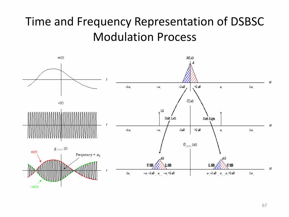
Time and Frequency Representation of DSBSC Modulation Process
67
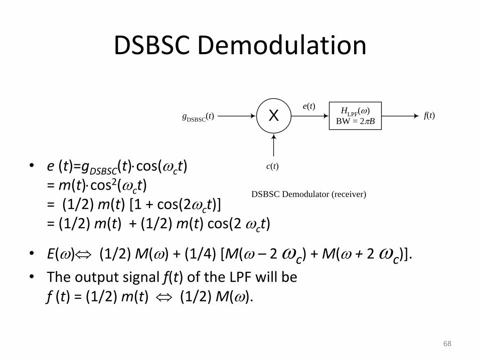
DSBSC Demodulation
• e (t)=gDSBSC(t)cos(ct) = m(t)cos2(ct) = (1/2) m(t) [1 + cos(2ct)] = (1/2) m(t) + (1/2) m(t) cos(2 ct)
• E() (1/2) M() + (1/4) [M( – 2 c) + M( + 2 c)].
• The output signal f(t) of the LPF will be f (t) = (1/2) m(t) (1/2) M().
X
c(t)
gDSBSC
(t)e(t)
HLPF
()
BW = 2Bf(t)
DSBSC Demodulator (receiver)
68
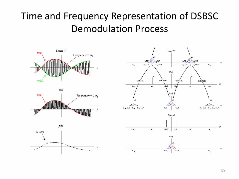
Time and Frequency Representation of DSBSC Demodulation Process
69
Modulator Circuits
• Basically we are after multiplying a signal with a carrier.
• There are three realizations of this operation:
– Multiplier Circuits
– Non-Linear Circuits
– Switching Circuits
70
Non-Linear Devices (NLD)
• A NLD is a device whose input-output relation is non-linear. One such example is the diode (iD=evD/vT).
• The output of a NLD can be expressed as a power series of the input, that is y(t) = ax(t) + bx2(t) + cx3(t) + …
• When x(t) << 1, the higher powers can be neglected, and the output can be approximated by the first two terms.
• When the input x(t) is the sum of two signal, m(t)+c(t), x2(t) will have the product term m(t)c(t)
71
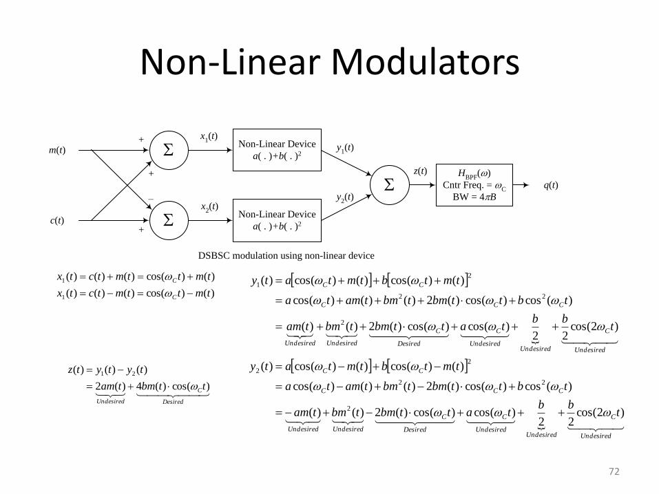
Non-Linear Modulators
+ z(t)
y1(t)
y2(t)
+
–
DSBSC modulation using non-linear device
Non-Linear Device
a( . )+b( . )2
HBPF
()
Cntr Freq. = C
BW = 4B
m(t)
c(t)
x1(t)
q(t)
Non-Linear Device
a( . )+b( . )2
x2(t)
+
Undesired
C
UndesiredUndesired
C
Desired
C
UndesiredUndesired
CCC
CC
Undesired
C
UndesiredUndesired
C
Desired
C
UndesiredUndesired
CCC
CC
tbb
tattbmtbmtam
tbttbmtbmtamta
tmtbtmtaty
tbb
tattbmtbmtam
tbttbmtbmtamta
tmtbtmtaty
)2cos(22
)cos()cos()(2)()(
)(cos)cos()(2)()()cos(
)()cos()()cos()(
)2cos(22
)cos()cos()(2)()(
)(cos)cos()(2)()()cos(
)()cos()()cos()(
2
22
2
2
2
22
2
1
)()cos()()()(
)()cos()()()(
1
1
tmttmtctx
tmttmtctx
C
C
Desired
C
Undesired
ttbmtam
tytytz
)cos()(4)(2
)()()( 21
72
Switching Modulators
• Any periodic function can be expressed as a series of cosines (Fourier Series).
• The information signal, m(t), can therefore be, equivalently, multiplied by any periodic function, and followed by BPF.
• Let this periodic function be a train of pulses.
• Multiplication by a train of pulses can be realized by simple switching.
73
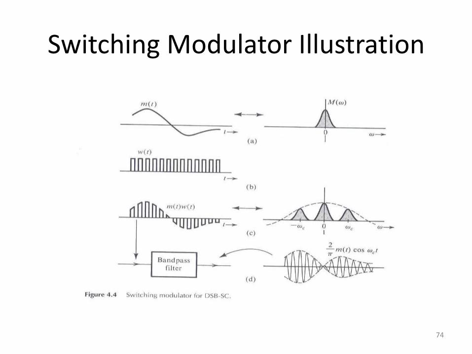
Switching Modulator Illustration
74
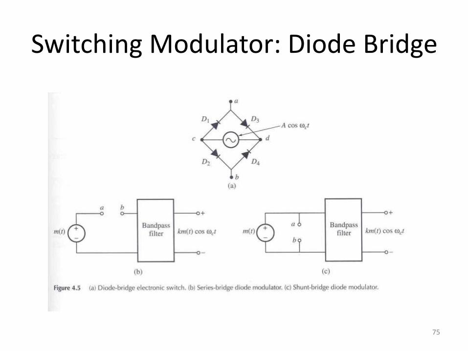
Switching Modulator: Diode Bridge
75
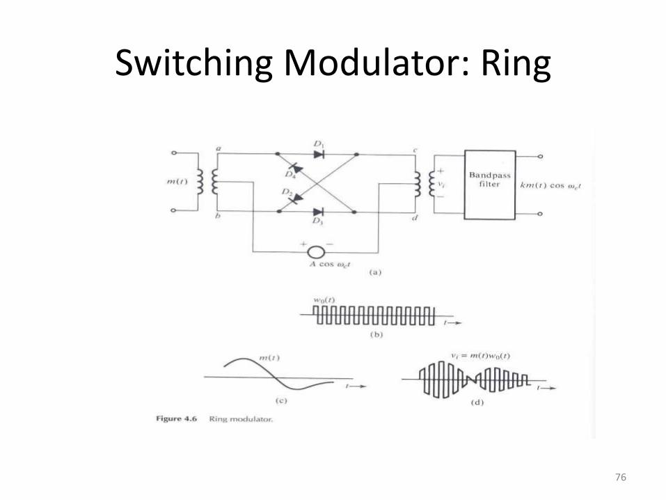
Switching Modulator: Ring
76
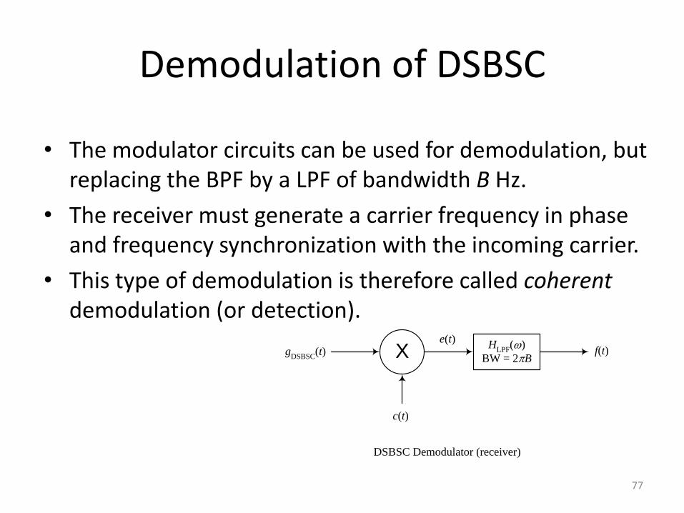
Demodulation of DSBSC
• The modulator circuits can be used for demodulation, but replacing the BPF by a LPF of bandwidth B Hz.
• The receiver must generate a carrier frequency in phase and frequency synchronization with the incoming carrier.
• This type of demodulation is therefore called coherent demodulation (or detection).
X
c(t)
gDSBSC
(t)e(t)
HLPF
()
BW = 2Bf(t)
DSBSC Demodulator (receiver)
77
From DSBSC to DSBWC (AM)
• Carrier recovery circuits, which are required for the operation of coherent demodulation, are sophisticated and could be quite costly.
• If we can let m(t) be the envelope of the modulated signal, then a much simpler circuit, the envelope detector, can be used for demodulation (non-coherent demodulation).
• How can we make m(t) be the envelope of the modulated signal?
78
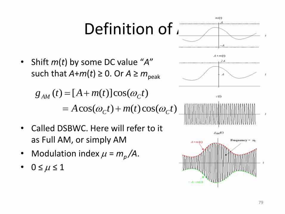
Definition of AM
• Shift m(t) by some DC value “A” such that A+m(t) ≥ 0. Or A ≥ mpeak
• Called DSBWC. Here will refer to it as Full AM, or simply AM
• Modulation index m = mp /A.
• 0 ≤ m ≤ 1
)cos()()cos(
)cos()]([)(
ttmtA
ttmAtg
CC
CAM
79
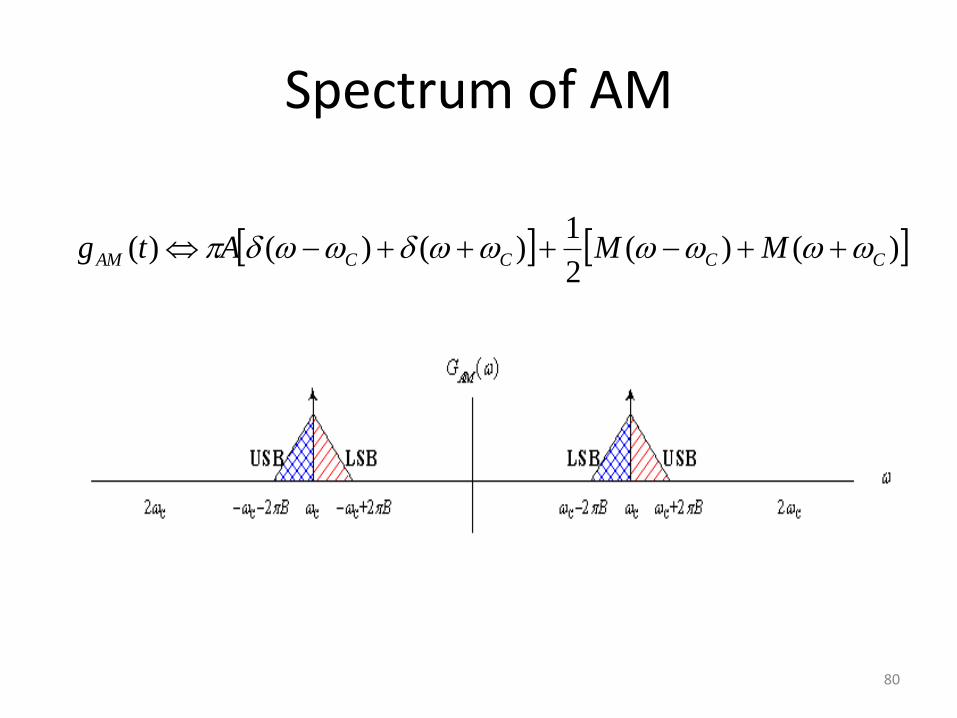
Spectrum of AM
)()(2
1)()()( CCCCAM MMAtg
80
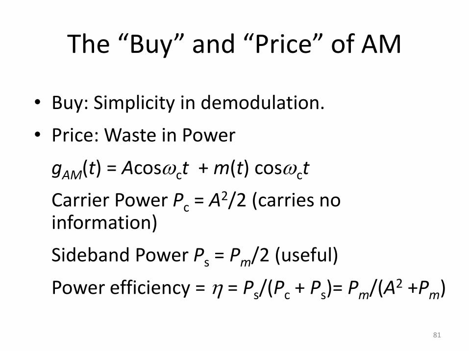
The “Buy” and “Price” of AM
• Buy: Simplicity in demodulation.
• Price: Waste in Power
gAM(t) = Acosct + m(t) cosct
Carrier Power Pc = A2/2 (carries no information)
Sideband Power Ps = Pm/2 (useful)
Power efficiency = h = Ps/(Pc + Ps)= Pm/(A2 +Pm)
81
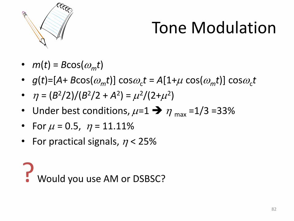
Tone Modulation
• m(t) = Bcos(mt)
• g(t)=[A+ Bcos(mt)] cosct = A[1+m cos(mt)] cosct
• h = (B2/2)/(B2/2 + A2) = m2/(2+m2)
• Under best conditions, m=1 h max =1/3 =33%
• For m = 0.5, h = 11.11%
• For practical signals, h < 25%
? Would you use AM or DSBSC?
82
Generation of AM
• AM signals can be generated by any DSBSC modulator, by using A+m(t) as input instead of m(t).
• In fact, the presence of the carrier term can make it even simpler. We can use it for switching instead of generating a local carrier.
• The switching action can be made by a single diode instead of a diode bridge.
83
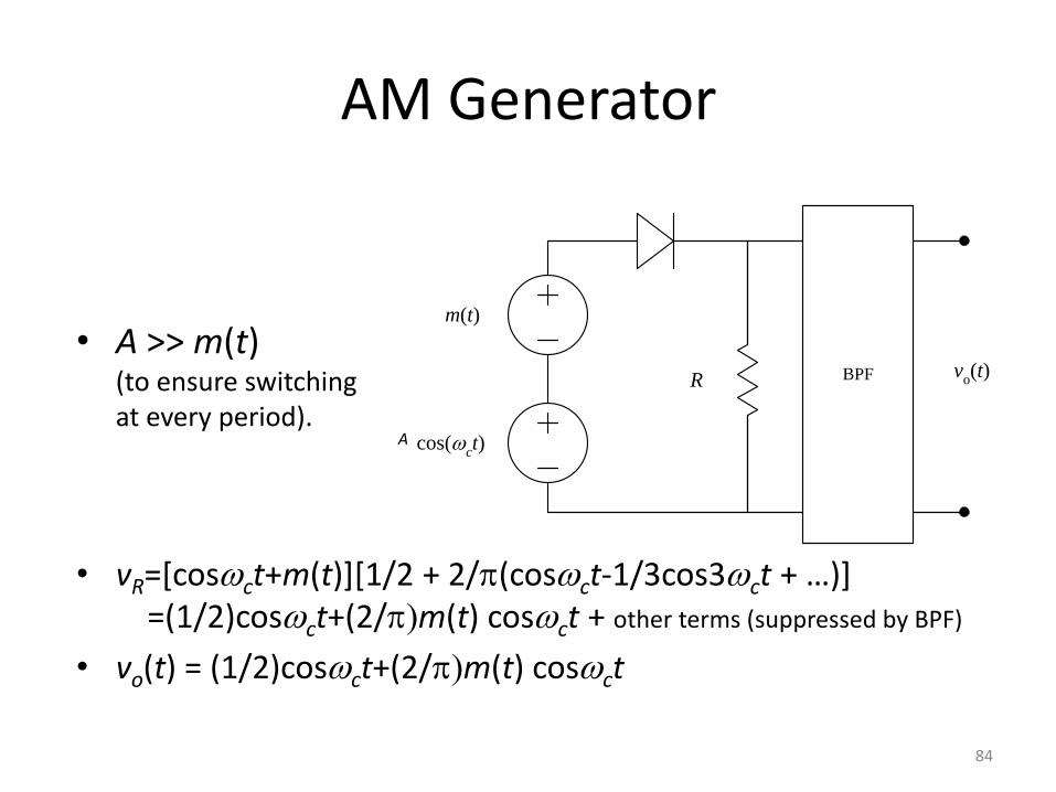
AM Generator
• A >> m(t) (to ensure switching at every period).
• vR=[cosct+m(t)][1/2 + 2/(cosct-1/3cos3ct + …)+ =(1/2)cosct+(2/m(t) cosct + other terms (suppressed by BPF)
• vo(t) = (1/2)cosct+(2/m(t) cosct
cos(ct)
m(t)
R BPF vo(t)
A
84
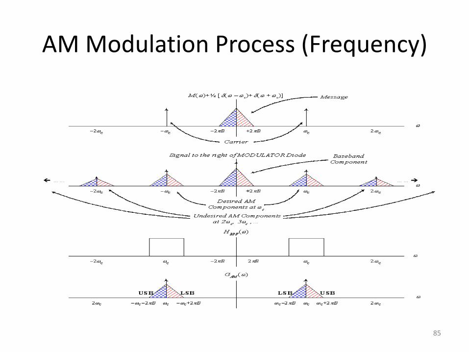
AM Modulation Process (Frequency)
85
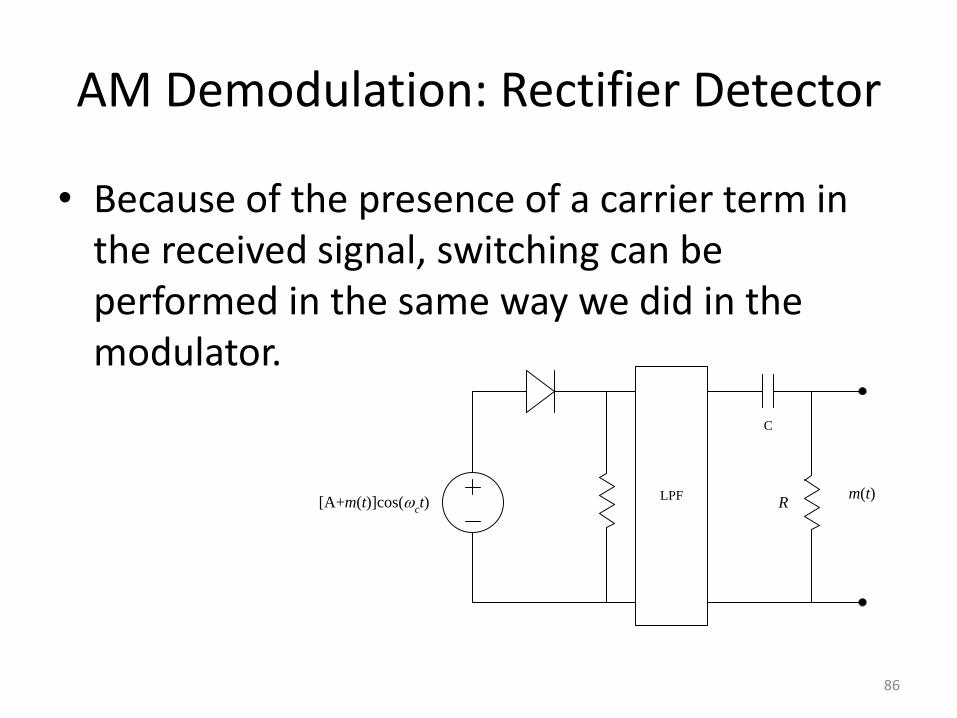
AM Demodulation: Rectifier Detector
• Because of the presence of a carrier term in the received signal, switching can be performed in the same way we did in the modulator.
[A+m(t)]cos(ct)
LPF m(t)
C
R
86
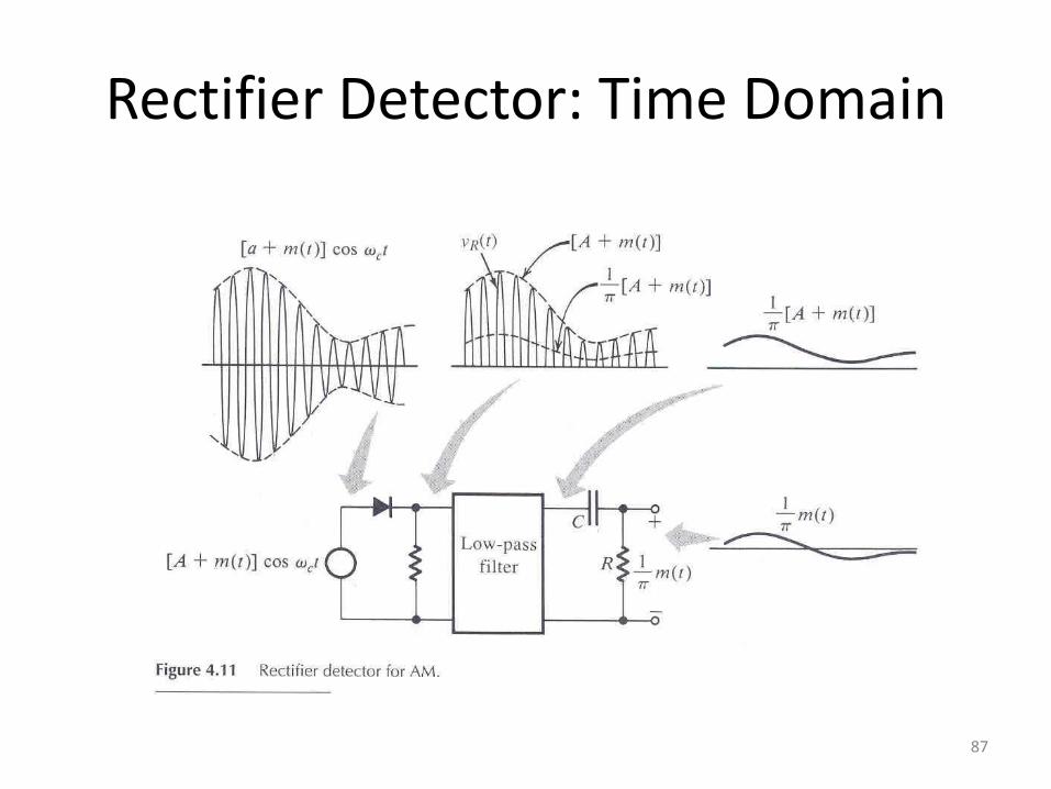
Rectifier Detector: Time Domain
87
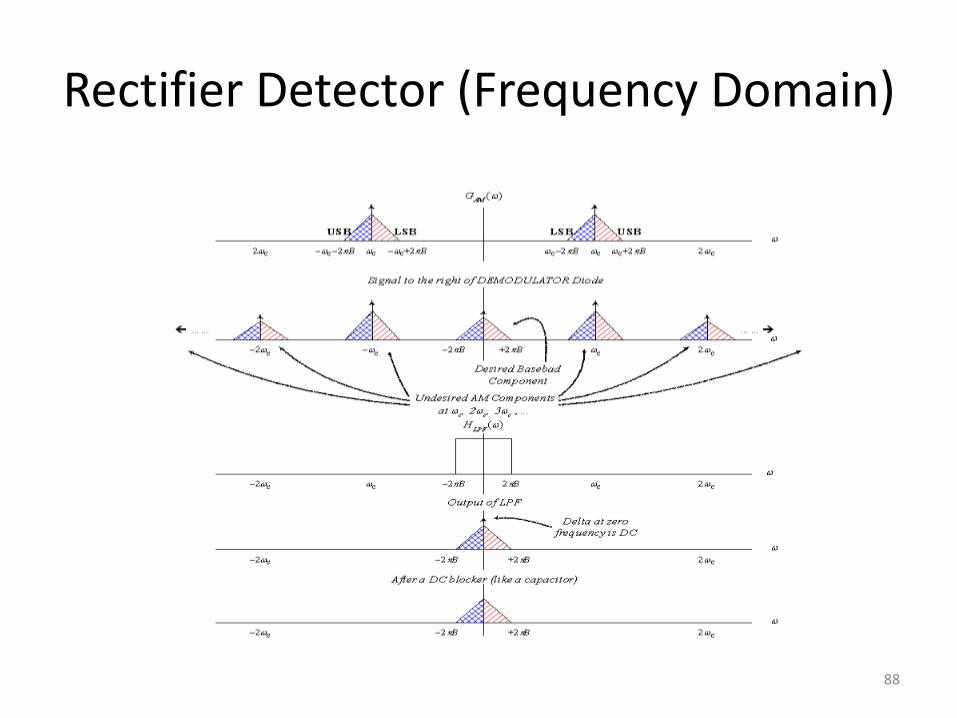
Rectifier Detector (Frequency Domain)
88
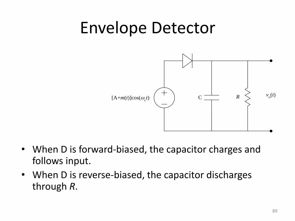
Envelope Detector
• When D is forward-biased, the capacitor charges and follows input.
• When D is reverse-biased, the capacitor discharges through R.
[A+m(t)]cos(ct)
vo(t)RC
89
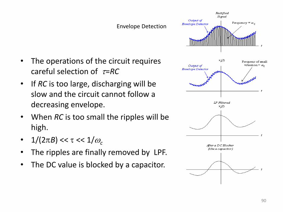
Envelope Detection
• The operations of the circuit requires careful selection of t=RC
• If RC is too large, discharging will be slow and the circuit cannot follow a decreasing envelope.
• When RC is too small the ripples will be high.
• 1/(2B) << t << 1/c
• The ripples are finally removed by LPF.
• The DC value is blocked by a capacitor.
90
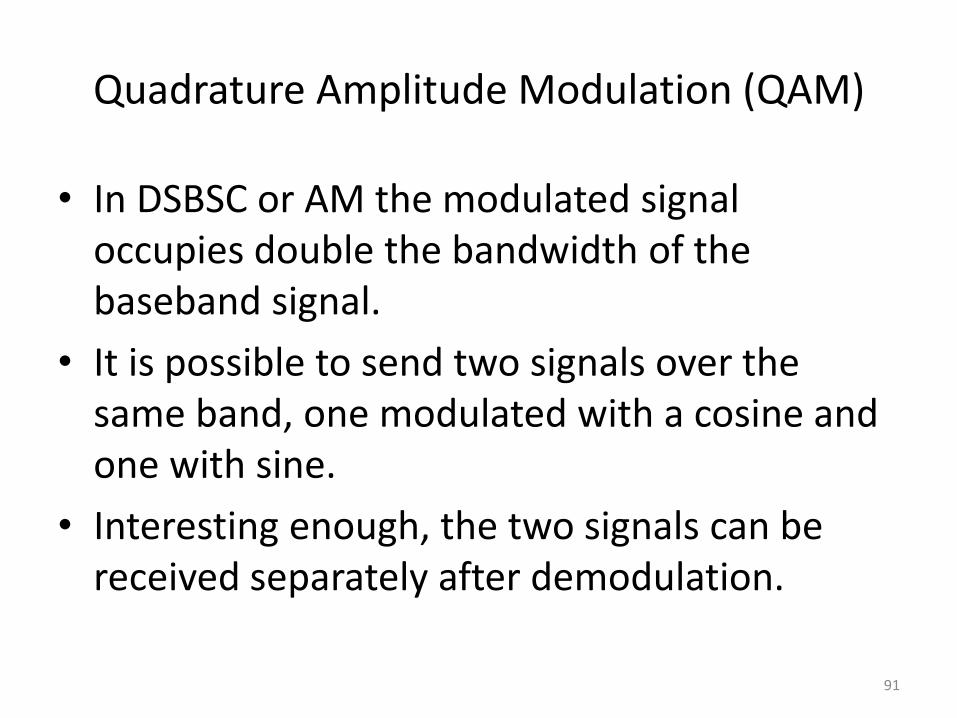
Quadrature Amplitude Modulation (QAM)
• In DSBSC or AM the modulated signal occupies double the bandwidth of the baseband signal.
• It is possible to send two signals over the same band, one modulated with a cosine and one with sine.
• Interesting enough, the two signals can be received separately after demodulation.
91
m1(t)cos(
ct)
HLPF
()
BW = 2BXm1(t)
cos(ct)
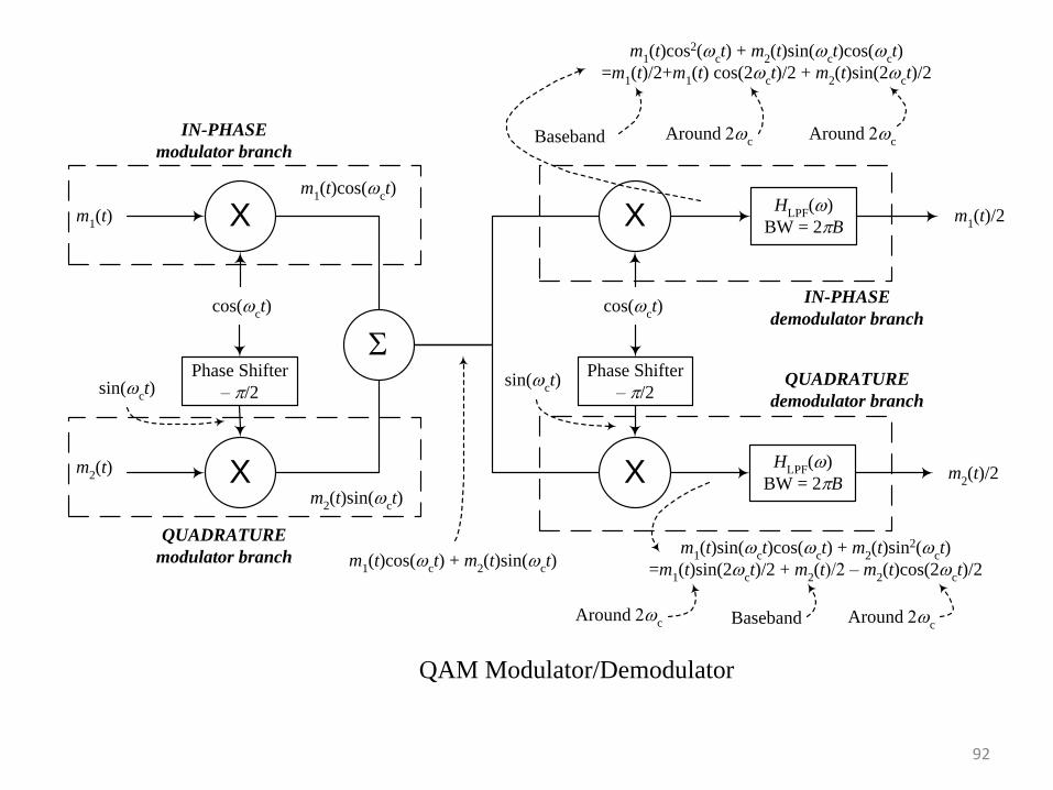
QAM Modulator/Demodulator
m2(t)sin(
ct)
Xm2(t)
sin(ct)
Phase Shifter
– /2
m1(t)cos(
ct) + m
2(t)sin(
ct)
X m1(t)/2
cos(ct)
X m2(t)/2
sin(ct)
Phase Shifter
– /2
m1(t)cos2(
ct) + m
2(t)sin(
ct)cos(
ct)
=m1(t)/2+m
1(t) cos(2
ct)/2 + m
2(t)sin(2
ct)/2
HLPF
()
BW = 2B
Baseband Around c
Around c
m1(t)sin(
ct)cos(
ct) + m
2(t)sin2(
ct)
=m1(t)sin(2
ct)/2 + m
2(t)/2 – m
2(t)cos(2
ct)/2
BasebandAround c Around
c
QUADRATURE
modulator branch
IN-PHASE
modulator branch
QUADRATURE
demodulator branch
IN-PHASE
demodulator branch
92
m1(t)cos(
ct)
HLPF
()
BW = 2BXm1(t)
cos(ct)
QAM Modulator/Demodulator with Demodulator Carrier Phase and/or Frequency Error
m2(t)sin(
ct)
Xm2(t)
sin(ct)
Phase Shifter
– /2
m1(t)cos(
ct) + m
2(t)sin(
ct)
X (1/2)[m1(t)cos(t+) – m
2(t)sin(t+)]
cos[(c+t+
X (1/2)[m1(t)sin(t+) + m
2(t)cos(t+)]
sin[(c+t+
Phase Shifter
– /2
m1(t)cos(
ct)cos[(
c+t+ + m
2(t)sin(
ct)cos[(
c+t+
=(1/2)[m1(t)cos(t+) + m
1(t) cos(2
ct+t+) – m
2(t)sin(t+) + m
2(t)sin(2
ct+t+)]
HLPF
()
BW = 2B
Baseband Around c Around
c
BasebandAround c Around
c
Baseband
m1(t)cos(
ct)sin[(
c+t+ + m
2(t)sin(
ct)sin[(
c+t+
=(1/2)[m1(t)sin(t+) + m
1(t) sin(2
ct+t+) + m
2(t)cos(t+) – m
2(t)cos(2
ct+t+)]
Baseband
93
Single-Side Band (SSB) Modulation
• DSBSC (as well as AM) occupies double the bandwidth of the baseband signal, although the two sides carry the same information.
• Why not send only one side, the upper or the lower?
• Modulation: similar to DSBSC. Only change the settings of the BPF (center frequency, bandwidth).
• Demodulation: similar to DSBSC (coherent)
94
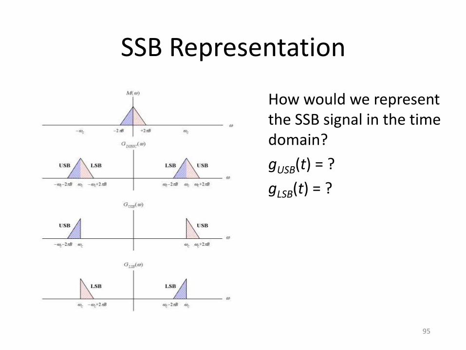
SSB Representation
How would we represent the SSB signal in the time domain?
gUSB(t) = ?
gLSB(t) = ?
95
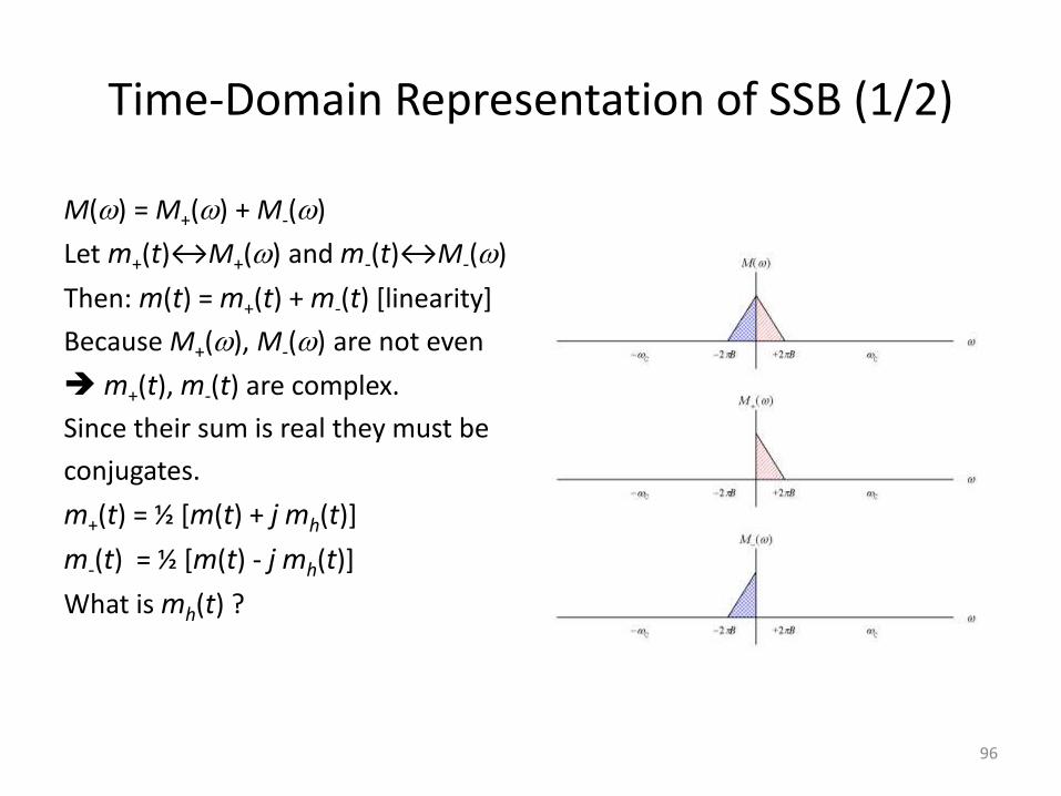
Time-Domain Representation of SSB (1/2)
M() = M+() + M-()
Let m+(t)↔M+() and m-(t)↔M-()
Then: m(t) = m+(t) + m-(t) [linearity]
Because M+(), M-() are not even
m+(t), m-(t) are complex.
Since their sum is real they must be
conjugates.
m+(t) = ½ [m(t) + j mh(t)]
m-(t) = ½ [m(t) - j mh(t)]
What is mh(t) ?
96
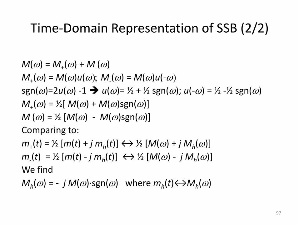
Time-Domain Representation of SSB (2/2)
M() = M+() + M-()
M+() = M()u(; M-() = M()u(-
sgn()=2u() -1 u()= ½ + ½ sgn(); u(-) = ½ -½ sgn()
M+() = ½[ M() + M()sgn()]
M-() = ½ [M() - M()sgn()]
Comparing to:
m+(t) = ½ [m(t) + j mh(t)+ ↔ ½ *M() + j Mh()]
m-(t) = ½ [m(t) - j mh(t)+ ↔ ½ *M() - j Mh()]
We find
Mh() = - j M()∙sgn() where mh(t)↔Mh()
97
Hilbert Transform
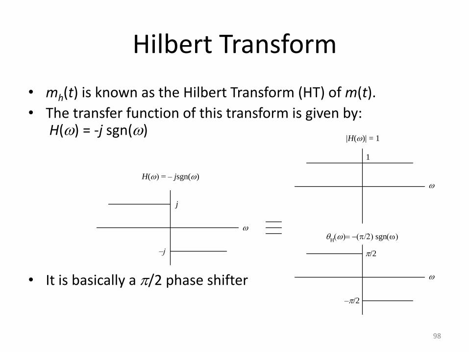
• mh(t) is known as the Hilbert Transform (HT) of m(t).
• The transfer function of this transform is given by: H() = -j sgn()
• It is basically a /2 phase shifter
H() = – jsgn()
j
–j
|H()| = 1
1
/2
–/2
sgn
98
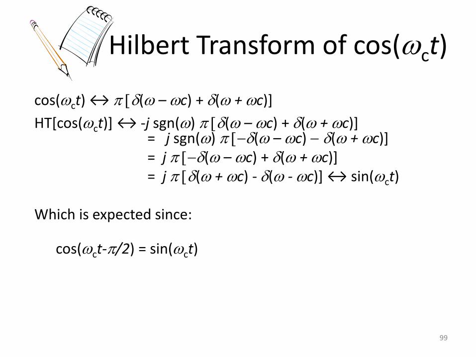
Hilbert Transform of cos(ct)
cos(ct) ↔ ( – c) + ( + c)]
HT[cos(ct)+ ↔ -j sgn() ( – c) + ( + c)] = j sgn() ( – c) ( + c)]
= j ( – c) + ( + c)] = j ( + c) - ( - c)+ ↔ sin(ct) Which is expected since:
cos(ct-/2) = sin(ct)
99
Time-Domain Operation for Hilbert Transformation
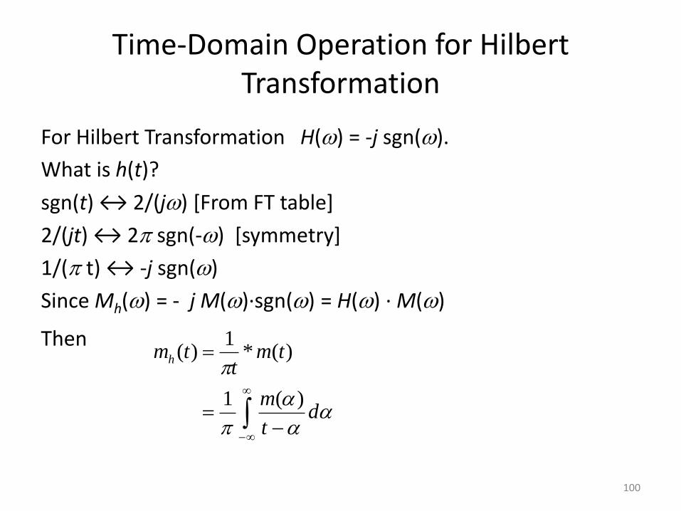
For Hilbert Transformation H() = -j sgn().
What is h(t)?
sgn(t) ↔ 2/(j) [From FT table]
2/(jt) ↔ 2 sgn(-) [symmetry]
1/( t) ↔ -j sgn()
Since Mh() = - j M()∙sgn() = H() ∙ M()
Then
dt
m
tmt
tmh
)(1
)(*1
)(
100
)sin()()cos()(
)(2
1)(
2
1
)(2
1)(
2
1)(
)sin()()cos()(
)(2
1)(
2
1
)(2
1)(
2
1)(
ttmttm
etjmetm
etjmetmtg
ttmttm
etjmetm
etjmetmtg
ChC
tj
h
tj
tj
h
tj
LSB
ChC
tj
h
tj
tj
h
tj
USB
CC
CC
CC
CC
)()()(
)()()(
CCLSB
CCUSB
MMG
MMG
tjtj
LSB
tjtj
USB
CC
CC
etmetmtg
etmetmtg
)()()(
)()()(
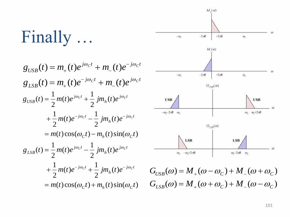
Finally …
101
Generation of SSB
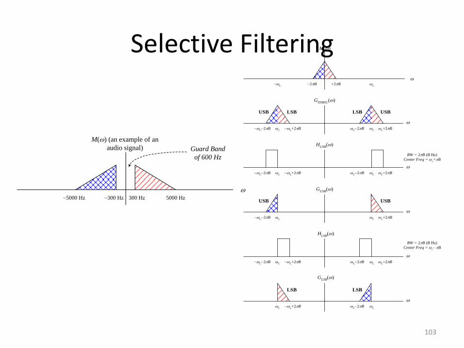
• Selective Filtering Method Realization based on spectrum analysis
• Phase-Shift Method Realization based on time-domain expression of the modulated signal
102
Selective Filtering
GDSBSC
()
C+2B
C2B
C
C
C+2B
C2B
USBLSBLSBUSB
M()
+2B
2B
C
C
GUSB
()
C+2B
C
C
C2B
USBUSB
GLSB
()
C2B
C
C
C+2B
LSBLSB
HUSB
()
C+2B
C2B
C
C
C+2B
C2B
HLSB
()
C+2B
C2B
C
C
C+2B
C2B
BW = 2B (B Hz)
Center Freq = c+B
BW = 2B (B Hz)
Center Freq = c– B
M() (an example of an
audio signal)
5000 Hz 300 Hz 300 Hz 5000 Hz
Guard Band
of 600 Hz
103
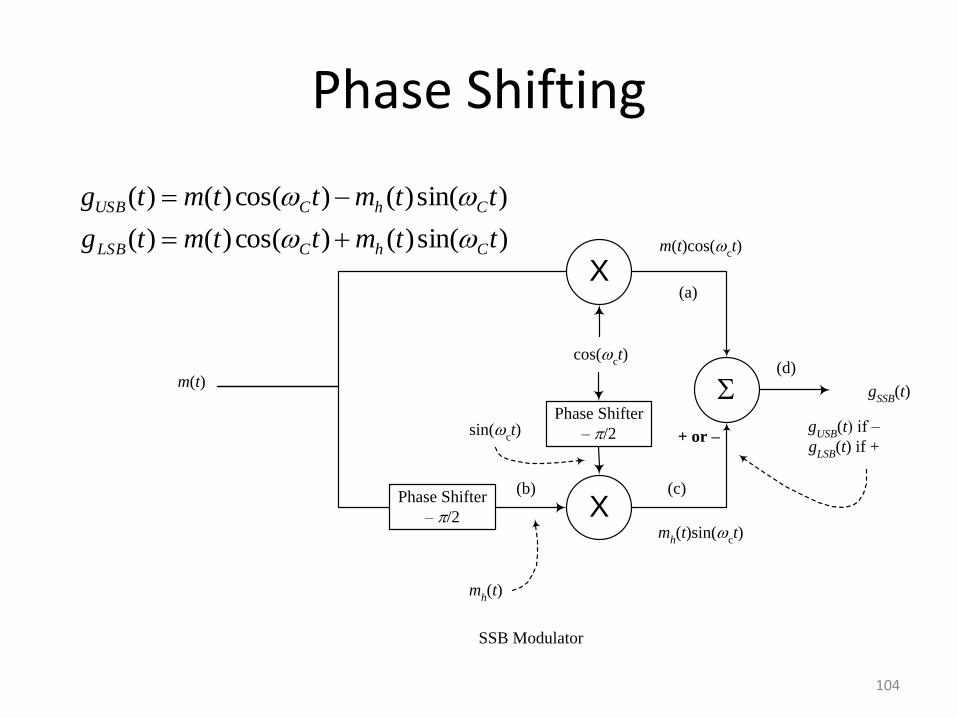
Phase Shifting
X
cos(ct)
SSB Modulator
X
sin(ct)
Phase Shifter
– /2
Phase Shifter
– /2
m(t)
mh(t)
mh(t)sin(
ct)
m(t)cos(ct)
gSSB
(t)
gUSB
(t) if –
gLSB
(t) if ++ or –
(a)
(b) (c)
(d)
)sin()()cos()()(
)sin()()cos()()(
ttmttmtg
ttmttmtg
ChCLSB
ChCUSB
104
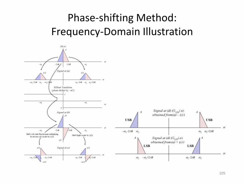
Phase-shifting Method: Frequency-Domain Illustration
105
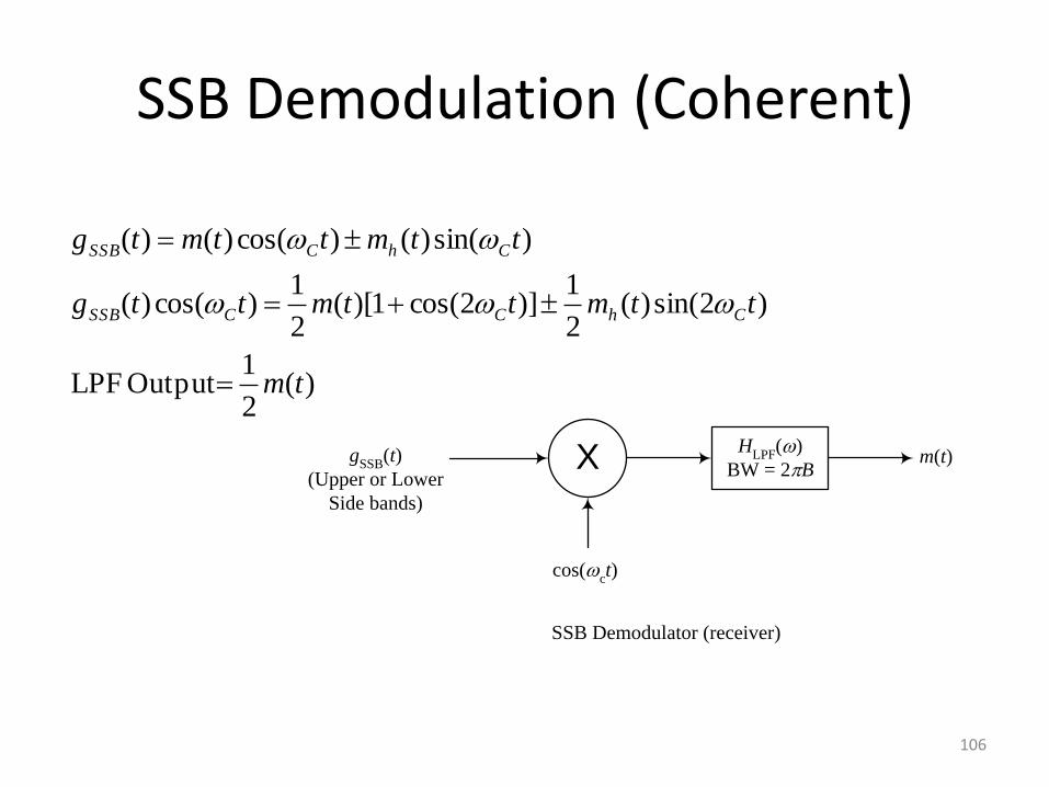
SSB Demodulation (Coherent)
X
cos(ct)
gSSB
(t)
(Upper or Lower
Side bands)
HLPF
()
BW = 2Bm(t)
SSB Demodulator (receiver)
)(2
1 Output LPF
)2sin()(2
1)]2cos(1)[(
2
1)cos()(
)sin()()cos()()(
tm
ttmttmttg
ttmttmtg
ChCCSSB
ChCSSB
106
FDM in Telephony
• FDM is done in stages – Reduce number of carrier frequencies
– More practical realization of filters
• Group: 12 voice channels 4 kHz = 48 kHz occupy the band 60-108 kHz
• Supergroup: 5 groups 48 kHz = 240 kHz occupy the band 312-552
• Mastergroup: 10 S-G 240 kHz = 2400 kHz occupy the band 564-3084 kHz
107
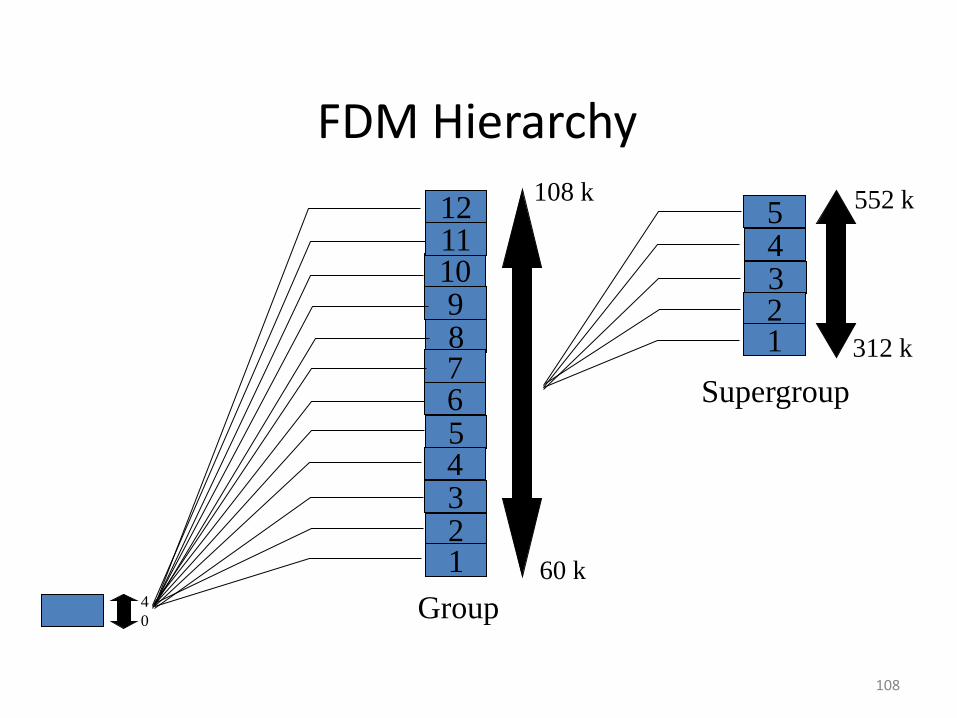
FDM Hierarchy
4
0
5 4 3 2 1
10 9 8 7 6
5 4 3 2 1
11 12
60 k
108 k
312 k
552 k
Group
Supergroup
108
Vestigial Side Band Modulation (VSB)
• What if we want to generate SSB using selective filtering but there is no guard band between the two sides? We will filter-in a vestige of the other band.
• Can we still recover our message, without distortion, after demodulation? Yes. If we use a proper LPF.
109
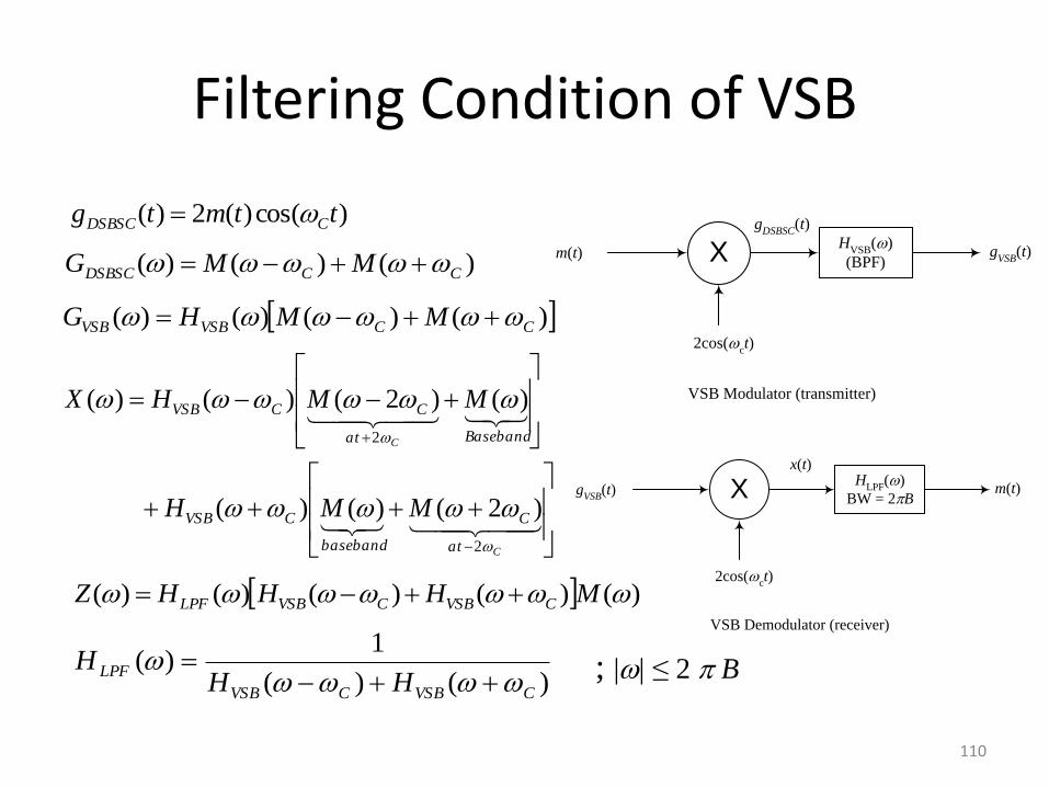
Filtering Condition of VSB
X
2cos(ct)
m(t)H
VSB()
(BPF)g
VSB(t)
VSB Modulator (transmitter)
gDSBSC
(t)
X
2cos(ct)
gVSB
(t)H
LPF()
BW = 2Bm(t)
VSB Demodulator (receiver)
x(t)
)cos()(2)( ttmtg CDSBSC
)()()( CCDSBSC MMG
)()()()( CCVSBVSB MMHG
C
C
at
C
baseband
CVSB
Basebandat
CCVSB
MMH
MMHX
2
2
)2()()(
)()2()()(
)()()()()( MHHHZ CVSBCVSBLPF
)()(
1)(
CVSBCVSB
LPFHH
H
; || ≤ 2 B
110
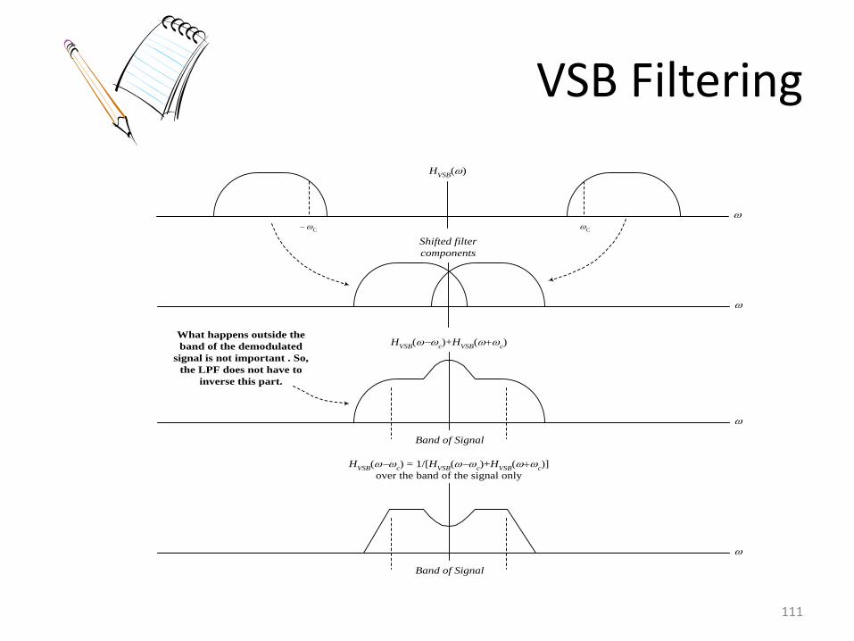
VSB Filtering
HVSB
()
C
C
HVSB
(c)+H
VSB(
c)
Shifted filter
components
Band of Signal
HVSB
(c) = 1/[H
VSB(
c)+H
VSB(
c)]
over the band of the signal only
Band of Signal
What happens outside the
band of the demodulated
signal is not important . So,
the LPF does not have to
inverse this part.
111
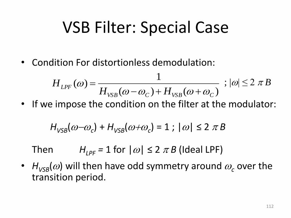
VSB Filter: Special Case
• Condition For distortionless demodulation:
• If we impose the condition on the filter at the modulator: HVSB(c) + HVSB(c) = 1 ; || ≤ 2 B Then HLPF = 1 for || ≤ 2 B (Ideal LPF)
• HVSB() will then have odd symmetry around c over the transition period.
)()(
1)(
CVSBCVSB
LPFHH
H
; || ≤ 2 B
112
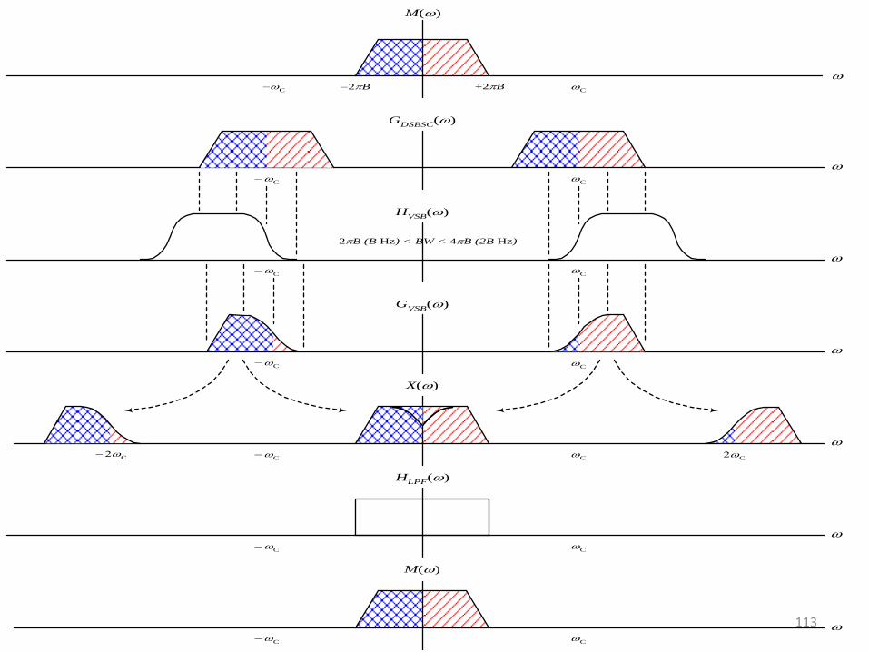
GDSBSC
()
C
C
M()
+2B
2B
C
C
HVSB
()
2B (B Hz) < BW < 4B (2B Hz)
C
C
GVSB
()
C
C
X()
C
C
C
M()
C
C
HLPF
()
C
C
C
113
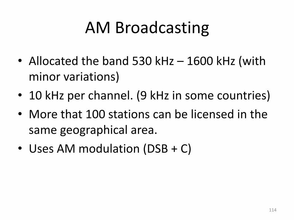
AM Broadcasting
• Allocated the band 530 kHz – 1600 kHz (with minor variations)
• 10 kHz per channel. (9 kHz in some countries)
• More that 100 stations can be licensed in the same geographical area.
• Uses AM modulation (DSB + C)
114
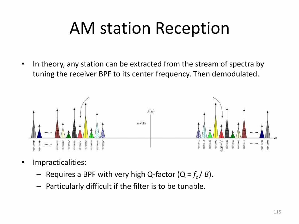
AM station Reception
• In theory, any station can be extracted from the stream of spectra by tuning the receiver BPF to its center frequency. Then demodulated.
• Impracticalities:
– Requires a BPF with very high Q-factor (Q = fc / B).
– Particularly difficult if the filter is to be tunable.
115
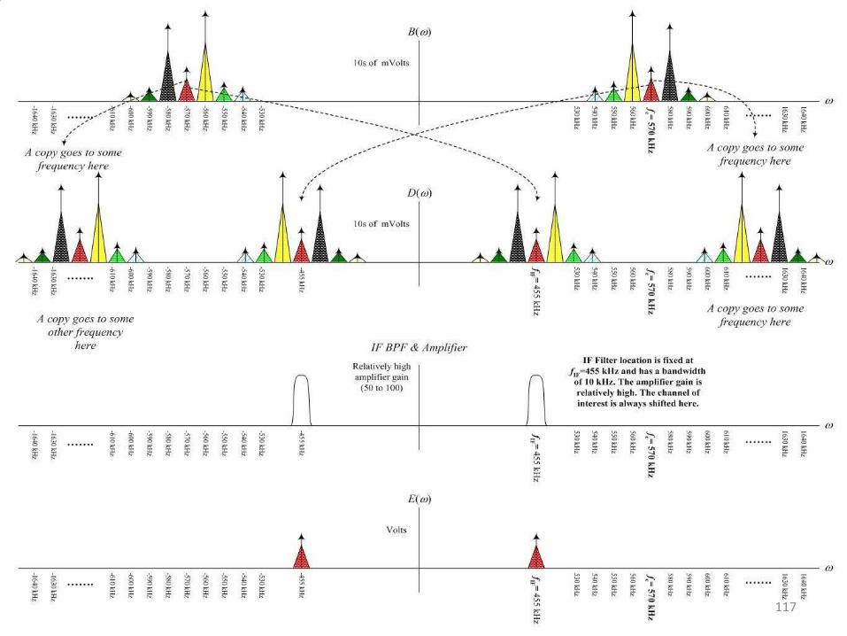
Solution: Superheterodyne receiver
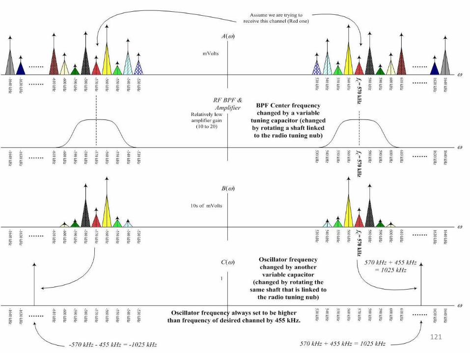
• Step 1: Frequency Translation from RF to IF Shift the desired station to another fixed pass band (called Intermediate Frequency IF = 455 kHz)
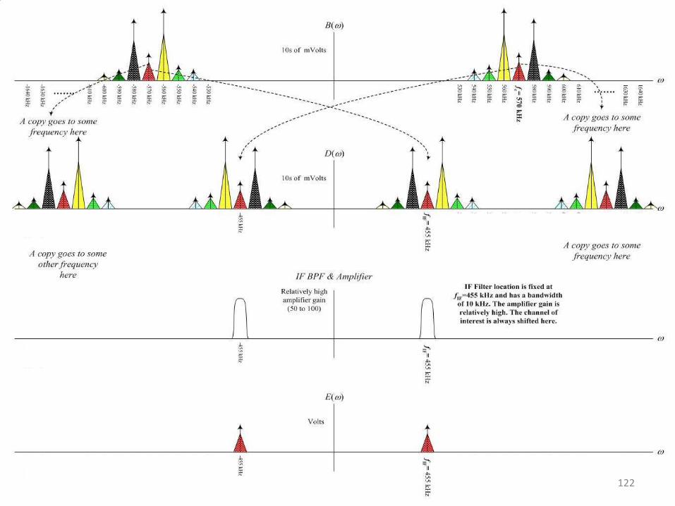
• Step 2: Bandpass Filtering at IF Build a good BPF around IF to extract the desired station. It is more practical now, because IF is relatively low (reasonable Q) and the filter is not tunable.
• Step 3: Demodulation Use Envelope Detector
116
117

The Local Oscillator
• What should be the frequency of the local oscillator used for translation from RF to IF? fLO = fc + fIF (up-conversion)
or fLO = fc fIF (down-conversion)
• Tuning ratio = fLO, max / fLO, min
• Up-Conversion: (1600 + 455) / (530+455) ≈ 2
• Down-Conversion: (1600–455) / (530–455) ≈ 12
• Easier to design oscillator with small tuning ratio.
118
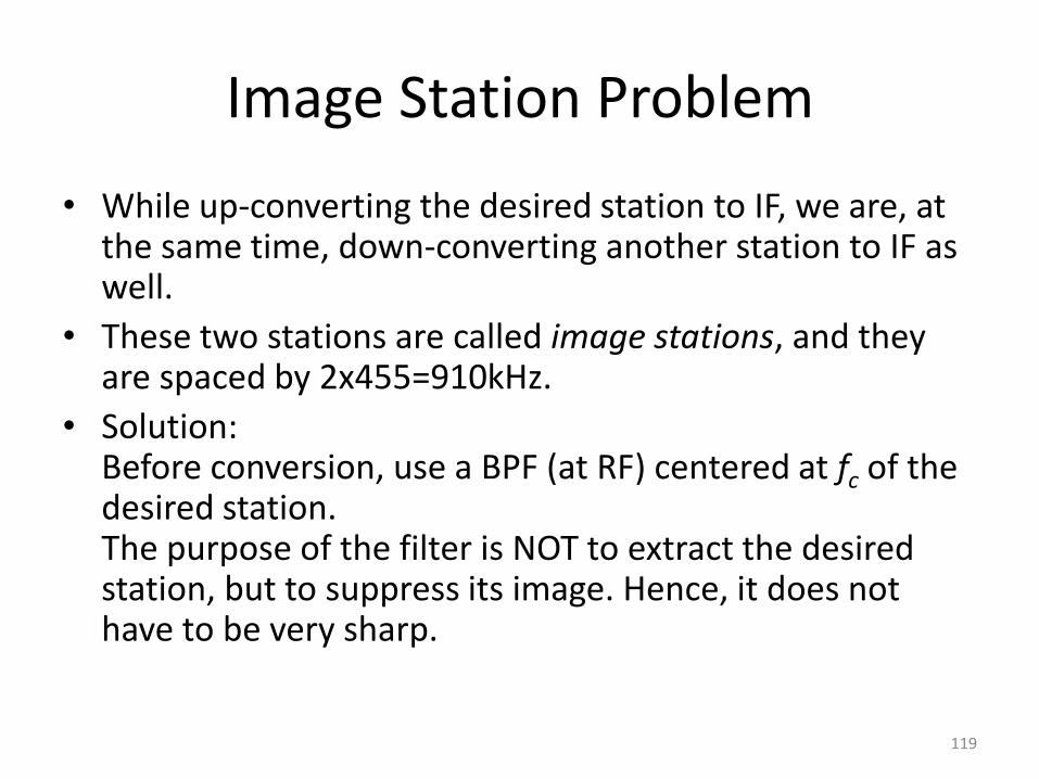
Image Station Problem
• While up-converting the desired station to IF, we are, at the same time, down-converting another station to IF as well.
• These two stations are called image stations, and they are spaced by 2x455=910kHz.
• Solution: Before conversion, use a BPF (at RF) centered at fc of the desired station. The purpose of the filter is NOT to extract the desired station, but to suppress its image. Hence, it does not have to be very sharp.
119
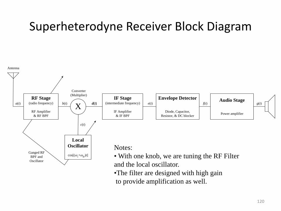
Superheterodyne Receiver Block Diagram
Antenna
IF Stage(intermediate frequency)
IF Amplifier
& IF BPF
X
Converter
(Multiplier)
a(t) b(t) d(t)
c(t)
Envelope Detector
Diode, Capacitor,
Resistor, & DC blocker
Audio Stage
Power amplifier
d(t) e(t) f(t) g(t)
Ganged RF
BPF and
Oscillator
RF Stage(radio frequency)
RF Amplifier
& RF BPF
Local
Oscillator
cos[(c+
IF)t]
Notes:
• With one knob, we are tuning the RF Filter
and the local oscillator.
•The filter are designed with high gain
to provide amplification as well.
120
121
122
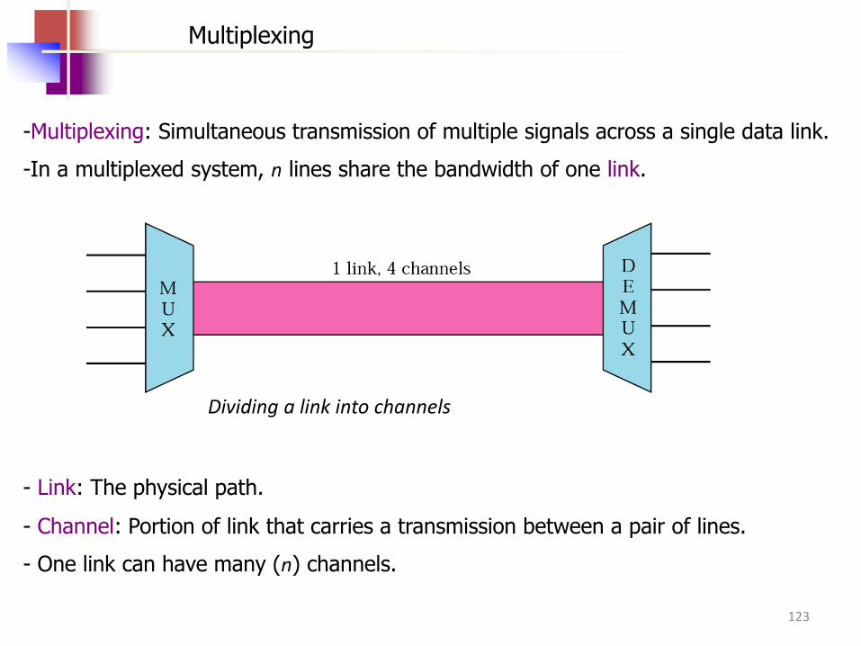
Dividing a link into channels
Multiplexing
-Multiplexing: Simultaneous transmission of multiple signals across a single data link.
-In a multiplexed system, n lines share the bandwidth of one link.
- Link: The physical path.
- Channel: Portion of link that carries a transmission between a pair of lines.
- One link can have many (n) channels.
123
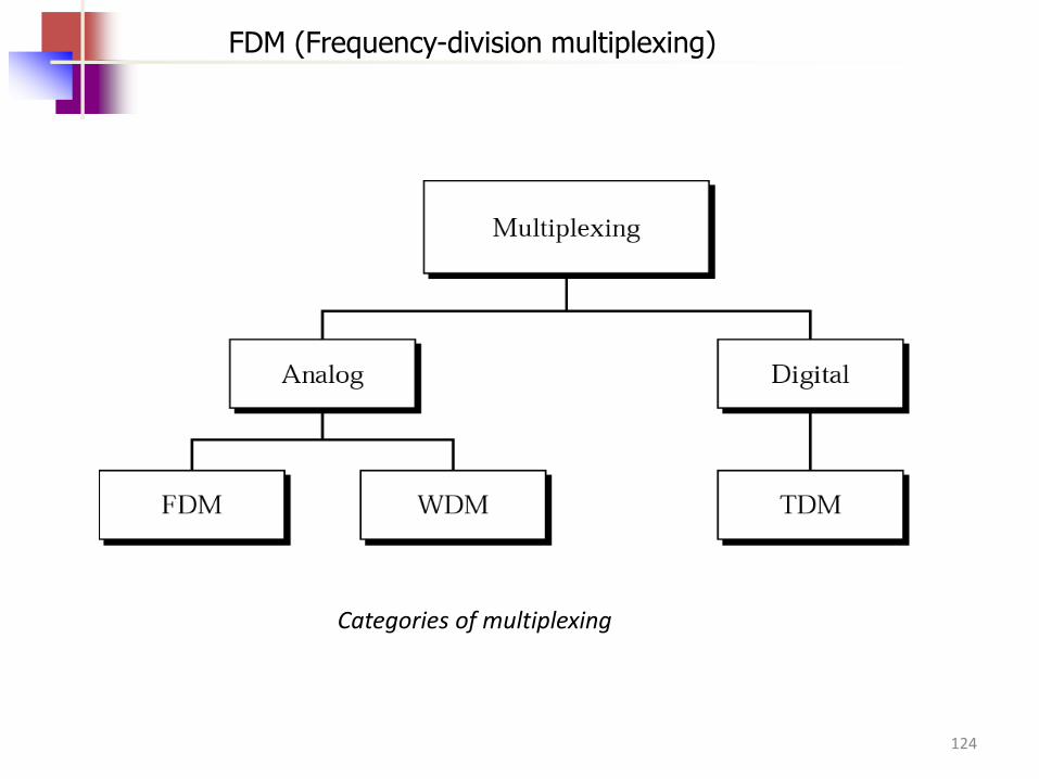
Categories of multiplexing
FDM (Frequency-division multiplexing)
124
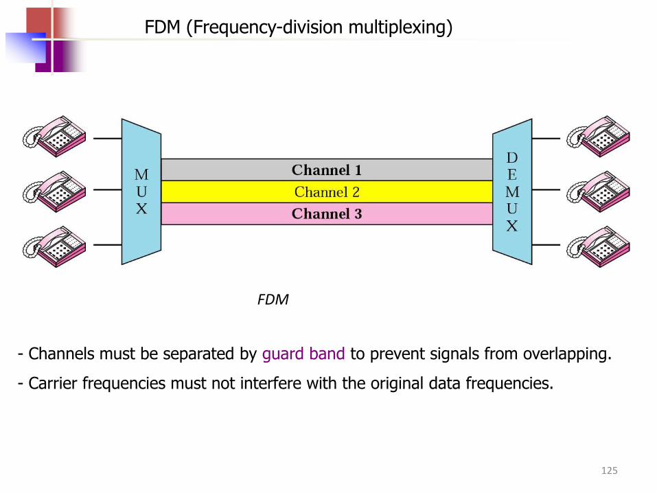
FDM
FDM (Frequency-division multiplexing)
- Channels must be separated by guard band to prevent signals from overlapping.
- Carrier frequencies must not interfere with the original data frequencies.
125
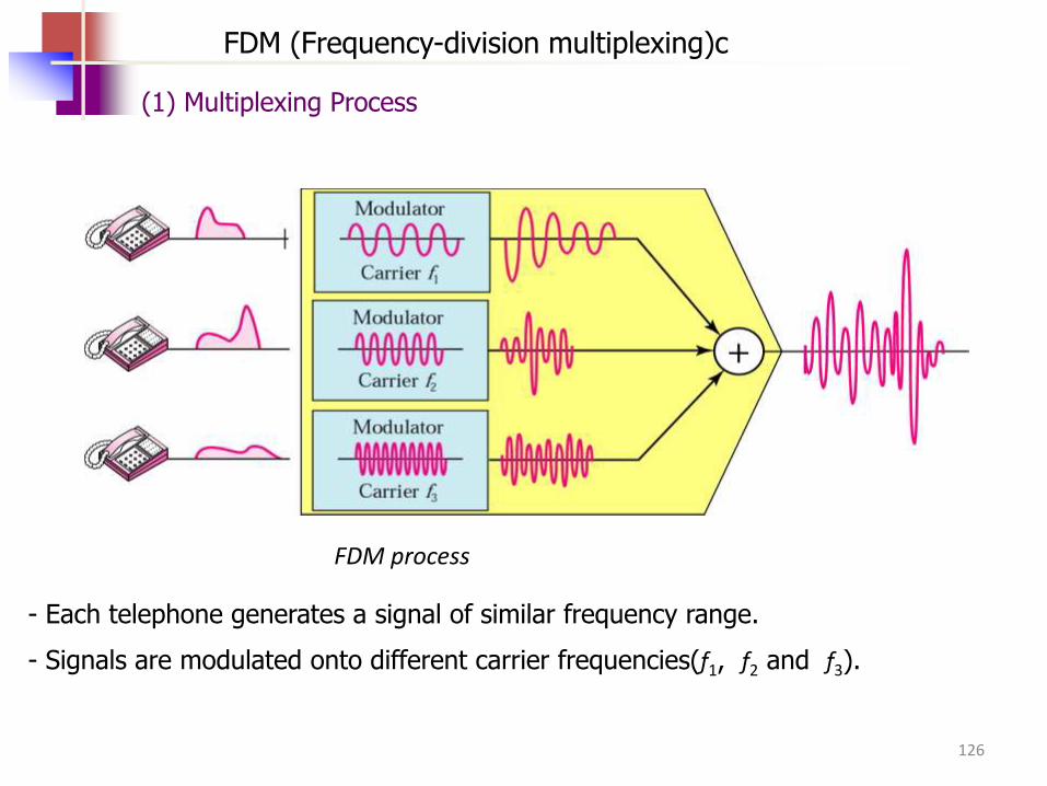
FDM process
FDM (Frequency-division multiplexing)c
- Each telephone generates a signal of similar frequency range.
- Signals are modulated onto different carrier frequencies(f1, f2 and f3).
(1) Multiplexing Process
126
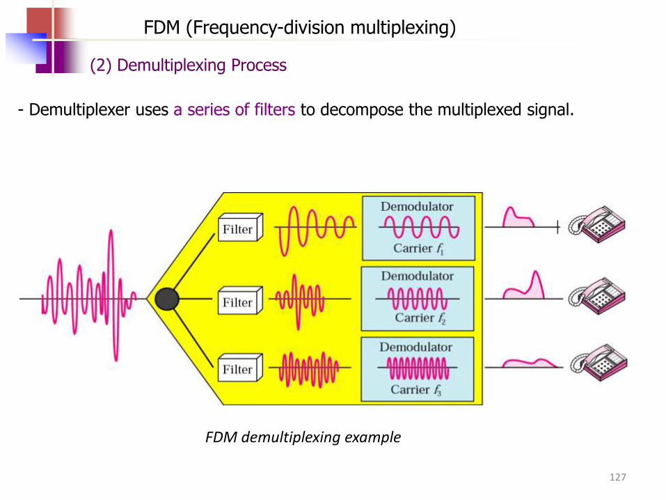
FDM demultiplexing example
FDM (Frequency-division multiplexing)
(2) Demultiplexing Process
- Demultiplexer uses a series of filters to decompose the multiplexed signal.
127
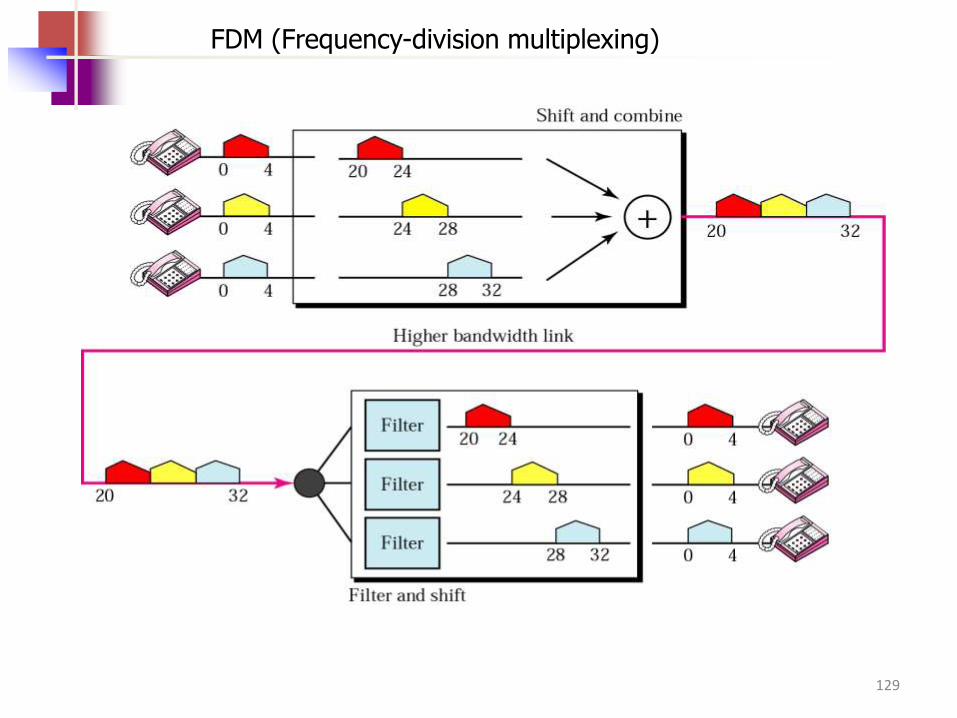
FDM (Frequency-division multiplexing)
Example 1
Assume that a voice channel occupies a bandwidth of 4 KHz. We
need to combine three voice channels into a link with a bandwidth
of 12 KHz, from 20 to 32 KHz. Show the configuration using the
frequency domain without the use of guard bands.
Solution
Shift (modulate) each of the three voice channels to a different bandwidth, as shown in Figure 6.6
128
FDM (Frequency-division multiplexing)
129
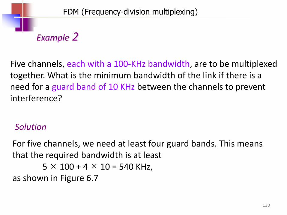
FDM (Frequency-division multiplexing)
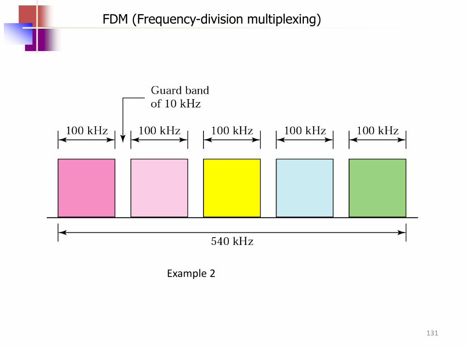
Example 2
Five channels, each with a 100-KHz bandwidth, are to be multiplexed together. What is the minimum bandwidth of the link if there is a need for a guard band of 10 KHz between the channels to prevent interference?
Solution
For five channels, we need at least four guard bands. This means that the required bandwidth is at least 5 × 100 + 4 × 10 = 540 KHz, as shown in Figure 6.7
130
Example 2
FDM (Frequency-division multiplexing)
131
FDM (Frequency-division multiplexing)
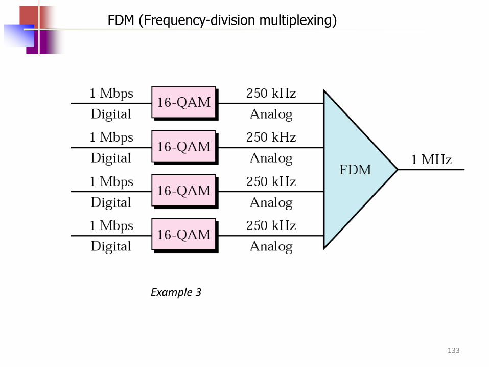
Example 3
Four data channels (digital), each transmitting at 1 Mbps, use a satellite channel of 1 MHz. Design an appropriate configuration using FDM
Solution
The satellite channel is analog. We divide it into four channels, each channel having a 250-KHz bandwidth. Each digital channel of 1 Mbps is modulated such that each 4 bits are modulated to 1 Hz. One solution is 16-QAM modulation. Figure 6.8 shows one possible configuration.
132
Example 3
FDM (Frequency-division multiplexing)
133