Embed Size (px)
Citation preview

AM Modulation -- Radio 1
http://www.technologyuk.net/telecommunications/telecom_principles/amplitude_modulation.shtml
LO audio baseband mf f f =
Amplitude Modulation – Early RadioEE 442 – Spring Semester
Lecture 6

Modulation 2
Why Use Modulation?
Most input signals, commonly created by transducers, can’t be sentdirectly over the communication channel. We refer to these signalsas baseband signals (i.e., messages or information).
Instead, a carrier wave, whose properties are better suited to thetransmission requirements, is modified (modulated) to representthe signal.
Modulation is the systematic alteration of the carrier wave so that It carriers the message or information intended to be communicated.
A. Bruce Carlson, Communication Systems: An Introduction to Signals and Noise in Electrical Communication, 2nd ed., McGraw-Hill Book Company, New York, 1975; pp. 5-7.

Modulation 3
Reasons for Using Modulation
Modulation for ease of radiation – Antennas must be greater thanone-tenth of the wavelength (/10); thus, low frequency basebandsignals would require overly large antennas.
Modulation for frequency assignment – The FCC assigns frequency bands to each radio application. Different carrier frequencies areused to meet this need.
Modulation for multiplexing – This allows for multiple signals to becarried on a single transmission medium (multiplexing is one formof modulation).
Modulation to overcome equipment limitations – Modulation is usedto place signals in a portion of the spectrum where equipment limitations are minimal or most easily met.
Modulation to reduce noise and interference – Some types ofmodulation are useful for reducing noise and interference.
A. Bruce Carlson, Communication Systems: An Introduction to Signals and Noise in Electrical Communication, 2nd ed., McGraw-Hill Book Company, New York, 1975; pp. 5-7.

Modulation 4
Modulation Options
PM
FM
AM

AM Modulation -- Radio 5
Baseband versus Carrier Communication
Baseband communication is the transmission of a message as generated is Transmitted without frequency translation.
Carrier communication requires the modulation of the message onto a carrier signal to transmit it over a different frequency band. We usemodulators to do this frequency translation.
(Note: “Pulse modulated” signals, such as PAM, PWM, PPM, PCM and DMare actually baseband digital signal coding (and not the result of frequencyconversion).
Use of Sinusoidal Carrier Signal: Using a sine waveform there are three parameters which we can use to “modulate” a message onto the carrier –they are the amplitude, frequency and phase of the sinusoidal carrier.
Signal
AM
FM

AM Modulation -- Radio 6
Amplitude modulation (AM) is a modulation technique where the amplitude of a high-frequency sine wave (called a radio frequency) is varied in direct proportion to the modulating signal m(t). The modulating signal contains the intended message or information –sometimes consisting of audio data, as in AM radio broadcasting, or two-way radio communications.
The high-frequency sinusoidal waveform (i.e., carrier) is modulated by combining it with the message signal using a multiplier or mixer (Note: mixing is a nonlinear operation because it generates new frequencies).
Amplitude Modulation Description
Agbo & Sadiku; Section 3.2, pp. 84 to 99

AM Modulation -- Radio 7
Amplitude Modulation in Pictures
100 kHz carrier modulated by a 5kHz audio tone
100 kHz carrier modulated by an audio signal
(frequencies up to 6 kHz)
5 kHz Audio tone
Tone-modulatedAM signal
Voice-modulatedAM signal
Frequency Domain Time Domain

AM Modulation -- Radio 8
As with any technology there are advantages and disadvantages to be considered.
Advantages• It is simple to implement• It can be demodulated using a circuit consisting of very few components• AM receivers are inexpensive because no specialized components are required
Disadvantages• It is not efficient with respect to power usage• It is not efficient in bandwidth; requires a bandwidth equal to twice the highest audio frequency• It is prone to high levels of noise because most noise is amplitude based and AM detectors are sensitive to it
Amplitude Modulation Advantages & Disadvantages

AM Modulation -- Radio 9
Example: Voice Signal – 300 Hz to 3400 Hz Baseband
time
amp
litu
de
m(t)
Symbol m(t) represents the source’s message signal.
Time Domain Display

AM Modulation -- Radio 10
Frequency Domain
Voice Band for Telephone Communication
Voice Channel0 Hz – 4 kHz
Voice Bandwidth300 Hz – 3.4 kHz
f0 Hz 300 Hz 3.4 kHz 4 kHz 7 kHz
PSTN or POTS
Pow
er
PSTN → Public SwitchedTelephone Network

AM Modulation -- Radio 11
3,400 Hz
Speechsignal
Speechspectra
Representative Voice Spectrum for Human Speech
For the telephone AT&T determined many years ago that speech couldbe easily recognized when the lowest frequencies and frequencies above 3.4 kilohertz were cutoff.
Waveform as received froma microphone convertingacoustic energy into electricalenergy.
Fast Fourier transform of the above speech waveformshowing energy over range of 0 Hz to 12 kHz.
Time t
Frequency f (in Hz)

AM Modulation -- Radio 12
A crystal radio receiver, also called a crystal set or cat's whisker receiver, is a very simple radio receiver, popular in the early days of radio. It needs no other power source but that received solely from the power of radio waves received by a wire antenna. It gets its name from its most important component, known as a crystal detector, originally made from a piece of crystalline mineral such as galena. This component is now called a diode.
Early AM Crystal Radio Receiver (Minimalist Radio)
Note: 1N34A is agermanium diode
that half-wave rectifies signal
Earphones
LC TunedCircuit
Demodulator

13AM Modulation -- Radio
Foxhole Radio (as used in World war I)
http://bizarrelabs.com/foxhole.htm
Ground
Coil – 120 turns of wire
Cold water pipe
Safety pinRazor blade
Earphones

AM Modulation -- Radio 14
http://www.peeblesoriginals.com/projects/images/foxhole1.jpg
Foxhole Radio (as built in a modern shop today)

AM Modulation -- Radio 15
Crystal Radio Receiver from 1922
Diagram from 1922 showing the circuit of a crystal radio. This common circuit did not use a tuning capacitor, but used the capacitance of the antenna to form the tuned circuit with the coil.
Galena (lead sulfide) was probably the most
common crystal used in “cat's whisker” detectors.
https://en.wikipedia.org/wiki/Crystal_radio
AM Modulation -- Radio 16
Amplitude Modulation (DSB with Carrier)
Amplitude Modulation: The amplitude of a carrier signal is varied linearly with a time-varying message signal.
( ) ( ) ( )
= +
+
= + = +
CNote: Keep & fixed.Carrier signal: ( ) cos( )
Only amplitude is allowed to vary in AM: ( )
( ) ( ) cos cos ( ) cos
C C
C C C
AM C C C C C
c t A t
A A A m t
t A m t t A t m t t
( )m t
cos( )C CA t
( ) cos( )C CA m t t+

AM Modulation -- Radio 17
Expressions for AM-DSB with Carrier
( ) ( ) ( )
= +
+
= + = +
CNote: Keep & fixed.Carrier signal: ( ) cos( )
Only amplitude is allowed to vary in AM: ( )
( ) ( ) cos cos ( ) cos
C C
C C C
AM C C C C C
c t A t
A A A m t
t A m t t A t m t t
( ) ( ) ( )
= + = +
=
Some books write (such as in Haykin & Moher, 2009)
( ) 1 ( ) cos cos ( ) cos
where is the "amplitude sensitivity."
And other books write (Leon W. Couch, II, 2013)
( ) 1
AM C am C C C C am C
am
AM C
t A k m t t A t A k m t t
k
t A ( ) ( ) ( ) + = + ( ) cos cos ( ) cosC C C C Cm t t A t A m t t
But other forms exist for this equation:
We will generally use this format.

AM Modulation -- Radio 18
Amplitude Modulation (DSB with Carrier) Illustrated
http://hyperphysics.phy-astr.gsu.edu/hbase/Audio/bcast.html

AM Modulation -- Radio 19
Phasor View of Amplitude Modulation
https://inspirehep.net/record/1093258/plots
Modulated oscillation is a sum of
these three vectors an is given by
the red vector. In the case of
amplitude modulation (AM), the
modulated oscillation vector is
always in phase with the carrier field
while its length oscillates with the
modulation frequency. The time
dependence of its projection onto
the real axis gives the signal
strength as drawn to the right of the
corresponding phasor diagram.
Black vector Carrier signalRed vector AM modulated signal
Example showing tone modulation

AM Modulation -- Radio 20
Phasor Expression of Amplitude Modulation
( ) Re 12 2
m m
C
j t j tj t
AM
e et e
− = + +
Ct+
mt+
mt−
Tone signal cos(mt)
Carrier cos(Ct)
C+ C m +C m −
Tone modulation
ComplexExponentialFormat
Spectrum

AM Modulation -- Radio 21
Phasor Interpretation of AM DSB with Carrier (continued)
https://www.slideshare.net/azizulhoque539/eeng-3810-chapter-4
Tone modulation
Time t

AM Modulation -- Radio 22Agbo & Sadiku; Section 3.2.1; pp. 89 to 91
Double-Sideband Amplitude Modulation Spectrum
Baseband
CarrierCarrier
Message
SidebandMessage
https://en.wikipedia.org/wiki/Amplitude_modulation
( ) ( ) ( )
( )
= + = +
= − + + + − + +1 12 2
( ) ( ) cos cos ( ) cos
The spectrum is found from the Fourier transform of ( )
( ) ( ) ( ) ( ) ( )
AM C C C C C
AM AM
AM C C C C
t m t t A t A m t t
t
FT t M M A
CarrierMessage
Frequency Shifting
Property

AM Modulation -- Radio 23
AM Modulation Index Basics – Definition
The amplitude modulation (AM) modulation index can be defined as the ratio of the peak
value of the message signal to the amplitude AC of the carrier signal.
When expressed as a percentage it is the same as the depth of modulation. In other words
it can be expressed as:
where AC is the carrier signal amplitude, and
mp is the peak modulation amplitude (maximum change in the RF amplitude
relative to its un-modulated value.
Example: An AM modulation index of 0.5 means the signal increases by a factor of 0.5,
and decreases to 0.5, centered around its unmodulated level. See drawings below.
= + ( ) ( ) cos( )AM C Ct A m t t
=Modulation Indexp
C
m
A
Agbo & SadikuPage 85-86
50% modulation illustrated

AM Modulation -- Radio 24
AM Modulation Index Basics – Examples
50% Tone Modulation
100% Tone Modulation
150% Tone Modulation
Overmodulationor
Envelope Distortion
50%
100%
150%
= + ( ) 1 cos( ) cos( )AM C m Ct A t t
=p
C
m
A
https://en.wikipedia.org/wiki/Amplitude_modulation

AM Modulation -- Radio 25
AM Overmodulation → Envelope Distortion
= = 1.50p
C
m
A
https://upload.wikimedia.org/wikipedia/commons/d/da/AM_150%25_modulation_depth.png
AM Modulation -- Radio 26
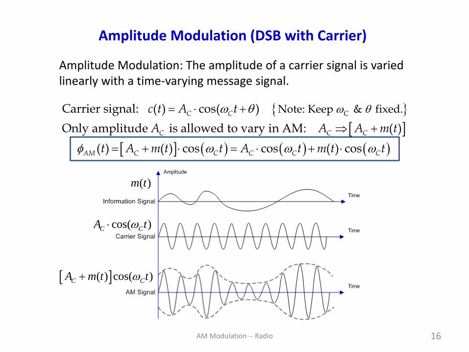
Power Efficiency of Amplitude Modulation
Agbo & Sadiku; Section 3.2.2; pp. 91 to 92
2
/2
2 2
/2
G
iven the
{Let power in one
M
sideban
A signal: ( ) cos( ) ( ) cos( )
The power in the carrier is 2
The power in the sidebands (modulated message) is
1lim ( )cos (
}
)
d
AM c c c
cc
T
S c
T
S
T
t A t m t t
AP
P m t t d
P
tT
→
−
= +
=
= =
/2
2
/2
/2
2
/2
/2
2
/2
1 1lim ( ) 1 cos(2 )
2
But ( ) cos(2 ) 0, and so
1 1 1we are left with lim ( )
2 2
That is, is one-half the total message power .
In AM the power in the mess
T
cT
T
T
c
T
T
S mT
T
S m
m t t dtT
m t t dt
P m t dt PT
P P
→−
−
→−
+
=
=
age (useful power) is the power in the
two sidebands. Next, we define .power efficiency

AM Modulation -- Radio 27
Power Efficiency in Amplitude Modulation (continued)
The power efficiency of a modulated signal is the ratio of the power inthe message part of the signal relative to the total power of themodulated signal.
212
12
2
messsage power sideband powerPower efficiency = =
total power total power
In symbols, = , and2
=
mS CC
C S C m
m
C m
PP AP
P P P P
P
A P
= =+ +
+

AM Modulation -- Radio 28
Power Efficiency in Amplitude Modulation (continued)
In general, the form of Pm is complicated and not known precisely. However,we can study AM power efficiency using a tone modulation message.
( )22 2 2
2 2 2
For tone modulation, ( ) cos( ) cos( ) ,
and2 2 2 2
p C C C
p pC
m
C p
m t m t A t
m mAP
A m
= =
= = = =+ +
0.25 0.0303 or 3.03 %
0.5 0.111 or 11.1 %
1.0 0.333 or 33.3 %
Example: (For double-sideband with carrier is AM)
2
22
=
+Modulation index =
Conclusion: AM power efficiency is very low (highly undesirable).

AM Modulation -- Radio 29
Power Efficiency in Amplitude Modulation (continued)
In general, the form of Pm is complicated and not known precisely. In practice,We find Pm by the integral,
/2 /2
2 2 2
/2 /2
/2
2
/2
/2
2 2
/2
1 1lim ( ) cos ( ) lim ( ) 1 cos (2 )
2
1lim ( ) .
2
If ( ) is a , then we have
( ) cos ( ) , then
1 1
single to
i
ne
lim cos ( ) l m
T T
m C CT T
T T
T
mT
T
p C
T
m p CT T
T
P m t t dt m t t dtT T
P m t dtT
m t
m t m t
P m t dtT
→ →− −
→−
→ →−
= = +
=
=
= =
( ) ( )
/2
2
/2
/2
2 2 2
/2
2
1 cos (2 )2
1 1 ( / 2) ( / 2) 1lim
2 2 2
1and ( )
2 4
T
p C
T
T
m p p p
TT
mS p
m t dtT
T TP m dt m m
T T
PP m
−
−→
+
− − = = =
= =

AM Modulation -- Radio 30
Can We Reduce Transmitted Power in AM?
1. Do we need to transmit the carrier, which is the majority of thetransmitted power, in AM?
No, but we will need to have a more sophisticated demodulationscheme in the receiver. We will do this with “double-sidebandsuppressed carrier” modulation.
2. Do we have to transmit both sidebands in AM?
No, because both sidebands contain identical information. Wewill do this by introducing “single-sideband modulation” (withoutcarrier).
AM Modulation -- Radio 31
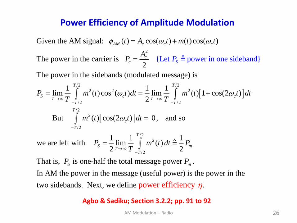
Preview: Categories of Amplitude Modulation
Baseband spectrum (message spectrum M(f))
Conventional AM (Double-SideBand With Carrier)
Double-Sideband-Suppressed Carrier (DSB-SC)
Single-Sideband /Upper Sideband SSB/USB
Single-Sideband /Lower Sideband SSB/LSB
f
f
f
f
fAlso Vestigial Sideband and Amplitude Companded SSB
Special cases of AM:
DSB-w/C
DSB-SC

AM Modulation -- Radio 32
Generation of Amplitude Modulated Signals
Agbo & Sadiku; Section 3.2.3; pp. 93 to 95
Agbo & Sadiku present two methods for AM generation:
1. Nonlinear AM modulatorAlmost any nonlinearity will work, but a very inexpensive but strongly nonlinear device is the diode. Transistors are also nonlinear and work well as modulators (but more complicated).
2. Switching AM modulatorSwitching is an easily attained function with diodes and transistors in electronic circuits.
There is also a third method:
3. Electronic multipliers (such as Gilbert cells)can be used as modulators.

AM Modulation -- Radio 33
Diode Operation Applied to AM Modulators & Demodulators
1. As nonlinear circuit components (primarily the “square law” part )
2. As “on-off” switches (they have to be driven hard to do this)
Cu
rre
nt
(mA
)
Voltage (V)
UseTaylor’sseries
approx.
( )/ 1DqV kT
D satI I e= −

AM Modulation -- Radio 34
Using Nonlinearity For Modulation (i.e., AM Generation)
R
+
_y(t)
m(t)+
_
Accos(Ct)+
_
Diode
BPFFilter(c)
+
_x(t)
The diode is the nonlinear component (it has an exponentialcharacteristic). Using a Taylor’s series we can express the diodecurrent iD as (with only first two terms of the Taylor’s series),
2
1 2
2 2
1 2 1 2
( ) ( ) ( ); ( ) is diode voltage.
The voltage across resistor R is given by
( ) ( ) ( ) ( ) ( ) ( )
D D D D
D D D D D
i t b v t b v t v t
x t i t R b Rv t b Rv t a v t a v t
= +
= = + = +
“Square Law”behavior
Di

AM Modulation -- Radio 35
Using Nonlinearity For Modulation (continued)
2
1 2
22 2
1 2
21
1
We now can evaluate voltage ( )
( ) ( ) cos ( ) ( ) cos ( )
( ) ( ) ( ) 1 cos (2 )2
2 ( )1 cos ( )
Applying the bandpass filter about , the output voltage (
C C C C
CC
C C
C
x t
x t a m t A t a m t A t
a Ax t a m t a m t t
a m ta A t
a
y
= + + +
= + + +
+ +
21
1
) is
2 ( )( ) ( ) 1 cos ( )AM C C
t
a m ty t t a A t
a
= = +
Note: For to be less than unity, we require 2
1
2 ( )1.
a m t
a
(Eq. 3.23)

AM Modulation -- Radio 36
Using Nonlinearity For Modulation (continued)
Comments:
1. Can use a general nonlinear element (not just a “square law” device)2. The filter can be as simple as a LC resonator3. This is a about the simplest of all modulators (it is unbalanced)
R
m(t)+
_
Accos(Ct)+
_
GeneralNonlinearElement
+
_y(t)C
Tuned to radianfrequency C
1C
LC =

AM Modulation -- Radio 37
Using General Nonlinearity For Modulation
fRF = 0.8fLO = 1.0
LO
RF
LO - RF LO + RF
Vout()
2LO
-R
F
3RF 3LO
2LO
+ R
F
2RF 2LO
1 2 30
2RF
–LO
2RF
+ L
O
vout RF
and LO
(linear)
v2out (
RF+
LO ), (
LO -
RF ), 2
RFand 2
LO(square law)
v3out (2
RF +
LO), (2
RF -
LO), (2
LO+
RF), (2
LO -
RF), 3
RF & 3
LO
Conclusion: Nonlinearity generates new frequencies.
2 3
out DC in in inv v Gv Av Bv= + + + +
Input signals: cos( ) cos( )in RF RF LO LOv A t B t = +
IF
Taylor’s series
tone carrier

AM Modulation -- Radio 38
Switching Amplitude Modulator – The Switch
1 2 1 1( ) cos( ) cos(3 ) cos(5 )
2 3 5C C Cp t t t t
= + − + −
Ron = 0
Roff is infinite
No Capacitance
(t)
By driving a diode with sufficient AC voltage it acts like a switch:
1
periodCf
T=
Forward bias Reverse bias
No current flowSwitch open
Current flowSwitch closed
AM Modulation -- Radio 39
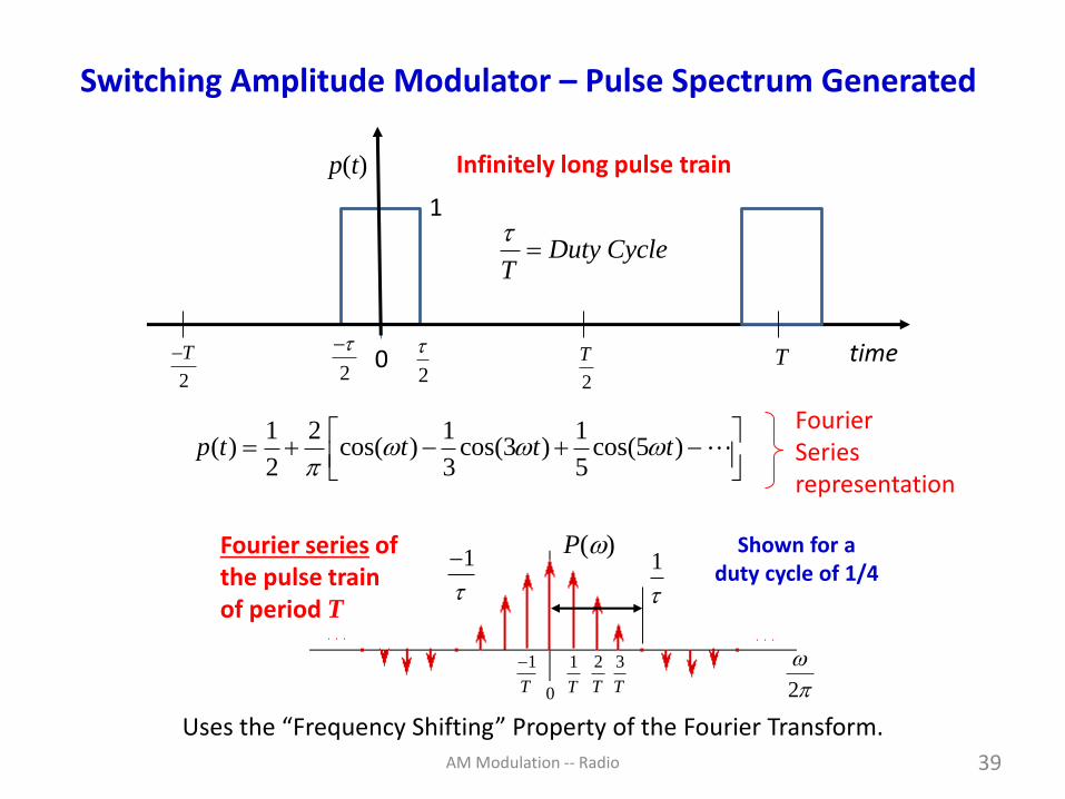
1 2 1 1( ) cos( ) cos(3 ) cos(5 )
2 3 5p t t t t
= + − + −
FourierSeriesrepresentation
Switching Amplitude Modulator – Pulse Spectrum Generated
1
p(t)
02
T
2
T−
2
T
2
− time
Infinitely long pulse train
P()
1
T
2
T
1
T
− 3
T0
Fourier series ofthe pulse trainof period T
1
1
−
Duty CycleT
=
Shown for aduty cycle of 1/4
2
Uses the “Frequency Shifting” Property of the Fourier Transform.

AM Modulation -- Radio 40
Switching Modulator – Generating m(t)cos(Ct)
Pulse trainp(t)
m(t)p(t)
Reference: Lathi & Ding,4th ed., 2009; Fig. 4.4.

AM Modulation -- Radio 41
A “hopelessly unsophisticated” mixer.
− Tom Lee (Stanford University)
The unbalanced single-diode mixer has no isolation and no conversion gain.
Single-diode mixers have been used in many applications --
(1) Detectors for radar in WW II(2) Early UHF Television tuners(3) Crystal radio detectors(4) mm-wave & sub-mm-wave
receivers
Diode Mixer For Modulation and Demodulation
IFRF +
LO
Filter
Diode
This is the same circuitused in the Foxhole radio
for demodulation.

AM Modulation -- Radio 42
AM Demodulation
Section 3.2.4 (pp. 95 to 99)
Coherent (i.e., synchronous) demodulation (or detection) is a methodto recover the message signal from the received modulated signal thatrequires a carrier at the receiver. This carrier signal must match infrequency and phase the received signal.
But . . . Amplitude Modulation has the advantage of not requiring coherent detection methods. Non-coherent methods can be used which are much simpler to implement.
1. AM Envelope Detector
2. AM Rectifier Detector

AM Modulation -- Radio 43
AM Envelope Detector Circuit
Two conditions must be met for an envelope detector to work:
(1) Narrowband [meaning fc >> bandwidth of m(t)](2) AC + m(t) 0
Incoming AMmodulated signal
Rectified AMmodulated signal
Capacitor stores energyfrom the peaks of the
rectified signal
Envelope Detection requires the an RC network with time constant = RC
Key idea: Capacitor captures the voltage peaks of rectified waveform
RC

AM Modulation -- Radio 44
Choosing the RC Time Constant in Envelope Detector
Time constant = RC too short.t
t Time constant = RC too long.
1
Design criteria is 2 2 CB fRC
How the envelope is captured
Reference: Lathi & Ding,4th ed., 2009; Fig. 4.11.
B Hz is bandwidth of message signal.

AM Modulation -- Radio 45
The user has a choice of changing the filter to meet their needs.
Practical Demodulation of an AM Signal
V V
ModulatedRF signal
inputIF output
• • •
•
•
•
IF
output
RF
AM input
Diode
DC blockingEnvelopedetection
FrequencySelectivity

AM Modulation -- Radio 46
AM Rectifier Detection
( )
= +
= + + − + −
= + +
1 13 5
( ) ( ( ))cos( ) ( )
1 2( ( ))cos( ) (cos( ) (cos(3 ) (cos(5 ) ....
2
1( ) other terms.
Note: Multiplication with ( ) allows
= dc term + baseband term
rect C C
C C C C C
C
V t A m t t p t
A m t t t t t
A m t
p t rectifier detection to act essentially as a
synchronous detection without a carrier being generated at the receiver.
DC componentis removed by
capacitor C
LPF
Reference: Lathi & Ding,4th ed., 2009; Fig. 4.10.

AM Modulation -- Radio 47
Double-Sideband Suppressed Carrier AM
Conventional AM transmits both the message and carrier signals.
Hence, the its power efficiency is low,
If (AC)2 approaches zero, then approaches 100%.
2100%m
C m
P
A P =
+
( ) ( ) cos( )
For DSB-SC (double sideband -- suppressed carrier) we have
( ) ( ) cos( ) with a FT pair ( ) ( )
1( )cos( ) ( ) ( ) ( )
2
AM C C
DSB SC C
C DSB SC C C
t A m t t
t m t t m t M
FT m t t M M
−
−
= +
=
= = − + +

AM Modulation -- Radio 48
The penalty for using DSB-SC is a complex detection scheme is needed.We can’t use simple envelope detection.
m(t) ( )DSB SC t − Phase reversals
( ) ( ) cos( )DSB SC Ct m t t − =
Double-Sideband Suppressed Carrier (continued)

AM Modulation -- Radio 49
Double-Sideband Suppressed Carrier Generation
( )m t
( )m t
( )m t−
( ) cos( )Cm t t
t →
t →
Note phasereversal
( )m t( ) cos( )Cm t t
cos( )Ct
(Modulator)
Figure 3.11 in Agbo & Sadiku
Modulation:
DSB-SC Output

AM Modulation -- Radio 50
( )DSB SC −
C m− + 0C−C m− − C m+ + C+C m+ −
TransmittedDSB-SC Signal
USBLSB
DSB-SC has USB and LSB spectra but no carrier impulses at C.
( )M
0 m+ m−
( ) ( )m t M
Double-Sideband Suppressed Carrier Spectrum
( )m t( ) cos( )Cm t t
cos( )Ct
(Modulator)

AM Modulation -- Radio 51
Double-Sideband Suppressed Carrier (continued)
Demodulation:
( )m t
( ) cos( )Cm t t
2cos( )Ct
(Modulator)
( )x t
Low-passfilter
2
2
( ) 2 ( ) cos ( ) ( ) ( ) cos(2 )
1Used the identity: cos 1 cos(2 )
2
The Fourier transform of ( ) is
1( ) ( ) ( 2 ) ( 2 )
2
C C
C C
x t m t t m t m t t
x t
X M M M
= = +
= +
= + − + +
Frequency and phasemust match.

AM Modulation -- Radio 52
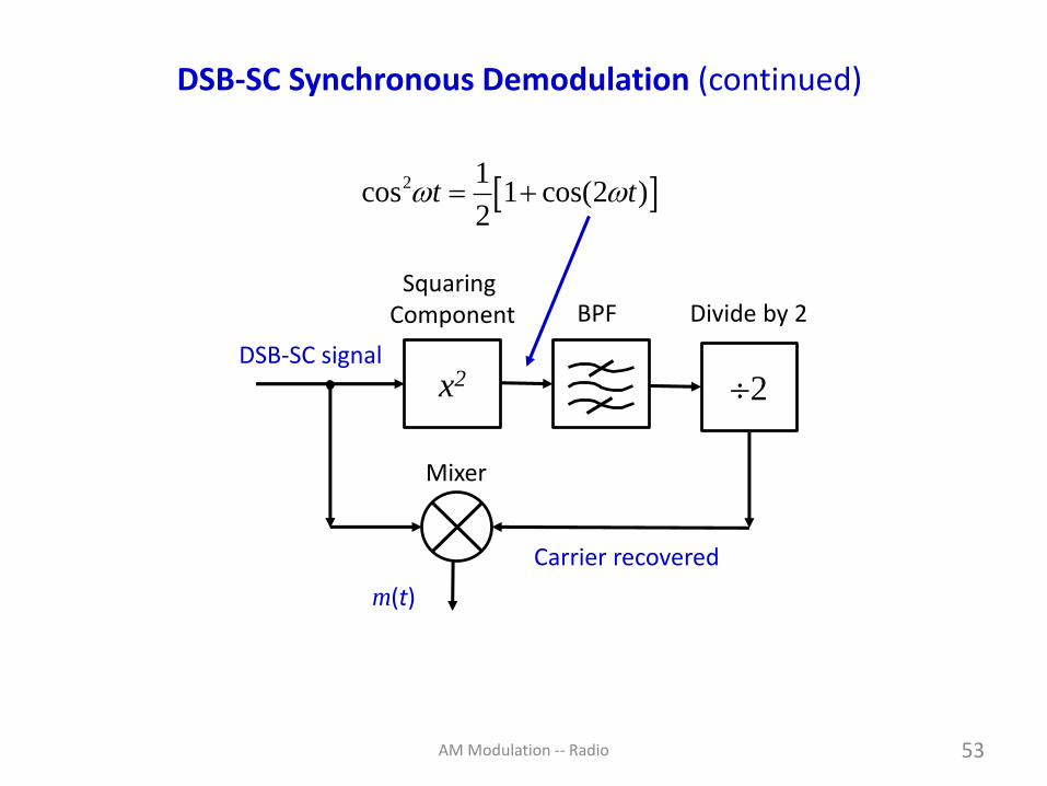
DSB-SC Synchronous Demodulation
http://www.amalgamate2000.com/radio-hobbies/radio/dsbsc____demodulation_by_the_squ.htm
Function is to providecarrier recovery
AM Modulation -- Radio 53
DSB-SC Synchronous Demodulation (continued)
x2 2DSB-SC signal
BPF
Carrier recovered
m(t)
Squaring Component
Mixer
Divide by 2
2 1cos 1 cos(2 )
2t t = +

AM Modulation -- Radio 54
Double-Sideband Suppressed Carrier (continued)
Let us examine the spectrum of the demodulated DSB-SC signal.
The message sidebands are shifted from being centered at C
back to the about the origin ( = 0) and 2C. This is illustrated
below.
Note: We now need coherent (i.e., synchronous) detection!
( )X
02 C− 2 C+
Low-pass filterSelects baseband
m+ m−
We filter out the signals centered at 2C.
Message
recovered
AM Modulation -- Radio 55
Double-Sideband Suppressed Carrier (continued)
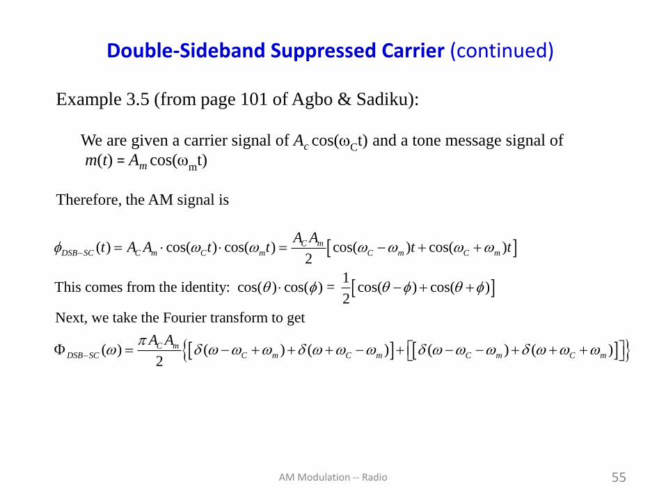
Example 3.5 (from page 101 of Agbo & Sadiku):
We are given a carrier signal of Ac cos(Ct) and a tone message signal of
m(t) = Am cos(m
t)
Therefore, the AM signal is
( ) cos( ) cos( ) cos( ) cos( )2
1This comes from the identity: cos( ) cos( ) = cos( ) cos( )
2
Next, we take the Fourier transform to get
( ) ( ) (2
C mDSB SC C m C m C m C m
C mDSB SC C m
A At A A t t t t
A A
−
−
= = − + +
− + +
= − + + ) ( ) ( )C m C m C m + − + − − + + +

AM Modulation -- Radio 56
( )DSB SC −
C m − + 0C−C m − −
( )M
0 m+m−
C m + +C+
C m + −
2
C mA A
Double-Sideband Suppressed Carrier (continued)
Tone Modulation
No carrier present

AM Modulation -- Radio 57
Analog Product Modulator
https://en.wikibooks.org/wiki/Electronics/Analog_multipliers
Log
Log
Anti-Log
BufferOutput
X
Y
outV kX Y=
DSB-SC is used primarily today for point-to-point communicationswhere a small number of receivers are involved.
One can buy commercial ICs that perform this function.
Vout

AM Modulation -- Radio 58
http://www.iitk.ac.in/eclub/ee381/AnalogMultipliers.pdf
Gilbert Cell Multiplier
VCC
-VEE
IEE
RCRC
Vin1
Vin2
C Cm
th
qI Ig
kT V= =
Vout
1 2out EE in inV I K V V=

AM Modulation -- Radio 59
Non-Linear DSB-SC Modulator
22 2 2
1 1 2 1
1
22 2 2
2 1 2 1
1
1 2 1 2
2
2 ( )( ) ( ) ( ) 1 cos(2 ) 1 cos( )
2
2 ( )( ) ( ) ( ) 1 cos(2 ) 1 cos( )
2
( ) ( ) ( ) 2 ( ) 4 ( ) cos( )
( ) 4
CC C C
CC C C
C C
DSB SC C
a A a m ts t a m t a m t t a A t
a
a A a m ts t a m t a m t t a A t
a
s t s t s t a m t a A m t t
t a A m
−
= + + + + +
= − + + + + −
= − = +
= ( ) cos( ) BPF selected thisCt t
BPF
( )DSB SC t −
Refer to slide 35 for equations.

AM Modulation -- Radio 60
Non-Linear DSB-SC Modulator (continued)
2( ) 4 ( ) cos( )DSB SC C Ct a A m t t − =
Note that this expression contains no carrier signal. Why?
Answer: The modulator is a balanced configuration and this results
in the carrier signal being cancelled (that assumes perfect balance,
of course).
Definition: A balanced modulator does not output either the carrier
component or the message component. When both are missing, we
say it is double-balanced.

AM Modulation -- Radio 61
Switching DSB-SC Modulators
Agbo & Sadiku present three switching modulators:
1. Series-bridge modulator
2. Shunt-bridge modulator, and
3. Ring modulator
We are only going to discuss the ring modulator because it is the
most widely used and contains the fundamental principle of
operation for all of them. It is important you understand how it
works.
Note: Examples of series-bridge and shunt-bridge modulators areshown in Figure 3.16 (a) and (b), page 106 of Agbo and Sadiku.

AM Modulation -- Radio 62
Ring Modulator for DSB-SC Generation
“Ring”

AM Modulation -- Radio 63
Double-Balanced Diode Ring Modulator
( ) ( )
− + −
1 1
3 5
4cos( ) cos(3 cos(5C C Ct t t
cos( )C CA t
( )cos( )Ck m t t( )m t ( )x t
( )p t
( )m t = ( ) cos( )i Cv p t t
The LO is driven hard enoughto operate the diodes
as on/off switches.
T1 T2
BPF
D1
D2
D4
D3
a b
Bipolar square wave:
1:1 1:1

AM Modulation -- Radio 64
Assume the diodes act as perfect switches (either “on” or “off”) and are controlled by the RF carrier signal (requires large amplitude).
T1T2
D1
D2
D3
D4
RF carrier signal
AC cos(ct)
m(t)
DSB-SC:
( ) cos( )Cm t t
Double-Balanced Diode Ring Modulator (continued)

AM Modulation -- Radio 65
Double-Balanced Diode Ring Modulator (continued)
Operation in the positive half-cycle of the carrier signal
T1T2
D1
D2
m(t) = 0
+
currents
These currents cancel in the primary, thus,
no output.
Diodes D3 &D4 are Off
Positive Half-Cycle:
AC cos(ct)

AM Modulation -- Radio 66
Double-Balanced Diode Ring Modulator (continued)
AC cos(ct)
Operation in the negative half-cycle of the carrier signal
T1T2
D3
D4
m(t) = 0
+
currents
These currents cancel in the
primary sono output.
Diodes D1 &D2 are Off
Negative Half-Cycle:

AM Modulation -- Radio 67
Double-Balanced Diode Ring Modulator (continued)
AC cos(ct)
Operation in the positive half-cycle of the carrier signal passes message signal m(t) to output.
Diodes D1 and D2 are “on” and the secondary of T1 is applied directly to T2.
T1T2
D1
D2
+_
+_
+
_
+_
+_
+
m(t)
+
_
+ m(t)output

AM Modulation -- Radio 68
Double-Balanced Diode Ring Modulator (continued)
AC cos(ct)
Diodes D3 and D4 are “on” and the secondary of T1 is applied directly to T2.
T1T2
D3
D4
+_
+_
+_
+_
+
_
+
m(t)
+
_
- m(t)output
Operation in the negative half-cycle of the carrier signal inverts message signal m(t) at the output.

AM Modulation -- Radio 69
Double-Balanced Diode Ring Modulator (continued)
1 2&D D on3 4&D D on
DSB-SC signal at primary of T2
m(t)
OUTPUT
LO rectangular waveform
t
https://electronicspost.com/ring-modulator-for-the-double-sideband-suppressed-carrier-generation/

AM Modulation -- Radio 70
Double-Balanced Diode Ring Modulator Waveforms
( )m t
cos(2 )C CA f t
( )cos( )Ck m t t
( ) ( )bipolarp t m t
D1 & D2 are “on”
D3 & D4 are “on”
After filtering
AM Modulation -- Radio 71
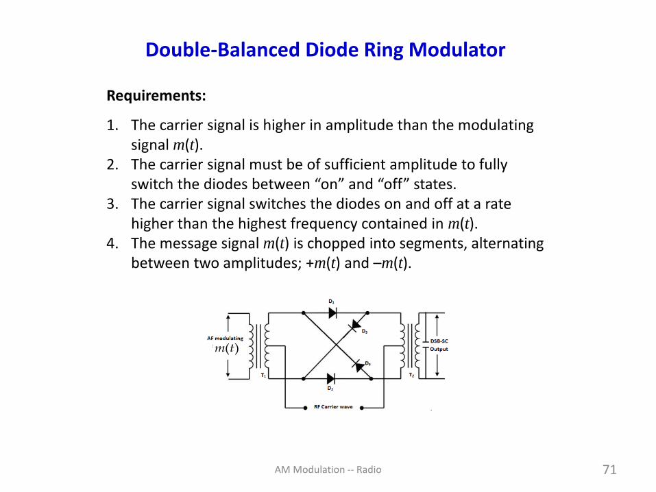
Requirements:
1. The carrier signal is higher in amplitude than the modulating signal m(t).
2. The carrier signal must be of sufficient amplitude to fully switch the diodes between “on” and “off” states.
3. The carrier signal switches the diodes on and off at a rate higher than the highest frequency contained in m(t).
4. The message signal m(t) is chopped into segments, alternating between two amplitudes; +m(t) and –m(t).
Double-Balanced Diode Ring Modulator
( )m t

AM Modulation -- Radio 72
Double-Balanced Diode Ring Modulator
( )
( )
1( ) 2 ( ) 2 ( ) 1
2
1 2 1 1( ) 2 cos cos(3 ) cos(5 )
2 3 5
4 1 1( ) cos cos(3 ) cos(5 )
3 5
Therefore, the ou
This is a bipolar square wave train.bipolar
bipolar
bipolar
C C C
C C C
p t p t p t
p t t t t
p t t t t
= − = −
= + − + −
= − + −
( )
( )
tput is found by the product,
4 ( ) ( )( ) ( ) ( ) ( ) cos cos(3 ) cos(5 )
3 5
Upon passing through the BPF,
4( ) ( ) cos
bipolar C C C
DSB SC C
m t m tx t m t p t m t t t t
t m t t
−
= = − + −
=
The mathematics behind the Diode Ring Modulator:
t
+1
-1
pbipolar(t)
. . .
. . .
. . .

AM Modulation -- Radio 73
Double-Balanced Diode Ring Modulator/Mixer
LO RF
IF
It is inexpensive and easy to build a ring mixer.
AB
C
D
GG
Trifilar-Wound Toroid
A
B
C
G
D
G
http://kambing.ui.ac.id/onnopurbo/orari-diklat/teknik/qrp/Broadband%20Transformers.htm

AM Modulation -- Radio 74
Commercial Diode Ring Mixer (Mini-Circuits)
Mixer in surface-mount package
Ring of FET devicesoperated as nonlinear
resistances
It is even easierto buy a ring mixer
component.

AM Modulation -- Radio 75
Mixers
Frequency mixing → frequency conversion → heterodyning
( )IF t( )RF t
cos( )LOt
(Mixer)
( )x t
Band-passfilter
RF
LO
IF
A mixer translates the modulation around one carrier frequency to another frequency. In a receiver, this is usually from a higher RF frequency to a lower IF frequency. In a transmitter, it’s the inverse.
We know that a LTI circuit can’t perform frequency translation. Mixers can be realized with either time-varying circuits or non-linear circuits.

AM Modulation -- Radio 76
Digression: What is Heterodyning?
Heterodyning is a signal processing technique invented in 1901 by Canadian inventor-engineer Reginald Fessenden that creates new frequencies by combining or mixing two frequencies using a nonlinear device. Edwin Armstrong invented the superheterodynereceiver in 1918.
Using an electronic circuit to combine an input radio frequency signal(RF) with another signal that is locally generated (LO) to produce new frequencies (IF): one being the sum of the two frequencies and the other being the difference of the two frequencies.
http://www.yourdictionary.com/heterodyning#SgeI5zTvo7VV96o7.99
Applications of heterodyning:1. Used in communications to generate new frequencies. 2. Move modulated signals from one frequency channel to another.3. Used in the superheterodyne radio receivers able to select from
multiple communication channels.

AM Modulation -- Radio 77
Frequency Translation By Mixing
Let ( ) ( ) cos( ) and ( ) ( ) cos( )
The local oscillator (LO) is proportional to cos( )
The mixer (or multiplier) output ( ) is given by
( ) 2 ( ) cos( ) cos( )
Choos. ing
RF C IF IF
LO
C LO
LO C IF
t m t t t m t t
t
x t
x t m t t t
A
= =
=
= −
( ) ( )
( ) ( )
, we have
( ) ( ) cos ( ) cos ( )
( ) ( ) cos (2 )
Note: Used even property of cosines [ . ., cos( ) cos( )]
Choosing , then we have
( ) ( ) co
( ) cos
.
s (
C IF C C IF C
C IF
LO C IF
C
F
IF
I
x t m t t t
x t m t t
i e
t
B
x t m t
m t
= − − + − +
= + −
− =
= +
= + −
( ) ( )
( ) ( )
) cos ( )
( ) ( ) co( ) (2 )cos sI
C C IF C
F C IF
t t
x t m t tm t t
+ + +
= + +

AM Modulation -- Radio 78
Frequency Conversion From C to IF
With a Mixer
Multiplying a modulated signal by a sinusoidal moves the frequency band to sum and difference frequencies.
Note: Super-heterodyning: c + IF ; Sub-heterodyning: c - IF
Example: We want to convert from frequency C to frequency IF .
( )x t = ( ) ( ) cos( )RF ct m t t = ( ) ( ) cos( )IF IFt m t t
( ) 2 cos ( )c IF t
= 2 f
Input frequency c Output frequency fIF
X()Filtered out
BPF response
IF −2 C IF +2 C IF2 C
→
Negative not shown
Bandpass filter (tuned
to IF)

AM Modulation -- Radio 79
Mixer Example (Example 3.7 on Page 110)
Example: Derive the relationship between LO and C so that centering the bandpass filter of the mixer is at LO - C and also ensure that IF is less than (i.e., below) C.
Answer:
We know that LO = C IF in general. We must meet two conditions:
(1) IF = LO - C and (2) IF < C
Start by assuming LO = C + IF that meets the first condition; then thesecond condition, IF < C , implies that
LO - C < C → LO < 2C

AM Modulation -- Radio 80
Superheterodyne Receiver
The superheterodyne, the circuit used in virtually all modern
radios, was invented by Edwin Armstrong in 1918 while he
worked in a US Army Signal Corps laboratory in Paris during
World War I. This is one of the receivers constructed at that
laboratory, shown in a 1920 article in an amateur radio
magazine. It is constructed in two parts. The righthand
section consists of the mixer and local oscillator. Now on
display at the Smithsonian.
https://commons.wikimedia.org/wiki/File:Prototype_Armstrong_superheterodyne_receiver_1920.jpg
Digression

AM Modulation -- Radio 81
An advertisement for the RCA Radiola AR-812 radio – it was the first
commercially produced superheterodyne radio receiver. The
superheterodyne receiver circuit was invented by US engineer Edwin
Armstrong in 1918 during World War I. The rights were purchased by
RCA, and the AR-812 was released March 4, 1924. It used 6 UV-199
triodes: a mixer, a local oscillator, two IF and two audio amplifier stages,
with an IF of 45 kHz, and was priced at $289. It was semi-portable, with
compartments for the batteries in back and a handle on top, and it
weighed 30 pounds.
https://en.wikipedia.org/wiki/Superheterodyne_receiver
First Commercial Superheterodyne Receiver

AM Modulation -- Radio 82
Advantages of the Superheterodyne Receiver
Superior selectivity in signal receptionUses fixed frequency filters allowing for excellent adjacentchannel signal rejection and also helps with image rejection.
Able to receive multiple modulation schemesAbility to incorporate a wide variety of different types ofdemodulators.
Able to receive very high frequency signalsMost of the receiver’s signal processing is done a lowerfrequencies using mixers to down convert higherfrequency incoming signals (easier to filter at lowerfrequencies, lower cost components, etc.).
The word heterodyne is derived from
the Greek roots hetero -"different", and - dyne "power".

AM Modulation -- Radio 83
Image Signals in Mixers (1)
RF IF
LO
frequency
Signal band
LORF
frequency
IF band
IF
RF
spec
trum
Desireddown-conversion
IF = LO - RF
This converts thespectrum at the RFcarrier frequency
down to the spectrumcentered at the IF
frequency.
There is no signal shown inthis part of the spectrum.

AM Modulation -- Radio 84
Image Signals in Mixers (2) – Now an Image Signal Appears
Now both the spectrum at the RF
carrier frequency andthe undesired imagespectrum are down
converted to the spectrum centered at
the IF frequency.
RF IF
LO
frequency
Signal band
Image band
LORF image
frequency
IF band
IF
RF
spec
trum
IF = LO - RF
IF = image - LO
and
But, now both signalsappear in the IF band.
The image spectrum is not wanted.

AM Modulation -- Radio 85
Image Signals in Mixers (3)
RF IF
LO
frequency
Signal band
LORF
frequency
IF band
IF
RF
spec
trum
Again, the desireddown-conversion
IF = RF - LO
This converts thespectrum at the RFcarrier frequency
down to the spectrumcentered at the IF
frequency.
Suppose the LO frequency isBelow the RF frequency.

AM Modulation -- Radio 86
Image Signals in Mixers (4) – With Image Signal
As before both the spectrum at the RF
carrier frequency andthe undesired imagespectrum are down
converted to the spectrum centered at
the IF frequency.
RF IF
LO
frequency
Signal band
LORF
frequency
IF band
IF
RF
spec
trum
IF = RF - LO
The LO frequency isbelow the RF frequency.
image
Again, both signalsappear in the IF band.
IF = LO - image
and

AM Modulation -- Radio 87
Image Rejection in a Single Mixer Heterodyne Receiver
https://en.wikipedia.org/wiki/Superheterodyne_receiver
A
A
B
B
C
C
D
D
RF channels
AM Modulation -- Radio 88
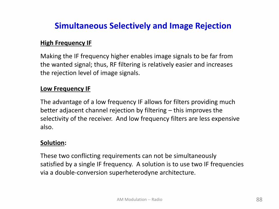
Simultaneous Selectively and Image Rejection
High Frequency IF
Making the IF frequency higher enables image signals to be far fromthe wanted signal; thus, RF filtering is relatively easier and increasesthe rejection level of image signals.
Low Frequency IF
The advantage of a low frequency IF allows for filters providing muchbetter adjacent channel rejection by filtering – this improves the selectivity of the receiver. And low frequency filters are less expensivealso.
Solution:
These two conflicting requirements can not be simultaneously satisfied by a single IF frequency. A solution is to use two IF frequenciesvia a double-conversion superheterodyne architecture.

AM Modulation -- Radio 89
A Double-Conversion Superheterodyne Receiver
https://commons.wikimedia.org/wiki/File:Double-conversion_superheterodyne_receiver_block_diagram.svg
Many high performance spectrum analyzer receivers use triple-conversion or quadruple-conversion superheterodyne architectures.
A good reference is https://www.keysight.com/upload/cmc_upload/All/5952-0292EN.pdf

AM Modulation -- Radio 90
Simplified Swept-Tuned Spectrum Analyzer Block Diagram
http://www.microwavejournal.com/articles/print/27120-part-3-overcoming-rfmicrowave-interference-challenges-in-the-field-using-rtsa
Keysight Application Note
September 15, 2016
https://www.keysight.com/upload/cmc_upload/All/5952-0292EN.pdf

AM Modulation -- Radio 91
Elenco AM/FM Dual-Radio Receiver Kit
AM
FM
Antenna
Model AM/FM-108CK Superhet Radio
Antenna
https://www.elenco.com/product/amfm-radio-kitcombo-ic-transistor/
Battery
Speaker
AM Modulation -- Radio 92
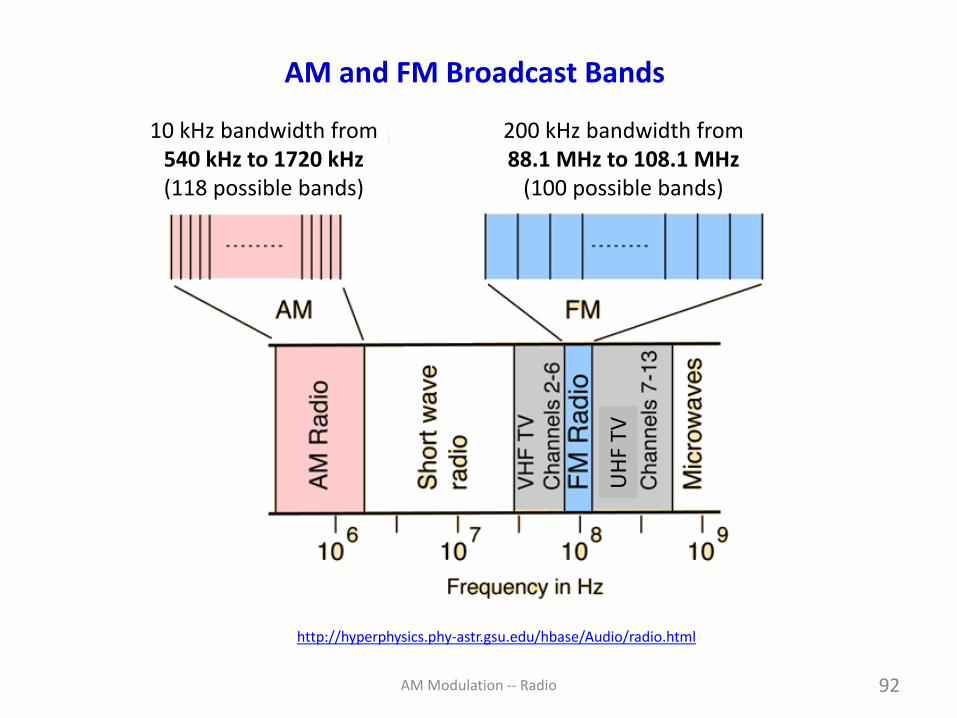
AM and FM Broadcast Bands
http://hyperphysics.phy-astr.gsu.edu/hbase/Audio/radio.html
10 kHz bandwidth from540 kHz to 1720 kHz(118 possible bands)
200 kHz bandwidth from88.1 MHz to 108.1 MHz
(100 possible bands)
UH
F TV

AM Modulation -- Radio 93
Example: AM Broadcast Stations
http://ypropubmedia.com/online-radio-advertising-services-delhi/

AM Modulation -- Radio 94
Example: Aircraft Communication (Airband)
https://aviatorsattic.com/product-category/pilot-amt-library/pilots-
library/communication/
Airband – 108 MHz to 137 MHz
108 to 117.95 MHz has 200 channels of 50 kHz each for navigational aids such as VOR beacons and precision
approach systems (ILS localizer).
118 to 136.975 MHz is divided into 2,280 channels (each 8.33 kHz of
bandwidth) for AM voice transmissions.
Instrument Landing System localizer
VHF Omni-Directional Range

AM Modulation -- Radio 95
Another Mixer Example (Practice Problem 3.8, Page 110)
For a frequency converter the carrier frequency of the output signal is 425 kHz and the carrier frequency of the AM input signal ranges from 500 kHz to 1500 kHz. Find the tuning ratio of the local oscillator
If the frequency of the local oscillator is given by (a) IF = LO - C and(b) IF = C + LO .
Answer: (a) IF = LO - C → LO = C + IF → superheterodyning
(b) IF = C + LO → LO = C - IF → sub-heterodyning
,max
,min
,LO
LO
,max ,max
,min ,min
1500 4252.081
500 425
LO C IF
LO C IF
+ += = =
+ +
,max ,max
,min ,min
1500 42514.33
500 425
LO C IF
LO C IF
− −= = =
− −

AM Modulation -- Radio 96
Quadrature Amplitude Modulation (QAM)
Fact: Both conventional AM and DSB-SC AM are wasteful of bandwidth.
One way to improve of bandwidth efficiency is with quadrature amplitudemodulation (QAM). It involves two data streams: the I-channel and theQ-channel.
Bandwidth efficiency is improved by allowing two signals to share the same bandwidth of a channel. But this can only be done if the twomodulated signals are orthogonal to each other. We now see how this can be accomplished.
A better name for QAM might be quadrature-carrier multiplexing.
https://www.rcrwireless.com/20160901/test-and-measurement/what-is-64-qam-tag6-tag99

AM Modulation -- Radio 97
Quadrature-Carrier Multiplexing (QCM)
Quadrature-carrier multiplexing allows for transmitting two message signals on the same carrier frequency.
(1) Two quadrature carriers are multiplexed together,
(2) Signal mI(t) modulates the carrier cos(Ct), and Signal mQ(t) modulates the carrier sin(Ct).
(3) The two modulated signals are added together & transmitted over the channel as
= + ( ) ( ) cos( ) ( ) sin( )QAM I C Q Ct m t t m t t

AM Modulation -- Radio 98
Quadrature Amplitude Modulation Features
1. QAM transmits two DSB-SC signals in the bandwidth of one DSB-SC signal.
2. Interference between the two modulated signals of the same frequencyis prevented by using two carriers in phase quadrature. This is becausethey are orthogonal to each other.
3. The In-phase (I-phase) channel modulates the cos(Ct) signal and the Quadrature-phase (Q-phase) channel modulates the sin (Ct) signal.
4. The carriers used in the transmitter and receiver are synchronous witheach other. In fact, they must be almost exactly in quadrature with each other, otherwise they experience cochannel interference.
5. Low-pass filters are used to extract the baseband signals mI(t) and mQ(t) in the receiver.

AM Modulation -- Radio 99
https://math.stackexchange.com/questions/474398/waves-of-differing-frequency-are-orthogonal-help-me-understand
Signals are harmonically related.
0 0sin( ) sin(2 ) 0 and cos( ) cos(2 ) 0
T T
C C C Ct t dt t t dt = =
sin(Ct)
sin(2Ct)
t
Illustrating Orthogonality With Sinusoidal Signals - I

AM Modulation -- Radio 100
Illustrating Orthogonality With Sinusoidal Signals - II
Area of product over one period is equal to zero.Therefore, the signals are orthogonal.
http://www.katjaas.nl/sinusoids2/sinusoids2.html
0sin( ) cos( ) 0
T
C Ct t dt =

AM Modulation -- Radio 101
Quadrature Amplitude Modulation (QAM)
cos( ) ( ) cos( ) ( )sin( )
where ( ) cos( ) and ( ) sin( )
C C C C
C C
A t I t t Q t t
I t A Q t A
+ = +
= =
https://www.slideshare.net/ahsanhalini/quadrature-amplitude-modulation-54999195
HSDPA (High-Speed Downlink Packet Access) is a packet-based mobile telephony protocol used in 3G UMTS radio networks.
QAM Can Be Viewed As Combination of ASK and PSK
AM Modulation -- Radio 102
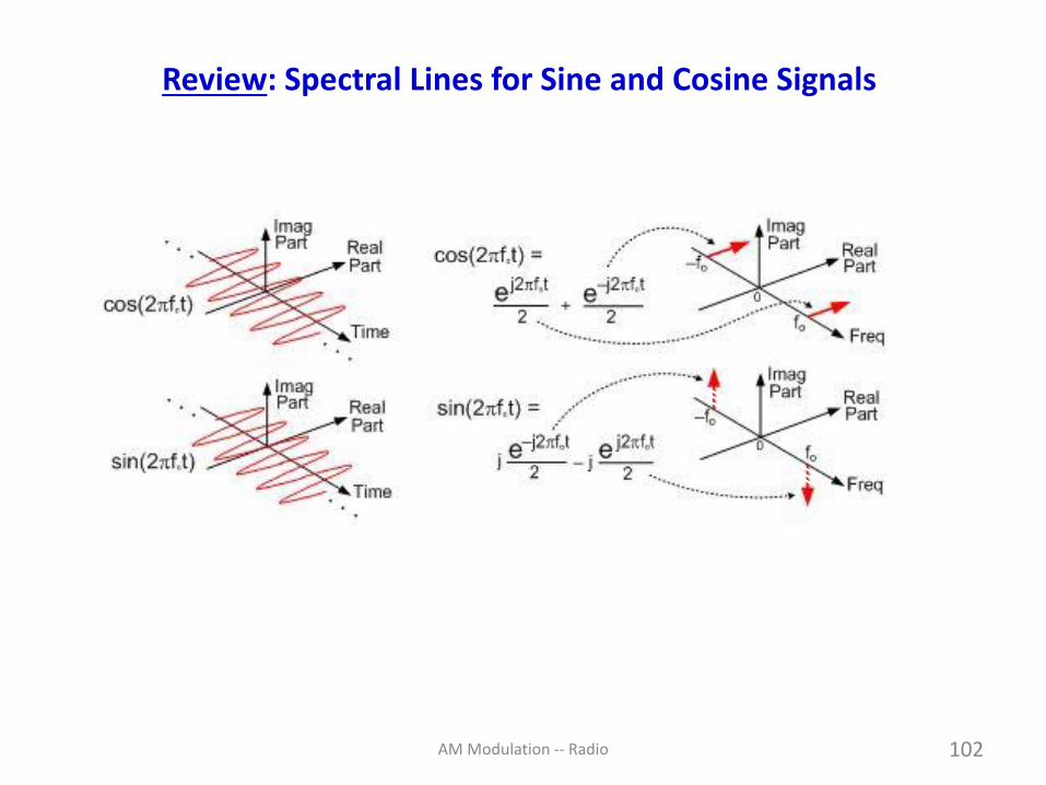
Review: Spectral Lines for Sine and Cosine Signals

AM Modulation -- Radio 103
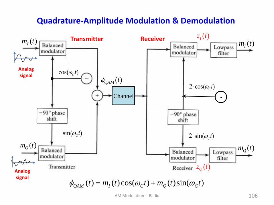
Quadrature Amplitude Modulation and Demodulation
2 cos( )Ct
2 sin( )Ct
( )Qz t
Transmitter Receiver
Channel
( )Iz t
( )QAM tcos( )Ct
sin( )Ct
− =Note: cos( 90 ) sin( )C Ct t
( )Im t
( )Qm t
( )Im t
( )Qm t
AM Modulation -- Radio 104
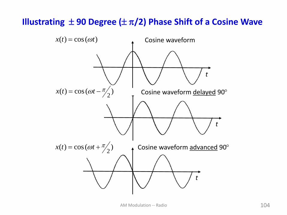
Cosine waveform
Cosine waveform delayed 90
Cosine waveform advanced 90
( ) cos ( )x t t=
2( ) cos ( )x t t = −
2( ) cos ( )x t t = +
t
t
t
Illustrating 90 Degree ( /2) Phase Shift of a Cosine Wave

AM Modulation -- Radio 105
Quadrature Amplitude Demodulation (QAM)
= +
= = +
= +
= + +
2
( ) ( )cos( ) ( )sin( )
( ) 2 cos( ) ( ) 2 cos( ) ( )cos( ) ( )sin( )
( ) 2 ( ) cos ( ) 2 ( ) cos( ) sin( )
( ) ( ) ( ) cos(2 ) ( )sin(2 )
We rec
QAM I C Q C
I C QAM C I C Q C
I I C Q C C
I I I C Q C
t m t t m t t
z t t t t m t t m t t
z t m t t m t t t
z t m t m t t m t t
= = +
= + 2
over ( ) by passing ( ) through a LPF.
and
( ) 2 sin( ) ( ) 2 sin( ) ( )cos( ) ( )sin( )
( ) 2 ( ) sin ( ) 2 ( ) sin( ) sin( )
( )
I I
Q C QAM C I C Q C
Q Q C I C C
Q
m t z t
z t t t t m t t m t t
z t m t t m t t t
z t = − +( ) ( ) cos(2 ) ( )sin(2 )
We recover ( ) by passing ( ) through a LPF.
Q Q C I C
Q Q
m t m t t m t t
m t z t Page 111Agbo & Sadiku
AM Modulation -- Radio 106
Quadrature-Amplitude Modulation & Demodulation
( ) ( ) cos( ) ( )sin( )QAM I C Q Ct m t t m t t = +
2 cos( )Ct
2 sin( )Ct
( )Qz t
Transmitter Receiver
Channel
( )Iz t
( )QAM tcos( )Ct
sin( )Ct
( )Im t ( )Im t
( )Qm t ( )Qm t
Analogsignal
Analogsignal

AM Modulation -- Radio 107
Quadrature-Amplitude Demodulation
-/2
cos(LOt)
sin(LOt)
mI(t)
LORF
mQ(t)
Quadrature Downconverter
+C-C
+LO-LO
½ ½
+C-C
+LO
-LO
+½j
-½j
+IF-IF
+IF
-IF -½j
+½j
Re
Im
Im
Re mI(t)
mQ(t)
cos(LOt)
sin(LOt)
j
IF C LO = −
Receiver

AM Modulation -- Radio 108
Re
Im
Re
Im
mI(t)
mQ(t)
Quadrature-Amplitude Demodulation (continued)
This illustrates the orthogonality of the two modulated signals.
In-phase signal occupies thereal axis-frequency plane
Quadrature signal occupies theimaginary axis-frequency plane

AM Modulation -- Radio 109
Quadrature-Amplitude Modulation & Demodulation
( ) ( ) cos( ) ( )sin( )QAM I C Q Ct m t t m t t = +
2 cos( )Ct
2 sin( )Ct
( )Qz tTransmitter Receiver
Channel
( )Iz t
( )QAM tcos( )Ct
sin( )Ct
( )Im t ( )Im t
( )Qm t ( )Qm t
Digitalsignals
Now it becomes a digital communication system

AM Modulation -- Radio 110
Quadrature-Amplitude Modulation (4-QAM)
http://www.ni.com/white-paper/3896/en/
time t
Amplitude
ConstellationDiagram

AM Modulation -- Radio 111
Effect of frequency error and phase errorin synchronous detection

AM Modulation -- Radio 112
QAM: Phase Error in Synchronous Detection
The local carrier in a DSB-SC receiver and a QAM receiver is 2cos(Ct + ),while the signal carrier at the input of each receiver is cos(Ct). Thatmeans the signal carrier and local carrier in the receivers are phase shifted relative to each other. Derive expressions for the demodulatedoutput signals for both receivers. Compare your results for DSB-SC and QAM.
Solution: (Example 3.9 on pp. 112-113)
For the DSB-SC receiver (NOT QAM):
( )=2cos( ) ( ) 2 ( ) cos( ) cos( )
( ) ( ) cos( ) ( ) cos ( )
Therefore, low-pass filering gives ( ) ( ) cos( )
C DSB SC C C
C
x t t t m t t t
x t m t m t t
y t m t
−+ = +
= + +
=
Phase error =

AM Modulation -- Radio 113
QAM: Phase Error in Synchronous Detection (continued)
1
For the QAM receiver:
( ) 2cos( ) ( ) 2cos( ) ( ) cos( ) ( ) sin( )
( ) 2 ( ) cos( ) cos( ) 2 ( ) sin( ) cos( )
( ) ( ) cos( ) ( ) cos(2 ) ( ) sin( )
I C QAM C I C Q C
I I C C Q C C
I I C Q
z t t t t m t t m t t
z t m t t t m t t t
z t m t m t t m t
= + = + +
= + + +
= + + − +
1
( ) sin(2 )
and
( ) 2sin( ) ( ) 2sin( ) ( ) cos( ) ( ) sin( )
( ) 2 ( ) cos( ) sin( ) 2 ( ) sin( ) sin( )
( ) ( ) sin( ) ( ) sin(2 ) ( ) cos( )
Q C
Q C QAM C I C Q C
Q I C C Q C C
Q I C Q
m t t
z t t t t m t t m t t
z t m t t t m t t t
z t m t m t t m t m
+
= + = + +
= + + +
= + + + − ( ) cos(2 )
The low-pass filters suppress the terms centered at 2
Therefore,
( ) ( ) cos( ) ( ) sin( )
( ) ( ) cos( ) ( ) sin( )
Q C
C
I I Q
Q Q I
t t
y t m t m t
y t m t m t
+
= −
= + Co-channel interference

AM Modulation -- Radio 114
QAM: Frequency Error in Synchronous Detection
Compare the effect of a small frequency error in the local carrier for a DSB-SC receiver and a QAM receiver. The carrier at the transmitter is cos(Ct) and the carrier at the receiver is 2cos(C+ )t.
Answer: (Example 3.10 on pp. 113-114)
( ) ( ) cos( ) ( )sin( )
( ) ( ) cos( ) ( )sin( )
I I Q
Q Q I
y t m t t m t t
y t m t t m t t
= −
= +
Note the similarity to the answer to Example 3.9.You should now be able to guess the answer to aquestion involving both phase error and frequencyerror . (Practice Problem 3.10 on page 114)

AM Modulation -- Radio 115
https://hamradioschool.com/hey-why-is-there-no-transmit-power-when-i-key-the-mic/
Single Sideband (SSB) AMModulation and Demodulation
Filter method; Phasing Method; Weaver Method

AM Modulation -- Radio 116
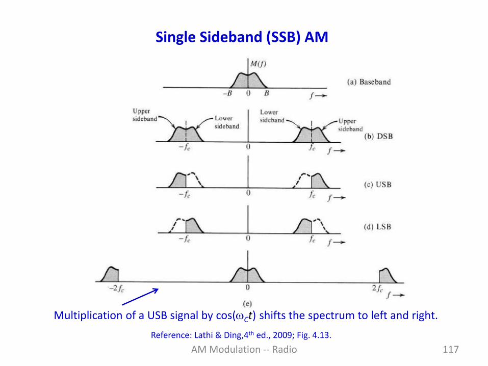
Single Sideband (SSB) AM
Why single sideband? DSB-SC is spectrally inefficient because it uses twice the bandwidth of the message. SSB addresses that issue.
The signal can be reconstructed from either the upper sideband (USB) orthe lower sideband (LSB).
SSB transmits a bandpass filtered version of the modulated signal.
Reference: Lathi & Ding,4th ed., 2009; Fig. 4.12.
AM Modulation -- Radio 117
Single Sideband (SSB) AM
Multiplication of a USB signal by cos(Ct) shifts the spectrum to left and right.
Reference: Lathi & Ding,4th ed., 2009; Fig. 4.13.

AM Modulation -- Radio 118
Phase-Shift Method to Generate SSB AM
= +( ) ( )cos( ) ( )sin( )
where minus sign applies to USB
and plus sign applies to the LSB.
( ) is ( ) phase delayed by - /2
SSB C h C
h
t m t t m t t
m t m t
Reference: Lathi & Ding,4th ed., 2009; Fig. 4.17.
HilbertTransformer

AM Modulation -- Radio 119
Reference Note: Quadrature Phase-Shifts & Hilbert Transform
sin( )tcos( )t−
2
For a + 90° (or /2) phase shift:
−
sin( ) cos( )
cos( ) sin( )
t t
t t
For a - 90° (or -/2) phase shift:
−
sin( ) cos( )
cos( ) sin( )
t t
t t
+j
-j
( ) sgn( )H j = −
=
sin( )t
+j/2
-j/2
-1/2 -1/2
cos( )t−
Hilbert transform

AM Modulation -- Radio 120
Polyphase Filter – HA5WH Network (Gingell)
BalancedAudioInput
0
90
270
180
Polyphase filters are symmetric RC structures with inputs and outputssymmetrically arranged in relative phases.
Achieves constant phase shifts over 300 Hz to about 3,000 Hz witha 60 dB rejection of the other sideband.
HA5WH Network

AM Modulation -- Radio 121
Using a Polyphase Filter in a SSB Generator
Polyphase Filter
VTO
0
90
180
270
Balanced Modulator
Balanced Modulator
90
0Driver& LPF
https://www.radioexperimenter.us/re-04-1994/phaseshifi-network-analysis-and-optimization.html
The ARRL Handbook for the Radio Amateur, (American Radio Relay League, Newington, 1993), and many previous editions.

AM Modulation -- Radio 122
Phase-Shift Method to Generate SSB AM
• The phasing method uses two balanced mixers to eliminate the carrier.
• The phasing method for SSB generation uses a phase-shift to cancel one of the sidebands.
• The carrier oscillator is applied to the upper balanced modulator along with the modulating signal.
•
• The carrier and modulating signals are both shifted by 90 degrees and applied to another modulator.
• Phase-shifting causes one sideband to cancel when the two modulator outputs are summed together.

AM Modulation -- Radio 123
Phase-Shift Method for Receiving SSB Signals
http://www.panoradio-sdr.de/ssb-demodulation/
https://www.dsprelated.com/showarticle/176.php
Reference:
I
Q
Receiver
HT

AM Modulation -- Radio 124
Synchronous Demodulation of SSB AM
https://www.dsprelated.com/showarticle/176.php
( ) 2 ( ) cos( ) ( ) cos( ) ( ) sin( ) 2cos( )
( ) ( ) ( ) cos(2 ) ( ) sin(2 )
and upon low-pass filtering we have
( ) ( )
SSB C C h C C
C h C
x t t t m t t m t t t
x t m t m t t m t t
x t m t
= =
= +
=

AM Modulation -- Radio
https://www.chegg.com/homework-help/questions-and-answers/design-ssb-modulator-using-phasing-method-weaver-s-ssb-modulator-shown-figure-matlab-simul-q21017269
Weaver’s SSB Modulator
125
Figure: Weaver’s method for generating SSB Signals

AM Modulation -- Radio 126
Hartley Image-Rejection Architecture
cos(Ct)
sin(Ct)
IF-IF
LO-LO
-IF
-IF
IF-IF
IFIF
90
RF
IF
Antenna
http://www.microwavejournal.com/articles/3226-on-the-direct-conversion-receiver-a-tutorial

AM Modulation -- Radio 127
SSB Mixer and Image Rejection Mixer Comparison
https://commons.wikimedia.org/wiki/File:SSB_and_Image_Rejection_Mixer.svg

AM Modulation -- Radio 128
Pulse Amplitude Modulation (PAM) → Digital Signal
How is PAM in digital communication similar to AM in analog communication?

AM Modulation -- Radio 129
Questions
?

AM Modulation -- Radio 130
Questions
1. What is the point of creating a rectified output when using a diode forAM modulation?
It combines the carrier signal with the message signal m(t). See slides 34, 35 & 36 for illustration of this.
2. More about how mixers work. (Three questions asked about mixers.)
Two principles are used in mixers to create new frequencies: (1) Nonlinearitythe I-V characteristics of a nonlinear device do this, and (2) time-varying switching will create new frequencies.
3. Explain the idea of images in mixers again.
See the next four slides.
From Spring 2018 EE 442 Class

AM Modulation -- Radio 131
Image Signals in Mixers (1)
RF IF
LO
frequency
Signal band
LORF
frequency
IF band
IF
RF
spec
trum
Desireddown-conversion
IF = LO - RF
This converts thespectrum at the RFcarrier frequency
down to the spectrumcentered at the IF
frequency.
There is no signal shown inthis part of the spectrum.

AM Modulation -- Radio 132
Image Signals in Mixers (2) – Now an Image Signal Appears
Now both the spectrum at the RF
carrier frequency andthe undesired imagespectrum are down
converted to the spectrum centered at
the IF frequency.
RF IF
LO
frequency
Signal band
Image band
LORF image
frequency
IF band
IF
RF
spec
trum
IF = LO - RF
IF = image - LO
and
But, now both signalsappear in the IF band.
The image spectrum is not wanted.

AM Modulation -- Radio 133
Image Signals in Mixers (3)
RF IF
LO
frequency
Signal band
LORF
frequency
IF band
IF
RF
spec
trum
Again, the desireddown-conversion
IF = RF - LO
This converts thespectrum at the RFcarrier frequency
down to the spectrumcentered at the IF
frequency.
Suppose the LO frequency isBelow the RF frequency.

AM Modulation -- Radio 134
Image Signals in Mixers (4) – With Image Signal
As before both the spectrum at the RF
carrier frequency andthe undesired imagespectrum are down
converted to the spectrum centered at
the IF frequency.
RF IF
LO
frequency
Signal band
LORF
frequency
IF band
IF
RF
spec
trum
IF = RF - LO
The LO frequency isbelow the RF frequency.
image
Again, both signalsappear in the IF band.
IF = LO - image
and

AM Modulation -- Radio 135
More Questions
4. Why does FM take so much more bandwidth than AM?
It is because we force FM (and PM) signals to have constant amplitude. We show this in detail when we cover Angle Modulation.
5. Is there a point where having too many mixers can impact your frequencynegatively?
Issues with using multiple mixers:a. Adds complexity (such as many mixing products come into play)b. Most mixers are lossy and need power gain to continue to
process signals (and mixers add noise of their own to signals)c. Cost (not only of mixers but for LO oscillators and amplifiers)

AM Modulation -- Radio 136
More Questions
6. In an antenna why does the length have to be /4?
It actually does not have to be precisely /4, but making it longer does not have an advantage in maximizing its efficiency. Making it shorterdoes decrease the signal strength received. Also, we may want theantenna to resonate at the operating frequency to increase theefficiency of the antenna.
7. Also, if an AM signal has a wavelength of hundreds of feet, how can itsantenna be so small?
The coil of wire picks up the time-variation of the electromagnetic wave’smagnetic field and induces a current in the coil which becomes the signal at the input of the AM receiver. The current increases with the numberof turns of the coil.

AM Modulation -- Radio 137
More Questions
8. When you have no carrier signal, are you sending the message signal?If so, is there even any modulation of the amplitude or justthe original signal?
In the absence of a carrier signal, then only the message signal can be sentat the frequency band of the message signal. We say the message signal “modulates” the carrier signal.
9. Does the local oscillator change its frequency depending upon the RFfrequency you want to select?
I assume you are referring to the superheterodyne receiver. Yes, the local oscillator frequency is changed to select the RF frequency you want to select. We require that frequency difference between theRF and LO frequencies is a constant.

AM Modulation -- Radio 138
More Questions
10. How is a mixer similar/different from amplitude modulation?
The mathematics of the AM says we use a multiplier to multiply the carriersignal with the message signal. A mixer performs signal multiplication as required in amplitude modulation.
11. Why do we use sub-heterodyning? What are the common applicationsof sub-heterodyning?
When analyzing a system we focus upon the RF frequencies involved andPossible local oscillator frequencies. The focus is upon frequency conversion.Considerations: Do we want to work with higher or lower frequencies? What frequency bands are to be avoided?
12. Which modulation is the most useful today? AM, FM or PM Why?
FM is the most widely used. It has better noise immunity.

AM Modulation -- Radio 139
More Questions
13. How do you build a mixer?
Example are on slides 62 and 73 illustrating the diode ring mixer.
14. How would you handle having your oscillator being 1% off?
A 1% offset in frequency is very large. You might lock it to a referencefrequency (such as a precision crystal oscillator). You might use a phase-lock loop to slave the local oscillator to the correct frequency. You mightuse a pilot signal broadcast with the modulated carrier. There are manyother possible solutions.
15. From our homework assignments what would you consider the mostimportant problems?
All of them. During the review session before the first midterm I will give amore detailed and specific answer to this question.

AM Modulation -- Radio 140
More Questions
16. What happens to an over-modulated signal? Can the signal still be used?
Over-modulation leads to distortion in the message. It can still be used in voice communication if the voice over-modulation is not too severe. The point is that voice can still be understood even with moderate distortion.
17. Why do RLC resonator circuits have a -3 dB frequency corresponding toa bandwidth of B = 1/RC?
( ) ( )
= − + + = + + +
= − =
2 22 2
1 2
2 1
1 1 1 1&
2 2 2 2
1Bandwidth
LC LCRC RC RC RC
BRC
2( )
( ) ( )Ri j L
Hi t R j L j RCL
= =
+ +

AM Modulation -- Radio 141
More Questions
R
+
_y(t)
m(t)+
_
Accos(Ct)+
_
Diode
BPFFilter(c)
+
_x(t)
The diode is the nonlinear component (it has an exponentialcharacteristic). Using a Taylor’s series we can express the diodecurrent iD as (only first two terms of Taylor’s series),
2
1 2
2 2
1 2 1 2
( ) ( ) ( ); ( ) is diode voltage.
The voltage across resistor R is given by
( ) ( ) ( ) ( ) ( ) ( )
D D D D
D D D D D
i t b v t b v t v t
x t i t R b Rv t b Rv t a v t a v t
= +
= = + = +
“Square Law”behavior
( )Di t
18. How does x(t) =iD(t)R come about? Why is it not KVL?
Remember:

AM Modulation -- Radio 142
More Questions (2018)
19. Can you explain using nonlinearity for modulation much like Problem 3 in Homework #3?
( )
( ) ( )
( ) ( ) ( )
2
2
2 2 2
( ) 4 , but 1
Substituting for ( ( ) cos( )) ,
( ) 4 ( ) cos( ) ( ) cos( )
( ) 4 ( ) cos( ) ( ) 2 ( ) cos( ) cos ( )
But we k
D D D
D C C
C C C C
C C C C C C
x t i R v v R R
v m t A t
x t m t A t m t A t
x t m t A t m t A m t t A t
= = + =
= + +
= + + + + +
= + + + + + + +
( )2
2 2now cos ( ) 1 cos(2 )2
CC C C
AA t t = +
Continued next slide →
Modulator
Given relationship

AM Modulation -- Radio 143
( ) ( ) ( )
( ) ( )( )
2 2 2
2 22
( ) 4 ( ) cos( ) ( ) 2 ( ) cos( ) cos ( )
( ) 4 ( ( )) ( ) 2 ( ) cos( ) cos(2 )2 2
The band-pass filter (BPF) passes only terms of cos( )
C C C C C C
C CC C C
C
x t m t A t m t A m t t A t
A Ax t m t m t A m t t t
t
= + + + + + + +
= + + + + + + +
( )
( )
, thus ( ) is
( ) 4 cos( ) 2 ( ( )) cos( )
( ) 4 2 cos( ) ( ) cos( )
( ) cos( ) ( ) cos( )
C C C C
C C C C
C C
y t
y t A t A m t t
y t A A t m t t
y t K t m t t
= + +
= + +
= +
Problem 3 in Homework #3 continued:
More Questions

AM Modulation -- Radio 144
More Questions
20. What is the primary form of noise production in AM systems?
The greatest noise problem in AM channels is interference, noise pickup,& fading in wireless transmission, all of which distort the amplitude of thetransmitted signal.
21. QAM (Several asked about QAM so we need to cover it again)
I will review QAM again after questions are answered.

AM Modulation -- Radio 145
( )= +2
( ) ( )y t A B g t
( )
= + = + = + +
= + +
22( ) ( ) cos( ) 1 cos(2 )
2
( ) cos(2 )2 2
By t A B g t A B t A t
B By t A t
( ) ( )= + + + +2 3
( ) ( ) ( ) ( ) .y t A Bg t C g t D g t other terms
22. Go over Problem 2 in Homework #2
Problem 2 Square Law Device (20 points)
Answer: The square-law device generates a frequency that is the double of the single tone frequency f. To show this we make use of the trigonometric identity:
Answer: The cubic term in the series generates a frequency that is triple of the frequency of g(t), that is,
frequency 3f. This comes from using the trigonometric identity of cos3(x) = ¼[3cos(x) + cos(3x)].
Thus, the cos3(2ft) term gives us both a cos(2ft) term (not so interesting) and a cos(3·2ft) term
(which is a new frequency being introduced).
More Questions
You are given a square-law component with an input to output relationship of
(a) To explore the behavior of this device we let the input signal g(t) be a sinusoidal
tone, that is, g(t) = cos(t).
(b) What frequencies does the cubic term (that is, D[g(t)]3) generate when driven by g(t) = cos(t)?

AM Modulation -- Radio 146
More Questions
23. Why does milliwatts relate to dBm rather than just use milliwatts?
We express milliwatts (mW) in decibels by
We use this because logarithms add rather than multiply in calculations.
Example:
Suppose a signal of 3 dBm power drives an amplifier of gain = 13 dB. What is theoutput power of the amplifier.
Answer: Output power (in dB) = 3 dBm + 13 dB = 16 dBm,
compared to 2 mW (= 3 dBm) multiplied by gain of 20 (= 13 dB) = 40 mW
( )10Power in dBm 10 log dBm Note: logarithm of a ratio1 mW
mWP =

AM Modulation -- Radio 147
More Questions
24. What is the one question you think we should have asked?
Answer: The one for the topic that is troubling you.

AM Modulation -- Radio 148
Additional Slides & Illustrations
https://www.stonybrook.edu/commcms/electrical/news/2017/armstrong_award.php

AM Modulation -- Radio 149
Generating m(t)cos(Ct) using Convolution
Fold, Shift & Multiply
From Convolution Theorem: (t) g(t) Cn( ) G( )
F
F
G( )
Cn( ) (t)
g(t)
Output Spectrum
LO
RF
( ) cos( )Cm t t

AM Modulation -- Radio 150
Gilbert Cell Multiplier Using FET Devices
https://www.sciencedirect.com/topics/engineering/gilbert-cell

AM Modulation -- Radio 151
https://www.exploregate.com/video.aspx?video_id=5
IIP3 = Third-order Input Intercept Point

AM Modulation -- Radio 152
Modern Mechanix (December 1952)
http://blog.modernmechanix.com/dick-tracy-wrist-radio/
Today it is reality!