Embed Size (px)
Citation preview

2 3eq 1
2 3
R R (4k )(4k )R R 1k 3kR R 4k 4k
Ω Ω= + = Ω + = Ω
+ Ω + Ω
Ohm’s law gives, T eq Teq
10VI R I 3.333mAR 3kξ
ξ = → = = =Ω
R2 & R3 are in parallel and the pair are in series with R1. Since the parallel pair each have the same resistance we know their equivalent resistance is half of either, or 4kΩ/2 = 2kΩ, which when added to R1=1kΩ gives for the equivalent resistance of the network Req = 3kΩ. Formally,

Where IT = 3.33 mA is the total current, which flows through R1. Because R2 and R3 are equal the current splits evenly between them so the current through R3 is,
T3
II 1.67mA2
= =
If we want to be more formal about it, with V = 0 on the negative side of ξ, we can calculate the potential at the junction between R1,R2 & R3 as being,
1,2,3 1V IR 10V (3.33mA)(1k ) 6.67V= ξ − = − Ω =
Since that’s then the potential across R3 , rearranging Ohm’s law,
1,2,33
eq
V 6.67VI 1.67mAR 4k
= = =Ω

If we set V=0 on the negative side of ξ1 and use the loop rule,
2 31 1 2 4
2 3
R RIR I IR 0R R
ξ − − + ξ − =+
2 31 4 1 2
2 3
R RI R RR R
+ + = ξ + ξ +
1 2
2 31 4
2 3
IR RR R
R R
ξ + ξ=
+ + +

( )1 2
2 31 4
2 3
1V 2V 3VI 0.1A10 10 10 30R RR R
R R
ξ + ξ += = = =
Ω + Ω + Ω Ω + + +
This current (0.1 A) flows through R1 splits evenly to go through the equal resistors R2 and R3 (0.05 A each) and then reconverges again to go through R4 (0.1A). The power dissipated in a resistor is where I is the current through it and R its resistance so,
2P I R=
2 21 4 2 3P P (0.1A) (10 ) 0.1W P P (0.05) 20 0.05W= = Ω = > = = Ω =

The charging time for a capacitor depends on its time constant τ = RC where C is its capacitance and R the resistance in series with it, as well as the potential across that series RC.
In (1) the potential is across a resistor, capacitor and resistor, all in series. Since the resistors are in series, their equivalent resistance is 2R and we get τ1 = 2RC.
In (2) the potential is across a parallel pair of equal resistors in series with the capacitor so τ2 = (R/2)C

In (3) the potential is across R and C in series (the potential is also across a second resistor but that will not affect the charging time of the capacitor which depends only on the resistance in series with it so, τ3 = RC.
The capacitors will charge up in the order of their time constants, smallest time constant first, so in order, τ2 = (R/2)C < τ3 = RC < τ1 = 2RC

For a charging capacitor: t
RCq C (1 e )−
= ξ −
tRCV 1 e
−= −
ξ
The voltage on the plates obeys,
t tRC RCCV (1 e ) (1 e )
C− −ξ
= − = ξ −
qq CV VC
= → =
tRC Ve 1
−= −
ξ
so,
take natural log of both sides,

tRC Vln e ln 1
− = − ξ
t Vln 1RC
− = − ξ
V tln 1RC
− = − ξ
tCVR ln 1
= − − ξ
61.10 10 FC9V(2000 ) ln 1
12V
−×= −
Ω −
10C 3.97 10 397pF−= × =

BF q(v B)= ×
km mBx y z z y ys sF q(v B v B ) e((20 )(20mT) 0 B ) e(400 T)= − = − ⋅ =
By z x x z x zF q(v B v B ) e(0 B 0 B ) 0= − = ⋅ − ⋅ =
km mBz x y y x x s sF q(v B v B ) e(v 0 (20 )(20mT)) e(400 T)= − = ⋅ − = −
m mBx p x xs s
p
eF e(400 T) m a a (400 T)m
= = ⇒ =
m mBz p z zs s
p
eF e(400 T) m a a (400 T)m
= − = ⇒ = −x y zˆ ˆ ˆa a i a j a k= + +
Then,

ms
p
e ˆ ˆa ( T)(400i 400k)m
= −
And,
( )2 2m ms s
p e
e ea ( T) 400 400 566 ( T)m m
= + =
m 2s
1910Nm m
s27 C s
1.60 10 Ca 566 ( ) 5.42 101.67 10 kg
−
−
×= = ×
×
So,

Magnitude with always perpendicular to (φ = 90o) so executes circular motion with providing the centripetal force to keep the ion on its circular orbit. Then,
B cF qvB ma= =2vqvB mr
=
mvrqB
=
BF q(v B)= ×
BF q vBsin= φ vBF
BF
For a circular orbit the velocity is the circumference 2πr divided by the time to go around once (i.e. the period, T, so):
2 rvTπ
= so, m 2 r 2 mr TqB T qB
π π= → =

253
192 m 2 (1.33 10 kg)T 1.04 10 s
eB (1.60 10 C)(0.005T)
−−
−
π π ×= = = ×
×
+ BF
z x
y
Use RHR for direction of initial deflection. Positive ion would go into +y half-plane, but the ion was negative, so goes into negative half-plane.

d = 1.00 mm = 1.00 cm
i = 10 mA B = 1.2 T
VHall = +65 nV Are the charge carriers positive or negative and what is the drift velocity?
VHall arises because carrier velocity in the ⊥ magnetic field generates a force that drives carriers to one side. Positive carriers will have a drift velocity in the direction of i. By the RHR positive carriers are deflected to the top side developing the positive hall potential there, so the carriers are positive.
(negative carriers would have velocity opposite current and would also be deflected toward top side, but then the positive VHall potential would be on the opposite ,bottom, side).

Are the charge carriers positive or negative and what is the drift velocity?
The Hall potential stops growing when the net force on the carriers due to the magnetic field is balanced by the opposing electric force in the crossed fields i.e. when,
netF q(E v B) 0= + × =
E v B 0+ × =
dE v B 0− =
dv B E=
dEvB
= But so, VEd
=
95 m
d s3V 65 10 Vv 5.4 10Bd (1.2T)(1.0 10 m)
−−
−
×= = = ×
×
d = 1.00 mm = 1.00 cm
i = 10 mA B = 1.2 T
VHall = +65 nV

Bτ = µ×
Magnitude where θ is angle between and . Here since no magnetic flux goes through the coil θ = 90o and ,
Bsinτ = µ θ
ˆNiAnµ =
,
n
, n perpendicular to loop area.
B
osin(90 ) 1=
2 3B NiAB 20(1.5A) (0.23m) (55 10 T) 1.3N m−τ = µ = = π × = ⋅

At the center of a ring of current, then here, oiB2Rµ
=
o o onet
outer inner outer inner
i i i 1 1B2R 2R 2 R R
µ µ µ= − = −
7 T5m A
net(4 10 )(4.50A) 1 1B 1.18 10 T
2 0.24m 0.12m
−−⋅π× = − = − ×
netB 11.8 T= − µ

Near the center of a long solenoid the magnetic field is uniform and given by . The potential energy of a current loop in a uniform magnetic field is,
o SB i n= µ
BU B Bcos= −µ ⋅ = −µ θ
Where is perpendicular to loop area, and θ is the angle between and . When they are parallel θ = 0, when they are anti-parallel θ = 180o.
L ˆNi Anµ = , n
n B
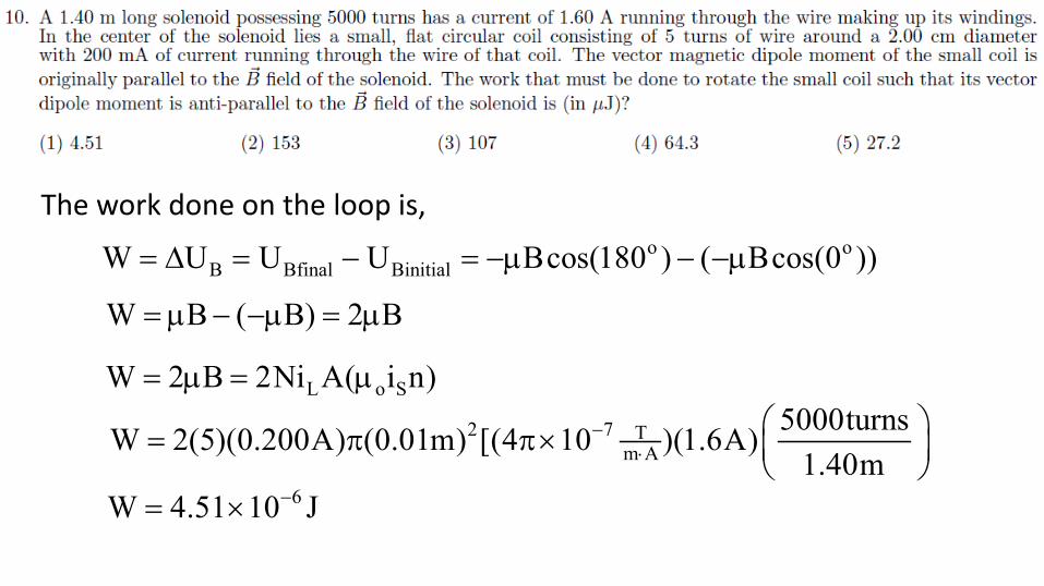
The work done on the loop is, o o
B Bfinal BinitialW U U U Bcos(180 ) ( Bcos(0 ))= ∆ = − = −µ − −µ
W B ( B) 2 B= µ − −µ = µ
L o SW 2 B 2Ni A( i n)= µ = µ2 7 T
m A5000turnsW 2(5)(0.200A) (0.01m) [(4 10 )(1.6A)
1.40m−
⋅ = π π×
6W 4.51 10 J−= ×
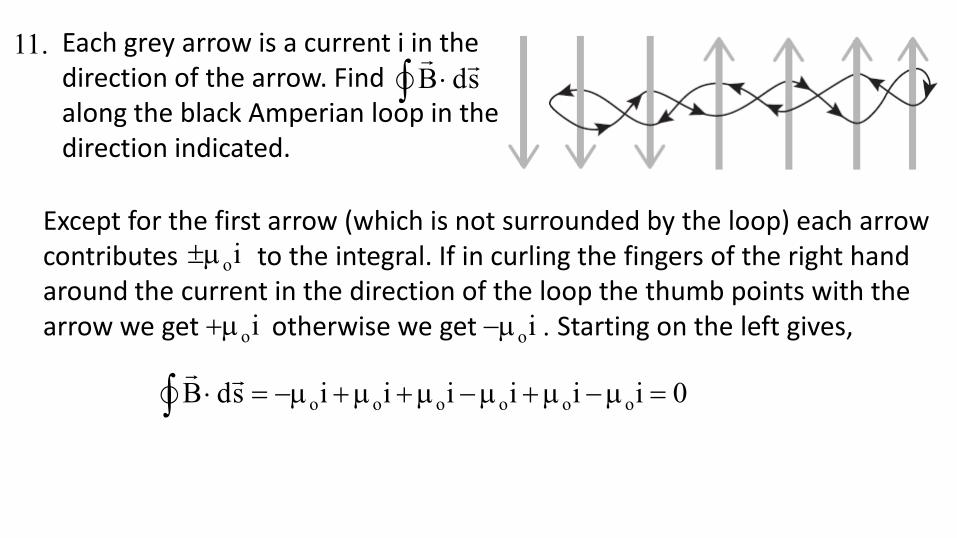
Each grey arrow is a current i in the direction of the arrow. Find along the black Amperian loop in the direction indicated.
B ds⋅∫
Except for the first arrow (which is not surrounded by the loop) each arrow contributes to the integral. If in curling the fingers of the right hand around the current in the direction of the loop the thumb points with the arrow we get otherwise we get . Starting on the left gives,
oi±µ
oi+µ oi−µ
o o o o o oB ds i i i i i i 0⋅ = −µ +µ +µ −µ +µ −µ =∫
11.

oB ds i⋅ = µ∫
For an Amperian loop concentric with the cylinder going thought point P, at radius r,
2 2 2 2i JA J( r a ) J(r a )= = π − π = π −
By symmetry B will be uniform on the loop and circulate CW, taking the integral in that direction,
2 2oB ds Bds B ds B(2 r) J(r a )⋅ = = = π = µ π −∫ ∫ ∫
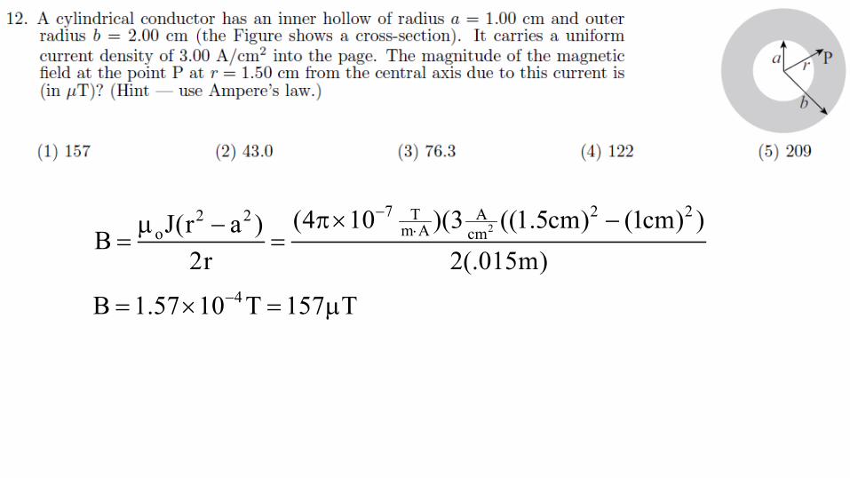
27 2 2T A2 2
m Ao cm(4 10 )(3 ((1.5cm) (1cm) )J(r a )B
2r 2(.015m)
−⋅π× −µ −
= =
4B 1.57 10 T 157 T−= × = µ

The magnetic flux through the surface is the projected area of the surface onto the plane perpendicular to times B, which is just B times the area of the bottom of the rectangular box. I.e.
B
2B
A A
B dA B dA 312mT(2.2m)(2.2m) 1.5T mΦ = ⋅ = = = ⋅∫ ∫
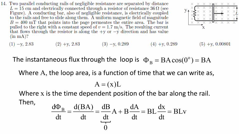
Bd d(BA) dB dA dxA B BL BLvdt dt dt dt dtΦ
= = + = =
0
oB BAcos(0 ) BAΦ = =
Where A, the loop area, is a function of time that we can write as, A (x)L=
Where x is the time dependent position of the bar along the rail. Then,
The instantaneous flux through the loop is

So, BLviR BLv iR
ξ = = → =
With into the screen, to oppose the increasing flux through the loop Lenz’s law tells us that the induced field will point out of the screen. By the RHR that implies a CCW current through the loop meaning that the current flows in the direction of –y through the resistor.
B
ms(0.4T)(0.15m)(1.7 )
i 2.83mA36
= =Ω

Since the EMF is always in a direction to oppose the change in the current (Lenz’s law), for ξL to be in the direction of i must mean that the current is decreasing. In terms of its magnitude
LdiLdt
ξ =
Ldi 60V 5.0A / sdt L 12H
ξ= = =

L
t
oi i e−τ=
L
t
o
i ei
−τ=
o L
i tlni
= − τ
, LLR
τ =
L
o
tilni
τ = −
o
L tR iln
i
= −
o
tL Rilni
= −
63.3 10 sL 1000 4.76 mH22ln44
−×= − Ω =

o 61 1 125 Hz
LC (4 H)(16 10 F)−ω = = =×

For RMS values: RMS RMSP I V cos= φ
Since oscillates in phase, means on resonance: φ = 0 and cosφ =1. So,
RMS RMSI V IV 2PP I V I
2 V2 2= = = → =
Also since on resonance, maxVV IR RI
ξ = = → =
Then, 2 2 2V V (14V)R 412P 2P 2P 2(2.4W)V
ξ= = = = = Ω

Minimizing reflected power means that on resonance. For resonance the impedance,
2 2L CZ R (X X )= + −
Is a minimum because the reactance term is zero, meaning that,
L C L CX X 0 X X− = → =
dd
1LC
ω =ω
82 2 2d
1 1 1C 5.86 10 F 58.6 nFL (2 f ) L (2 1200 Hz) (300mH)
−= = = × =ω π π⋅

( )SS P
P
N 540V V 6V 64.8VN 50
= = =
A transformer does not affect the oscillation frequency so 60 Hz, and


![Noise Reduction of Measurement Data using Linear Digital Filters · 2015. 2. 2. · the Butterworth low-pass filter has the following form [3]: () 2 2 1 c 1/n c Hj jj ω ωω = +](https://img.pdfslide.us/doc/110x75/60024dc70b54c71e58223e3f/noise-reduction-of-measurement-data-using-linear-digital-filters-2015-2-2-the.jpg)


![Time Optimal Control of Spin Systems - SysCon · ωω ω∈− +[, ] 00. BB. ε δδ∈− +[1 ,1 ] 0 0 () 0. x ut x d y vt y dt z ut vt z. ωε ωε εε −∆ − ∆−= f ()ε](https://img.pdfslide.us/doc/110x75/5ec1ae29004f764de2504864/time-optimal-control-of-spin-systems-syscon-aa-00-bb-aa.jpg)