Embed Size (px)
DESCRIPTION
Find more free manuals at www.GreenMountainGenerators.com.This manual is for the AMMPS series of the latest generation of military generator (as of 2015).
Citation preview
UNITED STATES MARINE CORPSMARINE CORPS ENGINEER SCHOOLUTILITIES INSTRUCTION COMPANY
PSC 20069CAMP LEJEUNE, NORTH CAROLINA 28542-0069
GENERATOR OPERATIONSSTUDENT OUTLINE
U-07C09JUL 2014
1. Terminal Learning Objectives.
a. At an established generator site, with electrical support plan, equipment, material, and references, operate a3kW Tactical Generator Set per TM 10155A-OI/1A, documenting operation in accordance with TM 4700-15/1H and complying with unit's mission requirements. (1141-XENG-1751)
b. At an established generator site, with electrical support plan, equipment, material, and references, operate a5kW Tactical Generator Set per TM 09292B-OI/3, documenting operation in accordance with TM 4700-15/1H and complying with unit's mission requirements. (1141-XENG-1752)
c. At an established generator site, with electrical support plan, equipment, material, and references, operate a 10kW Tactical Generator Set per TM 09247A/09248A-10/1 or TM 11783A/11784A-OI, documenting operation in accordance with TM 4700-15/1H and complying with unit's mission requirements.(1141-XENG-1753)
d. At an established generator site, with electrical support plan, equipment, material, and references, operate a15kW Tactical Generator Set per TM 11773A-OI, documenting operation in accordance with TM 4700-15/1H and complying with unit's mission requirements. (1141-XENG-1754)
e. At an established generator site, with electrical support plan, equipment, material, and references, operate a60kW Tactical Generator Set per TM 09244B/09245B-OI/1, or TM 09244C/09245C-OI, documenting operation in accordance with TM 4700-15/1H and complying with unit's mission requirements.(1141-XENG-1763)
SO 1
f. At an established generator site, with electrical support plan, equipment, material, and references, operate a100kW Tactical Generator Set per TM 07464C-10/1, documenting operation in accordance with TM 4700-15/1H and complying with unit's mission requirements. (1141-XENG-1765)
2. Enabling Learning Objectives.
a. At an established generator site, with tools, forms, and references, perform before operation checks on a Tactical Generator Set per the generator's technical manual(s). (1141-XENG-1757a)
b. At an established generator site, with tools, forms, and the reference, start a MEP-831A 3kW 60Hz Tactical Quiet Generator Set per TM 10155A-OI/1. (1141-XENG-1751a
c. At an established generator site, with tools, forms, the reference, and a running MEP-831A 3kW 60Hz Tactical Quiet Generator Set, shutdown the MEP-831A per TM 10155A-OI/1. (1141-XENG-1751b)
d. At an established generator site, with tools, forms, and the reference, start a MEP-1030 5kW 60Hz Tactical Generator Set per TM 09292B-OI/3. (1141-XENG-1752a)
e. At an established generator site, with tools, forms, the reference, and a running MEP-1030 5kW 60Hz Tactical Generator Set, shutdown the MEP-1030 per TM 09292B-OI/3. (1141-XENG-1752b)
f. At an established generator site, with tools, forms, and references, start a 10kW Tactical Generator Set per TM 09247A/09248A-10/1 or TM 11783A/11784A-OI. (1141-XENG-1753a)
g. At an established generator site, with tools, forms, references, and a running 10kW Tactical GeneratorSet, shutdown the 10kW generator per TM 09247A/09248A-10/1 or TM 11783A/11784A-OI.(1141-XENG-1753b)
h. At an established generator site, with tools, forms, and the reference, start a MEP-1050 15kW 60Hz Tactical Generator Set per TM 11773A-OI. (1141-XENG-1754a)
i. At an established generator site, with tools, forms, the reference, and a running MEP-1050 15kW 60Hz Tactical Generator Set, shutdown the MEP-1050 per TM 11773A-OI. (1141-XENG-1754b)
SO 2
j. At an established generator site, with tools, forms, and references, start a 30kW Tactical Generator Set per TM 09249B/09246B-14/1 or TM 09246C/11776A-OI. (1141-XENG-1757b)
k. At an established generator site, with tools, forms, references, and a running Tactical Generator Set, contact a load to the generator per the generator's technical manual(s). (1141-XENG-1757c)
l. At an established generator site, with tools, forms, references, and a running Tactical Generator Set, perform during operation checks and services on the generator per the generator's technical manual(s). (1141-XENG-1757d)
m. At an established generator site, with tools, forms, references, and a running 30kW Tactical Generator Set, shutdown the 30kW generator per TM 09249B/09246B-14/1 or TM 09246C/11776A-OI.(1141-XENG-1757e)
n. At an established generator site, with tools, forms, and references, start a 60kW Tactical Generator Set per TM 09244B/09245B-OI/1 or TM 09244C/09245C-OI. (1141-XENG-1763a)
o. At an established generator site, with tools, forms, references, and a running 60kW Tactical Generator Set, shutdown the 60kW generator per TM 09244B/09245B-OI/1 or TM 09244C/09245C-OI. (1141-XENG-1763b)
p. At an established generator site, with tools, forms, and the reference, start a MEP-807A 100kW 50/60Hz Tactical Quiet Generator Set per TM 07464C-10/1. (1141-XENG-1765a)
q. At an established generator site, with tools, forms, the reference, and a running MEP-807A 100kW 50/60Hz Tactical Quiet Generator Set, shutdown the MEP-807A per TM 07464C-10/1.(1141-XENG-1765b)
r. At an established generator site, with tools, forms, references, and a shutdown Tactical Generator Set, perform after operation checks on the generator per the generator's technical manual(s). (1141-XENG-1757f)
SO 3
1. MEP-831A GENERATOR SET OPERATIONS.
a. Before Operations PMCS. A before operations check is exactly what it sounds like, certain checks that are performed before a piece of equipment is operated. This is also known as a “360°,” since 360o is a complete circle. As the operator you will do a complete inspection of the equipment, visually and manually inspecting the piece of gear:
(1) Before operating any electrical equipment, ensure that the equipment is properly grounded with 10 ohms or less.
!WARNING!LACK OF A GOOD GROUND CAN RESULT IN DEATH OR SERIOUS BODILY
INJURY BY ELECTROCUTION!
(2) Inspect the housing, air ducts, exhaust grills, door fasteners, and hinges for obstructions, serviceability and proper operation.
!WARNING!THE GENERATOR SET IS DEADLINED IF THE DOORS DO NOT SECURE!
(3) Ensure the acoustical material is free of damage or not missing.
(4) Inspect the skid bases to ensure that they are not corroded or cracked.
(5) Inspect the fill neck strainer for damage. Inspect vented fuel cap and auxiliary fuel connection for obvious damage or leakage.
(6) Ensure the identification plates are secured and are in place.
(7) Inspect the control box to ensure all switches, meters, indicators, and terminals are operational.
(8) Check convenience receptacle for signs of electrical short and corrosion.
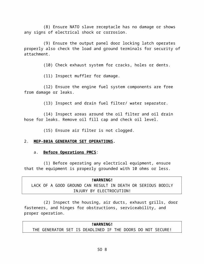
(9) Ensure NATO slave receptacle has no damage or shows any signs of electrical shock or corrosion.
SO 4
(10) Ensure the output panel door locking latch operates properly, also check the load and ground terminals to ensure they are securely attached.
(11) Check exhaust system for cracks, holes or dents.
(12) Inspect muffler for damage.
(13) Ensure the engine fuel system components are free from damage or leaks.
(14) Inspect and drain fuel filter/water separator.
(15) Inspect areas around the oil filter and oil drain hose for leaks. Remove oil fill cap and check oil level.
(16) Ensure air filter is not clogged.
b. Starting Procedures:
(1) Push in DC CIRCUIT BREAKER.
(2) Place START/RUN/STOP switch in the start position. (switch is spring loaded and must be held in place) Release switch to RUN position once the engine starts.
(3) Adjust voltage as required by using the VOLTAGE ADJUST rheostat.
(4) Place the AC CIRCUIT INTERRUPTER switch in the CLOSED position.
c. During Operations PMCS:
(1) Monitor the voltage and load output levels.
(2) Monitor fuel level.
(3) Look, listen, and smell for anything unusual coming from the generator set.
SO 5
d. Shutdown Procedures:
(1) Place the AC CIRCUIT INTERRUPTER switch in the OPEN position. Allow the generator 3-5 minutes to cool down the engine.
(2) Place the START/RUN/STOP switch in the STOP position.
(3) Pull out the DC CIRCUIT BREAKER.
e. After Operations PMCS:
(1) Inspect the housing, air ducts, exhaust grills, door fasteners and hinges for obstructions, serviceability, and proper operation.
(2) Ensure the acoustical material is free of damage or not missing.
(3) Inspect the skid bases to ensure that they are not corroded or cracked.
(4) Inspect the fill neck strainer for damage. Inspect vented fuel cap and auxiliary fuel connection for obvious damage or leakage.
(5) Ensure the identification plates are secured and are in place.
(6) Inspect the control box to ensure all switches, meters, indicators and terminals are operational.
(7) Check convenience receptacle for signs of electrical short and corrosion.
(8) Ensure NATO slave receptacle has no damage or shows any signs of electrical shock or corrosion.
(9) Ensure the output panel door locking latch operates properly also check the load and ground terminals for security of attachment.
(10) Check exhaust system for cracks, holes or dents.
(11) Inspect muffler for damage.
SO 6
(12) Ensure the engine fuel system components are free from damage or leaks.
(13) Inspect and drain fuel filter/ water separator.
(14) Inspect areas around the oil filter and oil drain hose for leaks. Remove oil fill cap and check oil level.
(15) Ensure air filter is not clogged.
2. MEP-803A GENERATOR SET OPERATIONS.
a. Before Operations PMCS:
(1) Before operating any electrical equipment, ensure that the equipment is properly grounded with 10 ohms or less.
!WARNING!LACK OF A GOOD GROUND CAN RESULT IN DEATH OR SERIOUS BODILY
INJURY BY ELECTROCUTION!
(2) Inspect the housing, air ducts, exhaust grills, door fasteners, and hinges for obstructions, serviceability, and proper operation.
!WARNING!THE GENERATOR SET IS DEADLINED IF THE DOORS DO NOT SECURE!
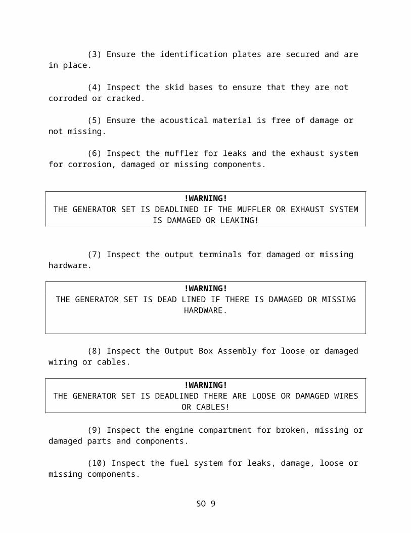
(3) Ensure the identification plates are secured and are in place.
(4) Inspect the skid bases to ensure that they are not corroded or cracked.
(5) Ensure the acoustical material is free of damage or not missing.
(6) Inspect the muffler for leaks and the exhaust system for corrosion, damaged or missing components.
!WARNING!THE GENERATOR SET IS DEADLINED IF THE MUFFLER OR EXHAUST SYSTEM
IS DAMAGED OR LEAKING!
SO 7
(7) Inspect the output terminals for damaged or missing hardware.
!WARNING!THE GENERATOR SET IS DEAD LINED IF THERE IS DAMAGED OR MISSING
HARDWARE.
(8) Inspect the Output Box Assembly for loose or damaged wiring or cables.
!WARNING!THE GENERATOR SET IS DEADLINED THERE ARE LOOSE OR DAMAGED WIRES
OR CABLES!
(9) Inspect the engine compartment for broken, missing or damaged parts and components.
(10) Inspect the fuel system for leaks, damage, loose or missing components.
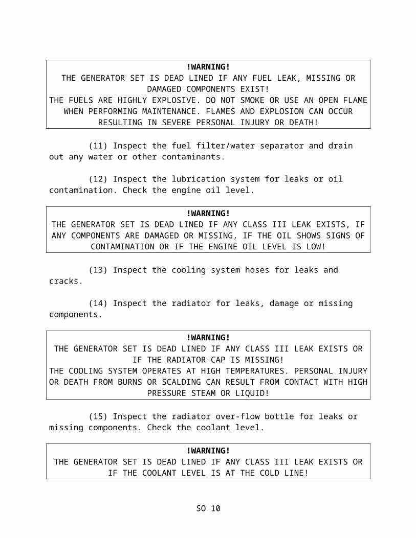
!WARNING!THE GENERATOR SET IS DEAD LINED IF ANY FUEL LEAK, MISSING OR
DAMAGED COMPONENTS EXIST!THE FUELS ARE HIGHLY EXPLOSIVE. DO NOT SMOKE OR USE AN OPEN FLAME
WHEN PERFORMING MAINTENANCE. FLAMES AND EXPLOSION CAN OCCUR RESULTING IN SEVERE PERSONAL INJURY OR DEATH!
(11) Inspect the fuel filter/water separator and drain out any water or other contaminants.
(12) Inspect the lubrication system for leaks or oil contamination. Check the engine oil level.
!WARNING!THE GENERATOR SET IS DEAD LINED IF ANY CLASS III LEAK EXISTS, IF ANY COMPONENTS ARE DAMAGED OR MISSING, IF THE OIL SHOWS SIGNS OF
CONTAMINATION OR IF THE ENGINE OIL LEVEL IS LOW!
(13) Inspect the cooling system hoses for leaks and cracks.
(14) Inspect the radiator for leaks, damage or missing components.
SO 8
!WARNING!THE GENERATOR SET IS DEAD LINED IF ANY CLASS III LEAK EXISTS OR
IF THE RADIATOR CAP IS MISSING!THE COOLING SYSTEM OPERATES AT HIGH TEMPERATURES. PERSONAL INJURY OR DEATH FROM BURNS OR SCALDING CAN RESULT FROM CONTACT WITH HIGH
PRESSURE STEAM OR LIQUID!
(15) Inspect the radiator over-flow bottle for leaks or missing components. Check the coolant level.
!WARNING!THE GENERATOR SET IS DEAD LINED IF ANY CLASS III LEAK EXISTS OR
IF THE COOLANT LEVEL IS AT THE COLD LINE!
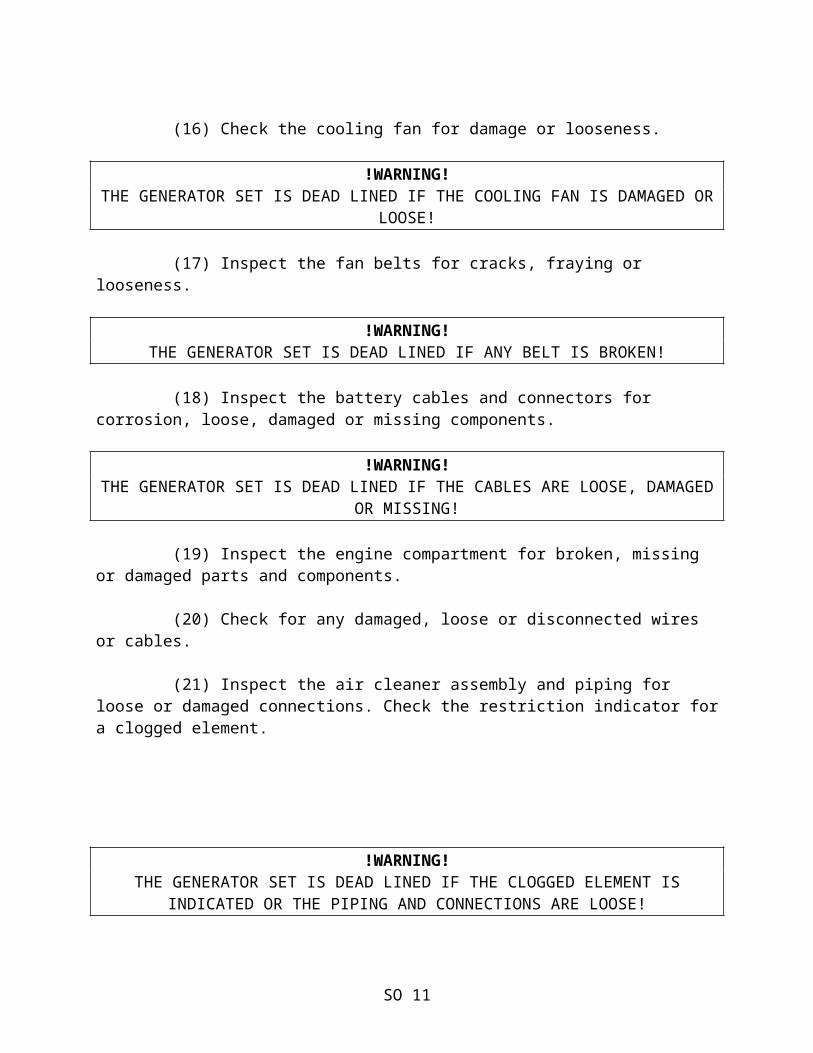
(16) Check the cooling fan for damage or looseness.
!WARNING!THE GENERATOR SET IS DEAD LINED IF THE COOLING FAN IS DAMAGED OR
LOOSE!
(17) Inspect the fan belts for cracks, fraying or looseness.
!WARNING!THE GENERATOR SET IS DEAD LINED IF ANY BELT IS BROKEN!
(18) Inspect the battery cables and connectors for corrosion, loose, damaged or missing components.
!WARNING!THE GENERATOR SET IS DEAD LINED IF THE CABLES ARE LOOSE, DAMAGED
OR MISSING!
(19) Inspect the engine compartment for broken, missing or damaged parts and components.
(20) Check for any damaged, loose or disconnected wires or cables.
(21) Inspect the air cleaner assembly and piping for loose or damaged connections. Check the restriction indicator for a clogged element.
SO 9
!WARNING!THE GENERATOR SET IS DEAD LINED IF THE CLOGGED ELEMENT IS
INDICATED OR THE PIPING AND CONNECTIONS ARE LOOSE!
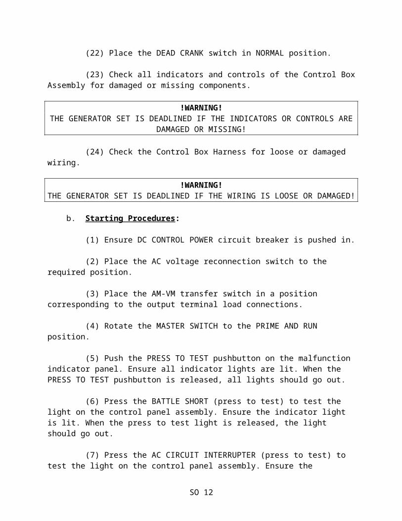
(22) Place the DEAD CRANK switch in NORMAL position.
(23) Check all indicators and controls of the Control Box Assembly for damaged or missing components.
!WARNING!THE GENERATOR SET IS DEADLINED IF THE INDICATORS OR CONTROLS ARE
DAMAGED OR MISSING!
(24) Check the Control Box Harness for loose or damaged wiring.
!WARNING!THE GENERATOR SET IS DEADLINED IF THE WIRING IS LOOSE OR DAMAGED!
b. Starting Procedures:
(1) Ensure DC CONTROL POWER circuit breaker is pushed in.
(2) Place the AC voltage reconnection switch to the required position.
(3) Place the AM-VM transfer switch in a position corresponding to the output terminal load connections.
(4) Rotate the MASTER SWITCH to the PRIME AND RUN position.
(5) Push the PRESS TO TEST pushbutton on the malfunction indicator panel. Ensure all indicator lights are lit. When the PRESS TO TEST pushbutton is released, all lights should go out.
(6) Press the BATTLE SHORT (press to test) to test the light on the control panel assembly. Ensure the indicator light is lit. When the press to test light is released, the light should go out.
(7) Press the AC CIRCUIT INTERRUPTER (press to test) to test the light on the control panel assembly. Ensure the indicator light is lit. When the press to test light is released, the light should go out.
SO 10
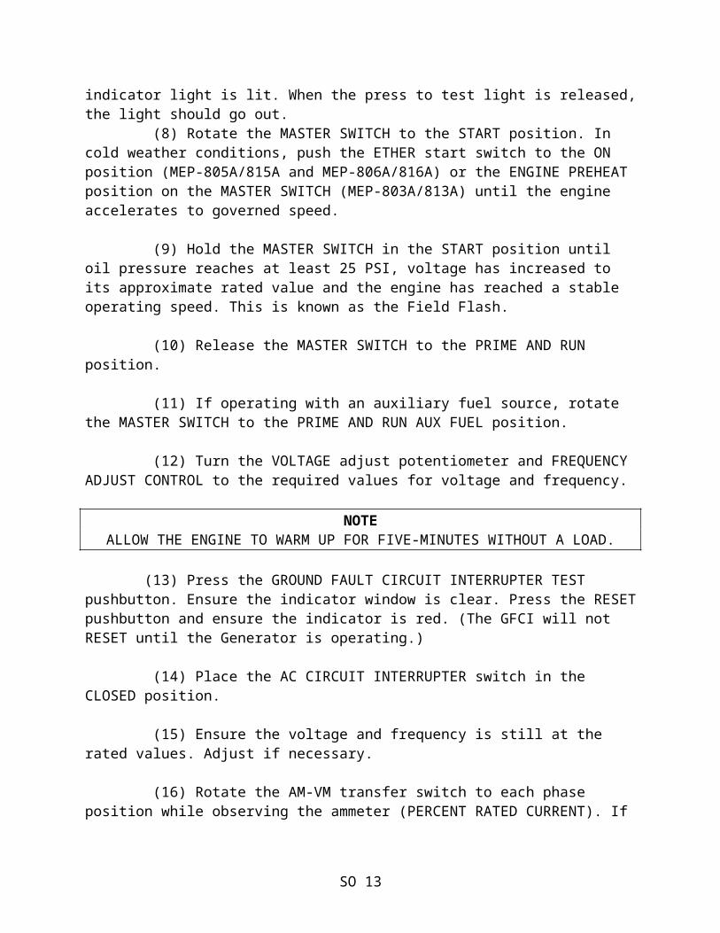
(8) Rotate the MASTER SWITCH to the START position. In cold weather conditions, push the ETHER start switch to the ON position (MEP-805A/815A and MEP-806A/816A) or the ENGINE PREHEAT position on the MASTER SWITCH (MEP-803A/813A) until the engine accelerates to governed speed.
(9) Hold the MASTER SWITCH in the START position until oil pressure reaches at least 25 PSI, voltage has increased to its approximate rated value and the engine has reached a stable operating speed. This is known as the Field Flash.
(10) Release the MASTER SWITCH to the PRIME AND RUN position.
(11) If operating with an auxiliary fuel source, rotate the MASTER SWITCH to the PRIME AND RUN AUX FUEL position.
(12) Turn the VOLTAGE adjust potentiometer and FREQUENCY ADJUST CONTROL to the required values for voltage and frequency.
NOTEALLOW THE ENGINE TO WARM UP FOR FIVE-MINUTES WITHOUT A LOAD.
(13) Press the GROUND FAULT CIRCUIT INTERRUPTER TEST pushbutton. Ensure the indicator window is clear. Press the RESET pushbutton and ensure the indicator is red. (The GFCI will not RESET until the Generator is operating.)
(14) Place the AC CIRCUIT INTERRUPTER switch in the CLOSED position.
(15) Ensure the voltage and frequency is still at the rated values. Adjust if necessary.
(16) Rotate the AM-VM transfer switch to each phase position while observing the ammeter (PERCENT RATED CURRENT). If more than the rated phase is indicated on any phase, reduce the load.
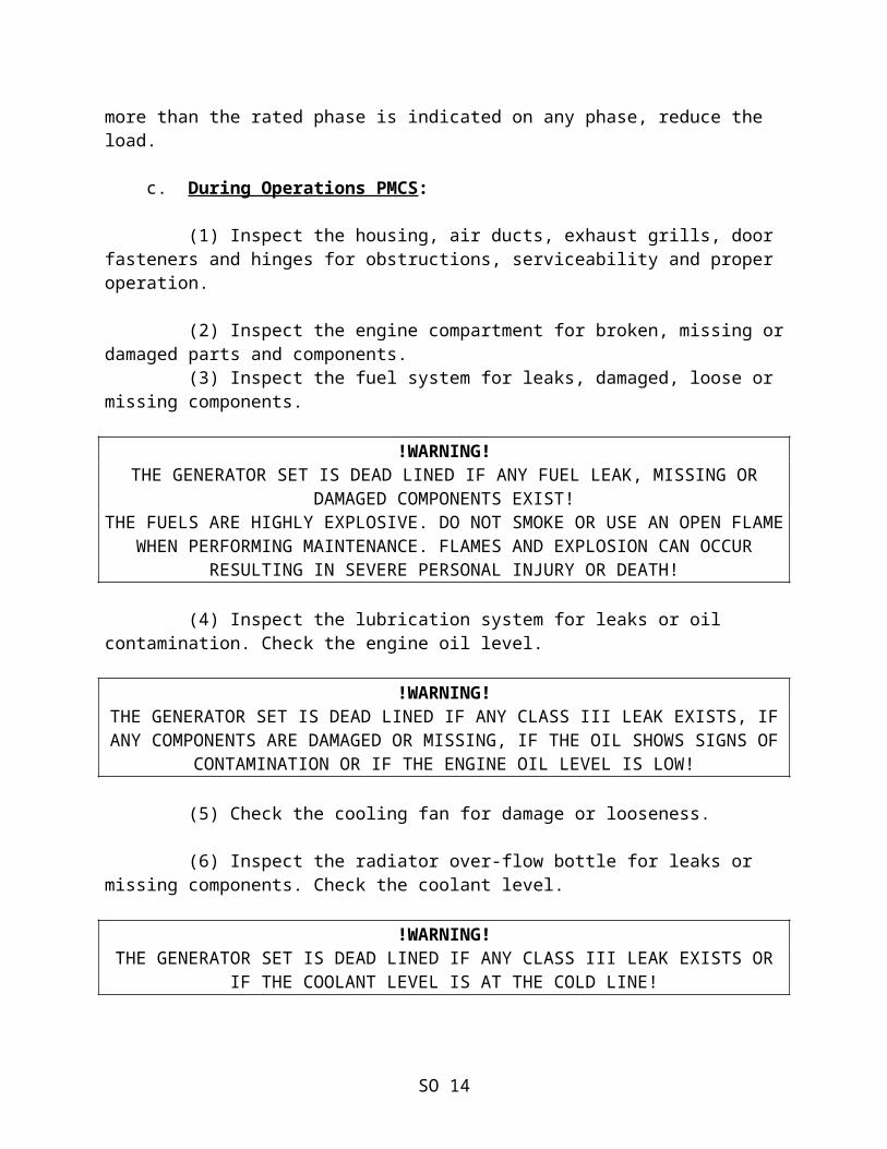
c. During Operations PMCS:
(1) Inspect the housing, air ducts, exhaust grills, door fasteners and hinges for obstructions, serviceability and proper operation.
(2) Inspect the engine compartment for broken, missing or damaged parts and components.
SO 11
(3) Inspect the fuel system for leaks, damaged, loose or missing components.
!WARNING!THE GENERATOR SET IS DEAD LINED IF ANY FUEL LEAK, MISSING OR
DAMAGED COMPONENTS EXIST!THE FUELS ARE HIGHLY EXPLOSIVE. DO NOT SMOKE OR USE AN OPEN FLAME
WHEN PERFORMING MAINTENANCE. FLAMES AND EXPLOSION CAN OCCUR RESULTING IN SEVERE PERSONAL INJURY OR DEATH!
(4) Inspect the lubrication system for leaks or oil contamination. Check the engine oil level.
!WARNING!THE GENERATOR SET IS DEAD LINED IF ANY CLASS III LEAK EXISTS, IF ANY COMPONENTS ARE DAMAGED OR MISSING, IF THE OIL SHOWS SIGNS OF
CONTAMINATION OR IF THE ENGINE OIL LEVEL IS LOW!
(5) Check the cooling fan for damage or looseness.
(6) Inspect the radiator over-flow bottle for leaks or missing components. Check the coolant level.
!WARNING!THE GENERATOR SET IS DEAD LINED IF ANY CLASS III LEAK EXISTS OR
IF THE COOLANT LEVEL IS AT THE COLD LINE!
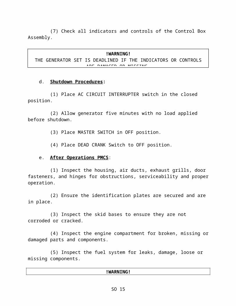
(7) Check all indicators and controls of the Control Box Assembly.
d. Shutdown Procedures:
(1) Place AC CIRCUIT INTERRUPTER switch in the closed position.
(2) Allow generator five minutes with no load applied before shutdown.
(3) Place MASTER SWITCH in OFF position.
(4) Place DEAD CRANK Switch to OFF position.
SO 12
!WARNING!THE GENERATOR SET IS DEADLINED IF THE INDICATORS OR CONTROLS
ARE DAMAGED OR MISSING.
e. After Operations PMCS:
(1) Inspect the housing, air ducts, exhaust grills, door fasteners, and hinges for obstructions, serviceability and proper operation.
(2) Ensure the identification plates are secured and are in place.
(3) Inspect the skid bases to ensure they are not corroded or cracked.
(4) Inspect the engine compartment for broken, missing or damaged parts and components.
(5) Inspect the fuel system for leaks, damage, loose or missing components.
!WARNING!THE GENERATOR SET IS DEAD LINED IF ANY FUEL LEAK, MISSING OR
DAMAGED COMPONENTS EXIST!THE FUELS ARE HIGHLY EXPLOSIVE. DO NOT SMOKE OR USE AN OPEN FLAME
WHEN PERFORMING MAINTENANCE. FLAMES AND EXPLOSION CAN OCCUR RESULTING IN SEVERE PERSONAL INJURY OR DEATH!
(6) Inspect the fuel filter/water separator and drain out any water or other contaminants.
(7) Inspect the lubrication system for leaks or oil contamination. Check the engine oil level.
!WARNING!THE GENERATOR SET IS DEAD LINED IF ANY CLASS III LEAK EXISTS, IF ANY COMPONENTS ARE DAMAGED OR MISSING, IF THE OIL SHOWS SIGNS OF
CONTAMINATION OR IF THE ENGINE OIL LEVEL IS LOW!
(8) Inspect the cooling system hoses for leaks and cracks.
(9) Inspect the radiator for leaks, damage or missing components.
!WARNING!THE GENERATOR SET IS DEAD LINED IF ANY CLASS III LEAK EXISTS OR
IF THE RADIATOR CAP IS MISSING!
SO 13
THE COOLING SYSTEM OPERATES AT HIGH TEMPERATURES. PERSONAL INJURY OR DEATH FROM BURNS OR SCALDING CAN RESULT FROM CONTACT WITH HIGH
PRESSURE STEAM OR LIQUID!
(10) Inspect the radiator over-flow bottle for leaks or missing components. Check the coolant level.
!WARNING!THE GENERATOR SET IS DEAD LINED IF ANY CLASS III LEAK EXISTS OR
IF THE COOLANT LEVEL IS AT THE COLD LINE!
(11) Check the cooling fan for damage or looseness.
!WARNING!THE GENERATOR SET IS DEAD LINED IF THE COOLING FAN IS DAMAGED OR
LOOSE!
(12) Inspect the fan belts for cracks, fraying or looseness.
!WARNING!THE GENERATOR SET IS DEAD LINED IF ANY BELT IS BROKEN!
(13) Check all indicators and controls of the Control Box Assembly.
3. TQG BRAVO OPERATIONS.
a. Before Operations Checks. The procedures for starting the TQG Bravo are the same as they were for all TQG Sets.
b. Starting Procedures:
(1) Turn the dead crank switch to the normal position. Also the Battery Current Transformer located on the right side of the engine, just below the alternator, needs to be pushed in.
SO 14
!WARNING!THE GENERATOR SET IS DEADLINES IF THE INDICATORS OR CONTROLS ARE
DAMAGED OR MISSING
(2) Place the Master Control Switch in the ON position. Turn Panel Lights to the ON position. Computer software will begin to load, wait until the Computer Interface Module (CIM) screen appears this is the MAIN SCREEN. The Network Failure light will illuminate until software is completely loaded.
(3) Ensure emergency stop switch is pulled out.
(4) Ensure battle short is in the OFF position.
(5) Scroll to display mode and press select using the Keypad to continue to full screen.
(6) Hold the Fault Reset switch in the UP position for two seconds then release.
(7) Place Engine Control Switch in the START position and hold no longer than two seconds and observe engine oil pressure on the CIM screen until it reaches 25 PSI. Release Engine Control Switch to the PRIME and RUN position.
(ON SLIDE #179)
(8) Scroll to the MAIN icon utilizing the Keypad and press SELECT. Generator set indicators will then be fully displayed.
(9) Adjust voltage and frequency to proper values. If necessary, reset fault indicators on display screen.
(10) Allow the generator set to run with no load for 5 minutes for warm up.
(11) Place the AC Circuit Interrupter switch into the close position.
c. During Operations PMCS. The During Operations Checks are the same as with the TQG Sets.
SO 15
NOTEIf software fails to boot properly, notify next higher level
of maintenance.
NOTEIf utilizing an auxiliary fuel source place the engine control
switch to prime and run auxiliary.
d. Shutdown Procedures:
(1) Hold the AC Circuit Interrupter Switch into the OPEN position until contactor on the CIM display screen reads open.
(2) Allow the engine to operate for approximately five minutes with no load applied. This is necessary to allow cooling OFF of the engine, and AC generator.
(3) Place Engine Control switch in the OFF position. Use keypad arrow buttons to click on EXIT to exit the DCS software.
(4) When the CIM display screen displays a message that it is safe to turn OFF the computer, place the Master Control Switch into the OFF position.
(5) Pull out the battery current transformer.
(6) Turn the Engine Control and panel lights OFF.
(7) Place the DEAD CRANK SWITCH into the OFF position and pull out the DC Circuit Breaker.
e. After Operation Checks and Services. After operations checks and services are the same as they were on the TQG Sets.
4. MEP-807A OPERATIONS.
a. Before Operations PMCS:
(1) Inspect the ground rod cable for loose connections, breaks, damage and corrosion.
(2) Check the NATO slave connector to see if it is cracked, broken, or any other visible damage.
!WARNING!THE SLAVE RECEPTACLE IS ENERGIZED AT ALL TIMES AND IS NOT FUSED.
THE BATTERY DISCONNECT SWITCH DOES NOT REMOVE POWER FROM THE SLAVE RECEPTACLE. THE NATO SLAVE RECEPTACLE HAS 24 VDC EVEN WHEN THE DISCONNECT SWITCH IS SET TO OFF. THIS CIRCUIT IS ONLY DE-ENERGIZED WHEN THE BATTERIES ARE FULLY DISCONNECTED. DISCONNECT
THE BATTERIES BEFORE PERFORMING MAINTENANCE ON THE SLAVE RECEPTACLE. FAILURE TO COMPLY CAN CAUSE INJURY OR DEATH TO
PERSONNEL!
SO 16
(3) Inspect the external doors, panels, hinges, and latches for damaged, loose or corroded items.
(4) Ensure the identification plates on the generator set are secure.
(5) Inspect the skid base for cracks or corrosion and the lift rings for damage.
(6) Ensure the acoustical materials are securely in place and free of damage.
(7) Inspect the engine assembly for loose, damaged or missing hardware.
(8) Inspect the fuel system for leaks, damaged, loose or missing parts. Ensure there is fuel in the generator set.
!WARNING!FUELS USED IN THE GENERATOR SET ARE FLAMMABLE. DO NOT SMOKE OR USE OPEN FLAMES WHEN PERFORMING MAINTENANCE. FAILURE TO COMPLY
CAN RESULT IN FLAMES AND POSSIBLE EXPLOSION AND CAN CAUSE INJURY OR DEATH TO PERSONNEL AND DAMAGE TO THE GENERATOR SET.
(9) Inspect the fuel filter/water separator for leaks, proper mounting, cracks, damage, or missing parts. Drain any water from the fuel filter/water separator. (10) Inspect the lubrication system for leaks, damaged, loose, or missing parts. Check the engine oil level and look for any signs of contamination.
(11) Check the radiator for leaks, damage or missing parts.
!WARNING!THE COOLING SYSTEM OPERATES AT HIGH TEMPERATURE AND PRESSURE. CONTACT WITH HIGH-PRESSURE STEAM AND/OR LIQUIDS CAN RESULT IN BURNS AND SCALDING. SHUT DOWN THE GENERATOR SET, AND ALLOW THE
SYSTEM TO COOL BEFORE PERFORMING PMCS.
(12) Check the fan guards and shroud for dirt and debris blocking air flow.
(13) Inspect the hoses for leaks and cracks.
(14) Check the cooling fan blades for damage or looseness.
SO 17
(15) Inspect the fan belts to ensure that they are not missing. Inspect for cracks, fraying, and looseness.
(16) Check the overflow bottle for leaks, cracks, or missing parts.
(17) Inspect the muffler and exhaust system for corrosion, damaged or missing parts.
(18) Inspect the air cleaner assembly and piping for loose or damaged connections. Check the restriction indicator for a clogged filter element.
(19) Inspect the battery cables and connectors for corrosion, loose, damaged or missing parts.
(20) Check the output load terminal board for loose or damaged wiring.
(21) Verify the position of the voltage reconnection board is in the correct position for the voltage requirements of the load.
(22) Check all indicators and controls for damaged or missing parts.
(23) Inspect the control panel wiring harness for loose or damaged wiring or connectors.
(24) If required for generator set operation, inspect the parallel cable for damage.
(25) Open the battery access doors and inspect the fuel lines to the fuel fired heater for leaks, damage, loose or missing parts. Check the coolant hoses for leaks or cracks. Verify that the engine coolant shutoff valves on the engine are closed if the winterization kit is not to be used.
(26) Energization. The next steps in the before operation checks require the Electronic Modular Control Panel (EMCP), Generator Set Control (GSC) and the Digital Voltage Regulator (DVR) to be energized by utilizing the following steps:
(a) Set the Battery Disconnect Switch to ON.
(b) Set the Dead Crank Switch to NORMAL.
SO 18
(c) Close the DC Power Circuit Breaker inside the EMCP.
(d) Set the Engine Control Switch to COOL DOWN/STOP. This will allow the GSC to conduct a self-test.
(27) Touch the LAMP TEST on the keypad and check that all ten indicator lights on the GSC and the upper and lower display segments light.
(28) Press the LAMP TEST and check that the eight alarm indicator lights and the alarm sounds.
(29) Press the AC Circuit Interrupter Press-to Test indicator on the EMCP. Ensure the indicator lights up. If the indicator does not light, verify that the bulb is good. If the bulb is not good, replace it. When the press-to-test indicator is released the light should go out. If the light does not go out, verify that the load contacts are truly open.
b. MEP-807A Starting Procedures:
(1) Adjust the frequency potentiometer to the center position. Rotate the potentiometer clockwise until it stops, then rotate it five full turns counterclockwise.
(2) Adjust the voltage potentiometer to the center position. Rotate the potentiometer clockwise until it stops, then rotate it five full turns counterclockwise.
(3) On the convenience receptacle panel, press the TEST push button on the Ground Fault Circuit Interrupter. Ensure the indicator widow is red. Press the RESET button and ensure the indicator is clear.
(4) Ensure that all generator set access doors, except the control panel access door, are closed.
(5) On the EMCP, set the Engine Control switch to Manual Start. The engine should crank and accelerate to operating speed.
(6) Operate the engine at no load for approximately five minutes or until the engine coolant temperature reaches 100oF. If required, the load can be applied immediately.
SO 19
(7) When the TQG is running smoothly, fine tune the voltage and frequency adjust potentiometers to the required values for the voltage and frequency, if necessary.
(8) Set the AC Circuit Interrupter Switch to the CLOSED position and release to connect the output to the load.
(9) On the GSC panel keypad, press the Engine Meter and check the coolant temperature and oil pressure.
(10) Press the A/C Meter key on the keypad and cycle through each phase position while observing the current readings. If more than the rated load is indicated on any phase, reduce the load. If the phases are more that +/- 10% out of balance, rebalance the load.
(11) If operating from an auxiliary fuel source, set the Aux switch to ON.
c. MEP-807A During Operations PMCS:
!WARNING!OPERATING THE GENERATOR SET EXPOSES PERSONNEL TO A HIGH NOISE
LEVEL. HEARING PROTECTION MUST BE WORN WHEN OPERATING OR WORKING NEAR THE GENERATOR SET WHILE IT IS RUNNING. FAILURE TO COMPLY CAN
CAUSE HEARING DAMAGE TO PERSONNEL.WHEN RUNNING THE GENERATOR SET, THE ENGINE HAS HOT METAL SURFACES
THAT WILL BURN FLESH ON CONTACT. WHEN PERFORMING DURING OPERATIONS PMCS, WEAR GLOVES AND ADDITIONAL PROTECTIVE CLOTHING,
AS REQUIRED. FAILURE TO COMPLY CAN CAUSE INJURY OR DEATH TO PERSONNEL.!WARNING!
DO NOT WEAR LOOSE CLOTHING WHEN PERFORMING CHECKS, SERVICES AND MAINTENANCE. FAILURE TO COMPLY CAN CAUSE INJURY OR DEATH TO
PERSONNEL.
(1) Inspect the fuel system for leaks, damaged, loose or missing parts.
(2) Inspect the lubrication system for leaks, damaged, loose or missing parts. Check the oil level.
(3) Listen for unusual noise being emitted from the fan area. Do not place your hands near the fan.
SO 20
(4) Check the coolant level in the overflow bottle. Ensure the level is between the HOT and COLD lines.
(5) Visually inspect the muffler and exhaust system for leaks or missing parts. Do not touch any part of the exhaust system.
(6) Ensure all indicators of the EMCP are operating properly.
(7) Visually inspect the ground rod and cable for breaks and damage.
(8) Check the external doors and panels, ensure all doors except the control panel access door remain closed during operation, unless performing maintenance.
d. MEP-807A Shutdown Procedures and After Operations PMCS:
(1) Open the AC Circuit Interrupter Switch to remove the load.
(2) Set the Engine Control Switch to COOL DOWN/STOP. This will allow the generator set to operate with no load applied for five minutes. The generator set will shut down automatically.
(3) After the engine shuts down, set the Engine Control Switch to OFF/RESET.
(4) Set the Dead Crank Switch to the OFF position.
(5) Set the Battery Disconnect Switch to the OFF position.
(6) Check the engine assembly for loose, damaged or missing hardware.
(7) Inspect the fuel system for leaks, damaged, loose or missing parts.
(8) Inspect the fuel filter/water separator for leaks, proper mounting, cracks, damage or missing parts. Drain any water from the fuel filter/water separator.
(9) Inspect the lubrication system for leaks, damaged, loose or missing parts. Check the engine oil level.
SO 21
(10) Check all indicators and controls for damaged or missing parts.
(11) Inspect the air intake and exhaust grills for debris.
!WARNING!THE COOLING SYSTEM OPERATES AT HIGH TEMPERATURE AND PRESSURE. CONTACT WITH HIGH PRESSURE STEAM AND/OR LIQUIDS CAN RESULT IN BURNS AND SCALDING. SHUT DOWN THE GENERATOR SET AND ALLOW THE SYSTEM TO COOL BEFORE PERFORMING PMCS. FAILURE TO COMPLY CAN
CAUSE INJURY OR DEATH TO PERSONNEL.
(12) Check the radiator for leaks, damage or missing parts.
(13) Inspect the radiator hoses for leaks, cracks and loose clamps.
(14) Inspect the fan belts to ensure that they are not missing. Inspect for cracks, fraying and looseness.
(15) Check the overflow bottle for cracks, leaks or missing parts. Check the coolant level.
5. AMMPS GENERATOR SET PREPARATION FOR USE.
a. Before we can Begin Operating the Generator Set There are Some Things we Must do:
(1) Ensure the generator is properly grounded. Refer to WP-0005 of the applicable AMMPS operator manual.
WARNING
HIGH VOLTAGE IS PRODUCED WHEN GENERATOR SET IS IN OPERATION. NEVER ATTEMPT TO START THE GENERATOR SET UNLESS IT IS PROPERLY
GROUNDED. DO NOT GROUND YOURSELF IN STANDING WATER. NEVER ATTEMPT TO CONNECT OR DISCONNECT LOAD CABLES WHILE THE
GENERATOR SET IS IN OPERATION. FAILURE TO COMPLY MAY CAUSE INJURY OR DEATH TO PERSONNEL.
SO 22
(2) Determine the Voltage Requirement. The output voltage configuration on the AMMPS generators can be changed to support different requirements. The 5 and 10kW models use a three position voltage selection switch. The 15, 30 and 60kW models use a movable voltage selection board. Refer to the owner of the equipment that is being powered or the equipment Technical Manual for the voltage requirement.
WARNING
NEVER ATTEMPT TO CHANGE THE OUTPUT VOLTAGE CONFIGURATION ON AN OPERATING GENERATOR SET. THE GENERATOR SET MUST BE SHUTDOWN. FAILURE TO COMPLY MAY CAUSE INJURY TO PERSONNEL OR DEATH BY
ELECTROCUTION.
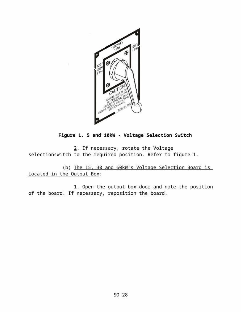
(a) The 5 and 10kW’s Voltage Selection Switch is Located Inside the Right Side Access Door:
1. Open the right side access door and note the position of the switch.
Figure 1. 5 and 10kW - Voltage Selection Switch
2. If necessary, rotate the Voltage selectionswitch to the required position. Refer to figure 1.
SO 23
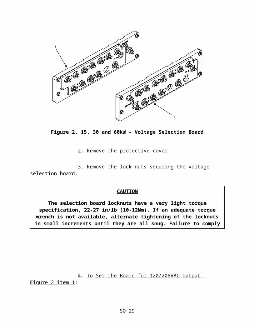
(b) The 15, 30 and 60kW’s Voltage Selection Board is Located in the Output Box:
1. Open the output box door and note the position of the board. If necessary, reposition the board.
Figure 2. 15, 30 and 60kW – Voltage Selection Board
2. Remove the protective cover.
3. Remove the lock nuts securing the voltage selection board.
CAUTION
The selection board locknuts have a very light torque specification, 22-27 in/lb (10-12Nm). If an adequate torque wrench is not available, alternate tightening of the locknuts in small increments until they are all snug. Failure to comply
will cause damage to the equipment.
SO 24
4. To Set the Board for 120/208VAC Output Figure 2 item 1:
a. Position the voltage selection moveable board to the left-side with the right side arrow pointing to 120/208 on the voltage selection stationary board.
b. Thread the 12 locknuts on the studs that secure the moveable board to the stationary board.
c. Torque the 12 locknuts to 22-27 in/lb (10-12 Nm).
NOTE
There will be one locknut and one stud that is not used, install the locknut on the empty stud for future use.
5. To Set the Board for 240/416VAC OutputFigure 2 Item 2:
a. Position the voltage selection moveable board to the right-side with the left side arrow pointing to 240/416 on the voltage selection stationary board. b. Place 11 locknuts on the studs that secure the moveable board to the stationary board.
c. Torque the 11 locknuts to 22-27 in/lb (10-12 Nm).
NOTE
There will be two locknuts and two studs that are not used, install the locknuts on the empty studs for future use.
NOTE
The first time the DCS is energized after changing the voltage selection board or switch, [Warning 3667: Voltage
Configuration Change] will be displayed on the DCS. Press the Fault Reset until the warning goes away.
SO 25
(3) Determine the Frequency Requirement. The output frequency of an AMMPS Mode 1 generator set can be set for 50 or 60Hz. Refer to the owner of equipment that is being powered or the equipment Technical Manual for the frequency requirement. To check the output frequency setting of a Mode 1 generator set:
(a) Turn on the main 24VDC breaker.
(b) Place the Engine Control Switch in the PRIME & RUN or PRIME & RUN AUX FUEL position.
(c) Note the Configuration displayed on the MAIN SCREEN, if necessary, change the output frequency set point. Perform the following.
NOTE
The frequency of Mode 1 generator sets cannot be selected unless the ECS is in the PRIME & RUN or PRIME & RUN AUX FUEL
position. (d) Press the [Adjustments] soft key, [Adjustment] screen 1 will display.
(e) Press the ◄ Previous + Next ► soft keys simultaneously for 2 seconds changes the display to [Adjustment] screen 2. Frequency Select will be highlighted.
(f) Press the select soft key, the current setting (50 or 60) will be displayed.
(g) Press the [+] or [-] soft key and the setting will change to (50 or 60).
(h) Press the [Accept] soft key, the Frequency Select and Frequency Adjust display will change to the new setting.
(i) Warning Code 3678. [Genset Frequency Changed] will be displayed on the DCS. Press the Fault Reset until the warning goes away.
(j) Place the Engine Control Switch in the OFF position.
(k) Turn off the main 24VDC breaker.
SO 26
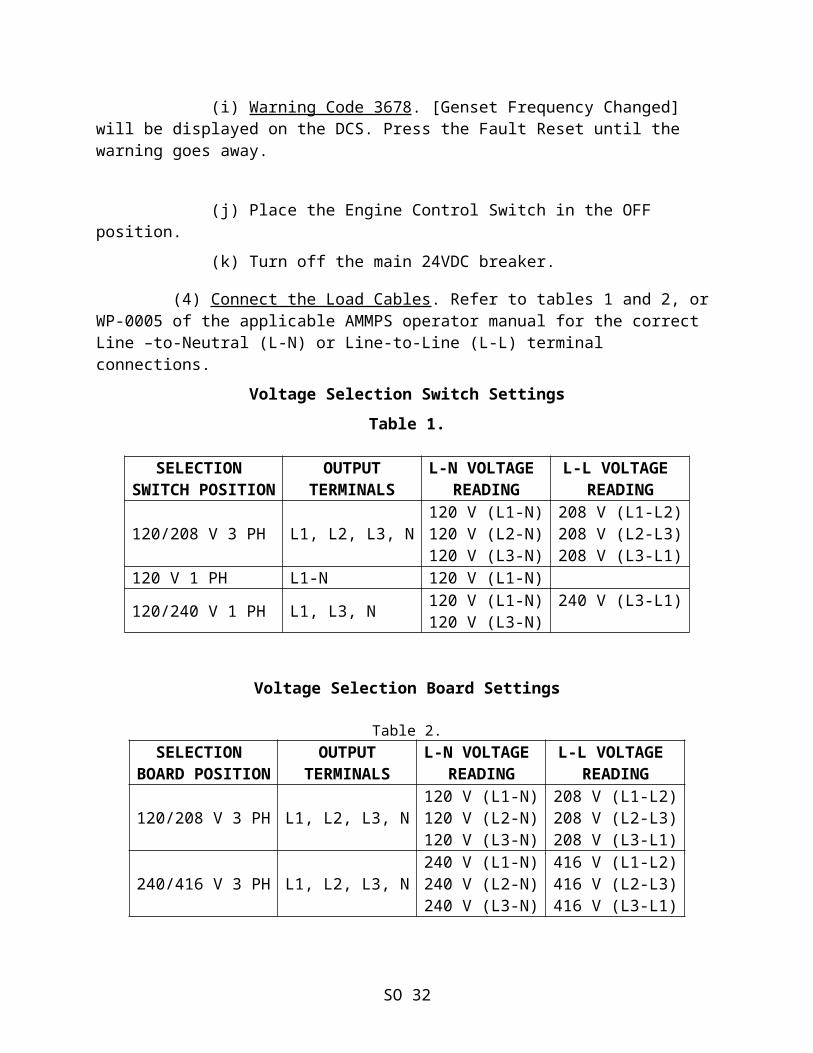
(4) Connect the Load Cables. Refer to tables 1 and 2, or WP-0005 of the applicable AMMPS operator manual for the correct Line –to-Neutral (L-N) or Line-to-Line (L-L) terminal connections.
Voltage Selection Switch Settings Table 1.
SELECTION SWITCH POSITION
OUTPUTTERMINALS
L-N VOLTAGE READING
L-L VOLTAGE READING
120/208 V 3 PH L1, L2, L3, N120 V (L1-N)120 V (L2-N)120 V (L3-N)
208 V (L1-L2)208 V (L2-L3)208 V (L3-L1)
120 V 1 PH L1-N 120 V (L1-N)
120/240 V 1 PH L1, L3, N 120 V (L1-N)120 V (L3-N)
240 V (L3-L1)
Voltage Selection Board Settings
Table 2.SELECTION
BOARD POSITIONOUTPUT
TERMINALSL-N VOLTAGE
READINGL-L VOLTAGE
READING
120/208 V 3 PH L1, L2, L3, N120 V (L1-N)120 V (L2-N)120 V (L3-N)
208 V (L1-L2)208 V (L2-L3)208 V (L3-L1)
240/416 V 3 PH L1, L2, L3, N240 V (L1-N)240 V (L2-N)240 V (L3-N)
416 V (L1-L2)416 V (L2-L3)416 V (L3-L1)
(5) Operation From an External Fuel Source. If operating from an external fuel source, connect the auxiliary fuel line to the fuel source and the fuel supply connection.
(6) Using an AMMPS Generator as a Fuel Source. If the generator set is to be used as a fuel source, connect the auxiliary fuel line to the fuel withdraw connection and the equipment that will be using the fuel.
SO 27
6. AMMPS START UP PROCEDURE. a. To P lac e the G enerator in O peration , Perform the Following Steps:
(1) Perform before PMCS.
(2) Place the DEAD CRANK SWITCH in Normal. (Inside the right side access door on all models except the 60kW which is inside the left side access door).
(3) Turn on main DC Circuit Breaker. (Inside the left side access door on all models except the 60kW which is inside the right side access door).
(4) Ensure the EMERGENCY STOP is not pushed in.
(5) Ensure BATTLESHORT switch is in the OFF position.
(6) Move the engine control switch to PRIME & RUN.
(7) Allow the fuel pump to complete priming of fuel injector pump before proceeding. Listen for the fuel pump to stop operating.
NOTE
Under normal operating conditions, the control panel display will take 4 sec or more to establish contact with the internal Display and Main Controller Boards. While contact is being
established, the screen display is gray. It will be indicated in the Mode and Status lines as: [Genset Mode: Unknown] and [Establishing Communications]. The length of time the screen
is either blank or gray depends on ambient temperature.
CAUTION
The default starting position for the UNIT PARALLEL switch is [UNIT]. If the DCS indicates the unit is in [PARALLEL], notify
field maintenance. Failure to comply will cause damage to equipment.
SO 28
(8) When the DCS displays [Genset Mode: Ready to Crank,] move the engine control switch to START and release; the DCS will initiate the start sequence and the engine control switch will return to PRIME & RUN. If using an auxiliary fuel source move the switch to PRIME & RUN AUX FUEL. The external fuel system will maintain the fuel tank level between 75 and 100%. (9) Allow the engine to operate without load for 5 min.
NOTE
It is recommended to warm up engine without load for 5 min. The load can be applied immediately if required.
(10) Observe the DCS main screen for proper phase, voltage and frequency. Adjust if necessary.
(11) Close the load contactor by pushing the AC CIRCUIT INTERRUPT switch on the control panel once.
(12) Observe the main screen display for [Contactor Closed] which shows that the generator set is now supplying power to the load.
7. AMMPS SHUTDOWN PROCEDURES. a. When we are D one P roviding P ower and are R eady to S hut D own the AMMPS Generator, Perform the Following Steps :
(1) Push AC CIRCUIT INTERRUPT switch to place generator contactor in [CONTACTOR OPEN] position.
(2) Verify CONTACTOR OPEN is displayed.
(3) Allow generator set to operate for 5 min with no load applied.
NOTE
The engine can be shut down immediately after the load is removed. It is preferred that a cool down period of 5 min be
allowed before engine shut down.
(4) Place engine control switch in OFF position.
(5) Place DEAD CRANK SWITCH in OFF position.
SO 29
(6) Push in EMERGENCY STOP.
(7) Turn main DC circuit breaker to OFF/TRIP.
(8) Perform all After PMCS.
8. OPERATION WITH REMOTE MONITORING.
a. The AMMPS Generator Sets Provide Limited Remote Operation Capabilities. The intent of the remote operation capability is to permit the operator to monitor more than one unit at the same time and to be sheltered from severe environmental conditions. Remote operation provides the ability to perform the following from a distance up to 250 ft:
(1) Monitor the Operational Status of the Generator Set on a PC Screen to Include:
(a) Warning codes.
(b) Fault codes.
(c) Operational Parameters.
(2) Set and release BATTLESHORT operation (By order of appropriate authority (Battalion/Squadron commander or above).
(3) Execute an emergency stop.
NOTE
Loss of signal between the remote monitoring site and generator set will release the BATTLESHORT setting at the
generator set.
b. Remote Operation Requirements:
(1) Compatible PC with; Windows 2000, Windows XP, Windows Vista, or Windows 7 32-bit operating system, Internet Explorer 5.5 or above installed on the system.
(2) Cable, remote – NSN 6110-01-596-7719.
(3) Convertor – RS 485 to RS 232.
SO 30
NOTE
The PC, and remote cable do not come with the generator set and must be ordered separately.
c. To Utilize the Remote Operation Capability Perform the Following:
(1) Perform all before operation PMCS.
(2) Start generator set.
(3) Perform all during operation PMCS.
(4) Ensure unit is operating at requested parameters.
(5) Insert remote cable (Figure 3, Item 2) into REMOTE connector (Figure 3, Item 2) on DCS.
FIGURE 3. (6) Connect the other end of the remote cable (Figure 3, Item 3) to the RS-485 side of the converter; connect the RS 232 side of the convertor to the PC COM Port 1 of a compatible PC (Figure 3, Item 1).
SO 31
(7) Initialize the PC.
(8) Monitoring Screen. Observe the remote monitoring screen for Warnings/Faults and the Parameter indicators to ensure they remain in the proper operating range:
(a) Genset and Bus voltages.
(b) Genset current.
(c) Genset and Bus Frequency.
(d) Power.
(e) Fuel level.
(f) Battery voltage and current.
(g) Oil pressure.
(h) Coolant temperature.
(9) Enable or disable the [Battle Short], as required by proper authority by placing PC cursor over the [Battle ShortCommand] symbol and clicking the mouse or pressing [Enter] on the keyboard.
(ON SLIDE #53)
SO 32
CAUTION
Do not allow the generator set to operate with any Warnings or Faults displayed unless specifically required to do so by
proper authority. Shut down the generator set using the remote emergency stop function or by the normal shutdown procedure. Failure to comply will cause damage to the generator set. Troubleshoot any Warnings or Faults IAW WP 0010 of the
applicable TM.
NOTE
[Battle Short Command] position will display [OFF] when the battle short is inactive and [ON] when active. The remote battle short command is independent of the battle short
command on the DCS. It is possible to turn on the battle short from the DCS. In this case, the [Battle Short] status field
will change to [Active] and the [Battle Short Command] position will remain in the [OFF] position.
(10) Enable or disable the [Emergency Stop] as required by placing PC cursor over the [Emergency Stop] command symbol and clicking the mouse or pressing [Enter] on the keyboard. The [Emergency Stop] status display will show either [Stopped] or [Not Stopped]. The [Emergency Stop] command symbol will display either [OFF] or [ON].
SO 33
NOTE
Both the remote [Emergency Stop] and the DCS EMERGENCY STOP switch must be [OFF] to restart the engine while the remote
monitor is active.
REFERENCE: REFERENCE#
Ground Equipment Record Procedures TM 4700-15/1_
Operator and Field Maintenance Manual TM 10155A-OI/1A(Including Repair Parts and Special Tools List) for 3kW Tactical Quiet Generator Set MEP-831A (60Hz) and MEP-832A (400Hz)
Operator's Manual for Generator Set, Skid TM 11783A/11784A-OIMounted 10kW Advanced Medium Mobile PowerSources (AMMPS) MEP-1040 50/60Hz andMEP-1041 400Hz
Operator's Manual for Generator Set, Skid TM 11773A-OIMounted 15kW Advanced Medium Mobile PowerSources (AMMPS) MEP-1050 50/60Hz andMEP-1051 400Hz
Operator's Manual for Generator Set, Skid TM 09246C/11776A-OIMounted 30kW Advanced Medium Mobile PowerSources (AMMPS) MEP-1060 50/60Hz andMEP-1061 400Hz
Operator's Manual for Generator Set, Skid TM 09292B-OI/3Mounted 5kW Advanced Medium Mobile PowerSources (AMMPS) MEP-1030 50/60Hz andMEP-1031 400Hz
Operator's Manual for Generator Set, Skid TM 09244C/09245C-OIMounted 60kW Advanced Medium Mobile PowerSources (AMMPS) MEP-1070 50/60Hz andMEP-1071 400Hz
Operator's Manual for Generator Set, Skid TM 07464C-10/1Mounted, Tactical Quiet, 100kW, 50/60Hz,MEP-807A
Operator's Manual for Generator Set, Skid TM 09247A/09248A-Mounted, Tactical Quiet, 10kW, 10/1MEP-803A/MEP-813A
Operator, Field, and Sustainment TM 09244B/09245B-Maintenance Manual for Generator Set, Skid OI/1Mounted, Tactical Quiet, 60kW, 50/60Hz MEP-806B and 400Hz MEP-816B
SO 34
Operator, Unit, Direct Support and General TM 09249B/09246B-Support Maintenance Manual for Generator 14/1Set, Skid Mounted, Tactical Quiet, 30kW, 50/60 and 400Hz, MEP-805B/MEP-815B
SO 35
SO 36