Embed Size (px)
Citation preview
Ammonia as hydrogen carrier for transportation;
investigation of the ammonia exhaust gas fuel
reforming5
Wentao Wang a, Jose M. Herreros a, Athanasios Tsolakis a,*, Andrew P.E. York b
a School of Mechanical Engineering, University of Birmingham, Edgbaston B15 2TT, UKb Johnson Matthey Technology Centre, Blount’s Court, Sonning Common, Reading RG4 9NH, UK
a r t i c l e i n f o
Article history:
Received 25 March 2013
Received in revised form
21 May 2013
Accepted 26 May 2013
Available online 24 June 2013
Keywords:
Ammonia
Hydrogen
Reforming
Diesel
Emissions
a b s t r a c t
In this paper we show, for thefirst time, thefeasibility of ammonia exhaust gas reforming as
a strategy for hydrogen production used in transportation. The application of the reforming
process and the impact of the product on diesel combustion and emissions were evaluated.
The research was started with an initial study of ammonia autothermal reforming (NH 3 e
ATR) that combined selective oxidation of ammonia (into nitrogen and water) and ammonia
thermal decomposition overa rutheniumcatalystusingair as theoxygen source. Theair was
later replaced by real diesel engine exhaust gas to provide the oxygen needed for the
exothermic reactions to raise the temperature and promote the NH 3 decomposition. The
main parameters varied in the reforming experiments are O2 /NH3 ratios, NH3 concentration
in feed gas and gas e hourly e space e velocity (GHSV). The O2 /NH3 ratio and NH3
concentration were the key factors that dominated both the hydrogen production
andthe reforming processefficiencies: by applying an O2 /NH3 ratio ranged from 0.04to 0.175,
2.5e3.2 l/min of gaseous H2 production was achieved using a fixed NH3 feed flow of 3 l/min.
The reforming reactor products at different concentrations (H2 and unconverted NH3)
were then added into a diesel engine intake. The addition of considerably small amount of
carbon e free reformate,i.e. represented by 5% of primary diesel replacement, reduced quite
effectively the engine carbon emissions including CO2, CO and total hydrocarbons.
Copyright ª 2013, The Authors. Published by Elsevier Ltd. All rights reserved.
1. Introduction
The use of hydrogen in internal combustion engines has long
been believed to be beneficial in terms of emissions reduction
such as HCs, CO, CO2 and particulate emissions [1,2]. Addi-
tionally, its utilisation has been proven to be effective in
enhancing automotive aftertreatment performance especially
at low engine exhaust gas temperatures [3,4]. However, its low
volumetric energy density and its high transportation cost
make on e board hydrogen storage difficult [5]. Previous
studies have shown that H2 can be produced by means of
hydrocarbon reforming [6,7]. This method can be also adopted
for the purpose of on-board reforming of hydrocarbon fuel i.e.,
using recovered heat and oxidant from exhaust gases for
5 This is an open-access article distributed under the terms of the Creative Commons Attribution-NonCommercial-No DerivativeWorks License, which permits non-commercial use, distribution, and reproduction in any medium, provided the original author andsource are credited.
* Corresponding author. Tel.: þ44 (0) 121 414 4170; fax: þ44 (0) 121 414 7484.E-mail address: [email protected] (A. Tsolakis).
Available online at www.sciencedirect.com
j o u r n a l h o m e p a g e : w w w . e l s e v i er . c o m / l o c a t e / he
i n t e r n a t i o n a l j o u r n a l o f h y d r o g e n e n e r g y 3 8 ( 2 0 1 3 ) 9 9 0 7 e9 9 1 7
0360-3199/$ e see front matter Copyright ª 2013, The Authors. Published by Elsevier Ltd. All rights reserved.http://dx.doi.org/10.1016/j.ijhydene.2013.05.144
driving fuel reforming. This is considered as a potential so-
lution to deal with the hydrogen storage issue [8]. Recently,
increasing numbers of studies have shown that hydrogen
production can be implemented through ammonia thermal
decomposition for small scale fuel cell power systems [9e12].
Decomposition of ammonia is by definition COx free, and CO2
yielded during ammonia synthesis can be sequestrated on-
site at the production plants [13e15]. Thus using ammonia
as a hydrogen source is potentially an alternative to the con-
ventional hydrocarbon reforming and makes the on-board
hydrogen production free of COx.
Ammonia has been overlooked in the past for vehicular
applications; both as a fuel and a hydrogen carrier. In general,
its low heating value on mass basis indicates ammonia has
less energy for combustion than conventional fossil fuels i.e.
gasoline and diesel. However, the stoichiometric air e fuel
ratio for ammonia is much lower compared to diesel fuel. This
results in ammonia having an LHV of 2.64 MJ per kg of stoi-
chiometric mixture, which is comparable to that of diesel
(2.77 MJ/kg) [16]. Nonetheless, because of ammonia’s relatively
high auto-ignition temperature (651 C compared to 254 C for
diesel), complete in-cylinder combustion of ammonia is
difficult, which leads to significant emission of NH3 [17]. It
should be noticed that 1 mol of ammonia contains 1.5 mol of
hydrogen, which is 17.8% by weight or 108 kg e H2 /m3
embedded in liquid ammonia at 20 C. Comparing this to the
most advanced hydrogen storage systems, e.g. metal hy-
drides, which store H2 up to 25 kg/m3, the advantage of
ammonia in carrying hydrogen per unit volume is significant
[18]. Therefore, using hydrogen extracted from ammonia ap-
pears to be more beneficial than combusting ammonia
directly in an IC engine. Zamfirescu [13] in a recent study
compared NH3 with other common fuels such as gasoline,
CNG, LPG and methanol, showing that NH3 is competitive to
these fuels in terms of gravimetric, volumetric and energetic
costs (see in Table 1). Based on this study, a further compari-
son between each fuel’s molar hydrogen carrying ability per
unit mass, volume and cost can be made, which indicates
ammonia is a more affordable hydrogen carrier, Table 2.
In addition to that, the storage, distribution and trans-
portation infrastructure of ammonia is established [19], with
100million tonnesof ammonia being deliveredeach year. Thus
the existing production and handling system of ammonia
reveal a great potential in expanding its usage to vehicle ap-
plications as a sustainable fuel [20]. Ammonia hasalreadybeen
applied but in the form of urea on today’s heavy duty diesel
vehicles for catalytic aftertreatment systems for NOx reduc-
tion. Therefore special technology and regulation for safe
storage of ammonia on passenger cars should be developed or
an additional step of thermo-catalytic conversion of urea to
ammonia should be applied as shown in the literature [21].
As reported in earlier studies, a temperature higher than
500 C is required for catalytic NH3 decomposition in order to
achieve stable NH3 conversion and high H2 production
[5,22e24]. However, for on-board applications the exhaust gas
temperature of a typical diesel engine is only in the range of
150e400 C. Thus a mechanism is required to raise the tem-
perature of the gas stream for the purpose of on-board NH3
decomposition. The new approach is to apply the same prin-
ciple as that of autothermal reforming (ATR) and exhaust gas
fuel reforming,where part of the fuel is oxidised to provide the
energy needed by a subsequent fuel reforming mechanism to
produce H2. If sufficient ammonia oxidation takes place, the
endothermic ammonia decomposition can be self e sustain-
ing using the provided heat.
The expected selective catalytic oxidation of ammonia
(into nitrogen and water) and NH3 decomposition reactions
are expressed by Eqs. (1) and (2), respectively. The desired
combination is shown by Eq. (3).
4NH3 þ 3O2 ¼ 6H2O þ 2N2; DHr ¼ 1260kJ=mol (1)
2NH3 ¼ 3H2 þ N2; DHr ¼ þ46kJ=mol (2)
NH3 þ xO2 ¼ 2xH2O þ ð1:5 2xÞH2 þ 0:5N2; x < 0:75 (3)
In Eq. (3), x represents the O2 /NH3 molar ratio, a parameter
which controls the intensity of the exothermic portion in the
overall process, which can in turn determine the stoichio-
metric yield of hydrogen. In the current study, air is used to
provide the oxygen needed by the reaction and is referred NH3
e ATR throughout. Furthermore, if diesel engine exhaust is
used to provide the O2, and part of the exhaust heat is
recovered as a primary energy source for the reaction then the
NH3 e ATR is transformed into NH3 exhaust gas reforming.
To summarise, in this research, three different experiments
were performed and analysed. Firstly, the catalytic NH3
decomposition was studied at different temperatures. Sec-
ondly, the oxidative mechanism of ammonia and NH3 decom-
position were combined enabling NH3 e ATR and NH3 exhaust
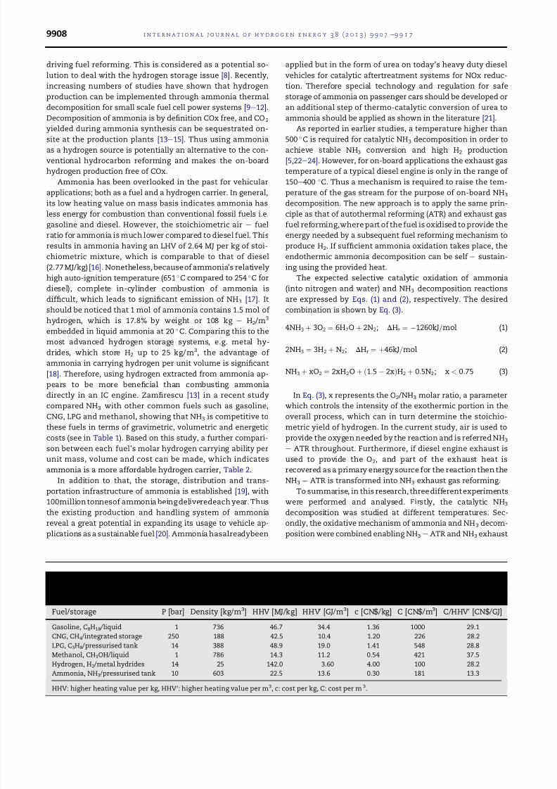
Table 1 e Comparison of ammonia with other fuels including hydrogen (adapted from C. Zamfirescu and I. Dincer,Ammonia as a green fuel and hydrogen source for vehicular applications. Fuel Processing Technology, 2009. 90(5): p.729e737).
Fuel/storage P [bar] Density [kg/m3] HHV [MJ/kg] HHV0 [GJ/m3] c [CN$/kg] C [CN$/m3] C/HHV0 [CN$/GJ]
Gasoline, C8H18 /liquid 1 736 46.7 34.4 1.36 1000 29.1
CNG, CH4 /integrated storage 250 188 42.5 10.4 1.20 226 28.2
LPG, C3H8 /pressurised tank 14 388 48.9 19.0 1.41 548 28.8
Methanol, CH3OH/liquid 1 786 14.3 11.2 0.54 421 37.5
Hydrogen, H2 /metal hydrides 14 25 142.0 3.60 4.00 100 28.2
Ammonia, NH3 /pressurised tank 10 603 22.5 13.6 0.30 181 13.3
HHV: higher heating value per kg, HHV 0: higher heating value per m3, c: cost per kg, C: cost per m 3.
i n t e r n a t i o n a l j o u r n a l o f h y d r o g e n e n e r g y 3 8 ( 2 0 1 3 ) 9 9 0 7 e9 9 1 79908
gas reforming. Finally, the yielded reformate (H2 and uncon-
verted NH3) was sent back to a diesel engine to examine how a
reforming system affects the combustion process and
emissions.
2. Experimental and methodology
2.1. Catalyst
In this study, a ruthenium catalyst was chosen, given its ac-
tivity in both ammonia oxidation [25] and decomposition
[22,26]. The catalyst was provided by Johnson Matthey and
coated on 1/8 inch OD g-Al2O3 pellet supports with a loading
ratio of 2% by weight.
2.2. Test setup
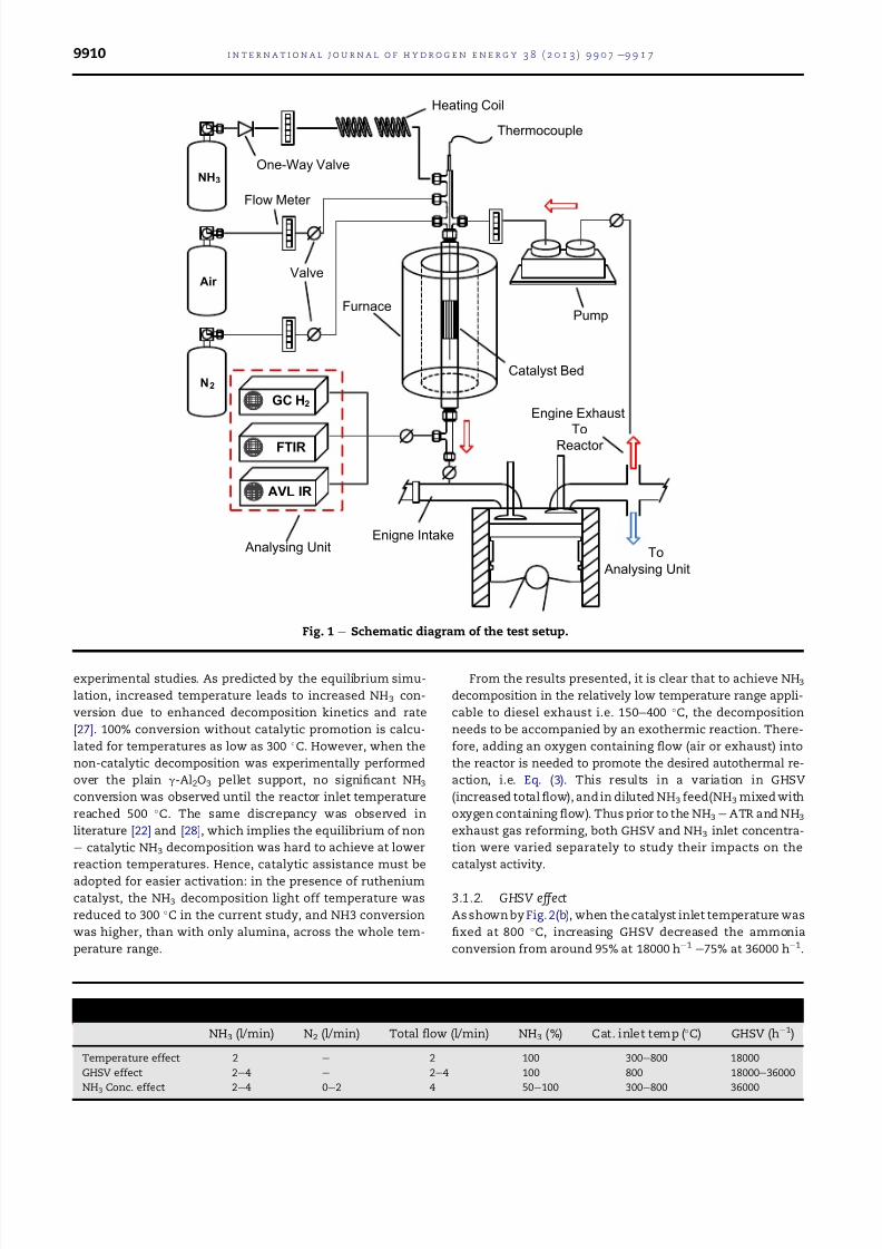
All reforming tests were carried out in a laboratory reforming
reactor, which is shown in Fig.1. Thecatalystwas loaded inside
a stainless steel reactor (15 mm in diameter) that was held
vertically within a tube furnace. At the centre of the catalyst
bed, a tubular sheath was fitted, which was made from a
stainless steel tube with one end sealed. In order to investigate
the process’s thermal behaviour, a k-type thermocouple was
inserted into the sheath to record the reaction temperature
along the catalyst bed. Ammonia was supplied by a gas bottle
and injected into the reactor, controlled by a flow metre. Ni-
trogen andair were introduced at separate inlets of the reactor.
Before each experiment, inert nitrogen was initially introduced
through the reactor to make sure the temperature gradient
along the catalyst bed was minimised. For ammonia exhaust
gas reforming part of the diesel engine exhaust was extracted
from the exhaust manifoldand was introducedinto the reactor.
The exhaust flow rate was controlled to meet different O2 /NH3
ratios. The product gas was analysed downstream of the
reactor. Hydrogen was measured using an HP 5890 series II gas
chromatograph (GC) with thermal conductivity detector (TCD)
sensor and signal integrator, using argon as the carrier gas. O2
was measured using an AVL DIGAS 440 non-dispersive IR
analyser.NH3and allother nitrogen containedspecies (NO,N2O
and NO2) were recorded by FTIR (Fourier Transform Infrared
Spectroscopy), MKS MultiGas 2030. For ammonia exhaust gas
reforming, FTIR was also used to record species such as CO,CO2
and total hydrocarbons emitted from the engine.
2.3. Test procedure
The catalyst’s activity in ammonia decomposition was studied
first. Test conditions including catalyst inlet temperature, gas-
hourly-space-velocity (GHSV) and catalyst inlet NH3 concen-
trations were varied (Table 3). Following that NH3 e ATR was
performed at two catalyst loadings: 8 g and 16 g, whereas NH3
exhaust gasreforming was studied over the16 g catalyst only. A
NH3 flow of 3 l/min was used throughout the NH3 e ATR and
Exhaust gasreforming.Air and engineexhaustwere added into
the NH3 flow at varying O2 /NH3 ratios and NH3 concentrations
(Table 4).A400 C reactor temperature was maintained using a
furnace to simulate the diesel exhaust temperature at mid e
highload operation to givethe reactor the primary heat. Finally,
the reformer system was connected in a closed loop configu-
ration (Fig. 1). Reformates with different compositions were
recirculated back to the engine intake while the engine was
operated at a constant load of 4 bar IMEP and 1500 rpm. Engine
performance and emissions with reformate addition were
recorded. The engine exhaust composition for the diesel base-
linecondition (no reformate addition) is summarised in Table 5.
2.4. Reforming process efficiency
The process efficiency h was defined as the lower combustion
enthalpy rate (kJ/sec) of the product stream divided by the
lower combustion enthalpy rate (kJ/sec) of the reactant
stream. Here, the product stream can be either defined as the
produced H2 alone or H2 combined with any unconverted NH3
(both can be considered as fuels to the engine). Thus two ef-
ficiencies, namely hydrogen efficiency and reforming process
efficiency can be adopted to evaluate the reforming perfor-
mance. These are defined by Eqs. (4) and (5) below:
hH2ð%Þ ¼
LCVH2 _mH2
LCVNH3 _mNH3
100% (4)
href ð%Þ ¼
LCVH2 _mH2
þ
LCVNH3 _mNH3
LCVNH3 _mNH3
100% (5)
where LCVH2 and LCVNH3 are the lower calorific values of the
produced H2 and the gas feed NH3, whereas _mNH3 and _mH2 are
the mass flow rates of NH3 and H2 respectively.
3. Results and discussion
3.1. NH3 decomposition over Ru e Al2O3 catalyst
3.1.1. Temperature effect
Fig. 2(a) depicts the decomposition of pure NH3 at different
reactor inlet temperatures. In addition to experimental re-
sults, an equilibrium calculation for NH3 decomposition was
made using an STANJAN equilibrium model (v 3.91, Stanford
University) at the same temperatures as those of the
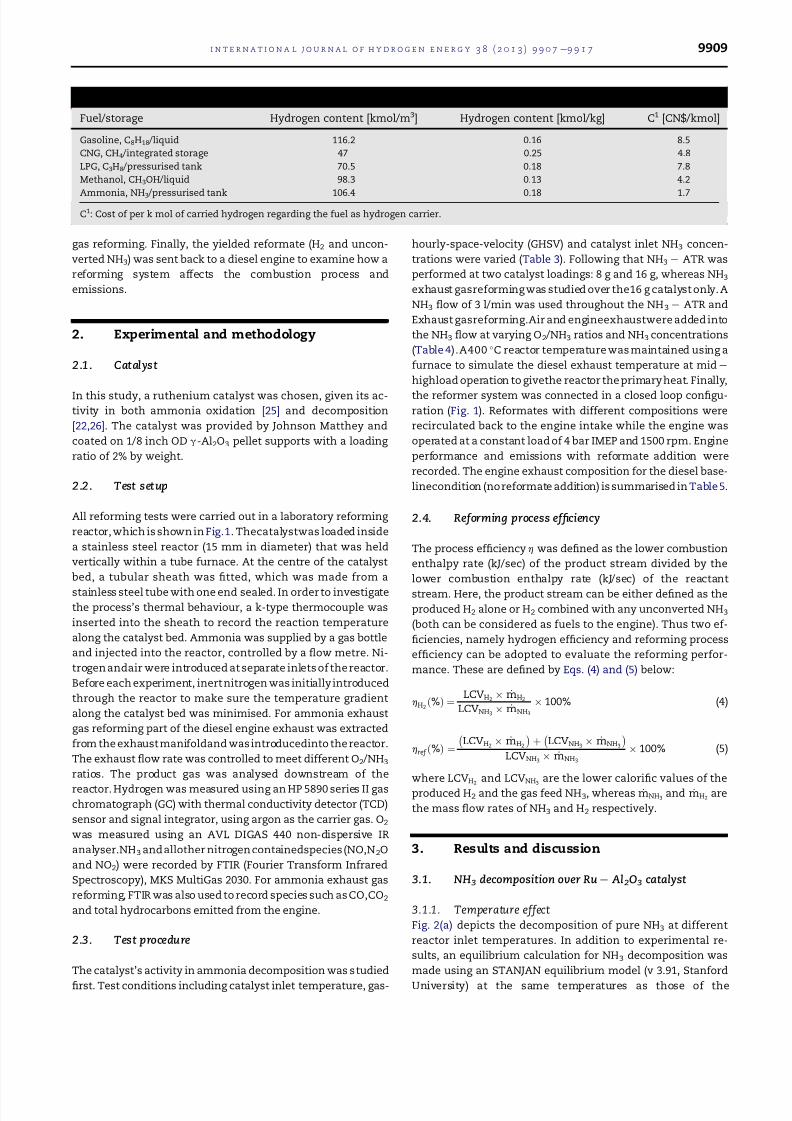
Table 2 e Further comparison of ammonia with other fuels based on the data listed in Table 1.
Fuel/storage Hydrogen content [kmol/m3] Hydrogen content [kmol/kg] C1 [CN$/kmol]
Gasoline, C8H18 /liquid 116.2 0.16 8.5
CNG, CH4 /integrated storage 47 0.25 4.8
LPG, C3H8 /pressurised tank 70.5 0.18 7.8
Methanol, CH3OH/liquid 98.3 0.13 4.2
Ammonia, NH3 /pressurised tank 106.4 0.18 1.7
C1: Cost of per k mol of carried hydrogen regarding the fuel as hydrogen carrier.
i n t e r n a t i o n a l j o u r n a l o f h y d r o g e n e n e r g y 3 8 ( 2 0 1 3 ) 9 9 0 7 e9 9 1 7 9909
experimental studies. As predicted by the equilibrium simu-
lation, increased temperature leads to increased NH3 con-
version due to enhanced decomposition kinetics and rate
[27]. 100% conversion without catalytic promotion is calcu-
lated for temperatures as low as 300 C. However, when the
non-catalytic decomposition was experimentally performed
over the plain g-Al2O3 pellet support, no significant NH3
conversion was observed until the reactor inlet temperature
reached 500 C. The same discrepancy was observed in
literature [22] and [28], which implies the equilibrium of non
e catalytic NH3 decomposition was hard to achieve at lower
reaction temperatures. Hence, catalytic assistance must be
adopted for easier activation: in the presence of ruthenium
catalyst, the NH3 decomposition light off temperature was
reduced to 300 C in the current study, and NH3 conversion
was higher, than with only alumina, across the whole tem-
perature range.
From the results presented, it is clear that to achieve NH3
decomposition in the relatively low temperature range appli-
cable to diesel exhaust i.e. 150e400 C, the decomposition
needs to be accompanied by an exothermic reaction. There-
fore, adding an oxygen containing flow (air or exhaust) into
the reactor is needed to promote the desired autothermal re-
action, i.e. Eq. (3). This results in a variation in GHSV
(increased totalflow), and in diluted NH3 feed(NH3 mixed with
oxygen containing flow). Thus prior to the NH3 e ATR and NH3
exhaust gas reforming, both GHSV and NH3 inlet concentra-
tion were varied separately to study their impacts on the
catalyst activity.
3.1.2. GHSV effect
As shown by Fig. 2(b), when the catalyst inlet temperature was
fixed at 800 C, increasing GHSV decreased the ammonia
conversion from around 95% at 18000 h1 e75% at 36000 h1.
Table 3 e Test conditions for NH3 decomposition.
NH3 (l/min) N2 (l/min) Total flow (l/min) NH3 (%) Cat. inlet temp (C) GHSV (h1)
Temperature effect 2 e 2 100 300e800 18000
GHSV effect 2e4 e 2e4 100 800 18000e36000
NH3 Conc. effect 2e4 0e2 4 50e100 300e800 36000
Valve
NH3
Air
N2
GC H2
Thermocouple
Flow Meter
One-Way Valve
Heating Coil
Catalyst Bed
Pump
Engine Exhaust
To
Reactor
To
Analysing Unit
Analysing Unit
Furnace
AVL IR
FTIR
Enigne Intake
Fig. 1 e Schematic diagram of the test setup.
i n t e r n a t i o n a l j o u r n a l o f h y d r o g e n e n e r g y 3 8 ( 2 0 1 3 ) 9 9 0 7 e9 9 1 79910
This is due to reduced residence time of the NH3 over the
catalyst at the region where the endothermic reaction is active
(i.e. will be described in 3.2 sections) resulting in lowered
decomposition efficiencies [29].
3.1.3. NH3 concentration effect
Fig. 2(c) illustrates the ammonia conversion as a function of
temperature and ammonia concentration in the feed gas.
Instead of using pure NH3, nitrogen was co-fed into the reac-
tant stream. The total inlet flow was kept constant at 4 l/min,
resulting in a GHSV of 36000 h1. It is shown that as the inlet
ammonia concentration reduced, the NH3 conversion
increased for a fixed temperature. In earlier studies, hydrogen
was found to be inhibitive to NH3 decomposition. This is
because the NH3 decomposition is limited by a chemical
equilibrium between the forward and reverse reactions. A
high H2 partial pressure and a low reaction temperature will
contribute to a retarded forward rate of the NH3 decomposi-
tion [30e34]. This explains the shift of NH3 conversion to
higher temperatures as the ammonia concentration in the
feed gas increased. When the NH3 concentration is higher in a
constant reactant flow, the amount of H2 produced is higher
and thus the inhibition is more pronounced [5]. The other
product of the reaction, N2, is seen to have negligible influence
on the forward rate [5,30,32]. In the current study, nitrogen
behaved mainly as an inert gas, which diluted the inlet NH3 to
lower concentrations. In this case, reactions with lower inlet
NH3 concentrations show similar conversions at lower tem-
peratures as those with high concentrations of NH3.
3.2. Combined NH3 oxidation and decomposition: NH3 e
ATR and NH3 exhaust gas reforming
3.2.1. Temperature profiles
In Fig. 3 (a) e (c), the thermal behaviour of the combined re-
action (Eq. (3)) at different O2 /NH3 ratios was reflected by the
temperature profile along the catalyst bed. For both NH3 e ATR
and NH3 exhaust gas reforming, the reactor temperature
increased abruptly near the catalyst inlet and declined
thereafter. The temperature rise at catalyst inlet was due to
NH3 oxidation (Eq. (1)); the decrease was associated with the
endothermic ammonia decomposition (Eq. (2)) and thereactor
heat losses [8]. Such observation is in agreement with previ-
ous researches [35,36], where mechanisms of exothermic and
endothermic were combined and performed.
In general, by varying the O2 /NH3 ratio from 0.04 to 0.175 in
both NH3 e ATR and exhaust gas reforming, the temperature
increase along the catalyst bed was enhanced, meaning
increased oxygen input promoted the exothermic reaction. In
addition to that, the higher the O2 /NH3 ratio, the larger the
temperature drop in the endothermic area, indicating
improved NH3 decomposition along the catalyst bed (this will
be confirmed by increased hydrogen formation shown in the
next section).
For NH3 e ATR (Fig. 3(a) and (b)), similar temperature in-
creases were observed over the 8 g and 16 g catalyst beds.
However, compared to the 8 g catalyst bed, the temperature
decrease was found to be more pronounced at the16 g catalyst
at each tested O2 /NH3 ratio. This is caused by the greatly
increased residence time over the 16 g catalyst strengthening
the NH3 decomposition through a better use of the available
enthalpy [29].
When NH3 e exhaust mixtures were introduced into the
16 g catalyst, the rise in temperature profiles (Fig. 3(c)) were
slightly weakened at each O2 /NH3 condition compared to
those for the tests with air. As the engine exhaust contains
only 10e15% oxygen by volume, the flow of the exhaust
required to maintain the same O2 /NH3 ratio was increased
from that of the air, and so was the GHSV (Table 4). The main
diesel exhaust gas components (e.g. CO2 and H2O) are known
as heat absorbers due to their relatively large specific heat
capacities [37]. Therefore, the temperature decrease in the
reactor could be associated with the heat absorption of those
species.
3.2.2. NH3 conversion and H2 production
The NH3 conversion at different O2 /NH3 ratio is depicted in
Fig. 4(a) for NH3 e ATR over the 8 g and 16 g catalysts. The
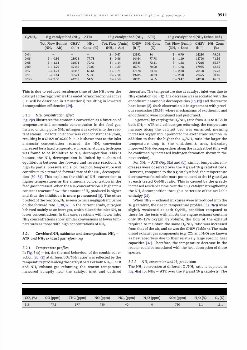
Table 4 e Test conditions for NH3 e ATR and NH3 exhaust gas reforming.
O2 /NH3 8 g catalyst bed (NH3 e ATR) 16 g catalyst bed (NH3 e ATR) 16 g catalyst bed (NH3 Exhst. Ref.)
Tot. Flow (l/min)(NH3 þ Air)
GHSV(h1)
NH3
Conc. (%)Tot. Flow (l/min)
(NH3 þ Air)GHSV(h1)
NH3 Conc.(%)
Tot. Flow (l/min)(NH3 þ Exh)
GHSV(h1)
NH3 Conc.(%)
0.04 e e e 3 þ 0.67 13392 84 3 þ 0.79 14230 79.05
0.06 3 þ 0.86 28928 77.78 3 þ 0.86 14464 77.78 3 þ 1.19 15720 71.56
0.08 3 þ 1.14 31071 72.41 3 þ 1.14 15535 72.41 3 þ 1.58 17210 65.37
0.09 3 þ 1.29 32142 70.00 3 þ 1.29 16071 70.00 3 þ 1.78 17955 62.65
0.12 3 þ 1.71 35357 63.64 3 þ 1.71 17678 63.64 3 þ 2.38 20190 55.72
0.15 3 þ 2.14 38571 58.33 3 þ 2.14 19285 58.33 3 þ 2.98 22425 50.16
0.175 3 þ 2.50 41250 54.55 3 þ 2.50 20625 54.55 3 þ 3.47 24288 46.32
Table 5 e Engine exhaust composition at 4 bar IMEP and 1500 rpm.
CO2 (%) CO (ppm) THC (ppm) NO (ppm) NO2 (ppm) N2O (ppm) NOx (ppm) H2O (%) O2 (%)
5.3 127.5 577 750 40 0 790 5.1 15.1
i n t e r n a t i o n a l j o u r n a l o f h y d r o g e n e n e r g y 3 8 ( 2 0 1 3 ) 9 9 0 7 e9 9 1 7 9911

Fig. 2 e NH3 decomposition over Ru e Al2O3 catalyst: (a) 2 l/min (GHSV [ 18000 hL1 ) of pure ammonia decomposed at
different temperatures, (b) 2e4 l/min of pure ammonia decomposition at different GHSV, and (c) ammonia conversion at
different NH3 concentrations in the NH3 e N2 mixtures and temperatures.
Fig. 3 e Temperature profiles: (a) and (b) temperature profiles of NH3 - ATR over 8 g and 16 g catalyst beds (c) temperature
profiles of NH3 exhaust gas reforming over 16 g catalyst bed.
i n t e r n a t i o n a l j o u r n a l o f h y d r o g e n e n e r g y 3 8 ( 2 0 1 3 ) 9 9 0 7 e9 9 1 79912
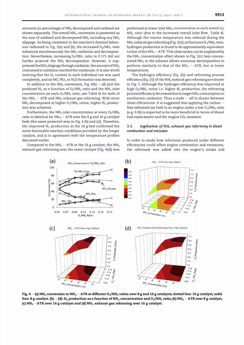
amounts (in percentage) of NH3 decomposed and oxidised are
shown separately. The overall NH3 conversion is presented as
the sum of oxidised and decomposed NH3 excluding any NH3
slippage. As being consistent to the reaction’s thermal behav-
iour indicated in Fig. 3(a) and (b), the increased O2 /NH3 ratio
enhanced simultaneously the NH3 oxidation and decomposi-
tion. Nevertheless, increasing O2 /NH3 ratio to 0.175 did not
further promote the NH3 decomposition. However, it sup-
pressed theNH3 slippage through oxidation: the amount of NH3
consumed in oxidation reached the maximum. It is also worth
noticing that the O2 content in each individual run was used
completely, and no NO, NO2 or N2O formation was detected.
In addition to the NH3 conversion, Fig. 4(b) e (d) plot the
produced H2 as a function of O2 /NH3 ratio and the NH3 inlet
concentration (at each O2 /NH3 ratio, see Table 4) for both of
the NH3 e ATR and NH3 exhaust gas reforming. With more
NH3 decomposed at higher O2 /NH3 ratios, higher H2 produc-
tion was achieved.
Furthermore, the NH3 inlet concentration at every O2 /NH3
ratio is identical for NH3 e ATR over the 8 g and 16 g catalyst
beds (the same projected area in Fig. 4 (b) and (c)). Therefore,
the improved H2 production at the 16 g bed confirmed the
more favourable reaction conditions provided by the longer
catalyst, and is in agreement with the temperature profiles
discussed earlier.
Compared to the NH3 e ATR at the 16 g catalyst, the NH3
exhaust gas reforming over the same catalyst (Fig. 4(d)) was
performed at lower inlet NH3 concentration at each tested O2 /
NH3 ratio (due to the increased overall inlet flow, Table 4).
Although the reactor temperature was reduced during the
NH3 exhaust gas reforming (Fig. 3(c)),atthesameO2 /NH3 ratio,
hydrogen production is found to be approximately equivalent
tothat ofthe NH3 e ATR. This observation can be explained by
the NH3 concentration effect shown in Fig. 2(c): less concen-
trated NH3 in the exhaust allows ammonia decomposition to
perform similarly to that of the NH3 e ATR, but at lower
temperatures.
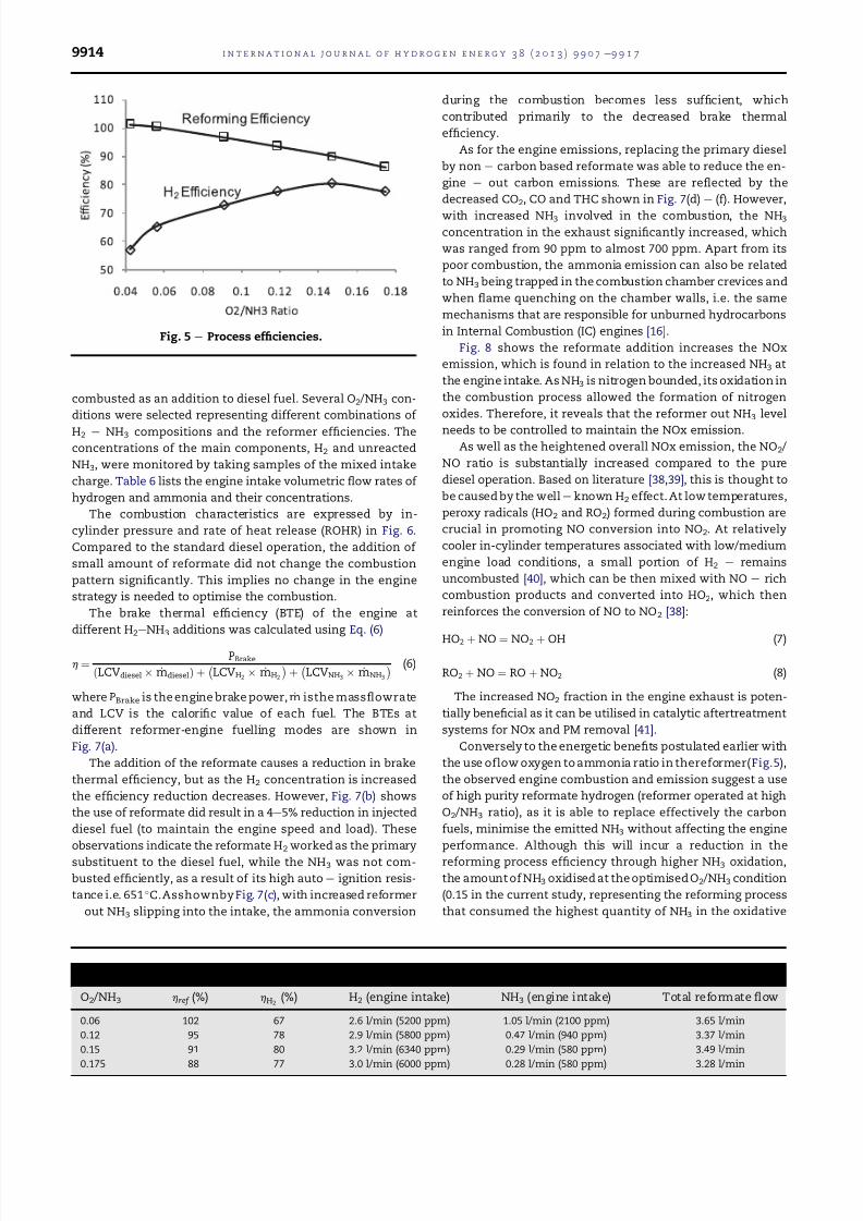
The hydrogen efficiency (Eq. (4)) and reforming process
efficiency (Eq. (5)) of the NH3 exhaust gas reforming are shown
in Fig. 5. Although the hydrogen efficiency was improved at
high O2 /NH3 ratios i.e. higher H2 production, the reforming
processefficiency decreased due to larger NH3 consumption in
exothermic oxidation. Thus a trade e off is shown between
these efficiencies. It is suggested that applying the carbon e
free reformate (as fuel) to an engine under a low O2 /NH3 ratio
(e.g. 0.06) is expected to be more beneficial in terms of diesel
fuel replacement and the engine CO2 emission.
3.3. Application of NH3 exhaust gas reforming in diesel
combustion and emission
In order to study how reformate produced under different
efficiencies could affect engine combustion and emissions,
the reformate was added into the engine’s intake and
Fig. 4 e (a) NH3 conversion in NH3 e ATR at different O2 /NH3 ratios over 8 g and 16 g catalysts; dotted line: 16 g catalyst, solid
line: 8 g catalyst. (b) e (d): H2 production as a function of NH3 concentration and O2 /NH3 ratio; (b) NH3 e ATR over 8 g catalyst,
(c) NH3 eATR over 16 g catalyst and (d) NH3 exhaust gas reforming over 16 g catalyst.
i n t e r n a t i o n a l j o u r n a l o f h y d r o g e n e n e r g y 3 8 ( 2 0 1 3 ) 9 9 0 7 e9 9 1 7 9913
combusted as an addition to diesel fuel. Several O2 /NH3 con-
ditions were selected representing different combinations of
H2 e NH3 compositions and the reformer efficiencies. The
concentrations of the main components, H2 and unreacted
NH3, were monitored by taking samples of the mixed intake
charge. Table 6 lists the engine intake volumetric flow rates of
hydrogen and ammonia and their concentrations.
The combustion characteristics are expressed by in-
cylinder pressure and rate of heat release (ROHR) in Fig. 6.
Compared to the standard diesel operation, the addition of
small amount of reformate did not change the combustion
pattern significantly. This implies no change in the engine
strategy is needed to optimise the combustion.
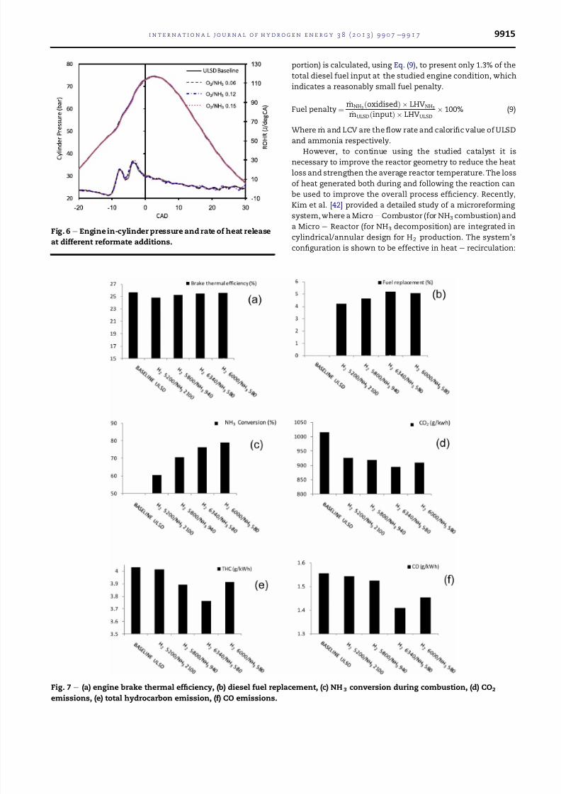
The brake thermal efficiency (BTE) of the engine at
different H2eNH3 additions was calculated using Eq. (6)
h ¼ PBrake
ðLCVdiesel _mdieselÞ þ
LCVH2 _mH2
þ
LCVNH3 _mNH3
(6)
where PBrake is the engine brake power, _m isthe massflowrate
and LCV is the calorific value of each fuel. The BTEs at
different reformer-engine fuelling modes are shown in
Fig. 7(a).
The addition of the reformate causes a reduction in brake
thermal efficiency, but as the H2 concentration is increased
the efficiency reduction decreases. However, Fig. 7(b) shows
the use of reformate did result in a 4e5% reduction in injected
diesel fuel (to maintain the engine speed and load). These
observations indicate the reformate H2 worked as the primary
substituent to the diesel fuel, while the NH3 was not com-
busted efficiently, as a result of its high auto e ignition resis-
tance i.e. 651 C.Asshownby Fig. 7(c), with increased reformer
e out NH3 slipping into the intake, the ammonia conversion
during the combustion becomes less sufficient, which
contributed primarily to the decreased brake thermal
efficiency.
As for the engine emissions, replacing the primary diesel
by non e carbon based reformate was able to reduce the en-
gine e out carbon emissions. These are reflected by the
decreased CO2, CO and THC shown in Fig. 7(d) e (f). However,
with increased NH3 involved in the combustion, the NH3
concentration in the exhaust significantly increased, which
was ranged from 90 ppm to almost 700 ppm. Apart from its
poor combustion, the ammonia emission can also be related
to NH3 being trapped in the combustion chamber crevices and
when flame quenching on the chamber walls, i.e. the same
mechanisms that are responsible for unburned hydrocarbons
in Internal Combustion (IC) engines [16].
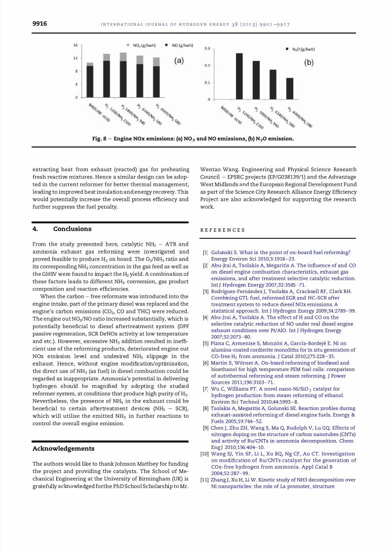
Fig. 8 shows the reformate addition increases the NOx
emission, which is found in relation to the increased NH3 at
the engine intake. As NH3 is nitrogen bounded, its oxidation in
the combustion process allowed the formation of nitrogen
oxides. Therefore, it reveals that the reformer out NH3 level
needs to be controlled to maintain the NOx emission.
As well as the heightened overall NOx emission, the NO2 /
NO ratio is substantially increased compared to the pure
diesel operation. Based on literature [38,39], this is thought to
be caused by the well e known H2 effect. At low temperatures,
peroxy radicals (HO2 and RO2) formed during combustion are
crucial in promoting NO conversion into NO2. At relatively
cooler in-cylinder temperatures associated with low/medium
engine load conditions, a small portion of H2 e remains
uncombusted [40], which can be then mixed with NO e rich
combustion products and converted into HO2, which then
reinforces the conversion of NO to NO2 [38]:
HO2 þ NO ¼ NO2 þ OH (7)
RO2 þ NO ¼ RO þ NO2 (8)
The increased NO2 fraction in the engine exhaust is poten-
tially beneficial as it can be utilised in catalytic aftertreatment
systems for NOx and PM removal [41].
Conversely to the energetic benefits postulated earlier with
the use oflow oxygen to ammonia ratio in thereformer(Fig.5),
the observed engine combustion and emission suggest a use
of high purity reformate hydrogen (reformer operated at high
O2 /NH3 ratio), as it is able to replace effectively the carbon
fuels, minimise the emitted NH3 without affecting the engine
performance. Although this will incur a reduction in the
reforming process efficiency through higher NH3 oxidation,
the amount of NH3 oxidised at the optimised O2 /NH3 condition
(0.15 in the current study, representing the reforming process
that consumed the highest quantity of NH3 in the oxidative
Fig. 5 e Process efficiencies.
Table 6 e Reformate flow rates under different reactor conditions and their compositions in the engine intake.
O2 /NH3 href (%) hH2 (%) H2 (engine intake) NH3 (engine intake) Total reformate flow
0.06 102 67 2.6 l/min (5200 ppm) 1.05 l/min (2100 ppm) 3.65 l/min
0.12 95 78 2.9 l/min (5800 ppm) 0.47 l/min (940 ppm) 3.37 l/min
0.15 91 80 3.2 l/min (6340 ppm) 0.29 l/min (580 ppm) 3.49 l/min
0.175 88 77 3.0 l/min (6000 ppm) 0.28 l/min (580 ppm) 3.28 l/min
i n t e r n a t i o n a l j o u r n a l o f h y d r o g e n e n e r g y 3 8 ( 2 0 1 3 ) 9 9 0 7 e9 9 1 79914
portion) is calculated, using Eq. (9), to present only 1.3% of the
total diesel fuel input at the studied engine condition, which
indicates a reasonably small fuel penalty.
Fuel penalty ¼_mNH3 ðoxidisedÞ LHVNH3
_mULSD ðinputÞ LHVULSD 100% (9)
Where _m and LCV are theflow rate and calorific value of ULSD
and ammonia respectively.
However, to continue using the studied catalyst it is
necessary to improve the reactor geometry to reduce the heat
loss and strengthen the average reactor temperature. The loss
of heat generated both during and following the reaction can
be used to improve the overall process efficiency. Recently,
Kim et al. [42] provided a detailed study of a microreforming
system, where a Micro e Combustor (for NH3 combustion) and
a Micro e Reactor (for NH3 decomposition) are integrated in
cylindrical/annular design for H2 production. The system’s
configuration is shown to be effective in heat e recirculation:
Fig. 6 e Engine in-cylinder pressure and rate of heat release
at different reformate additions.
Fig. 7 e (a) engine brake thermal efficiency, (b) diesel fuel replacement, (c) NH 3 conversion during combustion, (d) CO2
emissions, (e) total hydrocarbon emission, (f) CO emissions.
i n t e r n a t i o n a l j o u r n a l o f h y d r o g e n e n e r g y 3 8 ( 2 0 1 3 ) 9 9 0 7 e9 9 1 7 9915
extracting heat from exhaust (reacted) gas for preheating
fresh reactive mixtures. Hence a similar design can be adop-
ted in the current reformer for better thermal management,
leading to improved heat insulation and energy recovery. This
would potentially increase the overall process efficiency and
further suppress the fuel penalty.
4. Conclusions
From the study presented here, catalytic NH3 e ATR and
ammonia exhaust gas reforming were investigated and
proved feasible to produce H2 on board. The O2 /NH3 ratio and
its corresponding NH3 concentration in the gas feed as well as
the GHSV were found to impact the H2 yield. A combination of
these factors leads to different NH3 conversion, gas product
composition and reaction efficiencies.
When the carbon e free reformate was introduced into the
engine intake, part of the primary diesel was replaced and the
engine’s carbon emissions (CO2, CO and THC) were reduced.
The engine out NO2 /NO ratio increased substantially, which is
potentially beneficial to diesel aftertreatment system (DPF
passive regeneration, SCR DeNOx activity at low temperature
and etc.). However, excessive NH3 addition resulted in ineffi-
cient use of the reforming products, deteriorated engine out
NOx emission level and undesired NH3 slippage in the
exhaust. Hence, without engine modification/optimisation,
the direct use of NH3 (as fuel) in diesel combustion could be
regarded as inappropriate. Ammonia’s potential in delivering
hydrogen should be magnified by adopting the studied
reformer system, at conditions that produce high purity of H2.
Nevertheless, the presence of NH3 in the exhaust could be
beneficial to certain aftertreatment devices (NH3 e SCR),
which will utilise the emitted NH3 in further reactions to
control the overall engine emission.
Acknowledgements
The authors would like to thank Johnson Matthey for funding
the project and providing the catalysts. The School of Me-
chanical Engineering at the University of Birmingham (UK) is
gratefully acknowledged forthe PhD School Scholarship to Mr.
Wentao Wang. Engineering and Physical Science Research
Council e EPSRC projects (EP/G038139/1) and the Advantage
West Midlands and the European Regional Development Fund
as part of the Science City Research Alliance Energy Efficiency
Project are also acknowledged for supporting the research
work.
r e f e r e n c e s
[1] Golunski S. What is the point of on-board fuel reforming?Energy Environ Sci 2010;3:1918e23.
[2] Abu-Jrai A, Tsolakis A, Megaritis A. The influence of and COon diesel engine combustion characteristics, exhaust gasemissions, and after treatment selective catalytic reduction.Int J Hydrogen Energy 2007;32:3565e71.
[3] Rodrıguez-Fernandez J, Tsolakis A, Cracknell RF, Clark RH.Combining GTL fuel, reformed EGR and HC-SCR aftertreatment system to reduce diesel NOx emissions. Astatistical approach. Int J Hydrogen Energy 2009;34:2789e99.
[4] Abu-Jrai A, Tsolakis A. The effect of H and CO on theselective catalytic reduction of NO under real diesel engineexhaust conditions over Pt/AlO. Int J Hydrogen Energy2007;32:2073e80.
[5] Plana C, Armenise S, Monzon A, Garcıa-Bordeje E. Ni onalumina-coated cordierite monoliths for in situ generation of CO-free H2 from ammonia. J Catal 2010;275:228e35.
[6] Martin S, Wo ¨ rner A. On-board reforming of biodiesel andbioethanol for high temperature PEM fuel cells: comparisonof autothermal reforming and steam reforming. J PowerSources 2011;196:3163e71.
[7] Wu C, Williams PT. A novel nano-Ni/SiO 2 catalyst forhydrogen production from steam reforming of ethanol.Environ Sci Technol 2010;44:5993e8.
[8] Tsolakis A, Megaritis A, Golunski SE. Reaction profiles during exhaust-assisted reforming of diesel engine fuels. Energy &Fuels 2005;19:744e52.
[9] Chen J, Zhu ZH, Wang S, Ma Q, Rudolph V, Lu GQ. Effects of nitrogen doping on the structure of carbon nanotubes (CNTs)and activity of Ru/CNTs in ammonia decomposition. ChemEng J 2010;156:404e10.
[10] Wang SJ, Yin SF, Li L, Xu BQ, Ng CF, Au CT. Investigationon modification of Ru/CNTs catalyst for the generation of COx-free hydrogen from ammonia. Appl Catal B2004;52:287e99.
[11] Zhang J, Xu H, Li W. Kinetic study of NH3 decomposition overNi nanoparticles: the role of La promoter, structure
Fig. 8 e Engine NOx emissions: (a) NO2 and NO emissions, (b) N2O emission.
i n t e r n a t i o n a l j o u r n a l o f h y d r o g e n e n e r g y 3 8 ( 2 0 1 3 ) 9 9 0 7 e9 9 1 79916
sensitivity and compensation effect. Appl Catal A2005;296:257e67.
[12] Chellappa AS, Fischer CM, Thomson WJ. Ammoniadecomposition kinetics over NiePt/Al2O3 for PEM fuel cellapplications. Appl Catal A 2002;227:231e40.
[13] Zamfirescu C, Dincer I. Ammonia as a green fuel andhydrogen source for vehicular applications. Fuel ProcessTechnol 2009;90:729e37.
[14] Klerke A, Christensen CH, Norskov JK, Vegge T. Ammonia forhydrogen storage: challenges and opportunities. J MaterChem 2008;18:2304e10.
[15] Kim JH, Kwon OC. A micro reforming system integrated witha heat-recirculating micro-combustor to produce hydrogenfrom ammonia. Int J Hydrogen Energy 2011;36:1974e83.
[16] Reiter AJ, Kong S-C. Combustion and emissionscharacteristics of compression-ignition engine using dualammonia-diesel fuel. Fuel 2011;90:87e97.
[17] Gill SS, Chatha GS, Tsolakis A, Golunski SE, York APE.Assessing the effects of partially decarbonising a dieselengine by co-fuelling with dissociated ammonia. Int JHydrogen Energy 2012;37:6074e83.
[18] Schlapbach L, Zuttel A. Hydrogen-storage materials formobile applications. Nature 2001;114:353e8.
[19] Christensen CH, Johannessen T, Sørensen RZ, Nørskov JK.Towards an ammonia-mediated hydrogen economy? CatalToday 2006;111:140e4.
[20] Zamfirescu C, Dincer I. Using ammonia as a sustainable fuel. J Power Sources 2008;185:459e65.
[21] Zamfirescu C, Dincer I. Utilization of hydrogen producedfrom urea on board to improve performance of vehicles. Int JHydrogen Energy 2011;36:11425e32.
[22] Yin S-F, Zhang Q-H, Xu B-Q, Zhu W-X, Ng C-F, Au C-T.Investigation on the catalysis of COx-free hydrogengeneration from ammonia. J Catal 2004;224:384e96.
[23] Ganley JC, Seebauer EG, Masel RI. Development of amicroreactor for the production of hydrogen from ammonia. J Power Sources 2004;137:53e61.
[24] Yosuke S, Hiroshi M, Tetsuo N, Yuji A, Takashi S. Hydrogengeneration system with ammonia cracking for a fuel-cellelectric vehicle. SAE Tech Paper 2009. 2009-01-1901.
[25] Schriber TJ, Parravano G. The low temperature oxidation of ammonia over a supported ruthenium catalyst. Chem Eng Sci 1967;22:1067e78.
[26] Ng PF, Li L, Wang S, Zhu Z, Lu G, Yan Z. Catalytic ammoniadecomposition over industrial-waste-supported Ru catalysts.Environ Sci Technol 2007;41:3758e62.
[27] Gay SE, Ehsani M. Ammonia hydrogen carrier for fuel cellbased transportation. SAE Technical Paper 2003. 2003-01-2251.
[28] Ishimatsu S, Saika T, Nohara T. Ammonia fueled fuel cellVehicle:The new concept of a hydrogen supply system. SAETechnical Paper 2004. 2004-01-1925.
[29] Chein R-Y, Chen Y-C, Chang C-S, Chung JN. Numericalmodeling of hydrogen production from ammoniadecomposition for fuel cell applications. Int J HydrogenEnergy 2010;35:589e97.
[30] Prasad V, Karim AM, Arya A, Vlachos DG. Assessment of overall rate expressions and multiscale, microkinetic modeluniqueness via experimental data injection: ammoniadecomposition on Ru/g-Al2O3 for hydrogen production. IndEng Chem Res 2009;48:5255e65.
[31] Tsai W, Vajo JJ, Weinberg WH. Inhibition by hydrogen of theheterogeneous decomposition of ammonia on platinum. JPhys Chem 1985;89:4926e32.
[32] Zheng W, Zhang J, Xu H, Li W. Decomposition kinetics onsupported Ru clusters: morphology and particle size effect.Catal Lett 2007;119:311e8.
[33] Bradford MCJ, Fanning PE, Vannice MA. Kinetics of NH3
decomposition over well dispersed Ru. J Catal1997;172:479e84.
[34] Lo ¨ ffler DG, Schmidt LD. Kinetics of NH3 decomposition oniron at high temperatures. J Catal 1976;44:244e58.
[35] Lau CS, Tsolakis A, Wyszynski ML. Biogas upgrade to syn-gas(H2eCO) via dry and oxidative reforming. Int J HydrogenEnergy 2011;36:397e404.
[36] Tsolakis A, Golunski SE. Sensitivity of process efficiency toreaction routes in exhaust-gas reforming of diesel fuel.Chem Eng J 2006;117:131e6.
[37] Ladommatos N, Abdelhalim S, Zhao H. The effects of exhuastgas recirculation on diesel combustion and emissions. Int JEngine 2000;1:107e26.
[38] Varde KS, Frame GA. Hydrogen aspiration in a directinjection type diesel engine-its effects on smoke and otherengine performance parameters. Int J Hydrogen Energy1983;8:549e55.
[39] Lilik GK, Zhang H, Herreros JM, Haworth DC, Boehman AL.Hydrogen assisted diesel combustion. Int J Hydrogen Energy2010;35:4382e98.
[40] Liu S, Li H, Liew C, Gatts T, Wayne S, Shade B, et al. Anexperimental investigation of NO2 emission characteristicsof a heavy-duty H2-diesel dual fuel engine. Int J HydrogenEnergy 2011;36:12015e24.
[41] Gill SS, Chatha GS, Tsolakis A. Analysis of reformed EGR onthe performance of a diesel particulate filter. Int J HydrogenEnergy 2011;36:10089e99.
[42] Kim JH, Um DH, Kwon OC. Hydrogen production fromburning and reforming of ammonia in a microreforming system. Energy Conversion Manage 2012;56:184e91.
i n t e r n a t i o n a l j o u r n a l o f h y d r o g e n e n e r g y 3 8 ( 2 0 1 3 ) 9 9 0 7 e9 9 1 7 9917