Embed Size (px)
Citation preview
AMISTAD DAM AND RESERVOIR
PROJECT
ON THE RIO GRANDE NEAR DEL RIO, TEXAS
CIUDAD ACUNA, COAHUILA
A JOINT PROJECT OF
THE UNITED STATES AND MEXICO
UNDER THE SUPERVISION OF THE INTERNATIONAL BOUNDARY
AND WATER COMMISSION
AMISTAD DAM AND RESERVOIR
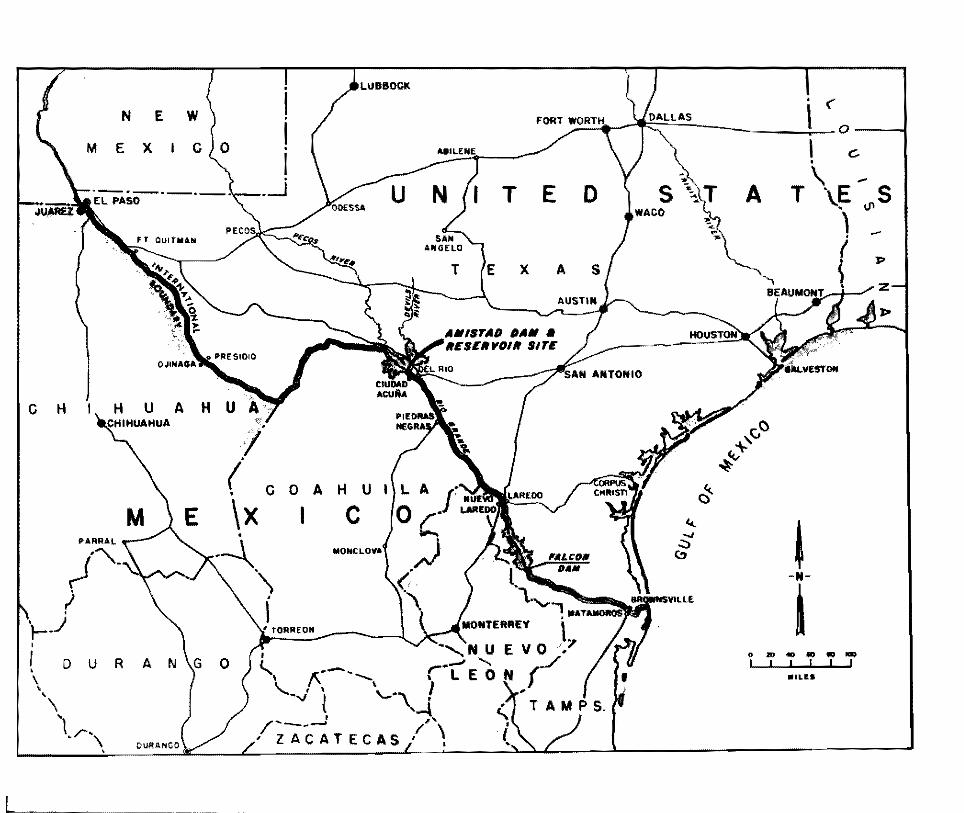
Amistad Dam, located on the Rio Grande, twelve miles upstream from Del Rio, Texas-Ciudad Acuna, Coahuila, is the second major international storage dam to be constructed jointly by the United States and :vlexico, pursuant to the Water Treaty of 1944. The first, Falcon Dam, located about 294 miles downstream from the Amistad site, was completed in 1953.
Agreement with :vlexico for joint construction of Amistad Dam by the Governments of the United States and of Mexico, in accordance >vitb the provisions of the Water Treaty of 1944, was authorized by the Congress of the United States in Public Law 86-605, July 7, 1960.
Construction of Amistad Dam is being performed by the two Governments through their respective Sections of the International Boundary and Water Commission, United States and Mexico.
Amistad Dam, in conjunction with Falcon Dam, will achieve the purpose set forth in the Treaty of providing for the conservation, storage, and regulation of the greatest quantity of the annual flow of the Rio Grande in a way to ensure continuance of
existing uses and the development of the greatest number of feasible projects within the limits imposed by the water allotments specified to each country.
The dam will prevent loss of life and great property damage in both countries such as occurred from the floods in 1954 and 1958. The dam is designed to control, to the safe downstream channel capacity, the maximum flood of record originating above the dam site. Incident to releases of water for domestic and irrigation uses, Amistad Dam will have an energy generation potential of 323,000,000 kilowatt hours annually to be divided equally between the two countries in accordance with the Treaty.
In addition to its primary function of flood control, water conservation, and power generation, the Amistad Reservoir will bring new recreational opportunities to the surrounding area. The reservoir will extend up the Rio Grande approximately 74 miles at conservation level, forming a fresh-water lake well suited to recreation and conveniently located with respect to numerous cities and communities, both in the United Ststes and Mexico, to make it an international recreational area.
l---------------------- ·······- --·
N E
M E X I
C H H U A
' I • \ ' '
M
w
c 0
T E D
T X A
C 0 A H U
\x c
ON
I
<..., 1'\---"--v' l
I
--~
' < 0
I c. •
T \ E -"'s \J,
-l>
c} ~
~ .....,
.;::, (!)
-N-
l 0 .. ... "' .. ... I I I I I I
••u•
a c_,
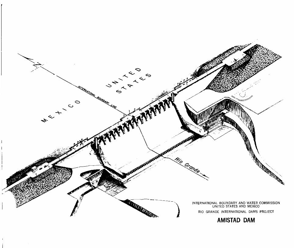
INTERNATIONAL BOUNDARY AND WATER COMMISSION UNITED STATES AND MEXICO
RIO GRANDE INTERNATIONAL DAMS PROJECT
AMISTAD DAM
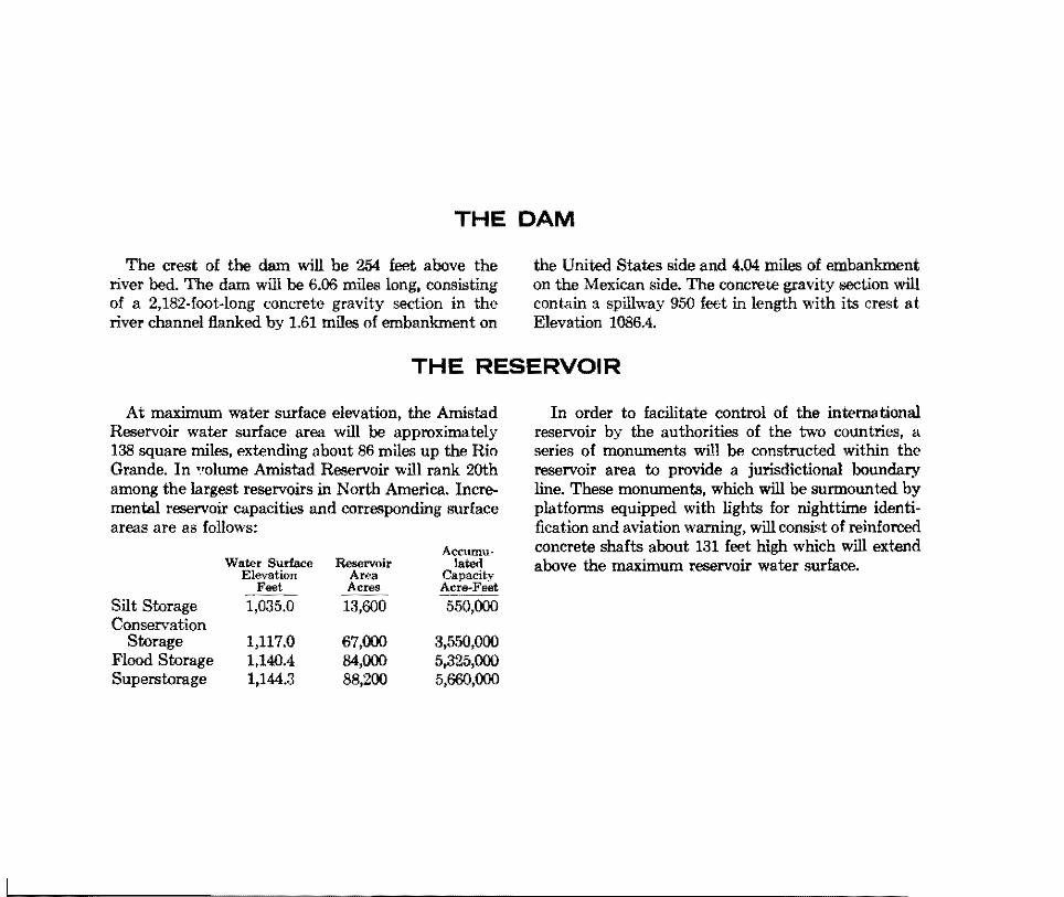
THE DAM
The crest of the dam will be 254 feet above the river bed. The dam will be 6.06 miles long, consisting of a 2,182-foot-long concrete gravity section in the river channel flanked by 1.61 miles of embankment on
the United States side and 4.04 miles of embankment on the Mexican side. The concrete gravity section will contain a spillway 950 foot in length with its crest at Elevation 1086.4.
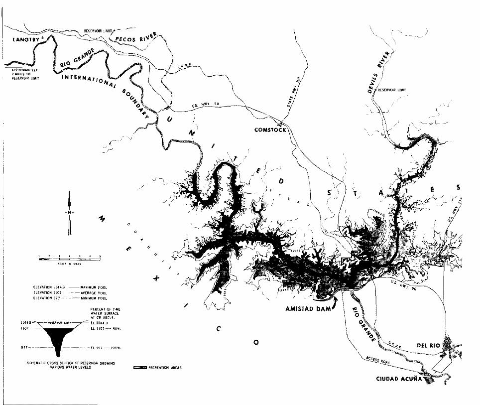
THE RESERVOIR
At maximum water surface elevation, the Amistad Reservoir water surface area will be approximately 138 square miles, extending about 86 miles up the Rio Grande. In •.•olurne Amistad Reservoir will rank 20th among the largest reservoirs in North America. Incremental reservoir capacities and corresponding surface areas are as follows:
Accumu~ Water Surface Reservoir Ia ted
Elevation A""' Capacity Feet Acres Acre-Feet
--····~-
Silt Storage 1,035.0 13,600 550,000 Conservation
Storage 1,117.0 67,000 3,550,000 Flood Storage 1,140.4 84,000 5,325,000 Superstorage 1,144.3 88,200 5,660,000
In order to facilitate control of the international reservoir by the authorities of the two countries, a series of monuments will be constructed within the reservoir area to provide a jurisdictional boundary line. These monuments, which will be surmounted by platforms equipped with lights for nighttime identitication and aviation warning, will consist of reinforced concrete shafts about 131 feet high which will extend above the maximum reservoir water surface.
HEVATION ! ;4 0
(L£YATION 1:07
ELEVAllON 917 -
- MAXINUIJ POOL
__ ~ •VEIIAG£ POOl _ -~ MHIIIIIUM POOL
f>fRC£NT o;_ T~ME WATER S:JR•A<.l fiT OR ABOVf.
EL !!44.3
El II01 ----- 50'1'~
-fl_'lll-100%
ECT!Ofl Of RESERVOtR SHOWING '
CHUlAllC CROSS S WATER LEVElS VARIOUS
/
0
+
~ RECREAT•ON AR£AS
' s ..
/
0
\
'
s r
)
i' J
s
SITE SELECTION
Field surveys and geological investigations were started by the International Boundary and Water Commission in 1948 to locate the most suitable site for Amistad Dam. They extended through the Big Bend section of the Rio Grande from Santa Helena Canyon to below the mouth of the Devils River, a total distance of 320 miles. Some 45 prospective sites were studied, of which 13 were found to be entirely
feasible with respect to geologic and engineering considerations.
The Amistad site, located one mile below the confluence of the Devils River, was finally selected because of its strategic location below the confluences of the Pecos and the Devils Rivers, the sources of the highest floods on the Rio Grande.
PLANS
The site, capacities, and type of dam were recommended by the Commission in Minute dated June 19, 1958, and subsequently approved by the two Governments. Recommendations for construction of Amistad Dam, and the design and procedures, were recommended in Minutes dated January 12, 1961, and September 28, 1963, respectively, and soon thereafter approved by the two Governments.
The detailed plans and specifications for the dam
were jointly performed by the two Governments through the Commission. The design work was divided between the two Sections of the Commission and performed under mutually agreed-upon design criteria. The detailed plans and specifications assigned to the United States Section were performed under its supervision by the U. S. Army Engineer District, Fort Worth, Corps of Engineers. Those assigned to the Mexican Section were performed under its supervision by the Ministry of Hydraulic Resources, Mexico, D. F.
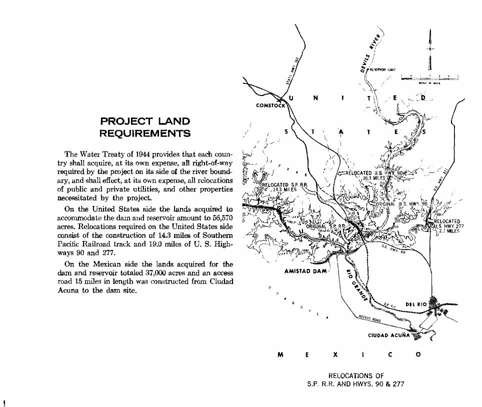
PROJECT LAND REQUIREMENTS
The Water Treaty of 1944 provides that each country shall acquire, at its own expense, all right-of-way required by the project on its side of the river boundary, and shall effect, at its own expense, all relocations of public and private utilities, and other properties necessitated by the project.
On the United States side the lands acquired to acconunodate the dam and reservoir amount to 56,570 acres. Relocations required on the United States side consist of the construction of 14.3 miles of Southern Pacific Railroad track and 19.0 miles of U. S. Highways 90 and 277.
On the Mexican side the lands acquired for the dam and reservoir totaled 37,000 acres and an access road 15 miles in length was constructed from Ciudad Acuna to the dam site.
M E X c 0
RELOCATIONS OF S.P. R.R. AND HWYS. 90 & 277
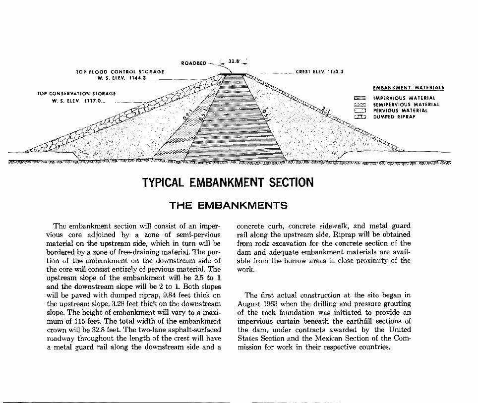
TOP FLOOD CONTROL STORAGE W. S. ELEV. 1144.3 _ -~
TOP CONSERVATION STORAGE
W. S. ELEV. 1117.0.~
CREST ELEV. 1152.3
EMBANKMENT MATERIALS
Eilll!3 IMPERVIOUS MATERIAL 6'""51 SEMIPERVIOUS MATERIAL = PERVIOUS MATERIAL = DUMPED RIPRAP
TYPICAL EMBANKMENT SECTION
THE EMBANKMENTS
The embankment section will consist of an impervious core adjoined by a zone of semi-pervious material on the upstream side, which in turn will be bordered by a zone of free-draining material. The portion of the embankment on the downstream side of tbe core will consist entirely of pervious material. The upstream slope of the embankment will be 2.5 to 1 and the downstream slope will be 2 to 1. Both slopes will be paved with dumped riprap, 9.84 feet thick on the upstream slope, 3.28 feet thick on the downstream slope. The height of embankment will vary to a maximum of 115 feet. The total width of the embankment crown will be 32.8 feet. The two-lane asphalt-surfaced roadway throughout the length of the crest will have a metal guard rail along the downstream side and a
concrete curb, concrete sidewalk, and metal guard rail along the upstream side. Riprap will be obtained from rock excavation for the concrete section of the dam and adequate embankment materials are available from the borrow areas in close proximity of the work.
The first actual construction at the site began in August 1963 when the drilling and pressure grouting of the rock foundation was initiated to provide an impervious curtain beneath the earthfill sections of the dam, under contracts awarded by the United States Section and the Mexican Section of the Commission for work in their respective countries.
li ROADWAY AND AXIS OF DAM 27.0'
fOP Of _DAM H. 1152.3_~"";'1Jf!<:O>i'P'_C0:>1'F .. .T_A_IN_T_ER_(i_A_TE El. 1140.4 ~~ fOP OF DAM EL. 1152.3 ----- ~------
SPILLWAY CREST El.l086.4 ~SPRAY WALL
n FUTURE ; I : I /POWERHOUSE I u __
431'-3.
SECTION THRU SPILLWAY TYPICAL
NON-OVERFLOW SECTION
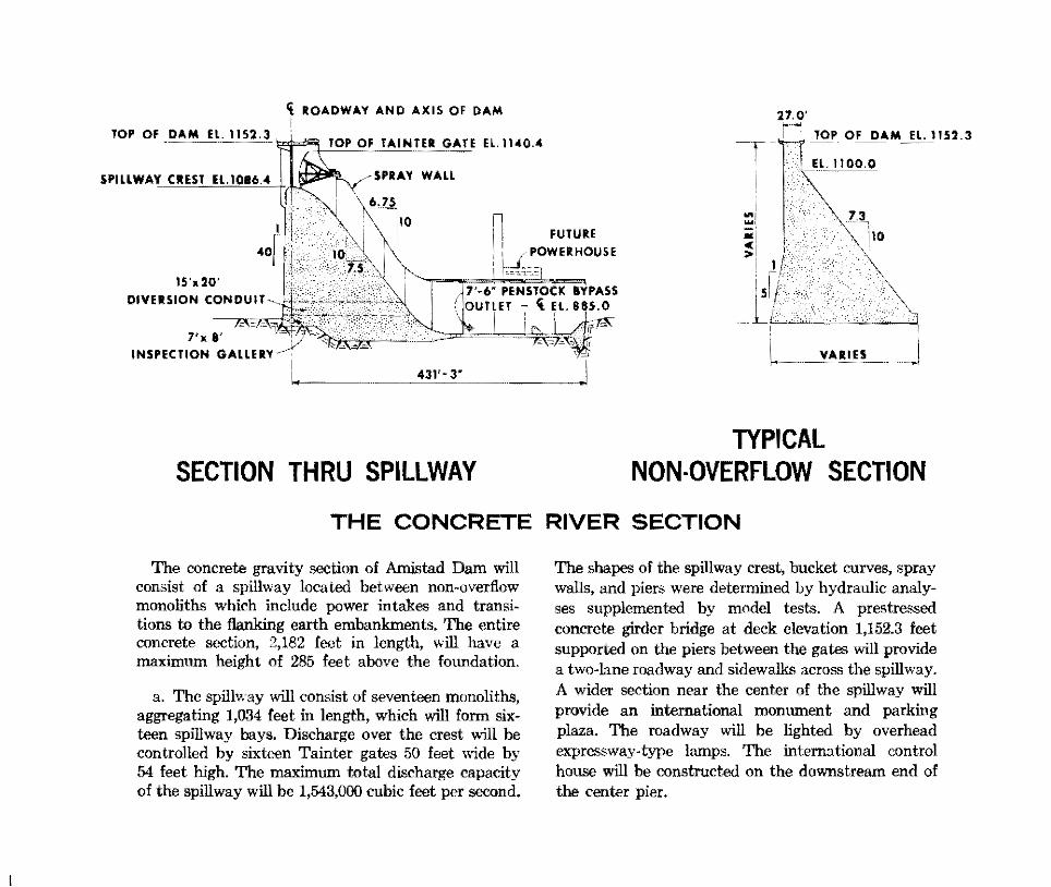
THE CONCRETE RIVER SECTION
The concrete gravity section of Amistad Dam will consist o£ a spillway located between non-overflow monoliths which include power intakes and transitions to the flanking earth embankments. The entire concrete section, 2,182 feet in length, v.ill have a maximum height of 285 feet above the foundation.
a. The spillway will consist of seventeen monoliths, aggregating 1,034 feet in length, which will form sixteen spillway bays. Discharge over the crest will be controlled by sixteen Tainter gates 50 feet wide by 54 feet high. The maximum total discharge capacity of the spillway will be 1,543,000 cubic feet per second.
The shapes of the spillway crest, bucket curves, spray walls, and piers were determined by hydraulic analyses supplemented by model test.~. A prestressed concrete girder bridge at deck elevation 1,152.3 feet supported on the piers between the gates 'viii provide a two-lane roadway and sidewalks across the spillway. A wider section near the center of the spillway will provide an international monument and parking plaza. The roadway will be lighted by overhead expressway-type lamps. The international control house will be constructed on the downstream end of tbe center pier.
GATE MACHINE.Y \ \ ROADWAY AND AXIS OF DAM
SECTION THRU U. S. POWER MONOLITH
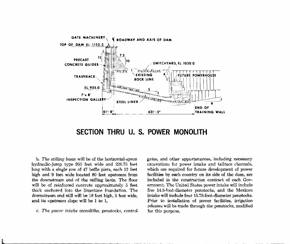
b. The stilling basin will be of the horizontal-apron hydraulic-jump type 950 feet wide and 226.75 feet long with a single row of 47 batHe piers, each 12 feet high and 9 feet wide located 80 feet upstream from the downstream end of the stilling basin. The floor will be of reinforced concrete approximately 5 feet thick anchored into the limestone foundation. The downstream end still will be 18 feet high, 5 feet wide, and its upstream slope will be I to 1.
c. The power intake monoliths, penstocks, control
gates, and other appurtenances, including necessary excavations for power intake and tailrace channels, which are required for future development of power facilities by each country on its side of the dam, are included in the construction contract of each Government. The United States power intake will include five 14.5-foot-diameter penstocks, and the Mexican intake will include four 15.75-foot-diameter penstocks. Prior to installation of power facilities, irrigation releases will be made through the penstocks, modified for this purpose.
SHARING OF COST OF PROJECT
Division of Costs
Pursuant to the 1944 Treaty the cost of the dam is shared by the United States and Mexico in the same proportion as the conservation capacity of the reservoir is divided between the two countries, i.e., 56.2% to United States, 43.8% to Mexico. Each country will install, at its own expense, penstocks and other works required for future installation of its power plant.
The total costs of the dam are estimated to be approximately $78,000,000, including costs of facilities needed in the dam for future power plants.
Each Government will separately install at its expense the powerhouse and hydroelectric generating units it requires in the areas planned for this purpose on each side of the dam, at such times in the future as each determines such installation to be feasible.
Other Project Costs
In addition to the cost of the lands required within its territory to accommodate the project, each country will bear the cost of appurtenant features 'within its territory, such as camps and access roads necessary for construction, and for future operation and maintenance of the project.
CONSTRUCTION
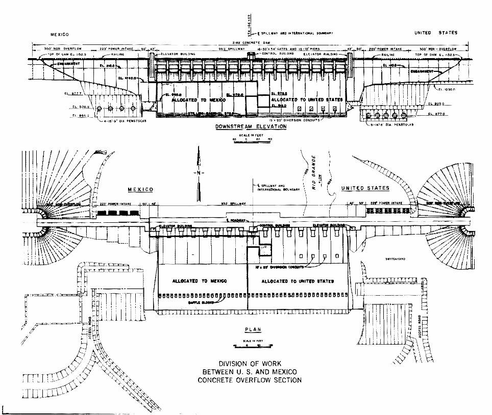
Construction of the dam is being divided between the two countries by allocating to each for performance, items of work the total estimated cost of which corresponds to its respective share of the cost of the dam. Construction work has been so divided that each country will construct certain features of the dam located within its territory consisting of the earth embankment section, the non-overflow monoliths in the concrete channel section, including penstocks and other facilities for future power plant installation. In addition, and in order to effect the proper division of work, the construction of the spillway and stilling basin will be shared by the two countries with the work divided approximately as shown on the following page.
Principal quanti ties of the work allocated to the United States are 6,000,000 cubic yards of earth embankment construction, 1,300,000 cubic yards of rock excavation, the placing of approximately 900,000 cubic yards of concrete, and the furnishing and installing of 10,000,000 pounds of structural steel, including the sixteen Tainter gates.
Principal quantities of the Mexican work are 7,500,000 cubic yards of earth embankment construction, 1,800,000 cubic yards of rock excavation, the placing of about 765,000 cubic yards of concrete, and the furnishing and installation of 3,000,000 pounds of structural steel.
MEXICO
: / --~ ' ' / -, . /
MEXICO
~I • ~~l SPI~lWiiit liiUllllltHI"'t.ToOIIIiL BOUII!)Joll'(
i
DOWNSTREAM ELEVATION
SCiiLE ~~ ru;r t006Qltll
It'• lit OI'IIMIOII
ALLOCATED TO UNITfn STATU
666868668~668888886886
PLAN
f(..OI.t ,,. •en «i£:S'f
DIVISION OF WORK BETWEEN U. S. AND MEXICO
CONCRETE OVERFLOW SECTION
UNITEO STATES
I
SCHEDULE OF CONSTRUCTION
Construction of the dam began in January 1965 and is scheduled for completion in March 1969. The various stages of construction have been so scheduled that the dam will have been raised to a sufficient height to permit impoundment of waters by the spring of 1968 prior to beginning of the flood season of that year. Construction by each Government is being performed by contract, with each advertising and letting its contract for work assigned to its country in accordance with its laws and regulations. The contractor for work assigned to the United States is a joint venture of four United States' firms, namely: Perini Corporation, Framington, Massachusetts, C. H.
Leavell & Co., El Paso, Texas, J. A. Jones Construction Co., Charlotte, North Carolina, and Vinnell Corporation, Alhambra, California. The contractor for the work assigned to Mexico is the firm, La Victoria y Asociados, S.A., Mexico, D. F.
The project is under the over-all supervision of the International Boundary and Water Commission, United States and Mexico. The United States contract is administered by United States Connnissioner Joseph F. Friedkin, and the Mexican contract by Mexican Connnissioner David Herrera Jordan.