Embed Size (px)
Citation preview

AmiAntit Polyolefin Piping Systems Co.Product Guide HDPE Pipe Systems


1 General 2
2 Introduction 2
3 Production Process 3
4 Product Advantages 4
5 Product Characteristics 5 5.1 Molecular structure 5 5.2 Raw material classifications 5 5.3 Raw material colour 6 5.4 Pipe material classification 6 5.5 Material regression curve 6
6 Product Technical Data 7 6.1 Pipe wall thickness/weight/tolerances etc. 7 6.2 Steel backing rings dimensions 8 6.3 Allowable bending radius 9 6.4 Support Distance of HDPE Pipes (PE 100) 9 6.5 Excellent flow characteristics 10 6.6 Overall Service (Design) Coefficient (C) or Safety Factory 11 6.7 UV Resistance 11 6.8 Abrasion Resistance 11 6.9 Thermal Expansion & Contraction 11 6.10 Reduction Factor 11 6.11 Chemical Resistance Data 11
7 Product Range 13 7.1 Pipes 14 7.2 Fitting and accessories 15
7.2.1 Electrofusion Fittings and Adaptors 157.2.2 Injection-moulded Fittings 177.2.3 Segment-Welded Fittings 187.2.4 Compression Fittings Pe100 Sdr11 Pn16 19
8 Quality Control 21 8.1 QC test method with reference standards 22 8.2 Certificates and approvals 23
9 Underground Installations 24 9.1 Trenching & bed preparation 24 9.2 Trench construction & dimensions 24 9.3 Backfilling 24
10 Pipe Joining 24 10.1 Butt-fusion welding process 27 10.2 Electrofusion welding process 27 10.3 Compression coupling joint 28 10.4 Flange connection joint 28
11 Handling, Unloading and Storage 29 11.1 Straight lengths and bundles 29 11.2 Coils 29
12 Location Plan 31
1
10
11
12
09
08
07
06
05
04
03
02
01

01
02
03
04
05
06
07
08
09
10
11
2
AmIAntIt Group of Companies
The AmiAnTiT Group is a leading global industrial organization which manufactures high-quality pipe systems and researches, develops, owns and licenses advanced pipe technologies; it also provides water management services. The Group supports global infrastructure development projects and delivers to municipal, industrial, agricultural and energy markets worldwide.
AmiAnTiT has a presence in more than 70 countries, including almost 30 wholly-owned or joint-ventured manufacturing facilities in the middle East, Europe, Latin America, north Africa, The Far East, Central Asia, the indian Subcontinent and Africa. AmiAnTiT manufacturing capabilities are supported by technology companies and sales offices across the globe.
Other members of the Group are predominantly limited liability companies, owned by the AmiAnTiT Group in varying percentages, which operate under individual commercial registrations.
AmIAntIt Polyolefin Piping Systems Co.
APPSCo AmiAnTiT Polyolefin Piping Systems Company (APPSCo) is a member of the AmiAnTiT Group of companies and started full commercial production in 2002. The company manufactures high density polyethylene (HDPE) solid wall pipe for pressure applications (with diameters ranging from 16 mm to 630 mm). in addition to this, APPSCo has the in-house capabilities to produce all types of related fittings, in order to provide its customers with complete piping systems and solutions. APPSCo, constructed on a 100,000 m2 site in Al-Khumra, South Jeddah, Saudi Arabia, uses the most advanced and up-to-date extrusion technology to ensure consistent high-quality products - with an annual capacity over 16,000 tons - while the plant is able to increase its capacity in accordance with market demand and requirements.
2 Introduction The world’s infrastructure is ageing. millions of kilometres of gas, water and sewer pipe need rehabilitation. The predicament is a worldwide problem in industrial countries, although this is not the case in many developing countries, where an ageing infrastructure is not a problem. A water infrastructure does not exist and it remains to be constructed. But these nations are facing other, difficult decisions about how to build and what materials to use in order to avoid what has happened in the more developed countries.
The main problem encountered in ageing structures is corrosion. And corrosion is not a reversible process. internally unprotected sewer pipes are rapidly deteriorating due to the presence of sulphuric acid in sanitation (sewerage) systems, which is generated through the hydrogen sulphide cycle. Externally, soil conditions and stray electrical currents deteriorate underground pipes. metallic pipes corrode when placed in poorly-drained soils with low resistivity. The presence of sulphate-reducing bacteria accelerates this corrosion. These problems can be significantly reduced, if not eliminated, by careful selection of pipe materials, which should have corrosion-resistance protection. The remedy to this situation is very simple: AmiAnTiT Polyolefin APPSCo pipes.
1 General

APPSCo is equipped with a modern continuous extrusion process polyethylene pipe-manufacturing facility. APPSCo is capable of producing both High Density Polyethylene (HDPE) and medium Density Polyethylene pipes in accordance with iSO 4427, Din 8074 for water applications and iSO 4473, ASTm D2513 for gas applications - and any other standard required by the customers. The production process starts with the raw material, which can be either virgin HDPE and is in the form of granules. These are set to dry in the dryer in order to evaporate any water or moisture that has condensed on the raw material granules. This is then transported to the main hopper system, which doses the measured, weighed raw material into the extruder. The extruder heats the raw material to a temperature of between 180 and 200˚C (356-392˚ F) which is the idle temperature
for extrusion and shaping of HDPE. This is then ejected from the extruder in a continuous pipe shape to the screen changer. The screen changer examines the extruded product for impurities and removes them accordingly. Once the product has been extruded and cleansed of any impurities, the die and mandrel section takes place. In this section both the diameters and standard pipe dimensions are set, the die shapes the pipe diameter and the mandrels set the standard pipe dimensions (SPD). When the product has taken its final shape, it moves to the cooling & vacuum tanks. in the cooling tank the pipes are calibrated and cooled down for the final stage. The final stage consists of marking, cutting or possibly coiling the pipes.
01
02
03
04
05
06
07
08
09
10
11
3
Colling SectionUpto 180 mm
Raw Material Conveying SystemSilo Dryer
AdditivesFeeder
Tooling (Mandrel and Die)
CalibratorUltrasonicMeasurement
Haul OffCuttingDumping Tray
Pipe Marking
MainCompoundFeeder
Screen Changer
ExtruderCooling Parts Cooling Tank
3 Production Process

4
01
02
03
04
05
06
07
08
09
10
11
Feature Benefits
High flexibility combined with high impact
resistance
Can be supplied as coils of up to 160 mm (external pipediameter). Coils reduce the number of joints and stress to thesite. Under the same conditions, PE pipe develops much lowersurge pressures than rigid pipes. Unaffected by soil settlement. High tenacity and anti-impact intensity. Excellent resistance against inappropriate handling with low notch sensitivity and high tear resistance
Squeeze-off ability With no damage to or effect on the pipe’s short & long termproperties
UV resistance With no damage to or effect on the pipe’s short & long termproperties
High chemical and corrosion resistance Does not rust or corrode scaling and corrosion by electrolytic actions. Lower life cycle cost, long life expectancy. Very lowmaintenance. Withstands aggressive soil conditions, groundwater. Suitable for use with a broad range of chemicals.Resistance to all natural gas constituents.
Non-toxic material Approved for use in drinking water applications. Approved forfood contact.
Abrasion resistance HDPE pipes outperform conventional pipes, depending on theapplication, by a factor of 7
Low thermal conductivity Thermal conductivity value of 0.4 W/m.°C
Excellent flow characteristics Polyolefin pipes have a hydraulically smooth bore. In theColebrook formula K is equal to 0.001; in the Hazen-Williamsformula C is equal to 155.
4.1 HDPE Pipes ApplicationsPolyolefin piping systems are used in many applications such as:
• Hot&coldwatersystem• Drinkingpotablewatersupply• Irrigation• Stormwaterdrainage• Landdrainage• Drainageofleachatesystems• Industrialwater• Chemicalprocesspiping• Firefightingsystem
• Domesticgas&oilpipesystems• Wastedisposal• Sewernetwork• Sewer&effluenttreatmentplants• Outfalls• Wastedamps• Industrialwaste• Sand&slurrypumping• Cableducts(non-pressurepipes)
4 Product Advantages

5.1 molecular Structure
Polyethylene (PE) is a polymer consisting of long chains of the monomer ethylene C2H4, also known as ethane. The molecules, which consist of two CH2 groups, are connected by a double bond.
The properties of polyethylene are primarily determined by density, molecular weight and molecular weight distribution. The material properties vary in accordance with density. When density increases, the followingproperties also increase:
Yield stress (tensile strength), Modulus of elasticity, Hardness, Solvent resistance, Impermeability to gases and vapours.
5.2 Raw material ClassificationsPolyethylene is classified into several different categories, based mostly on its density and branching. The mechanical properties of PE depend significantly on variables such as the extent and type of branching, the crystal structure and the molecular weight. Below is a clarification of only the two classifications of PE that APPSCo uses for producing its pipes
HDPE (High density polyethylene)
HDPE is characterized by a density of greater than or equal to 0.941 g/cm3.it has a low degree of branching and thus stronger intermolecular forces and tensile strength. The lack of branching is ensured by an appropriate choice of catalyst and reaction conditions. HDPE is also used in packaging products.
5
01
02
03
04
05
06
07
08
09
10
11
Figure 5-3 Chemical chart of HDPE
The HDPE (High density poly-ethylene) pipe grade material that APPSCo uses has a low degree of branching, with short side chains (“linear polyethylene”). The short side chain allows higher crystallisation, thus resulting in higher density and better material properties.
Figure 5-1 HDPE chain molecules
Figure 5-2 Single HDPE molecule
5 Product Characteristics

6
01
02
03
04
05
06
07
08
09
10
11
5.5 material Regression CurveThe material regression curve shows the material strength in relation to the time at various temperatures (20 ˚C, 60 ˚C and 80 ˚C).
Following the SEm-evaluation according to iSO/TR 9080 for the HDPE material, the regression curves of both PE 100 and PE 80 material is as shown in the following figures:
5.3 Raw material Colour
HDPE basic materials are classified as a non-coloured material. Pre-compounded, coloured HDPE or materials from the supplier are recommended for the manufacturing of pipes; HDPE is available in black, & blue. Other colour can be provided based on request.
PE 80 80 8
PE 100 100 10
Classification ofHDPE
MRSMPa
Classificationnumber
Figure 5-6 Material regression curve for PE 80
Figure 5-7 Material regression curve for PE 100
Figure 5-4 Non-coloured HDPE granules
Figure 5-5 Coloured HDPE granules
Pipe colour is dictated by the applications for which they are to be used. Black and blue coloured pipes are for potable water applications and yellow are for gas applications. Other pipe colours are possible depending on the relevant water/district authority requirements.
5.4 Pipe material Classification
High density polyethylene (HDPE) pipe grade material is classified as PE 100 and PE 80. The classification number for a thermoplastic material is 10 times the minimum required strength of the material (mRS) as shown in the following table
Table 5-1 Classification of HDPE material
Note:The points below need to be considered / submitted by the pipe manufacturer in order to confirm the right material to be used:
Raw material technical data sheet.
Proof of the material having been listed as PE 100 or PE 80, by third parties (e.g. the Plastic pipe institute – Listing in technical report TR # 4, or RAL listing for HDPE material).
Third party long term test report to show mRS value and the raw material regression curve as per iSO/TR 9080.
in the case of potable water, the material supplier and material code need to be approved by organizations to in order to confirm their compliance with AnSi # 61 (nSF and WRAS).
UV stabilizers, colour, antioxidants and pigments are included in the pre-compounded material.

01
02
03
04
05
06
07
08
09
10
11
7
16
0.
3 2.
3 0.
4 0.
10
2.0
0.3
0.09
-
-
-
- -
- -
- -
- -
- -
- -
- -
- -
16.3
1.
2
20
0.
3 3.
0 0.
4 0.
16
2.3
0.4
0.13
2.
3 0.
3 0.
12
-
- -
- -
- -
- -
- -
- -
- -
- -
20.3
1.
2
25
0.
3 3.
5 0.
5 0.
24
3.0
0.4
0.21
2.
3 0.
4 0.
17
2.0
0.3
0.15
-
- -
- -
- -
- -
- -
- -
- -
25.3
1.
2
32
0.
3 4.
4 0.
6 0.
39
3.6
0.5
0.33
3.
0 0.
4 0.
28
2.4
0.4
0.23
2.
0 0.
3 0.
19
- -
- -
- -
- -
- -
- -
32.3
1.
3
40
0.
4 5.
5 0.
7 0.
60
4.5
0.6
0.51
3.
7 0.
5 0.
43
3.0
0.5
0.36
2.
4 0.
4 0.
29
2.0
0.3
0.25
-
- -
- -
-
- -
40.4
1.
4
50
0.
4 6.
9 0.
8 0.
94
5.6
0.7
0.79
4.
6 0.
6 0.
67
3.7
0.5
0.55
3.
0 0.
4 0.
45
2.4
0.4
0.37
2.
0 0.
3 0.
31
- -
- -
- -
50.4
1.
4
63
0.
4 8.
6 1.
0 1.
48
7.1
0.9
1.26
5.
8 0.
7 1.
05
4.7
0.6
0.87
3.
8 0.
5 0.
72
3.0
0.4
0.58
2.
5 0.
4 0.
49
- -
- -
- -
63.4
1.
5
75
0.
5 10
.3
1.2
2.10
8.
4 1.
0 1.
77
6.8
0.8
1.47
5.
6 0.
7 1.
24
4.5
0.6
1.01
3.
6 0.
5 0.
82
2.9
0.4
0.67
-
- -
- -
- 75
.5
1.6
90
0.
6 12
.3
1.4
3.02
10
.1
1.2
2.56
8.
2 1.
0 2.
13
6.7
0.8
1.77
5.
4 0.
7 1.
46
4.3
0.6
1.18
3.
5 0.
5 0.
97
- -
- -
- -
90.6
1.
8
11
0 0.
7 15
.1
1.7
4.52
12
.3
1.4
3.80
10
.2
1.1
3.16
8.
1 1.
0 2.
63
6.6
0.8
2.17
5.
3 0.
7 1.
78
4.2
0.6
1.43
-
-
- -
- 11
0.7
2.2
12
5 0.
8 17
.1
1.9
5.81
14
.0
1.6
4.91
11
.4
1.3
4.16
9.
2 1.
1 3.
38
7.4
0.9
2.77
6.
0 0.
7 2.
27
4.8
0.6
1.84
-
- -
- -
- 12
5.8
2.5
14
0 0.
9 19
.2
2.1
7.30
15
.7
1.7
6.15
12
.7
1.4
5.11
10
.3
1.2
4.24
8.
3 1.
0 3.
48
6.7
0.8
2.84
5.
4 0.
7 2.
32
- -
- -
- -
140.
9 2.
8
16
0 1.
0 21
.9
2.3
9.51
17
.9
1.9
8.01
14
.6
1.6
6.70
11
.8
1.3
5.53
9.
5 1.
1 4.
54
7.7
0.9
3.73
6.
2 0.
8 3.
05
- -
- -
-
161.
0 3.
2
18
0 1.
1 24
.6
2.6
12.0
2 20
.1
2.2
10.1
4 16
.4
1.8
8.47
13
.3
1.5
7.02
10
.7
1.2
5.74
8.
6 1.
0 4.
68
6.9
0.8
3.79
-
- -
- -
- 18
1.1
3.6
20
0 1.
2 27
.4
2.9
14.8
7 22
.4
2.4
12.5
3 18
.2
2.0
10.4
5 14
.7
1.6
8.61
11
.9
1.3
7.08
9.
6 1.
1 5.
80
7.7
0.9
4.71
-
- -
- -
- 20
1.2
4.0
22
5 1.
4 30
.8
3.2
18.7
9 25
.2
2.7
15.8
7 20
.5
2.2
13.2
3 16
.6
1.8
10.9
3 13
.4
1.5
8.98
10
.8
1.2
7.33
8.
6 1.
0 5.
91
- -
- -
- -
226.
4 4.
5
25
0 1.
5 34
.2
3.6
23.2
0 27
.9
2.9
19.5
22
.7
2.4
16.2
7 18
.4
2.0
13.4
7 14
.8
1.6
11.0
1 11
.9
1.3
8.97
9.
6 1.
1 7.
33
- -
- -
- -
251.
5 5.
0
28
0 1.
7 38
.3
4.0
29.0
9 31
.3
3.3
24.5
1 25
.4
2.7
20.4
0 20
.6
2.2
16.8
7 16
.6
1.8
13.8
3 13
.4
1.5
11.3
2 10
.7
1.2
9.14
-
- -
- -
- 28
1.7
9.8
31
5 1.
9 43
.1
4.5
36.8
2 35
.2
3.7
31.0
1 28
.6
3.0
25.8
2 23
.2
2.5
21.3
9 18
.7
2.0
17.5
1 15
.0
1.6
14.2
3 12
.1
1.4
11.6
4 9.
7 1.
1 9.
40
7.7
0.9
7.53
31
6.9
11.1
35
5 2.
2 48
.5
5.0
46.6
9 39
.7
4.1
39.3
8 32
.2
3.4
32.7
7 26
.1
2.8
27.1
2 21
.1
2.3
22.2
9 16
.9
1.8
18.0
7 13
.6
1.5
14.7
2 10
.9
1.2
11.8
9 8.
7 1.
0 9.
58
357.
2 12
.5
40
0 2.
4 54
.7
5.6
59.3
0 44
.7
4.6
49.9
5 36
.3
3.8
41.6
1 29
.4
3.1
34.3
8 23
.7
2.5
28.1
7 19
.1
2.1
23.0
4 15
.3
1.7
18.6
6 12
.3
1.4
15.1
4 9.
8 1.
1 12
.14
402.
4 14
.0
45
0 2.
7 -
- -
50.3
5.
2 63
.25
40.9
4.
2 52
.69
33.1
3.
5 43
.55
26.7
2.
8 35
.69
21.5
2.
3 29
.14
17.2
1.
9 23
.59
13.8
1.
5 19
.07
11.0
1.
2 15
.31
452.
7 15
.6
50
0 3.
0 -
- -
55.8
5.
7 77
.94
45.4
4.
7 65
.01
36.8
3.
8 53
.74
29.7
3.
1 44
.09
23.9
2.
5 35
.95
19.1
2.
1 29
.10
15.3
1.
7 23
.52
12.3
1.
4 19
.06
503.
0 17
.5
56
0 3.
4 -
- -
- -
- 50
.8
5.2
81.4
5 41
.2
4.3
67.4
3 33
.2
3.5
55.2
4 26
.7
2.8
44.9
9 21
.4
2.3
36.4
8 17
.2
1.9
29.6
0 13
.7
1.5
23.7
3 56
3.4
19.6
63
0 3.
8 -
- -
- -
- 57
.2
5.9
103.
19
46.3
4.
8 85
.22
37.4
3.
9 69
.96
30.0
3.
1 56
.83
24.1
2.
6 46
.22
19.3
2.
1 37
.34
15.4
1.
7 30
.02
633.
8 22
.1
Pro
duc
t te
chni
cal d
ata
PE
100
Sta
ndar
d d
imen
sion
rat
io (
SD
R)
7.
4 9
11
13.6
17
21
26
33
41
Nom
inal
pre
ssur
e (P
N)
bar
P
E 1
00
PN
25
PN
20
PN
16
PN
12.
5 P
N 1
0 P
N 8
P
N 6
P
N 5
P
N 4
Pi
pe O
D Min
imum W
.T W.
T tolera
nce L
inear w
eight
Minimu
m W.T
W.T tole
rance
Linear w
eight
Minimu
m W.T
W.T tole
rance
Linear w
eight
Minimu
m W.T
W.T tole
rance
Linear w
eight
Minimu
m W.T
W.T tole
rance [3
] Linea
r weight
[4] Min
imum W
.T W.T
toleran
ce Linea
r weight
Minimu
m W.T
W.T tole
rance
Linear w
eight
Minimu
m W.T
W.T tole
rance
Linear w
eight
Minimu
m W.T
W.T tole
rance
Linear w
eight[4]
(mm)
(m
m)
(mm)
(kg
/m)
(mm)
(m
m)
(kg/m
) (m
m)
(mm)
(kg
/m)
(mm)
(m
m)
(kg/m
) (m
m)
(mm)
(kg
/m)
(mm)
(m
m)
(kg/m
) (m
m)
(mm)
(kg
/m)
(mm)
(m
m)
(kg/m
) (m
m)
[3](m
m)
(kg/m
)
[1]
Ova
lity
tole
ranc
es c
alcu
late
d a
s p
er IS
O 1
1922
-1 G
rad
e N
[2]
OD
tole
ranc
es c
alcu
late
d a
s p
er IS
O 1
1922
-1 g
rad
e B
(0.
006
DN
, rou
nded
up
to th
e ne
xt g
reat
er 0
.1 m
m w
ith m
inim
um v
alue
of 0
.3 m
m a
nd m
ax 4
.0 m
m.
[3
] Th
ickn
ess
tole
ranc
es c
alcu
late
d a
s p
er IS
O 1
1922
-1 g
rad
e V
(0.
1WTm
in +
0.1)
mm
roun
ded
up
to th
e ne
xt 0
.1 m
m.
[4
] Th
e w
eig
ht c
alcu
late
d w
ith a
vera
ge
den
sity
of 0
.955
g/c
m.
Outsi
dedia
meter
OD{2}
Ovali
ty[1]
6 P
rod
uct
Tech
nica
l Dat
a

01
02
03
04
05
06
07
08
09
10
11
8
16
0.
3 2.
3 0.
4 0.
10
2.0
0.3
0.09
-
-
-
- -
- -
- -
- -
- -
- -
- -
- -
16.3
1.
2
20
0.
3 3.
0 0.
4 0.
16
2.3
0.4
0.13
2.
0 0.
3 0.
12
-
- -
- -
- -
- -
- -
- -
- -
- -
20.3
1.
2
25
0.
3 3.
5 0.
5 0.
24
3.0
0.4
0.21
2.
3 0.
4 0.
17
2.0
0.3
0.15
-
- -
- -
- -
- -
- -
- -
- -
25.3
1.
2
32
0.
3 4.
4 0.
6 0.
39
3.6
0.5
0.33
3.
0 0.
4 0.
28
2.4
0.4
0.23
2.
0 0.
3 0.
19
- -
- -
- -
- -
- -
- -
32.3
1.
3
40
0.
4 5.
5 0.
7 0.
60
4.5
0.6
0.51
3.
7 0.
5 0.
43
3.0
0.5
0.36
2.
4 0.
4 0.
29
2.0
0.3
0.25
-
- -
- -
-
- -
40.4
1.
4
50
0.
4 6.
9 0.
8 0.
94
5.6
0.7
0.79
4.
6 0.
6 0.
67
3.7
0.5
0.55
3.
0 0.
4 0.
45
2.4
0.4
0.37
2.
0 0.
3 0.
31
- -
- -
- -
50.4
1.
4
63
0.
4 8.
6 1.
0 1.
48
7.1
0.9
1.26
5.
8 0.
7 1.
05
4.7
0.6
0.87
3.
8 0.
5 0.
72
3.0
0.4
0.58
2.
5 0.
4 0.
49
- -
- -
- -
63.4
1.
5
75
0.
5 10
.3
1.2
2.10
8.
4 1.
0 1.
77
6.8
0.8
1.47
5.
6 0.
7 1.
24
4.5
0.6
1.01
3.
6 0.
5 0.
82
2.9
0.4
0.67
-
- -
- -
- 75
.5
1.6
90
0.
6 12
.3
1.4
3.02
10
.1
1.2
2.56
8.
2 1.
0 2.
13
6.7
0.8
1.77
5.
4 0.
7 1.
46
4.3
0.6
1.18
3.
5 0.
5 0.
97
- -
- -
- -
90.6
1.
8
11
0 0.
7 15
.1
1.7
4.52
12
.3
1.4
3.80
10
.0
1.1
3.16
8.
1 1.
0 2.
63
6.6
0.8
2.17
5.
3 0.
7 1.
78
4.2
0.6
1.43
-
-
- -
- 11
0.7
2.2
12
5 0.
8 17
.1
1.9
5.81
14
.0
1.6
4.91
11
.4
1.3
4.10
9.
2 1.
1 3.
38
7.4
0.9
2.77
6.
0 0.
7 2.
27
4.8
0.6
1.84
-
- -
- -
- 12
5.8
2.5
14
0 0.
9 19
.2
2.1
7.30
15
.7
1.7
6.15
12
.7
1.4
5.11
10
.3
1.2
4.24
8.
3 1.
0 3.
48
6.7
0.8
2.84
5.
4 0.
7 2.
32
- -
- -
- -
140.
9 2.
8
16
0 1.
0 21
.9
2.3
9.51
17
.9
1.9
8.01
14
.6
1.6
6.70
11
.8
1.3
5.53
9.
5 1.
1 4.
54
7.7
0.9
3.73
6.
2 0.
8 3.
05
- -
- -
-
161.
0 3.
2
18
0 1.
1 24
.6
2.6
12.0
2 20
.1
2.2
10.1
4 16
.4
1.8
8.47
13
.3
1.5
7.02
10
.7
1.2
5.74
8.
6 1.
0 4.
68
6.9
0.8
3.79
-
- -
- -
- 18
1.1
3.6
20
0 1.
2 27
.4
2.9
14.8
7 22
.4
2.4
12.5
3 18
.2
2.0
10.4
5 14
.7
1.6
8.61
11
.9
1.3
7.08
9.
6 1.
1 5.
80
7.7
0.9
4.71
-
- -
- -
- 20
1.2
4.0
22
5 1.
4 30
.8
3.2
18.7
9 25
.2
2.7
15.8
7 20
.5
2.2
13.2
3 16
.6
1.8
10.9
3 13
.4
1.5
8.98
10
.8
1.2
7.33
8.
6 1.
0 5.
91
- -
- -
- -
226.
4 4.
5
25
0 1.
5 34
.2
3.6
23.2
0 27
.9
2.9
19.5
0 22
.7
2.4
16.2
7 18
.4
2.0
13.4
7 14
.8
1.6
11.0
1 11
.9
1.3
8.97
9.
6 1.
1 7.
33
- -
- -
- -
251.
5 5.
0
28
0 1.
7 38
.3
4.0
29.0
9 31
.3
3.3
24.5
1 25
.4
2.7
20.4
0 20
.6
2.2
16.8
7 16
.6
1.8
13.8
3 13
.4
1.5
11.3
2 10
.7
1.2
9.14
-
- -
- -
- 28
1.7
9.8
31
5 1.
9 43
.1
4.5
36.8
2 35
.2
3.7
31.0
1 28
.6
3.0
25.8
2 23
.2
2.5
21.3
9 18
.7
2.0
17.5
1 15
.0
1.6
14.2
3 12
.1
1.4
11.6
4 9.
7 1.
1 9.
40
7.7
0.9
7.53
31
6.9
11.1
35
5 2.
2 48
.5
5.0
46.6
9 39
.7
4.1
39.3
8 32
.2
3.4
32.7
7 26
.1
2.8
27.1
2 21
.1
2.3
22.2
9 16
.9
1.8
18.0
7 13
.6
1.5
14.7
2 10
.9
1.2
11.8
9 8.
7 1.
0 9.
58
357.
2 12
.5
40
0 2.
4 54
.7
5.6
59.3
0 44
.7
4.6
49.9
5 36
.3
3.8
41.6
1 29
.4
3.1
34.3
8 23
.7
2.5
28.1
7 19
.1
2.1
23.0
4 15
.3
1.7
18.6
6 12
.3
1.4
15.1
4 9.
8 1.
1 12
.14
402.
4 14
.0
45
0 2.
7 -
- -
50.3
5.
2 63
.25
40.9
4.
2 52
.69
33.1
3.
5 43
.55
26.7
2.
8 35
.69
21.5
2.
3 29
.14
17.2
1.
9 23
.59
13.8
1.
5 19
.07
11.0
1.
2 15
.31
452.
7 15
.6
50
0 3.
0 -
- -
55.8
5.
7 77
.94
45.4
4.
7 65
.01
36.8
3.
8 53
.74
29.7
3.
1 44
.09
23.9
2.
5 35
.95
19.1
2.
1 29
.10
15.3
1.
7 23
.52
12.3
1.
4 19
.06
503.
0 17
.5
56
0 3.
4 -
- -
- -
- 50
.8
5.2
81.4
5 41
.2
4.3
67.4
3 33
.2
3.5
55.2
4 26
.7
2.8
44.9
9 21
.4
2.3
36.4
8 17
.2
1.9
29.6
0 13
.7
1.5
23.7
3 56
3.4
19.6
63
0 3.
8 -
- -
- -
- 57
.2
5.9
103.
19
46.3
4.
8 85
.22
37.4
3.
9 69
.96
30.0
3.
1 56
.83
24.1
2.
6 46
.22
19.3
2.
1 37
.34
15.4
1.
7 30
.02
633.
8 22
.1
Pro
duc
t te
chni
cal d
ata
PE
80
Sta
ndar
d d
imen
sion
rat
io (
SD
R)
7.
4 9
11
13.6
17
21
26
33
41
Nom
inal
pre
ssur
e (P
N)
bar
P
E 8
0 P
N 2
0 P
N 1
6 P
N 1
2.5
PN
10
PN
8
PN
6
PN
5
PN
4
PN
3.2
Pi
pe O
D Min
imum W
.T W.
T tolera
nce L
inear w
eight
Minimu
m W.T
W.T tole
rance
Linear w
eight
Minimu
m W.T
W.T tole
rance
Linear w
eight
Minimu
m W.T
W.T tole
rance
Linear w
eight
Minimu
m W.T
W.T tole
rance [3
] Linea
r weight
[4] Min
imum W
.T W.T
toleran
ce Linea
r weight
Minimu
m W.T
W.T tole
rance
Linear w
eight
Minimu
m W.T
W.T tole
rance
Linear w
eight
Minimu
m W.T
W.T tole
rance
Linear w
eight[4]
(mm)
(m
m)
(mm)
(kg
/m)
(mm)
(m
m)
(kg/m
) (m
m)
(mm)
(kg
/m)
(mm)
(m
m)
(kg/m
) (m
m)
(mm)
(kg
/m)
(mm)
(m
m)
(kg/m
) (m
m)
(mm)
(kg
/m)
(mm)
(m
m)
(kg/m
) (m
m)
[3](m
m)
(kg/m
)
[1]
Ova
lity
tole
ranc
es c
alcu
late
d a
s p
er IS
O 1
1922
-1 G
rad
e N
[2]
OD
tole
ranc
es c
alcu
late
d a
s p
er IS
O 1
1922
-1 g
rad
e B
(0.
006
DN
, rou
nded
up
to th
e ne
xt g
reat
er 0
.1 m
m w
ith m
inim
um v
alue
of 0
.3 m
m a
nd m
ax 4
.0 m
m.
[3
] Th
ickn
ess
tole
ranc
es c
alcu
late
d a
s p
er IS
O 1
1922
-1 g
rad
e V
(0.
1WTm
in +
0.1)
mm
roun
ded
up
to th
e ne
xt 0
.1 m
m.
[4
] Th
e w
eig
ht c
alcu
late
d w
ith a
vera
ge
den
sity
of 0
.955
g/c
m.
Outsi
dedia
meter
OD{2}
Ovali
ty[1]
Tabl
e 6-
1 P
ipe
wal
l thi
ckne
ss/w
eigh
t/to
lera
nces

PCD
ID D
T
PIP
E O
D
Back
ing rin
g P
ress
ure
OD of
bac
king
ID
PC
D
Bol
t hol
e N
o. o
f B
olt s
ize
Torq
ue
Thic
knes
s Ex
tern
al d
ia.
ID
PC
D
B
olt h
ole
No.
of
Bol
t siz
e To
rque
Ga
lvanis
ed st
eel
(m
m)
size
(m
m)
PN
(B
ar)
rin
g (
mm
)
(mm
) (m
m)
dia
. (m
m)
b
olts
valu
e (m
m)
(mm
) (m
m)
(mm
)
dia
. (m
m)
b
olts
(in
ches
) va
lue
(thic
knes
s)
(N.m
m)
(N
.mm
) m
m
20
15
16
95
28
65
14
4
M12
15
12
90
32
60
.5
16.0
4
1/2
15
11
.1
25
20
16
10
5 34
75
14
4
M12
15
14
98
37
70
.0
16.0
4
1/2
15
12
.7
32
25
16
11
5 42
85
14
4
M16
15
16
10
8 44
79
.5
16.0
4
1/2
15
14
.3
40
32
16
14
0 51
10
0 18
4
M16
25
18
11
7 52
89
.0
16.0
4
1/2
25
17
.5
50
40
16
15
0 62
11
0 18
4
M16
35
18
12
7 62
98
.5
16.0
4
1/2
35
17
.5
63
50
16
16
5 78
12
5 18
4
M16
35
18
15
2 78
12
0.5
20.0
4
5/8
35
19
.0
75
65
16
18
5 92
14
5 18
8
M16
40
18
17
8 92
13
9.5
20.0
4
5/8
40
22
.3
90
80
16
20
0 10
8 16
0 18
8
M16
40
20
19
1 10
8 15
2.0
20.0
4
5/8
40
23
.9
11
0 10
0 16
22
0 12
8 18
0 18
8
M16
40
20
22
9 12
8 19
0.5
20.0
8
5/8
40
23
.9
12
5 10
0 16
22
0 13
5 18
0 18
8
M16
45
20
25
4 14
0 21
6.0
23.0
8
3/4
40
23
.9
14
0 12
5 16
25
0 15
8 21
0 18
8
M16
50
24
25
4 15
8 21
6.0
23.0
8
3/4
50
23
.9
16
0 15
0 16
28
5 17
8 24
0 22
8
M20
60
24
27
9 17
8 24
1.0
23.0
8
3/4
60
25
.4
18
0 15
0 16
28
5 18
8 24
0 22
8
M20
60
24
27
9 19
5 24
1.0
23.0
8
3/4
60
25
.4
20
0 20
0 16
34
0 23
5 29
5 22
12
M
20
70
24
343
235
298.
5 23
.0
8 3
/4
70
28.4
22
5 20
0 16
34
0 23
8 29
5 22
12
M
20
70
24
343
240
298.
5 23
.0
8 3
/4
70
28.4
25
0 25
0 16
40
5 28
8 35
5 26
12
M
24
100
30
406
290
362.
0 26
.0
12
7/8
10
0 30
.2
28
0 25
0 16
40
5 29
4 35
5 26
12
M
24
100
30
406
300
362.
0 26
.0
12
7/8
10
0 30
.2
31
5 30
0 16
46
0 33
8 41
0 26
12
M
24
110
34
483
345
432.
0 26
.0
12
7/8
11
0 31
.8
35
5 35
0 16
52
0 37
6 47
0 26
16
M
24
160
42
535
376
476.
0 29
.0
12
1
16
0 35
.0
40
0 40
0 16
58
0 43
0 52
5 30
16
M
27
170
46
600
430
540.
0 29
.0
16
1
17
0 36
.6
45
0 50
0 16
71
5 51
7 65
0 33
20
M
30
190
45
635
480
578.
0 32
.0
16
1.1/
8 19
0 39
.6
50
0 50
0 16
71
5 53
5 65
0 33
20
M
30
190
45
700
533
635.
0 32
.0
20
1.1/
8 19
0 43
.0
56
0 60
0 16
84
0 61
8 77
0 36
20
M
33
220
50
750
590
692.
0 34
.9
20
1.1/
4 22
0 46
.0
63
0 60
0 16
84
0 64
5 77
0 36
20
M
33
220
50
815
660
750.
0 35
.0
20
1.1/
4 22
0 47
.8
(A
S P
ER
AN
SI
CLA
SS
150
B16
.5)
(AS
PE
R D
IN S
TAN
DA
RD
)E
N-1
092-
1 D
IN-2
577,
PN
10/1
6
HD
PE
pip
es s
teel
bac
king
rin
gs
for
stub
flan
ges
Tabl
e 6-
2 S
teel
bac
king
rin
gs d
imen
sion
s
01
02
03
04
05
06
07
08
09
10
11
9

01
02
03
04
05
06
07
08
09
10
11
10
6.3 Allowable Bending Radius
APPSCo polyethylene products are smoother than steel, cast iron, ductile iron, or concrete etc, a smaller PE pipe can carry an equivalent volumetric flow rate at the same pressure. it has less drag and a lower tendency for turbulence at high flow. Because of its superior chemical resistance, APPSCo PE pipes are flexible in behavior, and can be readily bent in the field. in general terms, a minimum bending radius of (20-28 x Dn) outside diameter of the pipe be adopted for PE 100 and PE 80 material.
6.4 Support Distance of HDPE Pipes (PE100)
20 0.4 0.5 0.5 0.5 0.6
25 0.5 0.6 0.6 0.7 0.7
32 0.6 0.8 0.8 0.9 0.9
40 0.8 1.0 1.0 1.1 1.1
50 1.0 1.3 1.3 1.4 1.4
63 1.3 1.6 1.6 1.7 1.8
75 1.5 1.9 1.9 2.0 2.1
90 1.8 2.3 2.3 2.4 2.5
110 2.2 2.8 2.8 3.0 3.1
125 2.5 3.1 3.1 3.4 3.5
140 2.8 3.5 3.5 3.8 3.9
160 3.2 4.0 4.0 4.3 4.5
180 3.6 4.5 4.5 4.9 5.0
200 4.0 5.0 5.0 5.4 5.6
225 4.5 5.6 5.6 6.1 6.3
250 5.0 6.3 6.3 6.8 7.0
280 5.6 7.0 7.0 7.6 7.8
315 6.3 7.9 7.9 8.5 8.8
355 7.1 8.9 8.9 9.6 9.9
400 8.0 10.0 10.0 10.8 11.2
450 9.0 11.3 11.3 12.2 12.6
500 10.0 12.5 12.5 13.5 14.0
560 11.2 14.0 14.0 15.1 15.7 630 12.6 15.8 15.8 17.0 17.6
OD (mm) SDR 9 SDR 11 SDR 13.6 SDR 17 SDR 21
20 0.5 0.5 0.6 0.6 0.6 0.7
25 0.5 0.6 0.7 0.7 0.7 0.8
32 0.6 0.7 0.8 0.8 0.9 0.9
40 0.7 0.9 0.9 1.0 1.0 1.1
50 0.9 1.0 1.0 1.1 1.2 1.2
63 1.0 1.2 1.2 1.3 1.4 1.4
75 1.1 1.3 1.4 1.5 1.5 1.6
90 1.3 1.5 1.6 1.7 1.7 1.8
110 1.5 1.7 1.8 1.9 2.0 2.1
125 1.6 1.8 2.0 2.1 2.2 2.3
140 1.7 2.0 2.1 2.2 2.4 2.5
160 1.9 2.2 2.3 2.5 2.6 2.7
200 2.2 2.5 2.7 2.9 3.0 3.2
225 2.4 2.7 2.9 3.1 3.3 3.4
250 2.6 3.0 3.1 3.3 3.5 3.7
280 2.8 3.2 3.4 3.6 3.8 4.0
315 3.0 3.4 3.7 3.9 4.1 4.3
355 3.3 3.7 4.0 4.2 4.4 4.7
400 3.5 4.0 4.3 4.5 4.8 5.0
450 3.8 4.4 4.7 4.9 5.2 5.5
500 4.1 4.7 5.0 5.3 5.6 5.9
560 4.4 5.1 5.4 5.7 6.0 6.0 630 4.8 5.5 5.8 6.2 6.5 6.8
SIZE SDR 26 SDR 21 SDR 17 SDR 13.6 SDR 11 SDR9
Note: 1. All distance are quoted in meters.2. These distances should not be used for gravity
pipelines.
Minimum allowable bending radius at 24˚C. (in meters)

6.5 Excellent Flow Characteristics
Because polyethylene is smoother than steel, cast iron, ductile iron, or concrete, a smaller PE pipe can carry an equivalent volumetric flow rate at the same pressure. it has less drag and a lower tendency for turbulence at high flow. its superior chemical resistance and “non-stick” surface combine to almost eliminate scaling and pitting and preserve the excellent hydraulic characteristics throughout the pipe service life.
6.6 Overall Service (Design) Coefficient (C) or Safety Factor
“C” is the overall coefficient with a value greater than 1, which takes into consideration service conditions as well as properties of the components of a piping system other than those represented in the lower confidence limit. Safety factors shall be specified in the appropriate product standards. According to iSO 12162 standard, the minimum safety factor for polyethylene pipes is 1.25 for water application and 2 for gas application as per iSO 4437.
6.7 UV Resistance
HDPE material has generally excellent prolonged weather-ability properties and can readily withstand wide variations of weather without degradation. The finely divided carbon black particles dispersed in the HDPE material (2 to 2.5% by weight) will surely ban the effect of the ultraviolet (UV) waves existing in the sunlight. Hence, unlike other plastic materials, HDPE pipes can be stored for years without any fear of degrading and require no additional protection for external storage, or prolonged use in natural conditions.
6.8 Abrasion Resistance
HDPE Pipes have high resistance to abrasion. When conveying solids or slurries that contain coarse- particle-size solids with velocities up to 3 m/s, the expected lifetime of HDPE pipe is much longer than that of other materials like steel, cement and PVC. in general terms HDPE Pipes have superior abrasion resistance to other traditional material and provide a more cost effective solution for abrasive slurry installation.
6.9 thermal Expansion & Contraction
As a result of temperature changes, all materials experience the thermal expansion/ contraction phenomena. Coefficient of linear expansion of polyethylene is higher than most other piping materials. (1.8 x 10⁻⁴ mm/mm.°C). Forces generated by thermal stresses are much lower due to lower modulus of elasticity of polyethylene and its capability to stress relaxes.
6.10 Reduction Factor
Two major factors (working pressure vs. temperature) plays major role in the life span and performance of HDPE Pipes. HDPE can give optimum performance under 20˚ C Temperature. However, if an environment where temperature and working pressure both are high, the following reduction factor in the life’s span of HDPE Pipe will apply:
6.11 Chemical Resistance Data
Unlike other piping materials, polyethylene is highly resistant to a wide range of chemical solutions such as acids, bases and solvents (refer to the following table for more details). Polyethylene pipe will not degrade due to chemicals in the soil. it does not support the microbiological growth as bacteria, fungi and algae. The resistance to a certain chemical depends on three factors: temperature, and chemical concentration.
Two major factors (working pressure vs. temperature) plays major role in the life span and performance of HDPE Pipes. HDPE can give optimum performance under 40˚ Tempera-ture. However, if an environment where temperature and working pressure both are high, the following reduction factor in the life’s span of HDPE Pipe will apply:
01
02
03
04
05
06
07
08
09
10
11
11
Reduction Factor Vs. Temperature
20 30 40
˚C
50 60
Red
uctio
n F
acto
r 10.80.60.40.2
0

01
02
03
04
05
06
07
08
09
10
11
12
Acrylic emulsions S S
Aluminum Chloride S S
Aluminum Chloride con S S
Aluminum Fluoride con S S
Aluminum Sulfate con S S
Ammonia 100% dry gas S S
Ammonium Carbonate S S
Ammonium Chloride sat S S
Ammonium Fluoride 20% S S
Ammonium Metaphosphate sat S S
Ammonium Persulfate sat S S
Ammonium Sulfate sat S S
Ammonium Sulfide sat S S
Ammonium Thiocyanate sat S S
Aniline 100% S NA
Antimony Chloride S S
Barium Carbonate sat S S
Barium Chloride S S
Barium Sulfate sat S S
Barium Sulfide sat S S
Benzene Sulfonic Acid S S
Bismuth Carbonate sat S S
Black Liquor S S
Borax Cold sat S S
Boric Acid d S S
Boric Acid 10% S S
Bromine Liquid 100% O U
Butanediol 10% S S
Butanediol 60% S S
Butanediol 100% S S
Butyl Acetate 100% O U
Calcium Bisulfide S S
Calcium Carbonate sat S S
Calcium Chlorate sat S S
Calcium Hypochlorite Bleach S S
Calcium Nitrate 50% S S
Calcium Sulfate S S
Carbon Dioxide 100% dry S S
Carbon Dioxide 100% wet S S
Carbon Dioxide 100% cold sat S S
Carbon Disulphide NA U
Carbon Monoxide S S
Chlorine liquid O U
Chlorosulfonic Acid U U
Chromic Acid 50% S O
Cider S S
Coconut of alcohols S S
Copper Chloride sat S S
Copper Cyanide sat S S
Copper Fluoride S S
Copper Nitrate sat S S
Copper Sulfate d S S
Copper Sulfate sat S S
Cuprous Chloride sat S S
Cyclohexanone U U
Dextrin sat S S
Dextrose sat S S
Disodium Phosphate S S
Diethylene Glycol S S
Emulsions Photographic S S
Ethyl Chloride O U
Ferric Chloride sat S S
Ferric Nitrate sat S S
Ferrous Chloride sat S S
Ferrous Sulfate S S
Fluoboric Acid S S
Fluorine S U
Fluosilicic Acid 325 S S
Fluosilicic Acid conc S S
Formic Acid 20% S S
Formic Acid 50% S S
Formic Acid 100% S S
Fructose sat S S
Fuel oil S U
Glycol S S
Glycolic acid 30% S S
Hydrobromic acid 30% S S
Hydrocyanic acid sat S S
Hydrochloric Acid 30% S S
Hydrofluoric Acid 40% S S
Hydrofluoric Acid 60% S S
Hydrogen 100% S S
Hydrogen Bromide 10% S S
Hydrogen Chloride Gas dry S S
Hydroquinone S S
Hydrogen Sulfide S S
Hypochlorous Acid conc S S
Lead Acetate sat S S
Magnesium carbonate sat S S
Magnesium Chloride sat S S
Magnesium Hydroxide sat S S
Magnesium Sulfate sat S S
Chemical Chemical60˚C 60˚C20˚C 20˚C

Table Continues…
Legend:
S: SatisfactoryO: Some AttackU: UnsatisfactorynA: no Data Available
d: DilutedConc.: Concentratedsat: Saturatedsol: Solution
ChemicalChemical 60˚C60˚C 20˚C20˚C
Mercuric Chloride S S
Mercuric Cyanide sat S S
Mercurous Nitrate sat S S
Methyl Ethyl Ketone 100% U U
Methyl Bromide O U
Methylsulfuric Acid S S
Methylene Chloride 100% U U
Nickel Chloride sat S S
Nickel Citrate Conc S S
Nickel Sulfate sat S S
Nicotinic Acid S S
Nitric Acid <50% S S
Nitrobenzene 100% U U
Oleum conc U U
Oxalic Acid d S S
Oxalic Acid sat S S
Petroleum Ether U U
Phosphoric Acid 0-30% S S
Phosphoric Acid 90% S S
Photographic Solutions S S
Potassium Bicarbonate sat S S
Potassium Borate 1% S S
Potassium Bromate 10% S S
Potassium Bromide sat S S
Potassium Carbonate S S
Potassium Chlorate sat S S
Potassium Chloride sat S S
Potassium Chromate 40% S S
Potassium Cyanide sat S S
Potassium Ferri/Ferro Cyanide S S
Potassium Fluoride S S
Potassium Nitrate sat S S
Potassium Perborate sat S S
Potassium Perchlorate 10% S S
Potassium Permangante 20 % S S
Propargyl Alcohol S S
Propylene Glycol S S
Propargyl Alcohol S S
Potassium Sulfate conc S S
Potassium Sulfide conc S S
Potassium Sulfite conc S S
Potassium Persulfate sat S S
Sea Water S S
Shortening S S
Silicic Acid S S
Sodium Acetate sat S S
Sodium Benzoate 35% S S
Sodium Bisulfate sat S S
Sodium Bisulfite sat S S
Sodium Borate S S
Sodium Bromide Oil sol S S
Sodium Carbonate conc S S
Sodium Carbonate S S
Sodium Chlorate sat S S
Sodium Chloride sat S S
Sodium Cyanide S S
Sodium Dichromate sat S S
Sodium Ferricyanide sat S S
Sodium Ferro cyanide S S
Sodium Fluoride sat S S
Sodium Nitrate S S
Sodium Sulfate S S
Sodium Sulfide 20% to sat S S
Sodium Sulfite sat S S
Stannous Chloride sat S S
Stannic Chloride sat S S
Starch Solution sat S S
Sulfuric Acid <50% S S
Sulfuric Acid 96% O U
Sulfuric Acid 98% conc O U
Sulfurous Acid S S
Tannic Acid 10% S S
Tetralin U U
Tetrahydrofuran O O
Tichloroacetic Acid S S
Trisodium Phorphate sat S S
Urea S S
Urine S S
Wetting Agents S S
Xylene U U
Zinc Chloride sat S S
Zinc Sulfate sat S S
01
02
03
04
05
06
07
08
09
10
11
13

14
110 269 538
125 275 550
140 281 562
160 289 578
180 297 594
200 305 610
225 315 630
250 325 650
280 337 673
315 351 701
355 642 1283
400 660 1319
450 680 1359
500 700 1399
560 723 1447
630 751 1503
OD Z Laying length(mm) (mm) (mm)
DIA
L
Z
Z
22.5
°, 3
0°
01
02
03
04
05
06
07
08
09
10
11
7.1 Pipes
APPSCo has four production lines and can supply an extensive range of pipes, as well as an outstanding range of fittings and accessories. The product range includes:
PE solid wall pipe from gravity up to 16 bar as a standard rating and up to 32 bar on specific standard requirements.
Pipes with an outside diameter between 16 mm and 630 mm.
12-meter standard pipe length
Diameters of up to 160 mm can be supplied on coils.
7 Product Range
7.2 Fitting and Accessories
Fittings are available as injection-moulded, electrofusion, segment-welded or compression mechanical coupling parts and include:
Tees/ reduced tees wyes (45˚,60˚)
Bends/ elbows.
Reducers.
Flanges connections.
Saddles / tapping tees/ valves.
Cross X
7.2.1 Segment Welded Fittings
22.5° , 30° elbow

15
45° Elbow
60° Elbow
110 269 72 610
125 275 81 631
140 281 90 652
160 289 102 680
180 297 114 708
200 305 127 737
225 315 142 772
250 325 157 807
280 337 175 848
315 351 197 898
355 642 221 1504
400 660 248 1567
450 680 279 1638
500 700 309 1708
560 723 346 1793
630 751 388 1891
OD Z M Laying length(mm) (mm) (mm) (mm)
Z
Z
DIA
45°
60°
DIA
Z
Z
110 269 93 631
125 275 105 655
140 281 117 679
160 289 133 711
180 297 149 743
200 305 165 775
225 315 185 815
250 325 205 855
280 337 228 901
315 351 256 957
355 642 288 1571
400 660 324 1643
450 680 364 1723
500 700 404 1803
560 723 452 1899
630 751 508 2011
OD Z M Laying length(mm) (mm) (mm) (mm)
M
M
01
02
03
04
05
06
07
08
09
10
11
90° Elbow
110 340 680
125 350 700
140 350 700
160 360 720
180 370 740
200 380 760
225 400 800
250 400 800
280 420 840
315 440 880
355 730 1460
400 750 1500
450 780 1560
500 800 1600
560 830 1660
630 870 1740
OD Z L(mm) (mm) (mm)
110 269 93 362
125 275 105 380
140 281 117 398
160 289 133 422
180 297 149 446
200 305 165 470
225 315 185 500
250 325 205 530
280 337 228 565
315 351 256 607
355 642 288 930
400 660 324 984
450 680 364 1044
500 700 404 1104
560 723 452 1175
630 751 508 1259
OD Z M Laying length(mm) (mm) (mm) (mm)
OD
OD
L
Z90°
Z
DIA
Z
90
°
M
M
Equal Tee

16
01
02
03
04
05
06
07
08
09
10
11
45° Wye
110 340 680
125 350 700
140 350 700
160 360 720
180 370 740
200 380 760
225 400 800
250 400 800
280 420 840
315 440 880
355 730 1460
400 750 1500
450 780 1560
500 800 1600
560 830 1660
630 870 1740
OD Z L(mm) (mm) (mm)
90°
OD
OD
Z
L
110 577 282 859
125 588 286 874
140 599 290 889
160 613 296 909
180 627 302 929
200 642 307 949
225 660 315 974
250 678 322 1000
280 700 330 1030
315 725 340 1065
355 1252 652 1904
400 1284 665 1949
450 1320 679 1999
500 1356 693 2050
560 1400 711 2110
630 1450 731 2181
110 458 282 739
125 467 286 753
140 476 290 766
160 487 296 783
180 499 302 801
200 511 307 818
225 525 315 840
250 540 322 862
280 558 330 888
315 578 340 918
355 1016 652 1668
400 1043 665 1707
450 1072 679 1751
500 1101 693 1795
560 1137 711 1847
630 1178 731 1908
OD Z2 Z1 Laying length(mm) (mm) (mm) (mm)
OD Z2 Z1 Laying length(mm) (mm) (mm) (mm)
110 577 282 859
125 588 286 874
140 599 290 889
160 613 296 909
180 627 302 929
200 642 307 949
225 660 315 974
250 678 322 1000
280 700 330 1030
315 725 340 1065
355 1252 652 1904
400 1284 665 1949
450 1320 679 1999
500 1356 693 2050
560 1400 711 2110
630 1450 731 2181
Z2
L
OD
45°
Z1
Z2
L2
OD
60°
Z1
Cross (X) 60° Wye

17
7.2.2 Electro Fusion Fittings and Adapters
EF Coupling EF End Cap
Pressure rating:SDR11 PN16 & SDR17 PN10
Pressure rating:SDR11 PN16 & SDR17 PN10
EF End 90° Elbow EF End 45° Elbow
Pressure rating:SDR11 PN16 & SDR17 PN10
Pressure rating:SDR11 PN16 & SDR17 PN10
EF Concentric Reducer EF Equal Tee
Pressure rating:SDR11 PN16 & SDR17 PN10
Pressure rating:SDR11 PN16 & SDR17 PN10
Pressure rating:SDR11 PN16 & SDR17 PN10
Pressure rating:SDR11 PN16 &SDR17 PN10
EF Service Tee Set Flat EF Repair Adapter
EF Service Tee Set valued
Pressure rating:SDR11 PN16 & SDR17 PN10
Pressure rating:SDR11 PN16 & SDR17 PN10
EF Service Tee Setflat with clamps
01
02
03
04
05
06
07
08
09
10
11

18
01
02
03
04
05
06
07
08
09
10
11
7.2.3 Injection Moulded Fittings
90° Elbow 60° Elbow
Pressure rating:SDR11 PN16 & SDR17 PN10
Pressure rating:SDR11 PN16 &SDR17 PN10
45° Elbow End Cap
Pressure rating:SDR11 PN16 &SDR17 PN10
Pressure rating:SDR11 PN16 &SDR17 PN10
Pressure rating:SDR11 PN16 & SDR17 PN10
Pressure rating:SDR11 PN16 &SDR17 PN10
Equal Tee Reducer Tee
Reducer Flange Adapter
Pressure rating:SDR11 PN16 &SDR 17 PN10
Pressure rating:SDR 11 PN16 &SDR17 PN10
Pressure rating:SDR11 PN16 & SDR17 PN10
Pressure rating:SDR11 PN16 &SDR17 PN10
Steel Flange (Backing Ring) Bland Steel Flange
Pressure rating:SDR11 PN16 &SDR17 PN10
Pressure rating:SDR11 PN16 &SDR17 PN10
Welded Steel Transition Adapter
Transition Adapter Female
Pressure rating:SDR11 PN16 &SDR17 PN10
Transition Adapter Male

19
7.2.4 Compression Fittings PE100 SDR11 PN16
CouplingOD20 mm up toOD110 mm
Reducing CouplingOD20 x 25 mm up to OD110 x 90 mm
Male AdaptorD20 mm x 1/2” up to OD110 mm x 4”
Female AdaptorOD20 mm x 1/2” up toOD 110 mm x 4”
Equal TeeOD20 mm up to OD110 mm
Elbow 90° AND 45°OD20 x 25 mm up toOD110 x 90 mm
Tee With Threaded Female Take OffOD20 mm x 1⁄2” up to OD110 mm x 4”
Tee With Threaded Female Take OffOD20 mm x1/2”x20 mm up to OD110 mm x4”x110 mm
Flange Adaptor(Stub Flange)OD20 mm up toOD630 mm
End CapOD20 mm up to OD315 mm
Reducing TeeOD20 x 16 x 20 mmup to OD110 x 90 x 110 mm
Repair Slip CouplingOD40 mm up toOD110 mm
Female Tee With Peg FittingOD32 mm x 3⁄4” x 32 mm
90° Elbow With Lateral Threaded Female Take OffOD25 mm x 25 mm x 1⁄2”
90° Tee With Increased Take OffOD20 x 25 x 20 mm up to OD40 x 50 x 40 mm
Universal TransitionCouplingOD15 x 25 mm up toOD34 x 32 mm
01
02
03
04
05
06
07
08
09
10
11

20
01
02
03
04
05
06
07
08
09
10
11
Male Adaptor With Brass Threaded InsertOD20 mm x 1⁄2” up toOD63 mm x 2”
Female Adaptor WithBrass Threaded InsertOD20 mm x 1⁄2” up toOD63 mm x 2”
Clamp SaddleOD25 mm x 1⁄2” up to OD125 mm x 3”
Double Clamp SaddleOD25 mm x 1⁄2” up to OD125 mm x 2”
Clamp Saddle with Reinforcing RingOD25 mm x 1⁄2” up to OD125 mm x 3”
Double Clamp Saddle with Reinforcing RingOD25 mm x 1⁄2” up to OD125 mm x 2”
Clamp Saddle withReinforcing Ring PN 16 OD25 mm x 1⁄2” up toOD110 mm x 2”
Double Clamp Saddle with Reinforcing Ring PN 16OD25 mm x 1⁄2” up toOD110 mm x 2”

21
Property : Density
Reference test : ISO 1183
Standard value : Density shall fall within PE material density range ( ≥0.94 ).
Equipment:
Property : Tensile test
Reference test : ISO 6259 1.3
Standard value : Elongation at break must be ≥ 350%
Equipment:
Property : Carbon black content
Reference test : ISO 6964
Standard value : The content of carbon black shall be 2.25 ± 0.25% by mass
Equipment:
8.1 QC test method With Reference Standards Property : Melt mass flow rate (MFR)
Reference test : ISO 1133
Standard value : 0.27 ± 0.068 change in MFR value caused by processing, between the measured value for material from the pipe and the measured value for the compound, must not be greater than ± 25%.
Equipment:
Property : Longitudinal reversion (shrinkage)
Reference test : ISO 2505-1
Standard value : Longitudinal reversion (shrinkage) shall be ≤ 3%.
Equipment:
Property : Thermal stability oxidation induction time (OIT)
Reference test : ISO / TR 10837
Standard value : O.I.T. must be ≥ 20 minutes when tested at 210 C
Equipment:
01
02
03
04
05
06
07
08
09
10
11
8 Quality Control

22
01
02
03
04
05
06
07
08
09
10
11
Property : Wall thickness and outside diameter measurement
Reference test : ISO 3126
Standard value : Wall thickness must confirm to 11922 (Grade – T Tolerance for minimum wall thickness up to 16 mm) and (Grade – U tolerance for wall thicknesses exceeding 16 mm). OD must confirm to ISO 11922 grade – B
Equipment:
Property : Environmental stress cracking resistance
Reference test : ASTM D 1693
Standard value : Condition A – more than 2,000 h
Equipment:
Property : Dispersion of carbon black
Reference test : ISO 11420
Standard value : Carbon black dispersion must be ≤ Grade 3 as per ISO 4427 requirements, and appearance rating must not be inferior to micrograph B1 in annex B of ISO 11420
Equipment:
Property : Hydrostatic strength
Reference test : ISO 1167
Standard value : More than 100 hours, @ 20°C on stress level: 12.4 MPa for PE 100 9 MPa for PE 80 More than 165 hours, @ 80°C on stress level: 5.5 MPa for PE 100 4.6 MPa for PE 80
Equipment:

23
8.2 Certifcates and Approvals
APPSCo pipe systems have been tested and approved for the conveyance of drinking water and meet the criteria of many of the world’s leading authorities and testing institutes, including:
nSF certificate for drinking water applications, in compliance with nSF/AnSi 61 standard. nSF Certificate # 1S731-01
Health effects testing (Test report by nSF) Standard: 261 – DWA Std. 61 (Drinking water system components – health effects) 1st Test report # Pm04475
2nd Test report # Pm04475 WRAS (Water Regulations Advisory Scheme) certificate for passing full tests in respect of effect on water quality – in accordance with BS 6920. Certificate # CR/JC - Test Report 253K
Black-coloured polyethylene pipe and fittings are for cold water and hot water up to 50˚ C and are iSO 9001/2000 certified.
HDPE pipes are approved by Fm (Factory mutual) as per Standard Class 1613 for firefighting system.
materials certificate # 145281 laboratory attestation certificate showing the capability to perform all the required testing in connection with the incoming raw materials, in process inspections, and HDPE finished product pipes in accordance with the relevant standards, namely:
iSO 4427
iSO 1133
iSO 1183
iSO 11420
iSO/TR 10837
iSO 2505
iSO 1167
iSO 6259
An inspection certificate, issued by a well-known third party, confirming that the procedure mentioned in the test method (for all the tests available in our laboratory testing facility) is followed.
Certificate #: SAR.R.4.03.299.AC01
Bodycote testing test reports for burst testing as per ASTm D 1599
To pass the requirement at the following temperatures 30˚ C, 40˚ C, 45˚ C, 50˚ C, 55˚ C, and 60˚ C, polyethylene raw materials are delivered with a vendor certification demonstrating their compliance with APPSCo quality requirements. in addition, all raw materials are sample-tested prior to use. These tests ensure that the pipe materials comply with the specifications stated.
01
02
03
04
05
06
07
08
09
10
11
Figure 8-1 Material Certifica-tion attestation
Figure 8-3 Burst testing report from Bodycote
Figure 8-5 Water quality test and report from WRAS
Figure 8-2 Testing methods according to SASO certifica-tions from TÜV
Figure 8-4 ISO 9001 certifi-cation from TÜV
Figure 8-6 National Sanita-tion Foundation certification
24
01
02
03
04
05
06
07
08
09
10
11
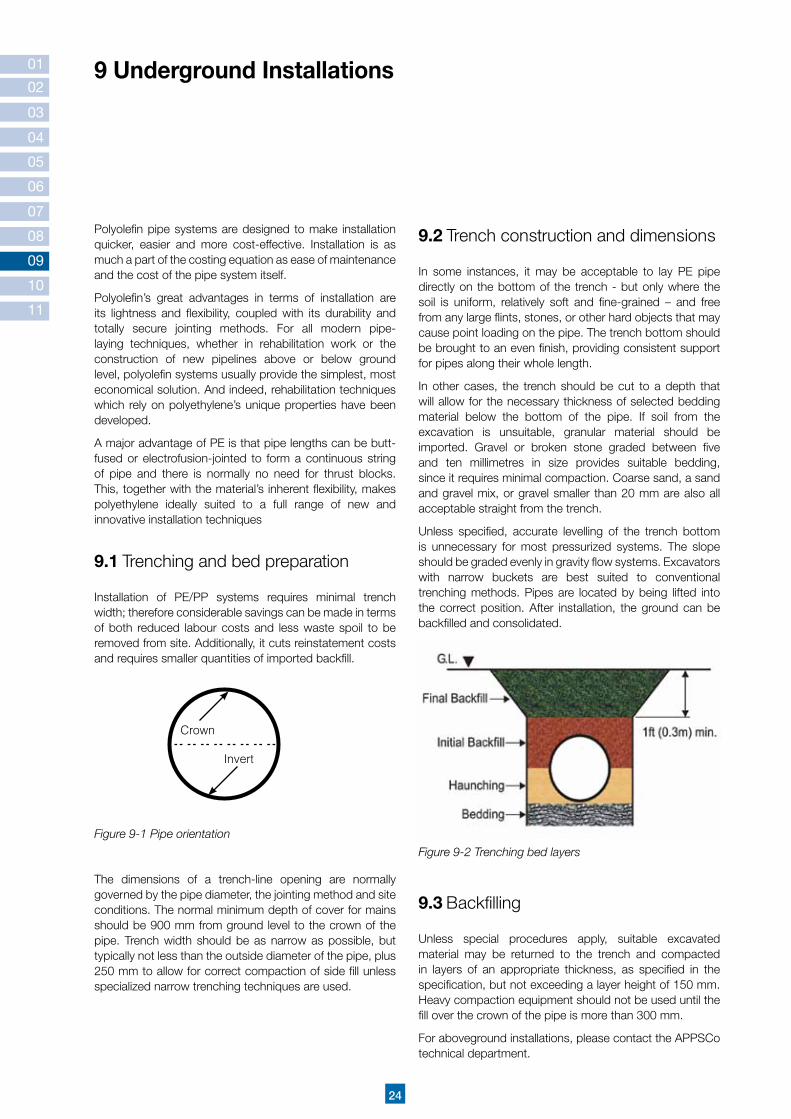
9.2 trench construction and dimensions
in some instances, it may be acceptable to lay PE pipe directly on the bottom of the trench - but only where the soil is uniform, relatively soft and fine-grained – and free from any large flints, stones, or other hard objects that may cause point loading on the pipe. The trench bottom should be brought to an even finish, providing consistent support for pipes along their whole length.
in other cases, the trench should be cut to a depth that will allow for the necessary thickness of selected bedding material below the bottom of the pipe. if soil from the excavation is unsuitable, granular material should be imported. Gravel or broken stone graded between five and ten millimetres in size provides suitable bedding, since it requires minimal compaction. Coarse sand, a sand and gravel mix, or gravel smaller than 20 mm are also all acceptable straight from the trench.
Unless specified, accurate levelling of the trench bottom is unnecessary for most pressurized systems. The slope should be graded evenly in gravity flow systems. Excavators with narrow buckets are best suited to conventional trenching methods. Pipes are located by being lifted into the correct position. After installation, the ground can be backfilled and consolidated.
Polyolefin pipe systems are designed to make installation quicker, easier and more cost-effective. installation is as much a part of the costing equation as ease of maintenance and the cost of the pipe system itself.
Polyolefin’s great advantages in terms of installation are its lightness and flexibility, coupled with its durability and totally secure jointing methods. For all modern pipe-laying techniques, whether in rehabilitation work or the construction of new pipelines above or below ground level, polyolefin systems usually provide the simplest, most economical solution. And indeed, rehabilitation techniques which rely on polyethylene’s unique properties have been developed.
A major advantage of PE is that pipe lengths can be butt-fused or electrofusion-jointed to form a continuous string of pipe and there is normally no need for thrust blocks. This, together with the material’s inherent flexibility, makes polyethylene ideally suited to a full range of new and innovative installation techniques
9.1 trenching and bed preparation
installation of PE/PP systems requires minimal trench width; therefore considerable savings can be made in terms of both reduced labour costs and less waste spoil to be removed from site. Additionally, it cuts reinstatement costs and requires smaller quantities of imported backfill.
Crown
Invert
Figure 9-1 Pipe orientation
The dimensions of a trench-line opening are normally governed by the pipe diameter, the jointing method and site conditions. The normal minimum depth of cover for mains should be 900 mm from ground level to the crown of the pipe. Trench width should be as narrow as possible, but typically not less than the outside diameter of the pipe, plus 250 mm to allow for correct compaction of side fill unless specialized narrow trenching techniques are used.
9 Underground Installations
9.3 Backfilling
Unless special procedures apply, suitable excavated material may be returned to the trench and compacted in layers of an appropriate thickness, as specified in the specification, but not exceeding a layer height of 150 mm. Heavy compaction equipment should not be used until the fill over the crown of the pipe is more than 300 mm.
For aboveground installations, please contact the APPSCo technical department.
Figure 9-2 Trenching bed layers

25
APPSCo thermoplastic pipe can be jointed using different methods. This includes jointing by:
Butt-fusion welding
Electrofusion welding
Compression coupling
Flange connection
10.1 Butt-fusion welding process
Polyethylene pipes may be produced, to be connected by means of the butt welding method, depending on the project. However there are limitations for using this jointing system, with regard to both diameter and wall thickness (figure 10-1) .
Connection by this welding method can be applied to diameters of between 50 mm and 1600 mm; and in relation to the diameter, to wall thicknesses from 5 mm to 100 mm. The butt-welding process is carried out in accordance with the DVS 2207 standard.
Attention should be paid to the following points when connecting PE pipes using the butt-welding method:
1 The temperature the welding environment should not be below 5° C or above 35° C.
2 The wall thickness of the pipes to be connected must be equal; if there is any difference, then such difference must not exceed 10%.
3 The ends of the two pipes to be welded are secured by the clamps of the welding machine. The end of the loose pipe or the pipe to be added to the pipeline should be placed in the movable hydraulic part of the machine.
Head sock pressure
Heating time with reduced pressure
Time
Pressure
Tim
e for
rem
ova
lof heatin
g m
irro
rInitialheatingtime under pressure
Pressurebuild-up time
Pressure level under initial heating and under joining and cooling
Cooling time
01
02
03
04
05
06
07
08
09
10
11
10 Pipe Joining
Figure 10-1 Illustration of the details during the welding
4 Secure the longitudinal movement of the free pipe by using adjustable rollers.
5 Prior to the welding process, welding surfaces must be scraped (using the planer by fixing it between the two ends to be welded), any oxidation removed and the welding surfaces must come into complete contact..

26
01
02
03
04
05
06
07
08
09
10
11
8 After this the bead will start forming, and then the cooling period will begin. During the weld cooling period, the connection pressure values of the pipes must be kept equal.
Table 10-1 Optimum welding times of HDPE pipes at 20°C environmental temperature
.................4.5 0.5 .................45.0 .................5.0 ................5.0 .................6.0
4.5..........7.0 1.0 45.0........70.0 5.0...........6.0 5.0.........6.0 6.0........10.0
7.0........12.0 1.5 70.0......120.0 6.0...........8.0 6.0.........8.0 10.0........16.0
12.0........19.0 2.0 120.0......190.0 8.0.........10.0 8.0.......11.0 16.0........24.0
19.0........26.0 2.5 190.0......260.0 10.0.........12.0 11.0.......14.0 24.0........32.0
26.0........37.0 3.0 260.0......370.0 12.0.........16.0 14.0.......19.0 32.0........45.0
37.0........50.0 3.5 370.0......500.0 16.0.........20.0 19.0.......25.0 45.0........60.0
50.0........70.0 4.0 500.0......700.0 20.0.........25.0 25.0.......35.0 60.0........80.0
Pipe wallthickness(mm)
Weldingpressure0.15 N/mm2
Bead height(mm)
Heat time0.02 N/mm2
(sec)
Heatingelementremovetime(sec)
Pipeconnectionpressureoperationtime (minutes)
Coolingtime(minutes)
6 Once the welding surface has been scraped, it must be protected from dirt and the pipe ends need to be cleaned. if there is any re-soiling, the scraping process must be repeated.
7 Fix the heating element, (temperature 200° C - 220° C), between the two pipe ends, keep the same hydraulic pressure for the duration of the heating up time, and then remove the heating element within a time frame equal to the release time.
Pipe welding calculation formula:
Apipe = ( da2 - di2 ) x π ( mm2 ) ______________
4
Welded compression force calculation
F = PSpecific × APipe (n)
veya ≈ dm × π × s ( mm2 )
Symbol Definition
Apipe Pipe welding area
da Outer diameter
di Inner diameter
dm Middle diameter
F Pressure surge
PE = 0.15 N/mm2 PSpecific PP = 0.10 N/mm2
Table 10-2 Symbol definition

27
10.2 Electrofusion welding process
Electrofusion welded joints of polyethylene pipes are made in accordance with international standard DVS 2207. Welding pipes with two different wall thicknesses are possible using this welding method. The electrofusion welding machines used for welding are light; they also facilitate welding with various welding parameters, and filling of the welding made, if necessary.
Using the electrofusion welding process, pipes made of the same raw material may be welded. The steps below must be followed before starting electrofusion welding:
1 The solution flow speed for HDPE electrofusion connection is 0.3.....1.7 gr/10 min (190° C/5kg). The solution flow speeds of pipes to be welded and the muff should be between these values. Pipes with the same solution flow speed may be welded.
2 The area in which welding is to take place must be weather-proofed. (For example, protected from snow, rain, wind, effective sunlight, etc.)
3 The temperature of the welding environment must be between 5° C and 50° C.
4 As all welding parameters are controlled by the site machine; the operator needs only to present the barcode (on the code card supplied with the coupling) to the machine’s reader and the machine setting will be done automatically.
5 The pressure test must be initialized at least one hour after the welding process is finished, once the pipes are completely cooled. The pressure test is done in accordance with Din 4279/1.To commence this procedure 1.5 x Pn. pressure is applied to the welded pipes. if this pressure value does not decrease,then the test has been passed.
The electrofusion welding procedure is as follows:
1 The entry limit is marked on the pipe, with the pipe edges to be welded – properly cut and smooth – placed inside the piece to be welded up to the ‘pipe leaning limit’ (i.e. the limit to which the pipes can lean).
01
02
03
04
05
06
07
08
09
10
11
2 The surface to be welded must be cleaned and any surface oxidation must be scraped offor to welding.
3 The pieces to be welded must be unpacked at the welding station. All electrofusion surfaces to be welded, on both pipe and fitting, must be cleaned with industrial alcohol, and once cleaned, they must not be touched.

28
01
02
03
04
05
06
07
08
09
10
11
Connection with butt welding
Steel flange Plunge + Nut
HDPE pipe
Connection with muffGasketFlange adapter
Figure 10-2 Flange connection
4 The electrofusion welding ends must be secured, once it has been checked that they are in a straight line with the pipe, with their ends facing upwards. The welding machine sockets are placed at the weld ends and prepared for welding.
10.3 Compression Coupling Joint
The pipes are connected to each other by means of coupling adaptor. Having been cut vertical to its axis, the pipe is inserted into the coupling up to the raised point. When both pipes are in position, the bolts are tightened by hand and the connection thus achieved. if the pipe diameter is 40 mm or higher, the bolts should be tightened using a special wrench rather than by hand. This joining method is not recommended for pipes with diameters exceeding 110 mm.
5 Once the ‘ready’ has been displayed by the machine, the welding process will start when the barcode is presented to the machine’s reader, or when the welding parameters are entered manually. Generally, welding machines display the welding time and voltage on the monitor.
10.4 Flange Connection
A flange joint connection is used for combining PE pipes with equipment such as steel pipes, valves, pumps, and condensers. it is also used in cases where the pipeline needs to be dismantled at a later stage, or for connecting PE pipes to different pipe materials. Steel rings, the flange/backing ring, and the flange adaptor are shown in figure 10-2 .
Stub ends are fixed on both ends of the PE pipes and connected with bolts and nuts. Do not torque the bolts in circular order, but in alternate rows. Do not pull on the pipelines while tightening the bolts, in order to prevent causing an overload on the structural elements that guide the pipes.

29
01
02
03
04
05
06
07
08
09
10
11
Polyolefin materials are flexible, lightweight and easy to handle. nevertheless, care should be taken not to cause scuffing or gouging of the surface.
11.1 Straight Lengths and Bundles
A flatbed vehicle, free from sharp objects and projections, should be used for the transportation of pipe systems. When lifting pipe bundles by crane, wideband slings should be used; do not use chains or hooks. For lengths of over 6 metres, load distributing beams should be inserted, spaced at equal distances.
Allow for a certain amount of deflection or slight bending of pipe bundles when loading or unloading. 6 metre bundles may be handled using a forklift, but longer lengths should be moved using a side loader of four supporting forks or by a crane with a load-distributing beam. individual lengths should be handled in a similar way. Skid timbers and rope slings can be used to ease unloading on site.
11.2 Coils
Small coils:
Small coils of pipe strapped onto pallets are easily handled by forklift. Large coils of 125 mm to 180 mm pipe will require lifting individually by forklift and can be lifted as shown in the following figures:
11 Handling and Storage
Figure 11-1 Pallet off-loading
Figure 11-2 Sample of large diameter coil truck loading
Figure 11-3 Lifting the coiled pipes with a crane and straps

01
02
03
04
05
06
07
08
09
10
11
Releasing coils:
Pipes held in coils are under high tension and must be strapped accordingly. These can be hazardous if released incorrectly, particularly if the end of the pipe is not kept restrained at all times. It is most important to read and understand the following guidelines before attempting to release coils. When uncoiling coiled pipes with an OD of more than 63 mm, care must be taken to prevent the straps being released suddenly, and the use of an uncoiling stand is recommended.
For outer bands with additional strapping of individual layers:
Do not remove any of these bands until the pipe is required for installation.
Remove them carefully, from the outmost layer first, so that only the length of pipe needed immediately is released.
Successive layers can be released by removing banding as the pipe is drawn away from the coil.
Never:
Drag or roll individual pipes or bundles.
Throw or drop the pipe or fitting from the delivery vehicle.
Use metal slings, hooks, or chains when handling.
Expose pipes or fittings to prolonged sunlight.
Stack more than three metres or three bundles high.
Place pipes or fittings in contact with lubricant or hydraulic oils, gasoline, solvents or other aggressive materials.
Always:
Examine the pipes carefully before installation and any damaged pipes.
Store pipes on flat, firm ground which is able to withstand the weight of the pipes and the lifting apparatus.
Stack the heaviest pipe at the bottom.
Anchor the load securely to prevent slippage. (As PE pipes have very smooth inner and outer surfaces. Be sure the unloading equipment is rated to handle the weight of the pipe).
Avoid excessive stacking heights and stack pipes in straight rows. Pipes can become distorted if they are not stored properly.
Unload one pallet, bundle, or strip load layer at a time. Truck straps securing a bundle or strip load layer should be released when that bundle or layer is to be unloaded.
Keep pipe/fittings well away from sharp objects. Use wide, non-metallic slings.
Exercise special care when handling pipes in wet conditions, since they may become slippery.
Keep protective packaging intact until the pipes/ fittings are required for use.
Keep pipes/fittings away from intense heat, except when jointing.
Allow for some bending deflection when pipes are loaded and unloaded. Lifting points should be evenly spaced.
30

31
12 Location Plan
AMIA
NTIT
GRO
UP O
F CO
MPA
NY G
RP A
ND P
E PL
ANT
- JED
DAH
21˚1
7’00
.71”
N
39˚1
1’10
.22”
E
AL-KHAIR BRIDGETO MAKKAH
ARAM
CO
TRAF
IC C
IRCL
E
WAR
EHO
USES
ARE
A
KING
FAI
SAL
NAVA
L BA
SE
TRAF
IC C
IRCL
E
18.5
0 km
CHEC
K PO
INT
TO SOUTH CORNICE
3.00
km
2.50
km
TRAF
IC C
IRCL
E
AL-M
AJAD
OUE
AL-R
AAJ
STEE
LCO
MPA
NY
TO A
L-KH
UMRA
N
وكم
را اأ
اةف
�صم
الشم
ل�ا
يوع
جدامل
ت
ياقل
لنل
�شتي
تفكز
مر
ك ملل
ة اعد
قاية
حرلب
ل ا�ش
في
يةثان
الة
حلملر
- ات
عاود
شتمل�
ة اين
مد

32
Note :

33
Note :

Distributed by:
AP
PS
Co
PG
V2,
10-
12
AMIANTIT PolyolefinPiping Systems Co.(APPSCo)P.O. Box 32262Jeddah 21451Phone : +966 2 692 94 31 +966 2 651 56 76Fax : +966 920004070 ext. 2444 +966 2 651 91 49
Utmost care has been taken to ensure that all the contents of this brochure are accurate. However, AMIANTIT and its subsidiaries do not accept responsibility for any problems which may arise as a result of errors in this publication. Therefore customers should make inquiries into the potential product supplier and convince themselves of the suitability of any products supplied or manufactured by AMIANTIT and/or its subsidiaries before using them.