Embed Size (px)
Citation preview
AMF PANEL
www.kzpower.com
www.kzpower.com
Life is Energy Energy is Life
AMF PANEL
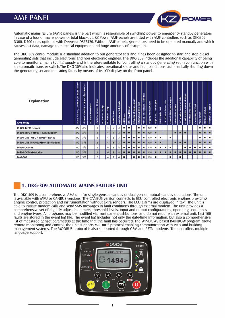
The DKG-309 is a comprehensive AMF unit for single genset standby or dual genset mutual standby operations. The unit is available with MPU or CANBUS versions. The CANBUS version connects to ECU controlled electronic engines providing engine control, protection and instrumentation without extra senders. The ECU alarms are displayed in text. The unit is able to initiate modem calls and send SMS messages in fault conditions through external modem. The unit provides a comprehensive set of digitally adjustable timers, threshold levels, input and output configurations, operating sequences and engine types. All programs may be modified via front panel pushbuttons, and do not require an external unit. Last 100 faults are stored in the event log file. The event log includes not only the date-time information, but also a comprehensive list of measured genset parameters at the time that the fault has occurred. The WINDOWS based RAINBOW program allows remote monitoring and control. The unit supports MODBUS protocol enabling communication with PLCs and building management systems. The MODBUS protocol is also supported through GSM and PSTN modems. The unit offers multiple language support.
1. DKG-309 AUTOMATIC MAINS FAILURE UNIT
Automatic mains failure (AMF) panels is the part which is responsible of switching power to emergency standby generators in case of a loss of mains power or total blackout. KZ Power AMF panels are fitted with AMF controllers such as DKG309, D300, D500 or as optional with Deepsea DSE7320. Without AMF panels, generators need to be operated manually and which causes lost data, damage to electrical equipment and huge amounts of disruption.
The DKG 309 conrol module is a standard addition to our generator sets and it has been designed to start and stop diesel generating sets that include electronic and non electronic engines. The DKG 309 includes the additional capability of being able to monitor a mains (utility) supply and is therefore suitable for controlling a standby generating set in conjunction with an automatic transfer switch.The DKG 309 also indicates perational status and fault conditions, automatically shutting down the generating set and indicating faults by means of its LCD display on the front panel.
1
Mai
ns t
ensi
on /
cur
rent
inpu
t ph
ase
num
ber
Gen
erat
or t
ensi
on /
cur
rent
pha
se n
umbe
r
No
pow
er o
n st
andb
y
Cont
acto
r ou
tput
s 16
Am
p
DC
outp
uts
10 A
mp
DC
outp
uts
1 Am
p
Dig
ital i
nput
s
Anal
ogue
sw
itich
inpu
ts
MPU
inpu
ts
J193
9 CA
NBU
S po
rt
Exte
nsio
n of
inpu
t/ou
tput
Inte
rnal
rea
l tim
e cl
ock
Wee
kly
run
sche
dule
/ A
uto
test
Logg
ing
with
tes
t va
lues
Logi
c /
RS-2
32 s
eria
l por
t
RS-4
85 s
eria
l por
t
10/1
00 M
B et
hern
et p
ort
Exte
rnal
GSM
mod
em s
uppo
rt
Inte
rnal
GSM
mod
em
SMS
send
ing
in c
ase
of f
ailu
re
E-m
ail s
endi
ng in
cas
e of
fai
lure
Embe
dded
web
ser
ver
Conn
ectin
g vi
a SN
MP
Wav
e sc
reen
Har
man
ic a
naly
se
Exte
rnal
GPS
sup
port
AMF Units
D-300 MPU + J1939 3/0 3/3 2 4 8 3 400
D-300 MPU + J1939 + GSM Modem 3/0 3/3 2 4 8 3 400
D-500-LITE MPU + J1939 + RS485 3/0 3/3 2 4 8 3 400
D-500-LITE MPU+J1939+485+Modem 3/0 3/3 2 4 8 3 400
D-500-COMM 3/0 3/3 2 6 8 4 400
D-500-COMM+Modem 3/0 3/3 2 6 8 4 400
DKG-309 3/0 3/3 2 4 7 4 100
True RMS measurementsECU connection through J1939 CAN optionJ1939 ECU warnings displayed as textMPU input optionDual genset mutual standby operationEvent logging with time stamp andmeasurementsBattery backed-up real time clockBuilt in daily / weekly / monthly exerciserWeekly operation schedule programsField adjustable parametersRS-232 serial portFree MS-Windows Remote monitoring SW
GSM and PSTN modem supportGSM SMS message sending on faultMODBUS communicationsMultiple language supportCustomer logo display capability16 Amp contactor outputs1 Amp DC semiconductor outputsConfigurable analogue inputs: 4Configurable digital inputs: 7Configurable digital outputs: 2Total digital outputs: 6I/O expansion capabilityPlug-in connection system
1.1 Features
Generator Volts: L1-N, L2-N, L3-NGenerator Volts: L1-L2, L2-L3, L3-L1Generator Amps: L1, L2, L3Generator KW: L1, L2, L3, totalGenerator pf: L1, L2, L3, totalGenerator FrequencyEngine rpmMains Volts: L1-N, L2-N, L3-NMains Volts: L1-L2, L2-L3, L3-L1Mains FrequencyBattery VoltageEngine Coolant TemperatureEngine Oil PressureFuel LevelEngine Oil Temperature
1.2 Measurements 1.3 Digital InputThe unit has 7 configurable digital inputs. Each input is fully configurable with selectable names, alarm type, polling, latching and contact type.
1.4 Analog InputEngine analog inputs are provided for coolant temperature, oil pressure, oil temperature and fuel level. The inputs have programmable sensor characteristics so that they are suitable for any type and brand of sensors. 1.5 OutputThe unit provides 2 relay and 4 semiconductor outputs. 2 of them have programmable functions, selectable from a list. Any function or alarm condition may be a digital output. Using two Relay Expan-sion Modules, the number of relays may be increased to 22, 16 of them being volt-free contacts.
1.6 Event LoggingThe unit records last 100 events with date-time stamp and a total of 18 measured parameters.
1.7 Telemetry and Remote ProgrammingThe unit provides the user with large telemetry facilities via its standard RS-232 serial port, connecting either to a PC, PLC or a GSM or PSTN modem. It supports both RAINBOW and MODBUS communication protocols. The standard PC software offers local and modem operation capabilities as well as modem networking feature.
The PC program is used for below purposes: Parameter upload/download Remote monitoring and control Diagnostics and analysis
1.8 TECHNICAL SPECIFICATIONS
2
Alternator voltage: 0 to 300 V-AC (Ph-N)Alternator frequency: 0-100 Hz.Mains voltage: 0 to 300 V-AC (Ph-N)Mains frequency: 0-100 Hz.V-A-cos Accuracy: 1.0% + 1 digitkW-kVA-kVAr Accuracy: 2.0% + 1 digitDC Supply Range: 9.0 to 33.0 V-DCCranking dropouts: survives 0 V for 100ms.Typical Standby Current: 100 mA-DCMaximum Operating Current: 200 mA-DC (Relay outputs open)Generator/Mains Contactor Relay Outputs: 16 A / 250VDC Outputs: 1A @ 28V protected semiconductor outputCharge excitation: min 2 WattsMagnetic pickup input:: 0.5 – 30 V-AC.Magnetic pickup frequency: 10 KHz max.Current inputs: from CTs, .../5A. Max load 0.7VA per phase.Analog input range: 0-5000 ohms.Serial port: RS-232, 9600 bauds, no parity, 1 bit stopOperating temp.: -20OC (-4OF) to 70OC (158OF).Storage temp.: -40OC (-40OF) to 80OC (176OF).Maximum humidity: 95% non-condensing.Dimensions: 172 x 134 x 46 mm (WxHxD)Panel Cut-out Dimensions: 151x111 mm minimum.Weight: 340 g (approx.)Case Material: High Temperature ABS/PC (UL94-V0)IP Protection: IP65 from front panel, IP30 from the rearInstallation: Flat surface mounting on a Type 1 Enclosure. Rear retaining plastic brackets.CE Conformity reference standards: EN 61010 (safety requirements) EN 61326 (EMC requirements)UL / CSA Conformity: certificate # 20110527-E314374 UL 508, Edition 17 UL 2200, 1st Edition. UL 840 Edition 3 CSA C22.2 NO. 14 - Edition 10
OilPressureSender
CoolantTemp.Sender
FUSE
FUSE
FUSE Mains
ContactorGeneratorContactor
M���S�������
�������
��TE���TO�
FUSE
� � � � �
Electrical��nterloc�
� � ��
�emote�Monitorin�and�Pro�ram�Port
FUSE
�atter����������
������
StarterMotor
Cran�Fuel
��
������
�� ���� �� ��
OilPressure
�i��Temperature
Emer�enc�Stop
Spare��
Spare��
������ ����
Fuel�e�elSender
C�ar�e�lt.
��
�� ���� ��
MPUor
�����
�O�������� �
�atter��ne�ati�e�must��e��rounded.
+
��G����
�� �� ����
FUSE
FUSE
��
OilTemp.Sender
�� ��
Pro�ram�oc�
Coolant�e�el
��
�ecti�ierFail
��
�nput�Output�E�tension�Port
�����
AMF PANEL
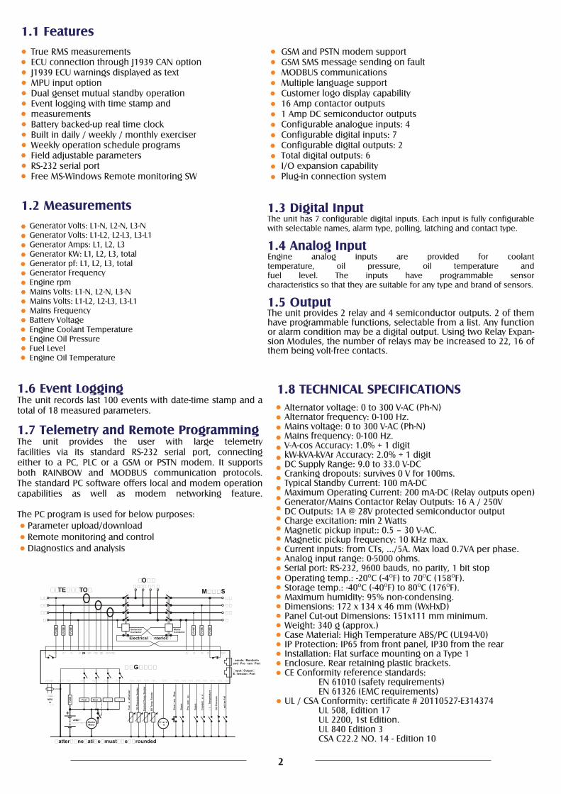
The D-300 is a cost effective comprehensive genset controller ready for internet monitoring.
2. DKG-300
2.1. Features
2.2 Measurements
Diesel and gas genset support400Hz operation support400 event logs, full snapshotAll parameters front panel editable3 level configuration password128x64 graphical LCD displayDownloadable languagesWaveform display of V & IHarmonic analysis of V & I16Amp MCB & GCB outputs8 configurable digital inputs6 configurable digital outputs3 configurable analog inputsBoth CANBUS-J1939 & MPU3 configurable service alarmsMultiple automatic exerciserWeekly operation scheduleDual mutual standby with equal aging of gensetsManual “speed fine adjust” on selected ECUsAutomatic fuel pump controlDisable protections featureExcess power protectionReverse power protectionOverload IDMT protectionLoad shedding, dummy loadMultiple load managementCurrent unbalance protectionVoltage unbalance protection
Fuel filling & fuel theft alarmsBattery back-up real time clockIdle speed controlBattery charge run enabledCombat mode supportMultiple nominal conditionsContactor & MCB drive4 quadrant genset power countersMains power countersFuel filling counterFuel consumption counterModem diagnostics displayConfigurable through USB, RS-232 and GPRSFree configuration programAllows SMS controlsReady for central monitoringMobile genset supportAutomatic GSM geo-locationGPS connectivity (RS232)Easy USB firmware upgradeIP65 rating with optional gasket
Mains & genset PN/PP voltagesMains & genset frequencyMains & genset phase currentsMains & genset neutral currentsMains & genset, phase & total,kW, kVA, kVAr, pfEngine speedBattery voltage
3
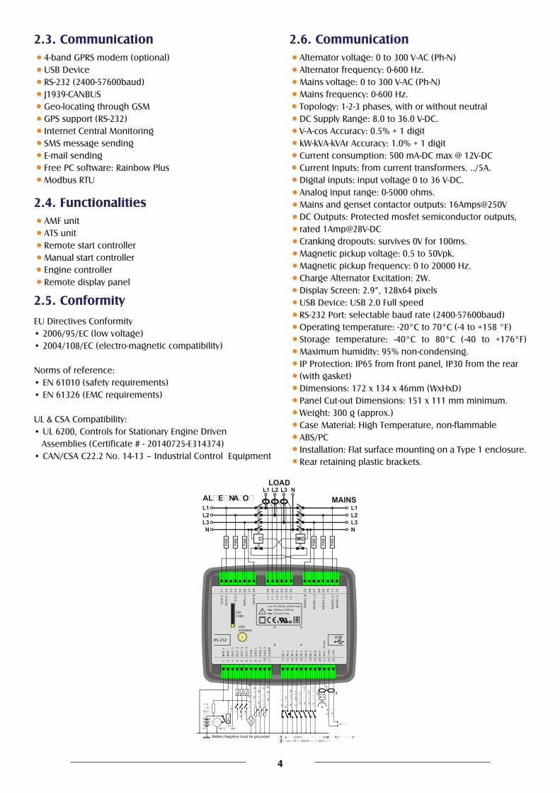
2.3. Communication 2.6. Communication
2.4. Functionalities
2.5. Conformity
4-band GPRS modem (optional)USB DeviceRS-232 (2400-57600baud)J1939-CANBUSGeo-locating through GSMGPS support (RS-232)Internet Central MonitoringSMS message sendingE-mail sendingFree PC software: Rainbow PlusModbus RTU
Alternator voltage: 0 to 300 V-AC (Ph-N)Alternator frequency: 0-600 Hz.Mains voltage: 0 to 300 V-AC (Ph-N)Mains frequency: 0-600 Hz.Topology: 1-2-3 phases, with or without neutralDC Supply Range: 8.0 to 36.0 V-DC.V-A-cos Accuracy: 0.5% + 1 digitkW-kVA-kVAr Accuracy: 1.0% + 1 digitCurrent consumption: 500 mA-DC max @ 12V-DCCurrent Inputs: from current transformers. ../5A.Digital inputs: input voltage 0 to 36 V-DC.Analog input range: 0-5000 ohms.Mains and genset contactor outputs: 16Amps@250VDC Outputs: Protected mosfet semiconductor outputs,rated 1Amp@28V-DCCranking dropouts: survives 0V for 100ms.Magnetic pickup voltage: 0.5 to 50Vpk.Magnetic pickup frequency: 0 to 20000 Hz.Charge Alternator Excitation: 2W.Display Screen: 2.9”, 128x64 pixelsUSB Device: USB 2.0 Full speedRS-232 Port: selectable baud rate (2400-57600baud)Operating temperature: -20°C to 70°C (-4 to +158 °F)Storage temperature: -40°C to 80°C (-40 to +176°F) Maximum humidity: 95% non-condensing.IP Protection: IP65 from front panel, IP30 from the rear(with gasket)Dimensions: 172 x 134 x 46mm (WxHxD)Panel Cut-out Dimensions: 151 x 111 mm minimum.Weight: 300 g (approx.)Case Material: High Temperature, non-flammableABS/PCInstallation: Flat surface mounting on a Type 1 enclosure. Rear retaining plastic brackets.
EU Directives Conformity• 2006/95/EC (low voltage)• 2004/108/EC (electro-magnetic compatibility)
Norms of reference:• EN 61010 (safety requirements)• EN 61326 (EMC requirements)
UL & CSA Compatibility:• UL 6200, Controls for Stationary Engine Driven Assemblies (Certificate # - 20140725-E314374)• CAN/CSA C22.2 No. 14-13 – Industrial Control Equipment
AMF unitATS unitRemote start controllerManual start controllerEngine controllerRemote display panel
USBRS-232
21 3 4 5 6 7 8 9 10 11 12 13 14 15 16 17 18 19 20 21 22 23
BA
T +
BA
T -
OU
T 1
OU
T 2
OU
T 3
OU
T 4
CH
G
IN 1
IN 2
IN 3
IN 4
IN 5
IN 6
IN 7
IN 8
SG
ND
SN
D 1
SN
D 2
SN
D 3
MP
U+
MP
U- /
PG
ND
CA
NH
CA
NL
6463 6765 66 68 69 70 71 72
3+ 3-I I
MA
INS
-N
MA
INS
-L3
MA
INS
-L2
MA
INS
-L1
MA
INS
-C
51 52 53 54 55 56 57 58 62616059
GE
N-N
GE
N-L
3
G-L
2
GE
N-L
1G
EN
-C
I1+ 1- 2+ 2-I I I
SIMCARD
GSMANTENNA
8 to 36Vdc, 500mA max
! 300Vac, 0-600 Hz0.2 to 6.0 Aac
MAINSL1L2L3N
LOADL3 N
FUSEMC
FUSE
FUSE
FUSE
FUSE
FUSE
L1L2L3N
AL�E�NA�O�L1 L2
�C
A
22
V
tat oto
a
Aam
a
A
t
at
o
o
H
m
m
c
to
o
oo
a
t
a
t
a
t
at
oct to t od, co to t d.
�2od om o d o.
3
-H
3-
�2
o
a
t 2
a
t 3
d
d �1
m
.
d
.
d
.
d
M�U
�1
�2
4
AMF PANEL
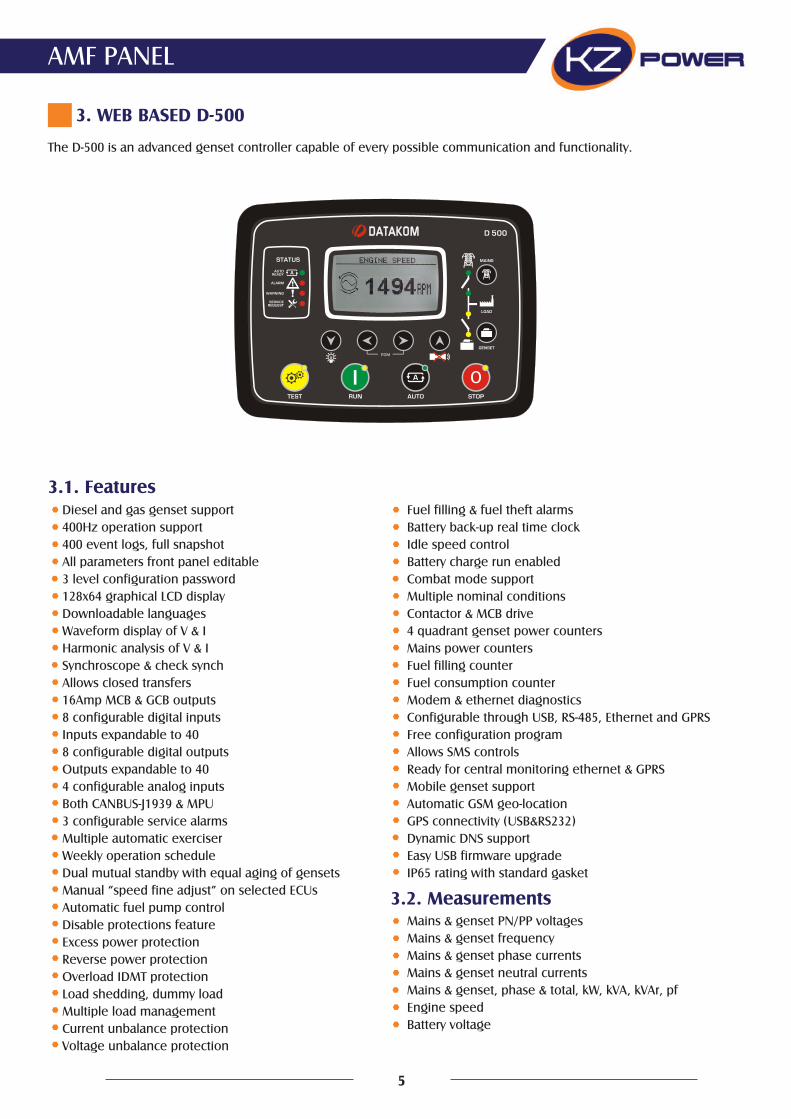
The D-500 is an advanced genset controller capable of every possible communication and functionality.
3. WEB BASED D-500
3.1. Features
3.2. Measurements
Diesel and gas genset support400Hz operation support400 event logs, full snapshotAll parameters front panel editable3 level configuration password128x64 graphical LCD displayDownloadable languagesWaveform display of V & IHarmonic analysis of V & ISynchroscope & check synchAllows closed transfers16Amp MCB & GCB outputs8 configurable digital inputsInputs expandable to 408 configurable digital outputsOutputs expandable to 404 configurable analog inputsBoth CANBUS-J1939 & MPU3 configurable service alarmsMultiple automatic exerciserWeekly operation scheduleDual mutual standby with equal aging of gensetsManual “speed fine adjust” on selected ECUsAutomatic fuel pump controlDisable protections featureExcess power protectionReverse power protectionOverload IDMT protectionLoad shedding, dummy loadMultiple load managementCurrent unbalance protectionVoltage unbalance protection
Fuel filling & fuel theft alarmsBattery back-up real time clockIdle speed controlBattery charge run enabledCombat mode supportMultiple nominal conditionsContactor & MCB drive4 quadrant genset power countersMains power countersFuel filling counterFuel consumption counterModem & ethernet diagnosticsConfigurable through USB, RS-485, Ethernet and GPRSFree configuration programAllows SMS controlsReady for central monitoring ethernet & GPRSMobile genset supportAutomatic GSM geo-locationGPS connectivity (USB&RS232)Dynamic DNS supportEasy USB firmware upgradeIP65 rating with standard gasket
Mains & genset PN/PP voltagesMains & genset frequencyMains & genset phase currentsMains & genset neutral currentsMains & genset, phase & total, kW, kVA, kVAr, pfEngine speedBattery voltage
5
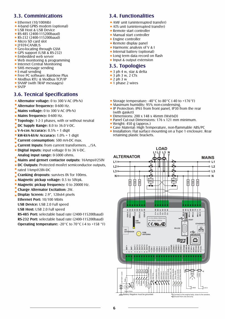
3.3. Comminications 3.4. Functionalities
3.5. Topologies
3.6. Tecnical Specifications
Ethernet (10/100Mb)4-band GPRS modem (optional)USB Host & USB DeviceRS-485 (2400-115200baud)RS-232 (2400-115200baud)Micro SD card slotJ1939-CANBUSGeo-locating through GSMGPS support (USB & RS-232)Embedded web serverWeb monitoring & programmingInternet Central MonitoringSMS message sendingE-mail sendingFree PC software: Rainbow PlusModbus RTU & Modbus TCP/IPSNMP (with TRAP messages)SNTP
AMF unit (uninterrupted transfer)ATS unit (uninterrupted transfer)Remote start controllerManual start controllerEngine controllerRemote display panelHarmonic analysis of V & IInternal battery (optional)Long term data record on flashInput & output extension
3 ph 4 w, star & delta3 ph 3 w, 2 CTs2 ph 3 w1 phase 2 wires
Alternator voltage: 0 to 300 V-AC (Ph-N)Alternator frequency: 0-600 Hz.Mains voltage: 0 to 300 V-AC (Ph-N)Mains frequency: 0-600 Hz.Topology: 1-2-3 phases, with or without neutralDC Supply Range: 8.0 to 36.0 V-DC.V-A-cos Accuracy: 0.5% + 1 digitkW-kVA-kVAr Accuracy: 1.0% + 1 digitCurrent consumption: 500 mA-DC max.Current Inputs: from current transformers. ../5A.Digital inputs: input voltage 0 to 36 V-DC.Analog input range: 0-5000 ohms.Mains and genset contactor outputs: 16Amps@250VDC Outputs: Protected mosfet semiconductor outputs,rated 1Amp@28V-DCCranking dropouts: survives 0V for 100ms.Magnetic pickup voltage: 0.5 to 50Vpk.Magnetic pickup frequency: 0 to 20000 Hz.Charge Alternator Excitation: 2W.Display Screen: 2.9”, 128x64 pixelsEthernet Port: 10/100 MbitsUSB Device: USB 2.0 Full speedUSB Host: USB 2.0 Full speedRS-485 Port: selectable baud rate (2400-115200baud)RS-232 Port: selectable baud rate (2400-115200baud)Operating temperature: -20°C to 70°C (-4 to +158 °F)
Storage temperature: -40°C to 80°C (-40 to +176°F)Maximum humidity: 95% non-condensing.IP Protection: IP65 from front panel, IP30 from the rear(with gasket)Dimensions: 200 x 148 x 46mm (WxHxD)Panel Cut-out Dimensions: 176 x 121 mm minimum.Weight: 450 g (approx.)Case Material: High Temperature, non-flammable ABS/PCInstallation: Flat surface mounting on a Type 1 enclosure. Rear retaining plastic brackets.
6

KZ ENERJI COZUMLERI ve DIS TIC. LTD. STI.Mimar Sinan Mah. Bosna Caddesi No : 1/6 Cek-mekoy / Istanbul / TurkeyT: +90 216 641 96 43 (pbx) M : +90 532 255 76 77 F : +90 216 641 96 47w w w . k z p o w e r . c o mi n f o @ k z p o w e r . c o m


![Allied Telesis Management Framework (AMF)forum.alliedtelesis.ru/MY/Presentations/2016/AlliedTelesis_AMF_Demo_ru.pdf · Allied Telesis Management Framework (AMF) [ ] AMF Member AMF](https://img.pdfslide.us/doc/110x75/5e88bb8ee2fad2109a7792f5/allied-telesis-management-framework-amfforum-allied-telesis-management-framework.jpg)