Embed Size (px)
Citation preview
AM(F)-CC-JORE Field Discharge ContactorsField Circuit Breakers
France page : 2 / 6 Note : DTD 2011 12
Breaking characteristics: Contactor with two poles in series:
Type 63-21 125-21 200-21 500-21 Max. Breaking Capacity
500V dc with L/R = 5 ms
1.2 kA 2 kA 3.5 kA 7 kA
M. B. C. 600V dc with L/R = 5 ms
1.2 kA 2 kA 3.5 kA 7 kA
M. B. C. 900V dc with L/R = 5 ms
1 kA 1.6 kA 2.6 kA 6 kA
M. B. C. 1 500V dc with L/R = 5 ms
800 A 1.4 kA 2 kA 5 kA
Contactor with three poles in series:
Type 63-31 125-31 200-31 500-31 M. B. C. 600V dc
with L/R = 5 ms 1.2 kA 2 kA 3.5 kA 7 kA
M. B. C.1 000V dc with L/R = 5 ms
1.2 kA 2 kA 3.5 kA 7 kA
M. B. C. 1 500V dc with L/R = 5 ms
1 kA 1.6 kA 2.6 kA 6.5 kA
M. B. C. 2 250V dc with L/R = 5 ms
800 A 1.4 kA 2 kA 5 kA
Making characteristics:
Type 63 125 200 500 Max. Making Capacity 1.3 kA 2.4 kA 4 kA 9 kA
Icc max in closed position
1.4 kA 2.5 kA 4.5 kA 10 kA
Auxiliary contact characteristics: Operational Current
Type Rated thermal
current
(Ith in A) Type of current
Operational voltage (V)
24/48 110/127 220/230 380/400 440/550
CA 12
12
AC-15 8 8 5 3 2 DC-13
L / R = 15 ms 5 3 1.5 0.75 0.5
CA 15 15 AC-15 10 10 6 3.5 2.5 DC-13
L / R = 15 ms 9 3 1.5 0.75 0.5
CARB 6 AC-15 5 4 3 2 1 DC-13
L / R = 15 ms 3 1.5 0.4 0.1 -
France page : 3 / 6 Note : DTD 2011 12
TECHNICAL DATA
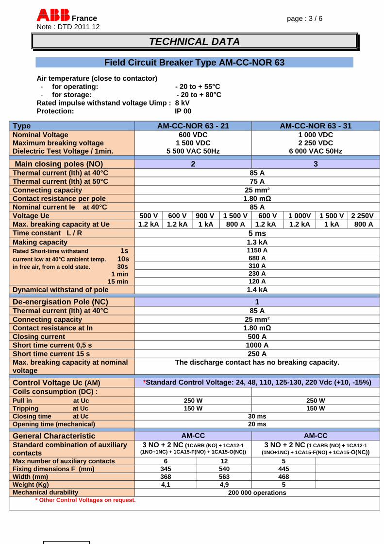
Field Circuit Breaker Type AM-CC-NOR 63 Air temperature (close to contactor) - for operating: - 20 to + 55°C - for storage: - 20 to + 80°C
Rated impulse withstand voltage Uimp : 8 kV Protection: IP 00
Type AM-CC-NOR 63 - 21 AM-CC-NOR 63 - 31 Nominal Voltage Maximum breaking voltage Dielectric Test Voltage / 1min.
600 VDC 1 500 VDC
5 500 VAC 50Hz
1 000 VDC 2 250 VDC
6 000 VAC 50Hz
Main closing poles (NO) 2 3 Thermal current (Ith) at 40°C 85 A Thermal current (Ith) at 50°C 75 A Connecting capacity 25 mm² Contact resistance per pole 1.80 mΩ Nominal current Ie at 40°C 85 A Voltage Ue 500 V 600 V 900 V 1 500 V 600 V 1 000V 1 500 V 2 250V Max. breaking capacity at Ue 1.2 kA 1.2 kA 1 kA 800 A 1.2 kA 1.2 kA 1 kA 800 A Time constant L / R 5 ms Making capacity 1.3 kA Rated Short-time withstand 1s current Icw at 40°C ambient temp. 10s in free air, from a cold state. 30s 1 min 15 min
1150 A 680 A 310 A 230 A 120 A
Dynamical withstand of pole 1.4 kA
De-energisation Pole (NC) 1 Thermal current (Ith) at 40°C 85 A Connecting capacity 25 mm² Contact resistance at In 1.80 mΩ Closing current 500 A Short time current 0,5 s 1000 A Short time current 15 s 250 A Max. breaking capacity at nominal voltage
The discharge contact has no breaking capacity.
Control Voltage Uc (AM) *Standard Control Voltage: 24, 48, 110, 125-130, 220 Vdc (+10, -15%) Coils consumption (DC) : Pull in at Uc 250 W 250 W Tripping at Uc 150 W 150 W Closing time at Uc 30 ms Opening time (mechanical) 20 ms
General Characteristic AM-CC AM-CC Standard combination of auxiliary contacts
3 NO + 2 NC (1CARB (NO) + 1CA12-1 (1NO+1NC) + 1CA15-F(NO) + 1CA15-O(NC))
3 NO + 2 NC (1 CARB (NO) + 1CA12-1 (1NO+1NC) + 1CA15-F(NO) + 1CA15-O(NC))
Max number of auxiliary contacts 6 12 5 Fixing dimensions F (mm) 345 540 445 Width (mm) 368 563 468 Weight (Kg) 4,1 4,9 5 Mechanical durability 200 000 operations * Other Control Voltages on request.
France page : 4 / 6 Note : DTD 2011 12
TECHNICAL DATA
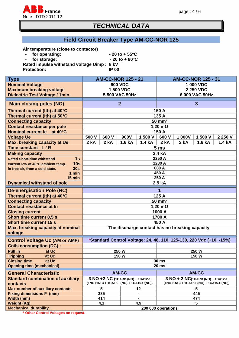
Field Circuit Breaker Type AM-CC-NOR 125
Air temperature (close to contactor) - for operating: - 20 to + 55°C - for storage: - 20 to + 80°C
Rated impulse withstand voltage Uimp : 8 kV Protection: IP 00
Type AM-CC-NOR 125 - 21 AM-CC-NOR 125 - 31 Nominal Voltage Maximum breaking voltage Dielectric Test Voltage / 1min.
600 VDC 1 500 VDC
5 500 VAC 50Hz
1 000 VDC 2 250 VDC
6 000 VAC 50Hz
Main closing poles (NO) 2 3
Thermal current (Ith) at 40°C 150 A Thermal current (Ith) at 50°C 135 A Connecting capacity 50 mm² Contact resistance per pole 1,20 mΩ Nominal current Ie at 40°C 150 A Voltage Ue 500 V 600 V 900V 1 500 V 600 V 1 000V 1 500 V 2 250 V Max. breaking capacity at Ue 2 kA 2 kA 1.6 kA 1.4 kA 2 kA 2 kA 1.6 kA 1.4 kA Time constant L / R 5 ms Making capacity 2.4 kA Rated Short-time withstand 1s current Icw at 40°C ambient temp. 10s in free air, from a cold state. 30s 1 min 15 min
2250 A 1280 A 680 A 450 A 250 A
Dynamical withstand of pole 2.5 kA
De-energisation Pole (NC) 1 Thermal current (Ith) at 40°C 125 A Connecting capacity 50 mm² Contact resistance at In 1,20 mΩ Closing current 1000 A Short time current 0,5 s 1700 A Short time current 15 s 450 A Max. breaking capacity at nominal voltage
The discharge contact has no breaking capacity.
Control Voltage Uc (AM or AMF) *Standard Control Voltage: 24, 48, 110, 125-130, 220 Vdc (+10, -15%) Coils consumption (DC) : Pull in at Uc 250 W 250 W Tripping at Uc 150 W 150 W Closing time at Uc 30 ms Opening time (mechanical) 20 ms
General Characteristic AM-CC AM-CC Standard combination of auxiliary contacts
3 NO +2 NC (1CARB (NO) + 1CA12-1 (1NO+1NC) + 1CA15-F(NO) + 1CA15-O(NC))
3 NO + 2 NC(1CARB (NO) + 1CA12-1 (1NO+1NC) + 1CA15-F(NO) + 1CA15-O(NC))
Max number of auxiliary contacts 5 12 5 Fixing dimensions F (mm) 385 - 445 Width (mm) 414 - 474 Weight (Kg) 4,1 4,9 5 Mechanical durability 200 000 operations
* Other Control Voltages on request.
France page : 5 / 6 Note : DTD 2011 12
TECHNICAL DATA
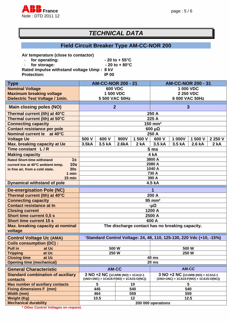
Field Circuit Breaker Type AM-CC-NOR 200 Air temperature (close to contactor) - for operating: - 20 to + 55°C - for storage: - 20 to + 80°C
Rated impulse withstand voltage Uimp : 8 kV Protection: IP 00
Type AM-CC-NOR 200 - 21 AM-CC-NOR 200 - 31 Nominal Voltage Maximum breaking voltage Dielectric Test Voltage / 1min.
600 VDC 1 500 VDC
5 500 VAC 50Hz
1 000 VDC 2 250 VDC
6 000 VAC 50Hz
Main closing poles (NO) 2 3
Thermal current (Ith) at 40°C 250 A Thermal current (Ith) at 50°C 225 A Connecting capacity 150 mm² Contact resistance per pole 600 μΩ Nominal current Ie at 40°C 250 A Voltage Ue 500 V 600 V 900V 1 500 V 600 V 1 000V 1 500 V 2 250 VMax. breaking capacity at Ue 3.5kA 3.5 kA 2.6kA 2 kA 3.5 kA 3.5 kA 2.6 kA 2 kA Time constant L / R 5 ms Making capacity 4 kA Rated Short-time withstand 1s current Icw at 40°C ambient temp. 10s in free air, from a cold state. 30s 1 min 15 min
3800 A 2080 A 1040 A 730 A 390 A
Dynamical withstand of pole 4.5 kA
De-energisation Pole (NC) 1 Thermal current (Ith) at 40°C 200 A Connecting capacity 95 mm² Contact resistance at In -μΩ Closing current 1200 A Short time current 0,5 s 2500 A Short time current 15 s 600 A Max. breaking capacity at nominal voltage
The discharge contact has no breaking capacity.
Control Voltage Uc (AMA) *Standard Control Voltage: 24, 48, 110, 125-130, 220 Vdc (+10, -15%) Coils consumption (DC) : Pull in at Uc 500 W 500 W Tripping at Uc 250 W 250 W Closing time at Uc 40 ms Opening time (mechanical) 20 ms
General Characteristic AM-CC AM-CC
Standard combination of auxiliary contacts
3 NO +2 NC (1CARB (NO) + 1CA12-1 (1NO+1NC) + 1CA15-F(NO) + 1CA15-O(NC))
3 NO +2 NC (1CARB (NO) + 1CA12-1 (1NO+1NC) + 1CA15-F(NO) + 1CA15-O(NC))
Max number of auxiliary contacts 5 10 5 Fixing dimensions F (mm) 445 540 540 Width (mm) 464 559 559 Weight (Kg) 10.5 12 12.5 Mechanical durability 200 000 operations
* Other Control Voltages on request.
France page : 6 / 6 Note : DTD 2011 12
TECHNICAL DATA
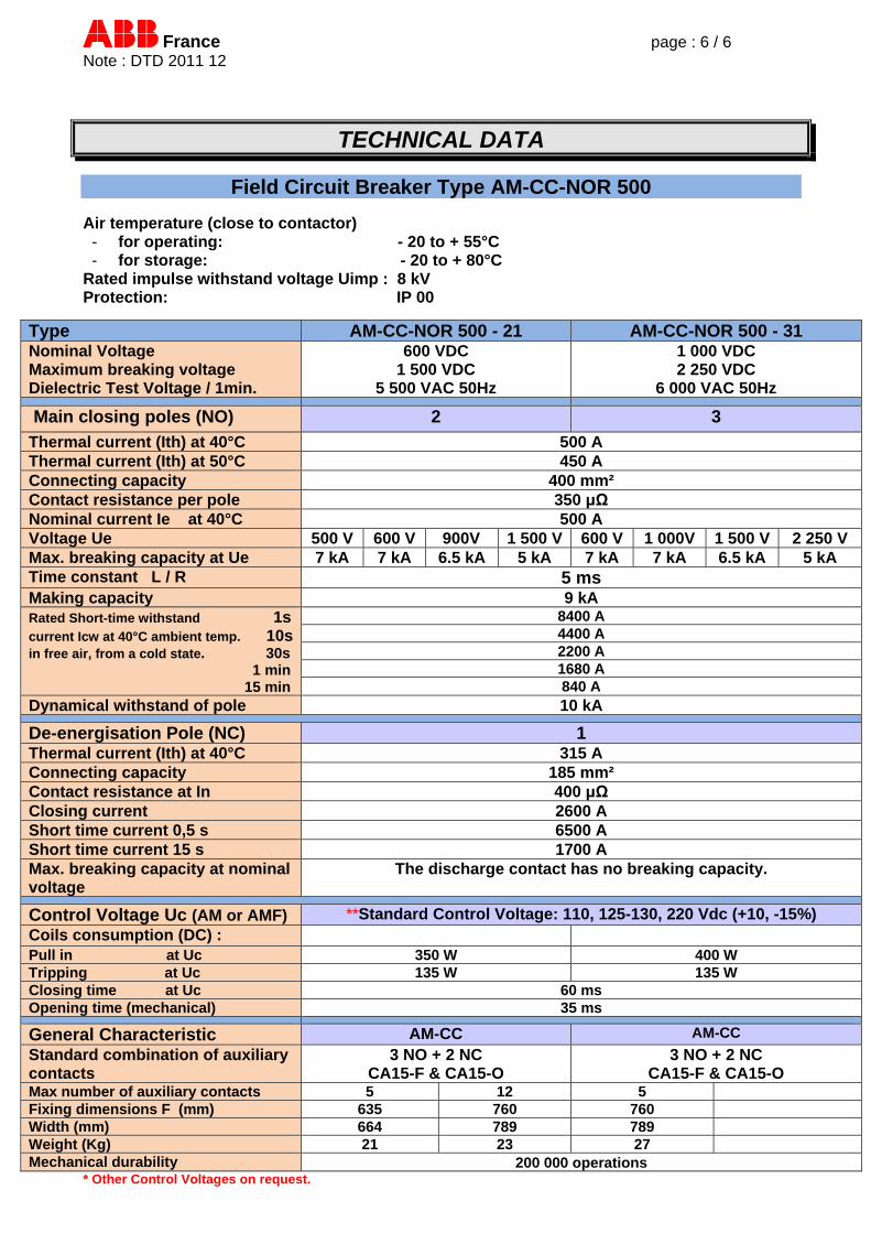
Field Circuit Breaker Type AM-CC-NOR 500 Air temperature (close to contactor) - for operating: - 20 to + 55°C - for storage: - 20 to + 80°C
Rated impulse withstand voltage Uimp : 8 kV Protection: IP 00
Type AM-CC-NOR 500 - 21 AM-CC-NOR 500 - 31 Nominal Voltage Maximum breaking voltage Dielectric Test Voltage / 1min.
600 VDC 1 500 VDC
5 500 VAC 50Hz
1 000 VDC 2 250 VDC
6 000 VAC 50Hz
Main closing poles (NO) 2 3
Thermal current (Ith) at 40°C 500 A Thermal current (Ith) at 50°C 450 A Connecting capacity 400 mm² Contact resistance per pole 350 μΩ Nominal current Ie at 40°C 500 A Voltage Ue 500 V 600 V 900V 1 500 V 600 V 1 000V 1 500 V 2 250 V Max. breaking capacity at Ue 7 kA 7 kA 6.5 kA 5 kA 7 kA 7 kA 6.5 kA 5 kA Time constant L / R 5 ms Making capacity 9 kA Rated Short-time withstand 1s current Icw at 40°C ambient temp. 10s in free air, from a cold state. 30s 1 min 15 min
8400 A 4400 A 2200 A 1680 A 840 A
Dynamical withstand of pole 10 kA
De-energisation Pole (NC) 1 Thermal current (Ith) at 40°C 315 A Connecting capacity 185 mm² Contact resistance at In 400 μΩ Closing current 2600 A Short time current 0,5 s 6500 A Short time current 15 s 1700 A Max. breaking capacity at nominal voltage
The discharge contact has no breaking capacity.
Control Voltage Uc (AM or AMF) **Standard Control Voltage: 110, 125-130, 220 Vdc (+10, -15%) Coils consumption (DC) : Pull in at Uc 350 W 400 W Tripping at Uc 135 W 135 W Closing time at Uc 60 ms Opening time (mechanical) 35 ms
General Characteristic AM-CC AM-CC
Standard combination of auxiliary contacts
3 NO + 2 NC CA15-F & CA15-O
3 NO + 2 NC CA15-F & CA15-O
Max number of auxiliary contacts 5 12 5 Fixing dimensions F (mm) 635 760 760 Width (mm) 664 789 789 Weight (Kg) 21 23 27 Mechanical durability 200 000 operations
* Other Control Voltages on request.
France page : 2 / 12 Note : DTD 201112
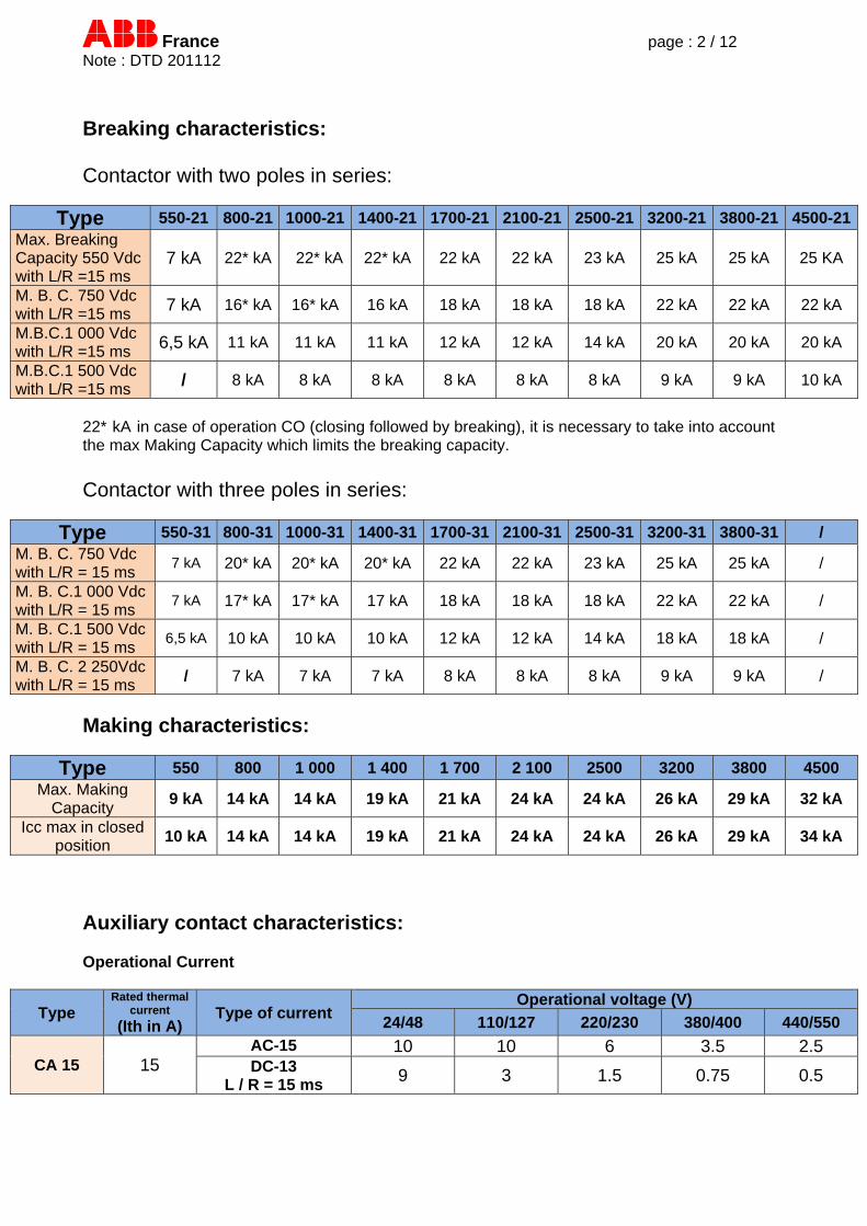
Breaking characteristics: Contactor with two poles in series:
Type 550-21 800-21 1000-21 1400-21 1700-21 2100-21 2500-21 3200-21 3800-21 4500-21Max. Breaking Capacity 550 Vdc with L/R =15 ms
7 kA 22* kA 22* kA 22* kA 22 kA 22 kA 23 kA 25 kA 25 kA 25 KA
M. B. C. 750 Vdc with L/R =15 ms 7 kA 16* kA 16* kA 16 kA 18 kA 18 kA 18 kA 22 kA 22 kA 22 kA
M.B.C.1 000 Vdc with L/R =15 ms 6,5 kA 11 kA 11 kA 11 kA 12 kA 12 kA 14 kA 20 kA 20 kA 20 kA
M.B.C.1 500 Vdc with L/R =15 ms / 8 kA 8 kA 8 kA 8 kA 8 kA 8 kA 9 kA 9 kA 10 kA
22* kA in case of operation CO (closing followed by breaking), it is necessary to take into account the max Making Capacity which limits the breaking capacity.
Contactor with three poles in series:
Type 550-31 800-31 1000-31 1400-31 1700-31 2100-31 2500-31 3200-31 3800-31 / M. B. C. 750 Vdc with L/R = 15 ms
7 kA 20* kA 20* kA 20* kA 22 kA 22 kA 23 kA 25 kA 25 kA /
M. B. C.1 000 Vdc with L/R = 15 ms
7 kA 17* kA 17* kA 17 kA 18 kA 18 kA 18 kA 22 kA 22 kA /
M. B. C.1 500 Vdc with L/R = 15 ms
6,5 kA 10 kA 10 kA 10 kA 12 kA 12 kA 14 kA 18 kA 18 kA /
M. B. C. 2 250Vdc with L/R = 15 ms
/ 7 kA 7 kA 7 kA 8 kA 8 kA 8 kA 9 kA 9 kA /
Making characteristics:
Type 550 800 1 000 1 400 1 700 2 100 2500 3200 3800 4500 Max. Making
Capacity 9 kA 14 kA 14 kA 19 kA 21 kA 24 kA 24 kA 26 kA 29 kA 32 kA
Icc max in closed position
10 kA 14 kA 14 kA 19 kA 21 kA 24 kA 24 kA 26 kA 29 kA 34 kA
Auxiliary contact characteristics: Operational Current
Type Rated thermal
current
(Ith in A) Type of current
Operational voltage (V)
24/48 110/127 220/230 380/400 440/550
CA 15 15 AC-15 10 10 6 3.5 2.5 DC-13
L / R = 15 ms 9 3 1.5 0.75 0.5
France page : 3 / 12 Note : DTD 201112
TECHNICAL DATA
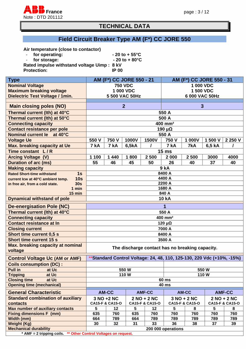
Field Circuit Breaker Type AM (F*) CC JORE 550 Air temperature (close to contactor) - for operating: - 20 to + 55°C - for storage: - 20 to + 80°C
Rated impulse withstand voltage Uimp : 8 kV Protection: IP 00
Type AM (F*) CC JORE 550 - 21 AM (F*) CC JORE 550 - 31 Nominal Voltage Maximum breaking voltage Dielectric Test Voltage / 1min.
750 VDC 1 000 VDC
5 500 VAC 50Hz
1 000 VDC 1 500 VDC
6 000 VAC 50Hz
Main closing poles (NO) 2 3 Thermal current (Ith) at 40°C 550 A Thermal current (Ith) at 50°C 500 A Connecting capacity 400 mm² Contact resistance per pole 190 μΩ Nominal current Ie at 40°C 550 A Voltage Ue 550 V 750 V 1000V 1500V 750 V 1 000V 1 500 V 2 250 VMax. breaking capacity at Ue 7 kA 7 kA 6,5kA / 7 kA 7kA 6,5 kA / Time constant L / R 15 ms Arcing Voltage (V) 1 100 1 440 1 800 2 500 2 000 2 500 3000 4000 Duration of arc (ms) 55 46 45 50 26 40 37 40 Making capacity 9 kA Rated Short-time withstand 1s current Icw at 40°C ambient temp. 10s in free air, from a cold state. 30s 1 min 15 min
8400 A 4400 A 2200 A 1680 A 840 A
Dynamical withstand of pole 10 kA
De-energisation Pole (NC) 1 Thermal current (Ith) at 40°C 550 A Connecting capacity 400 mm² Contact resistance at In 120 μΩ Closing current 7000 A Short time current 0,5 s 8400 A Short time current 15 s 3500 A Max. breaking capacity at nominal voltage
The discharge contact has no breaking capacity.
Control Voltage Uc (AM or AMF) **Standard Control Voltage: 24, 48, 110, 125-130, 220 Vdc (+10%, -15%)Coils consumption (DC) : Pull in at Uc 550 W 550 W Tripping at Uc 110 W 110 W Closing time at Uc 60 ms Opening time (mechanical) 40 ms
General Characteristic AM-CC AMF-CC AM-CC AMF-CC Standard combination of auxiliary contacts
3 NO +2 NC CA15-F & CA15-O
2 NO + 2 NC CA15-F & CA15-O
3 NO + 2 NC CA15-F & CA15-O
2 NO + 2 NC CA15-F & CA15-O
Max number of auxiliary contacts 5 12 5 12 5 8 5 8 Fixing dimensions F (mm) 635 760 635 760 760 760 760 760 Width (mm) 664 789 664 789 789 789 789 789 Weight (Kg) 30 32 31 33 36 38 37 39 Mechanical durability 200 000 operations * AMF = 2 tripping coils. ** Other Control Voltages on request.
France page : 4 / 12 Note : DTD 201112
TECHNICAL DATA
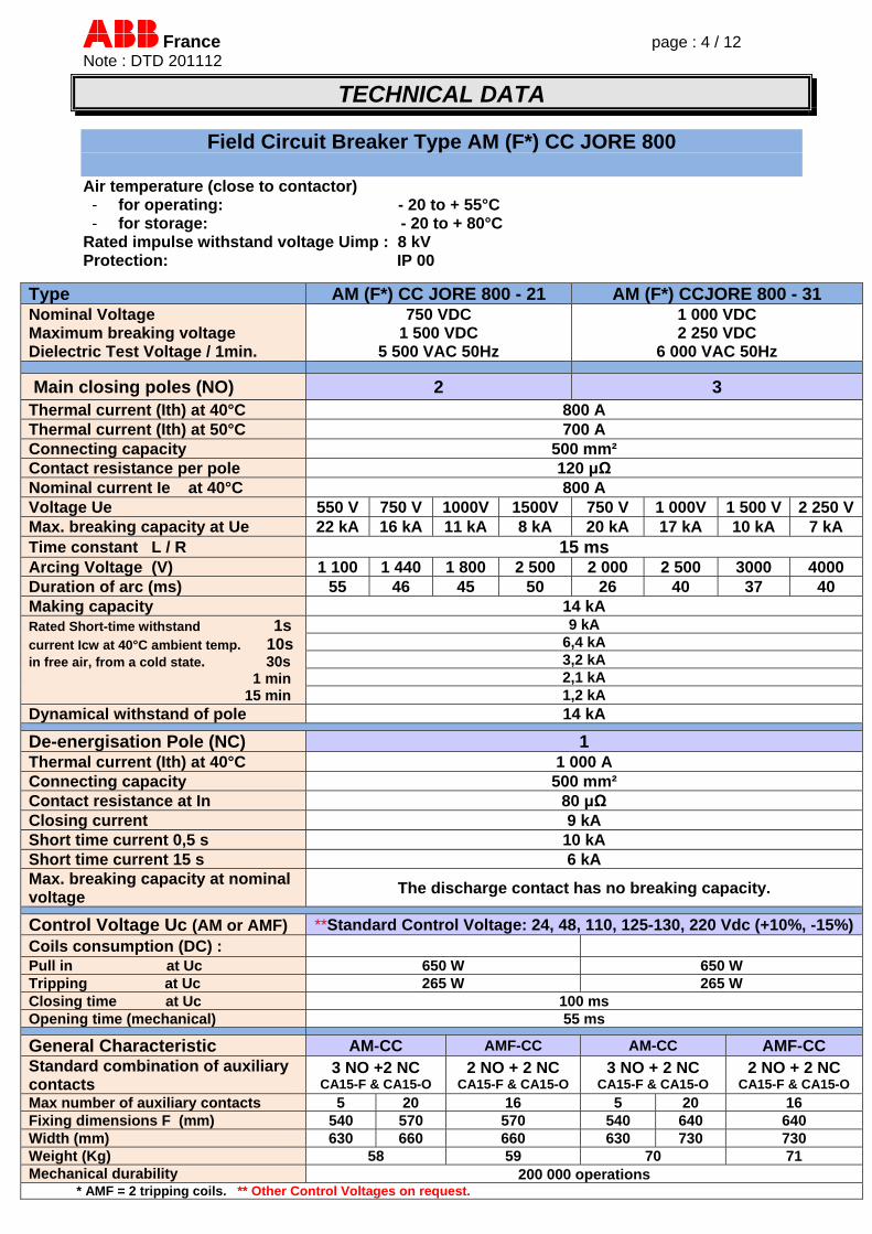
Field Circuit Breaker Type AM (F*) CC JORE 800
Air temperature (close to contactor) - for operating: - 20 to + 55°C - for storage: - 20 to + 80°C
Rated impulse withstand voltage Uimp : 8 kV Protection: IP 00
Type AM (F*) CC JORE 800 - 21 AM (F*) CCJORE 800 - 31 Nominal Voltage Maximum breaking voltage Dielectric Test Voltage / 1min.
750 VDC 1 500 VDC
5 500 VAC 50Hz
1 000 VDC 2 250 VDC
6 000 VAC 50Hz
Main closing poles (NO) 2 3 Thermal current (Ith) at 40°C 800 A Thermal current (Ith) at 50°C 700 A Connecting capacity 500 mm² Contact resistance per pole 120 μΩ Nominal current Ie at 40°C 800 A Voltage Ue 550 V 750 V 1000V 1500V 750 V 1 000V 1 500 V 2 250 VMax. breaking capacity at Ue 22 kA 16 kA 11 kA 8 kA 20 kA 17 kA 10 kA 7 kA Time constant L / R 15 ms Arcing Voltage (V) 1 100 1 440 1 800 2 500 2 000 2 500 3000 4000 Duration of arc (ms) 55 46 45 50 26 40 37 40 Making capacity 14 kA Rated Short-time withstand 1s current Icw at 40°C ambient temp. 10s in free air, from a cold state. 30s 1 min 15 min
9 kA 6,4 kA 3,2 kA 2,1 kA 1,2 kA
Dynamical withstand of pole 14 kA
De-energisation Pole (NC) 1 Thermal current (Ith) at 40°C 1 000 A Connecting capacity 500 mm² Contact resistance at In 80 μΩ Closing current 9 kA Short time current 0,5 s 10 kA Short time current 15 s 6 kA Max. breaking capacity at nominal voltage
The discharge contact has no breaking capacity.
Control Voltage Uc (AM or AMF) **Standard Control Voltage: 24, 48, 110, 125-130, 220 Vdc (+10%, -15%)Coils consumption (DC) : Pull in at Uc 650 W 650 W Tripping at Uc 265 W 265 W Closing time at Uc 100 ms Opening time (mechanical) 55 ms
General Characteristic AM-CC AMF-CC AM-CC AMF-CC Standard combination of auxiliary contacts
3 NO +2 NC CA15-F & CA15-O
2 NO + 2 NC CA15-F & CA15-O
3 NO + 2 NC CA15-F & CA15-O
2 NO + 2 NC CA15-F & CA15-O
Max number of auxiliary contacts 5 20 16 5 20 16 Fixing dimensions F (mm) 540 570 570 540 640 640 Width (mm) 630 660 660 630 730 730 Weight (Kg) 58 59 70 71 Mechanical durability 200 000 operations * AMF = 2 tripping coils. ** Other Control Voltages on request.
France page : 5 / 12 Note : DTD 201112
TECHNICAL DATA
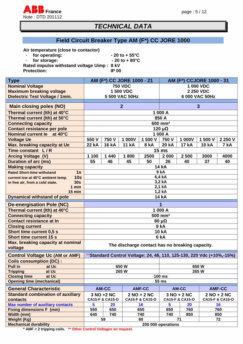
Field Circuit Breaker Type AM (F*) CC JORE 1000
Air temperature (close to contactor) - for operating: - 20 to + 55°C - for storage: - 20 to + 80°C
Rated impulse withstand voltage Uimp : 8 kV Protection: IP 00
Type AM (F*) CC JORE 1000 - 21 AM (F*) CCJORE 1000 - 31 Nominal Voltage Maximum breaking voltage Dielectric Test Voltage / 1min.
750 VDC 1 500 VDC
5 500 VAC 50Hz
1 000 VDC 2 250 VDC
6 000 VAC 50Hz
Main closing poles (NO) 2 3 Thermal current (Ith) at 40°C 1 000 A Thermal current (Ith) at 50°C 850 A Connecting capacity 600 mm² Contact resistance per pole 120 μΩ Nominal current Ie at 40°C 1 000 A Voltage Ue 550 V 750 V 1 000V 1 500 V 750 V 1 000V 1 500 V 2 250 VMax. breaking capacity at Ue 22 kA 16 kA 11 kA 8 kA 20 kA 17 kA 10 kA 7 kA Time constant L / R 15 ms Arcing Voltage (V) 1 100 1 440 1 800 2500 2 000 2 500 3000 4000 Duration of arc (ms) 55 46 45 50 26 40 37 40 Making capacity 14 kA Rated Short-time withstand 1s current Icw at 40°C ambient temp. 10s in free air, from a cold state. 30s 1 min 15 min
9 kA 6,4 kA 3,2 kA 2,1 kA 1,2 kA
Dynamical withstand of pole 14 kA
De-energisation Pole (NC) 1 Thermal current (Ith) at 40°C 1 000 A Connecting capacity 500 mm² Contact resistance at In 80 μΩ Closing current 9 kA Short time current 0,5 s 10 kA Short time current 15 s 6 kA Max. breaking capacity at nominal voltage
The discharge contact has no breaking capacity.
Control Voltage Uc (AM or AMF) **Standard Control Voltage: 24, 48, 110, 125-130, 220 Vdc (+10%,-15%)Coils consumption (DC) : Pull in at Uc 650 W 650 W Tripping at Uc 265 W 265 W Closing time at Uc 100 ms Opening time (mechanical) 55 ms
General Characteristic AM-CC AMF-CC AM-CC AMF-CC Standard combination of auxiliary contacts
3 NO +2 NC CA15-F & CA15-O
2 NO + 2 NC CA15-F & CA15-O
3 NO + 2 NC CA15-F & CA15-O
2 NO + 2 NC CA15-F & CA15-O
Max number of auxiliary contacts 5 20 16 5 20 16 Fixing dimensions F (mm) 550 650 650 650 760 760 Width (mm) 640 740 740 740 850 850 Weight (Kg) 59 60 71 72 Mechanical durability 200 000 operations
* AMF = 2 tripping coils. ** Other Control Voltages on request.

France page : 6 / 12 Note : DTD 201112
TECHNICAL DATA
Field Circuit Breaker Type AM (F*) CC JORE 1400 Air temperature (close to contactor) - for operating: - 20 to + 55°C - for storage: - 20 to + 80°C
Rated impulse withstand voltage Uimp : 8 kV Protection: IP 00
Type AM (F*) CC JORE 1400 - 21 AM (F*) CCJORE 1400 - 31 Nominal Voltage Maximum breaking voltage Dielectric Test Voltage / 1min.
750 VDC 1 500 VDC
5 500 VAC 50Hz
1 000 VDC 2 250 VDC
6 000 VAC 50Hz
Main closing poles (NO) 2 3
Thermal current (Ith) at 40°C 1 300 A Thermal current (Ith) at 50°C 1 200 A Connecting capacity 800 mm² Contact resistance per pole 100 μΩ Nominal current Ie at 40°C 1 300 A Voltage Ue 550 V 750 V 1 000V 1 500 V 750 V 1 000V 1 500 V 2 250 VMax. breaking capacity at Ue 22 kA 16 kA 11 kA 8 kA 20 kA 17 kA 10 kA 7 kA Time constant L / R 15 ms Arcing Voltage (V) 1 100 1 440 1 800 2500 2 000 2 500 3000 4000 Duration of arc (ms) 55 46 45 50 26 40 37 40 Making capacity 19 kA Rated Short-time withstand 1s current Icw at 40°C ambient temp. 10s in free air, from a cold state. 30s 1 min 15 min
11 kA 9 kA 5 kA
3,6 kA 1,9 kA
Dynamical withstand of pole 19 kA
De-energisation Pole (NC) 1 Thermal current (Ith) at 40°C 1 000 A Connecting capacity 500 mm² Contact resistance at In 80 μΩ Closing current 9 kA Short time current 0,5 s 10 kA Short time current 15 s 6 kA Max. breaking capacity at nominal voltage
The discharge contact has no breaking capacity.
Control Voltage Uc (AM or AMF) **Standard Control Voltage: 110, 125-130, 220 Vdc (+10, -15%) Coils consumption (DC) : Pull in at Uc 650 W 950 W Tripping at Uc 265 W 265 W Closing time at Uc 100 ms Opening time (mechanical) 50 ms
General Characteristic AM-CC AMF-CC AM-CC AMF-CC Standard combination of auxiliary contacts
3 NO +2 NC CA15-F & CA15-O
2 NO + 2 NC CA15-F & CA15-O
3 NO + 2 NC CA15-F & CA15-O
2 NO + 2 NC CA15-F & CA15-O
Max number of auxiliary contacts 5 20 16 5 20 16 Fixing dimensions F (mm) 550 650 650 650 760 760 Width (mm) 640 740 740 740 850 850 Weight (Kg) 60 61 72 73 Mechanical durability 200 000 operations
* AMF = 2 tripping coils. ** Other Control Voltages on request.
France page : 7 / 12 Note : DTD 201112
TECHNICAL DATA
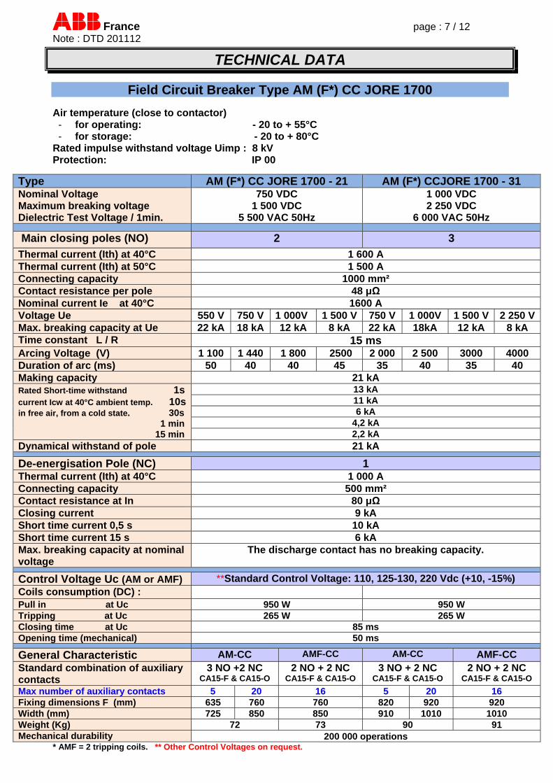
Field Circuit Breaker Type AM (F*) CC JORE 1700 Air temperature (close to contactor) - for operating: - 20 to + 55°C - for storage: - 20 to + 80°C
Rated impulse withstand voltage Uimp : 8 kV Protection: IP 00
Type AM (F*) CC JORE 1700 - 21 AM (F*) CCJORE 1700 - 31 Nominal Voltage Maximum breaking voltage Dielectric Test Voltage / 1min.
750 VDC 1 500 VDC
5 500 VAC 50Hz
1 000 VDC 2 250 VDC
6 000 VAC 50Hz
Main closing poles (NO) 2 3
Thermal current (Ith) at 40°C 1 600 A Thermal current (Ith) at 50°C 1 500 A Connecting capacity 1000 mm² Contact resistance per pole 48 μΩ Nominal current Ie at 40°C 1600 A Voltage Ue 550 V 750 V 1 000V 1 500 V 750 V 1 000V 1 500 V 2 250 VMax. breaking capacity at Ue 22 kA 18 kA 12 kA 8 kA 22 kA 18kA 12 kA 8 kA Time constant L / R 15 ms Arcing Voltage (V) 1 100 1 440 1 800 2500 2 000 2 500 3000 4000 Duration of arc (ms) 50 40 40 45 35 40 35 40 Making capacity 21 kA Rated Short-time withstand 1s current Icw at 40°C ambient temp. 10s in free air, from a cold state. 30s 1 min 15 min
13 kA 11 kA 6 kA
4,2 kA 2,2 kA
Dynamical withstand of pole 21 kA
De-energisation Pole (NC) 1 Thermal current (Ith) at 40°C 1 000 A Connecting capacity 500 mm² Contact resistance at In 80 μΩ Closing current 9 kA Short time current 0,5 s 10 kA Short time current 15 s 6 kA Max. breaking capacity at nominal voltage
The discharge contact has no breaking capacity.
Control Voltage Uc (AM or AMF) **Standard Control Voltage: 110, 125-130, 220 Vdc (+10, -15%) Coils consumption (DC) : Pull in at Uc 950 W 950 W Tripping at Uc 265 W 265 W Closing time at Uc 85 ms Opening time (mechanical) 50 ms
General Characteristic AM-CC AMF-CC AM-CC AMF-CC Standard combination of auxiliary contacts
3 NO +2 NC CA15-F & CA15-O
2 NO + 2 NC CA15-F & CA15-O
3 NO + 2 NC CA15-F & CA15-O
2 NO + 2 NC CA15-F & CA15-O
Max number of auxiliary contacts 5 20 16 5 20 16 Fixing dimensions F (mm) 635 760 760 820 920 920 Width (mm) 725 850 850 910 1010 1010 Weight (Kg) 72 73 90 91 Mechanical durability 200 000 operations
* AMF = 2 tripping coils. ** Other Control Voltages on request.

France page : 8 / 12 Note : DTD 201112
TECHNICAL DATA
Field Circuit Breaker Type AM (F*) CC JORE 2100 Air temperature (close to contactor) - for operating: - 20 to + 55°C - for storage: - 20 to + 80°C
Rated impulse withstand voltage Uimp : 8 kV Protection: IP 00
Type AM (F*) CC JORE 2100 - 21 AM (F*) CCJORE 2100 - 31 Nominal Voltage Maximum breaking voltage Dielectric Test Voltage / 1min.
750 VDC 1 500 VDC
5 500 VAC 50Hz
1 000 VDC 2 250 VDC
6 000 VAC 50Hz
Main closing poles (NO) 2 3
Thermal current (Ith) at 40°C 2 000 A Thermal current (Ith) at 50°C 1 750 A Connecting capacity 1500 mm² Contact resistance per pole 32 μΩ Nominal current Ie at 40°C 2 000 A Voltage Ue 550 V 750 V 1 000V 1 500 V 750 V 1 000V 1 500 V 2 250 VMax. breaking capacity at Ue 22 kA 18 kA 12 kA 8 kA 22 kA 18kA 12 kA 8 kA Time constant L / R 15 ms Arcing Voltage (V) 1 100 1 440 1 800 2500 2 000 2 500 3000 4000 Duration of arc (ms) 50 40 40 45 35 40 35 40 Making capacity 24 kA Rated Short-time withstand 1s current Icw at 40°C ambient temp. 10s in free air, from a cold state. 30s 1 min 15 min
15 kA 12 kA 7 kA
4,6 kA 2,6 kA
Dynamical withstand of pole 24 kA
De-energisation Pole (NC) 1 Thermal current (Ith) at 40°C 1 000 A Connecting capacity 500 mm² Contact resistance at In 80 μΩ Closing current 9 kA Short time current 0,5 s 10 kA Short time current 15 s 6 kA Max. breaking capacity at nominal voltage
The discharge contact has no breaking capacity.
Control Voltage Uc (AM or AMF) **Standard Control Voltage: 110, 125-130, 220 Vdc (+10, -15%) Coils consumption (DC) : Pull in at Uc 950 W 950 W Tripping at Uc 265 W 265 W Closing time at Uc 85 ms Opening time (mechanical) 45 ms
General Characteristic AM-CC AMF-CC AM-CC AMF-CC Standard combination of auxiliary contacts
3 NO +2 NC CA15-F & CA15-O
2 NO + 2 NC CA15-F & CA15-O
3 NO + 2 NC CA15-F & CA15-O
2 NO + 2 NC CA15-F & CA15-O
Max number of auxiliary contacts 5 20 16 5 20 16 Fixing dimensions F (mm) 635 760 760 820 920 920 Width (mm) 725 850 850 910 1010 1010 Weight (Kg) 80 81 100 101 Mechanical durability 200 000 operations
* AMF = 2 tripping coils. ** Other Control Voltages on request.

France page : 9 / 12 Note : DTD 201112
TECHNICAL DATA
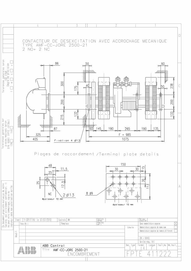
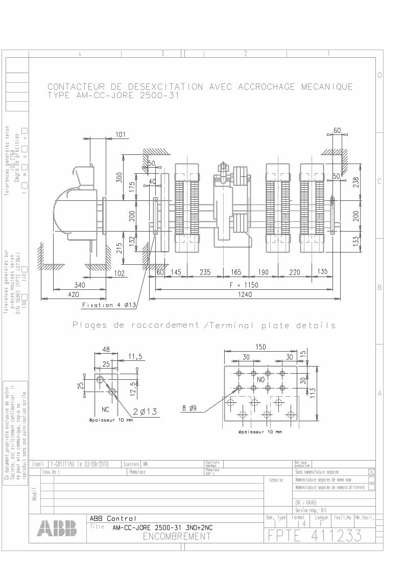
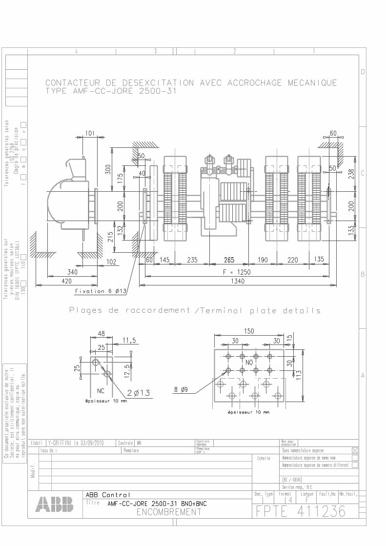
Field Circuit Breaker Type AM (F*) CC JORE 2500 Air temperature (close to contactor) - for operating: - 20 to + 55°C - for storage: - 20 to + 80°C
Rated impulse withstand voltage Uimp : 8 kV Protection: IP 00
Type AM (F*) CC JORE 2500 - 21 AM (F*) CCJORE 2500 - 31 Nominal Voltage Maximum breaking voltage Dielectric Test Voltage / 1min.
750 VDC 1 500 VDC
5 500 VAC 50Hz
1 000 VDC 2 250 VDC
6 000 VAC 50Hz
Main closing poles (NO) 2 3
Thermal current (Ith) at 40°C 2 300 A Thermal current (Ith) at 50°C 2 100 A Connecting capacity 2000 mm² Contact resistance per pole 55 μΩ Nominal current Ie at 40°C 2 300 A Voltage Ue 550 V 750 V 1 000V 1 500 V 750 V 1 000V 1 500 V 2 250 VMax. breaking capacity at Ue 23 kA 18 kA 14 kA 8 kA 23 kA 18kA 14 kA 8 kA Time constant L / R 15 ms Arcing Voltage (V) 1 100 1 440 1 800 2500 2 000 2 500 3000 4000 Duration of arc (ms) 50 40 40 45 35 40 35 40 Making capacity 24 kA Rated Short-time withstand 1s current Icw at 40°C ambient temp. 10s in free air, from a cold state. 30s 1 min 15 min
20 kA 15 kA 8 kA 6 kA 3 kA
Dynamical withstand of pole 24 kA
De-energisation Pole (NC) 1 Thermal current (Ith) at 40°C 1 000 A Connecting capacity 500 mm² Contact resistance at In 80 μΩ Closing current 9 kA Short time current 0,5 s 10 kA Short time current 15 s 6 kA Max. breaking capacity at nominal voltage
The discharge contact has no breaking capacity.
Control Voltage Uc (AM or AMF) **Standard Control Voltage: 110, 125-130, 220 Vdc (+10, -15%) Coils consumption (DC) : Pull in at Uc 950 W 950 W Tripping at Uc 265 W 265 W Closing time at Uc 85 ms Opening time (mechanical) 50 ms
General Characteristic AM-CC AMF-CC AM-CC AMF-CC Standard combination of auxiliary contacts
3 NO +2 NC CA15-F & CA15-O
2 NO + 2 NC CA15-F & CA15-O
3 NO + 2 NC CA15-F & CA15-O
2 NO + 2 NC CA15-F & CA15-O
Max number of auxiliary contacts 5 20 16 5 20 16 Fixing dimensions F (mm) 885 985 985 1050 1150 1150 Width (mm) 975 1075 1075 1140 1240 1240 Weight (Kg) 85 86 110 111 Mechanical durability 200 000 operations
* AMF = 2 tripping coils. ** Other Control Voltages on request.
France page : 10 / 12 Note : DTD 201112
TECHNICAL DATA
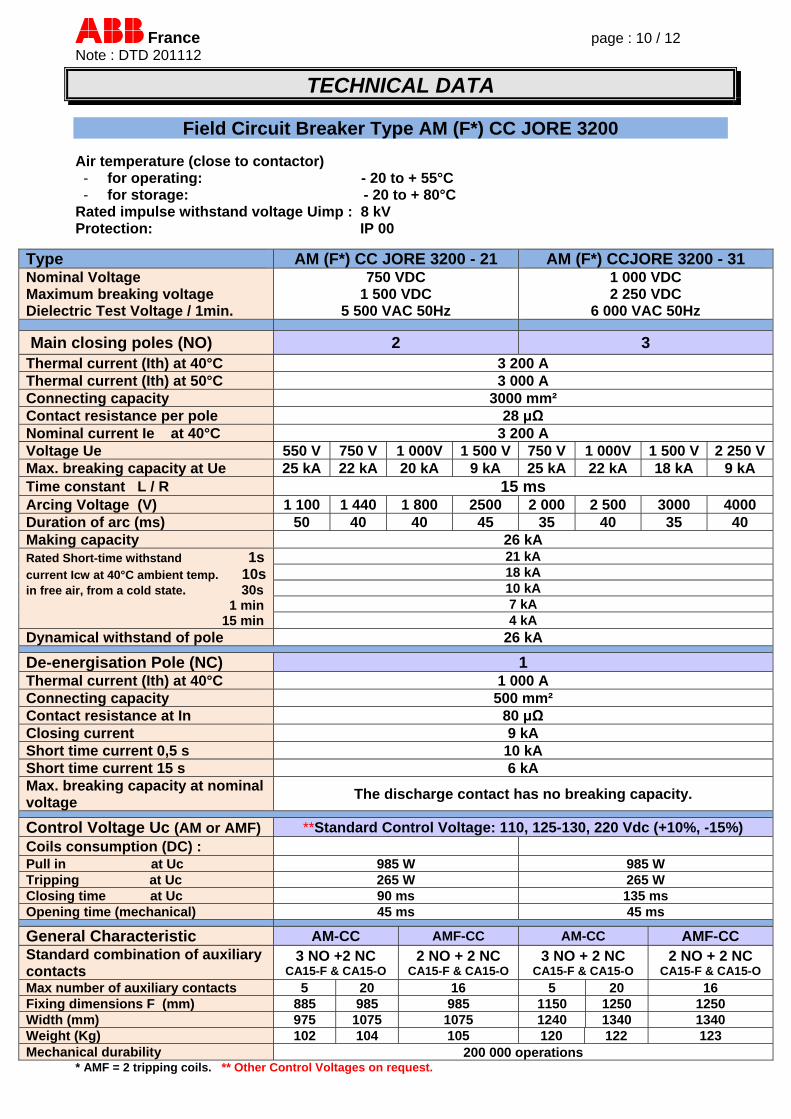
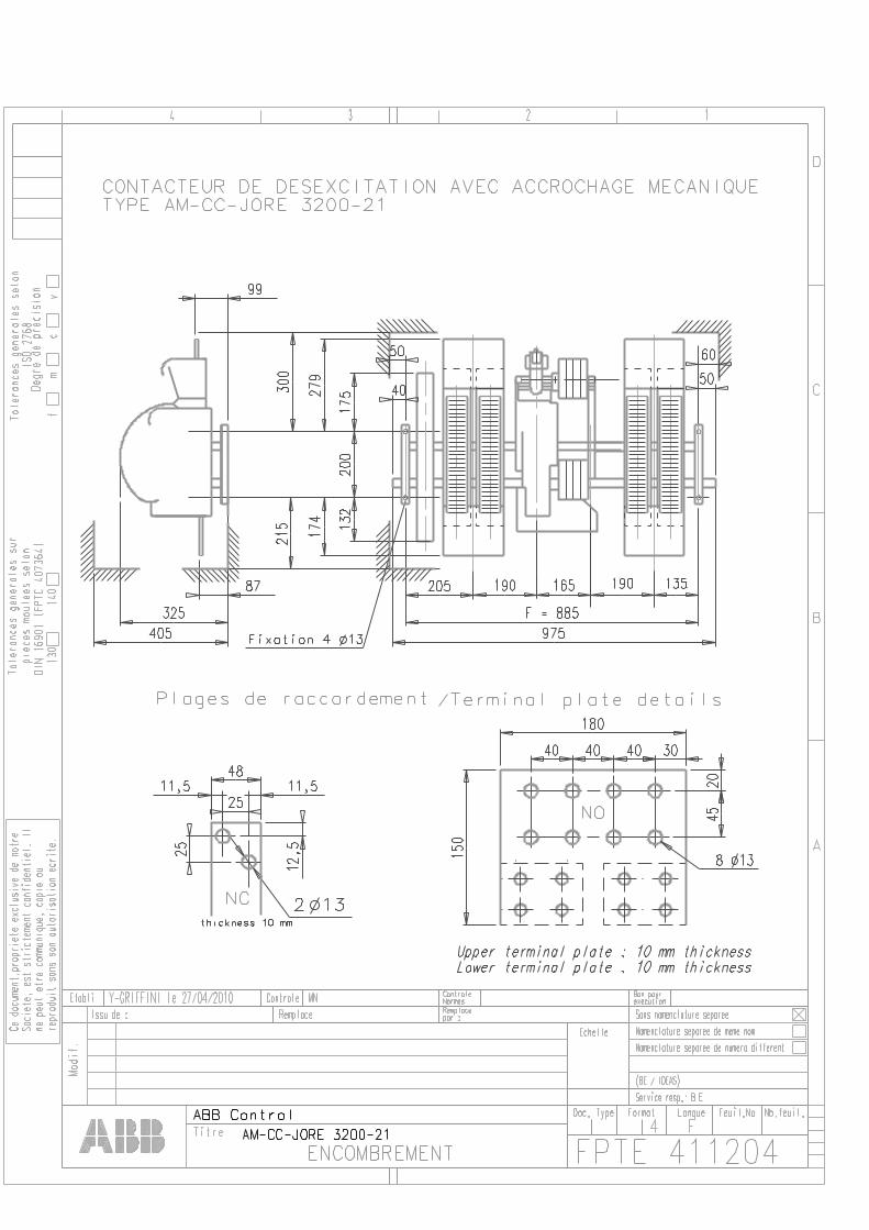
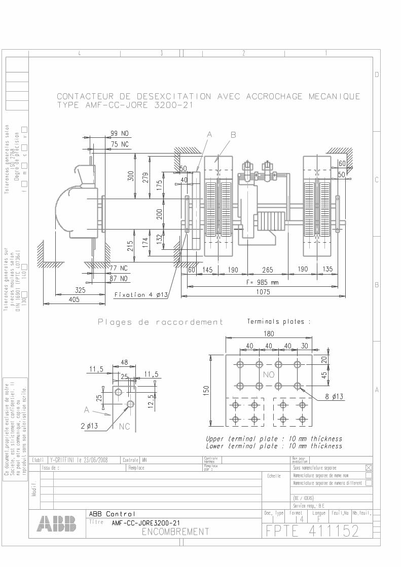
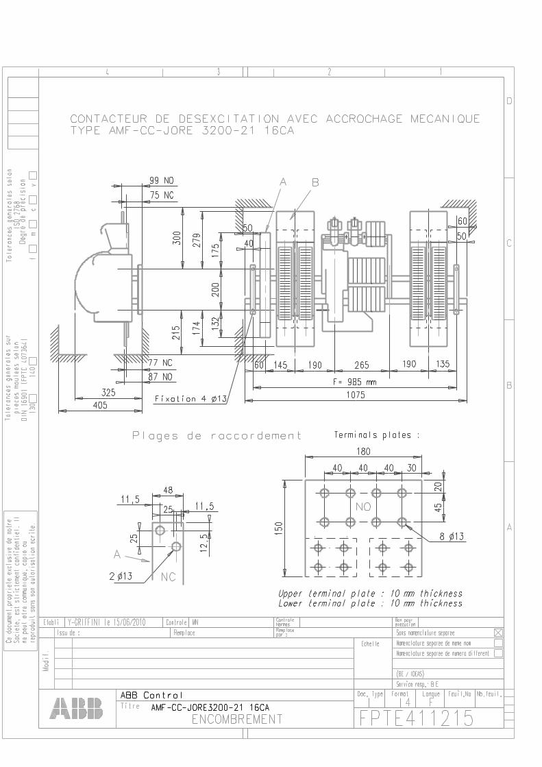
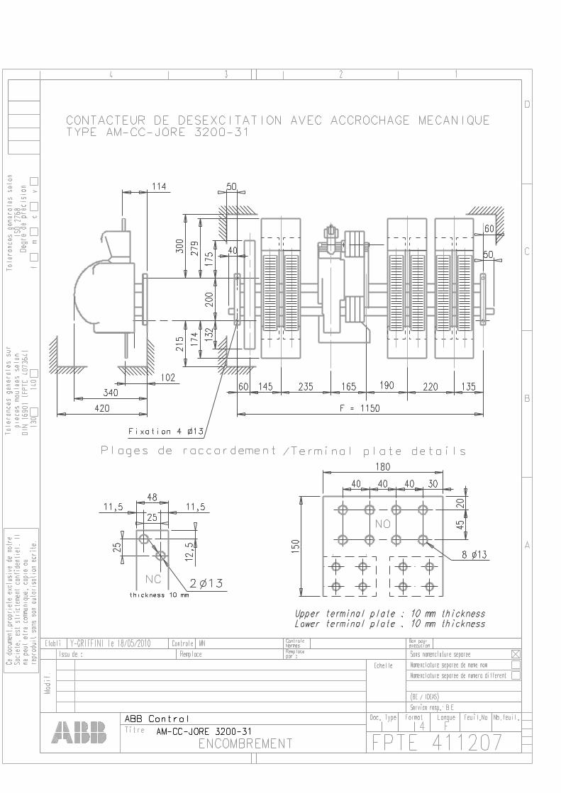
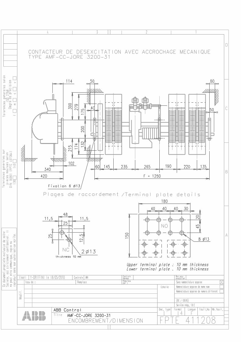
Field Circuit Breaker Type AM (F*) CC JORE 3200 Air temperature (close to contactor) - for operating: - 20 to + 55°C - for storage: - 20 to + 80°C
Rated impulse withstand voltage Uimp : 8 kV Protection: IP 00
Type AM (F*) CC JORE 3200 - 21 AM (F*) CCJORE 3200 - 31 Nominal Voltage Maximum breaking voltage Dielectric Test Voltage / 1min.
750 VDC 1 500 VDC
5 500 VAC 50Hz
1 000 VDC 2 250 VDC
6 000 VAC 50Hz
Main closing poles (NO) 2 3 Thermal current (Ith) at 40°C 3 200 A Thermal current (Ith) at 50°C 3 000 A Connecting capacity 3000 mm² Contact resistance per pole 28 μΩ Nominal current Ie at 40°C 3 200 A Voltage Ue 550 V 750 V 1 000V 1 500 V 750 V 1 000V 1 500 V 2 250 VMax. breaking capacity at Ue 25 kA 22 kA 20 kA 9 kA 25 kA 22 kA 18 kA 9 kA Time constant L / R 15 ms Arcing Voltage (V) 1 100 1 440 1 800 2500 2 000 2 500 3000 4000 Duration of arc (ms) 50 40 40 45 35 40 35 40 Making capacity 26 kA Rated Short-time withstand 1s current Icw at 40°C ambient temp. 10s in free air, from a cold state. 30s 1 min 15 min
21 kA 18 kA 10 kA 7 kA 4 kA
Dynamical withstand of pole 26 kA
De-energisation Pole (NC) 1 Thermal current (Ith) at 40°C 1 000 A Connecting capacity 500 mm² Contact resistance at In 80 μΩ Closing current 9 kA Short time current 0,5 s 10 kA Short time current 15 s 6 kA Max. breaking capacity at nominal voltage
The discharge contact has no breaking capacity.
Control Voltage Uc (AM or AMF) **Standard Control Voltage: 110, 125-130, 220 Vdc (+10%, -15%) Coils consumption (DC) : Pull in at Uc 985 W 985 W Tripping at Uc 265 W 265 W Closing time at Uc 90 ms 135 ms Opening time (mechanical) 45 ms 45 ms
General Characteristic AM-CC AMF-CC AM-CC AMF-CC Standard combination of auxiliary contacts
3 NO +2 NC CA15-F & CA15-O
2 NO + 2 NC CA15-F & CA15-O
3 NO + 2 NC CA15-F & CA15-O
2 NO + 2 NC CA15-F & CA15-O
Max number of auxiliary contacts 5 20 16 5 20 16 Fixing dimensions F (mm) 885 985 985 1150 1250 1250 Width (mm) 975 1075 1075 1240 1340 1340 Weight (Kg) 102 104 105 120 122 123 Mechanical durability 200 000 operations
* AMF = 2 tripping coils. ** Other Control Voltages on request.
France page : 11 / 12 Note : DTD 201112
TECHNICAL DATA
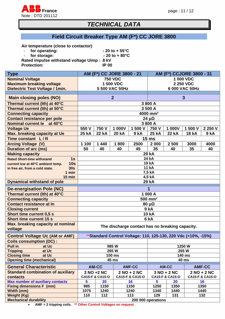
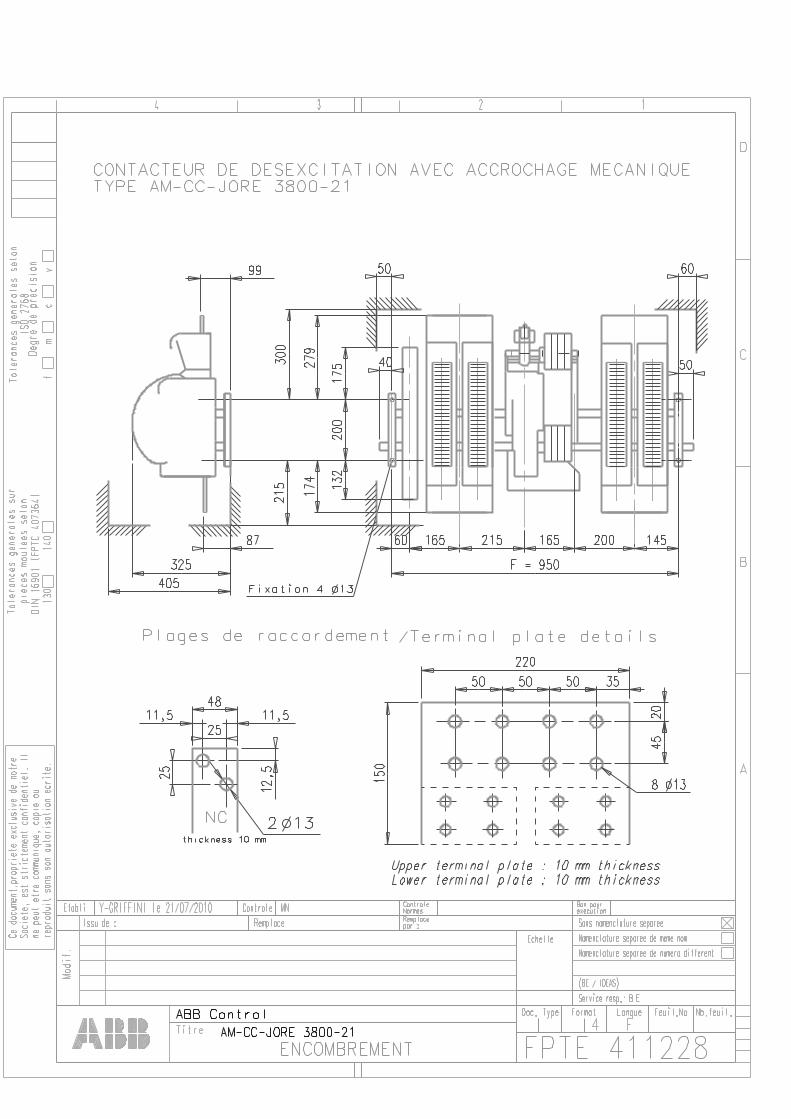
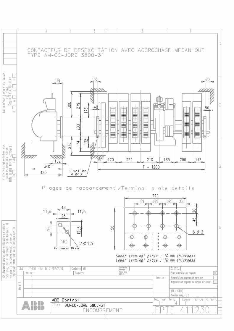
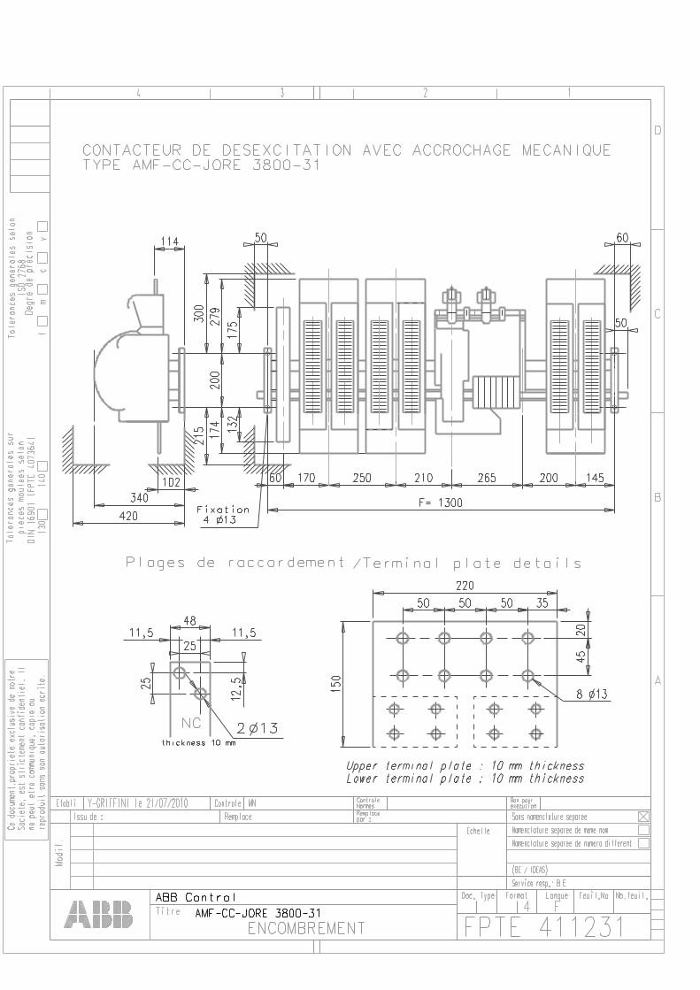
Field Circuit Breaker Type AM (F*) CC JORE 3800 Air temperature (close to contactor) - for operating: - 20 to + 55°C - for storage: - 20 to + 80°C
Rated impulse withstand voltage Uimp : 8 kV Protection: IP 00
Type AM (F*) CC JORE 3800 - 21 AM (F*) CCJORE 3800 - 31 Nominal Voltage Maximum breaking voltage Dielectric Test Voltage / 1min.
750 VDC 1 500 VDC
5 500 VAC 50Hz
1 000 VDC 2 250 VDC
6 000 VAC 50Hz
Main closing poles (NO) 2 3 Thermal current (Ith) at 40°C 3 800 A Thermal current (Ith) at 50°C 3 500 A Connecting capacity 4000 mm² Contact resistance per pole 24 μΩ Nominal current Ie at 40°C 3 800 A Voltage Ue 550 V 750 V 1 000V 1 500 V 750 V 1 000V 1 500 V 2 250 VMax. breaking capacity at Ue 25 kA 22 kA 20 kA 9 kA 25 kA 22 kA 18 kA 9 kA Time constant L / R 15 ms Arcing Voltage (V) 1 100 1 440 1 800 2500 2 000 2 500 3000 4000 Duration of arc (ms) 50 40 40 45 35 40 35 40 Making capacity 29 kA Rated Short-time withstand 1s current Icw at 40°C ambient temp. 10s in free air, from a cold state. 30s 1 min 15 min
24 kA 19 kA 11 kA 7,5 kA 4,5 kA
Dynamical withstand of pole 29 kA
De-energisation Pole (NC) 1 Thermal current (Ith) at 40°C 1 000 A Connecting capacity 500 mm² Contact resistance at In 80 μΩ Closing current 9 kA Short time current 0,5 s 10 kA Short time current 15 s 6 kA Max. breaking capacity at nominal voltage
The discharge contact has no breaking capacity.
Control Voltage Uc (AM or AMF) **Standard Control Voltage: 110, 125-130, 220 Vdc (+10%, -15%) Coils consumption (DC) : Pull in at Uc 985 W 1250 W Tripping at Uc 265 W 265 W Closing time at Uc 100 ms 140 ms Opening time (mechanical) 45 ms 40 ms
General Characteristic AM-CC AMF-CC AM-CC AMF-CC Standard combination of auxiliary contacts
3 NO +2 NC CA15-F & CA15-O
2 NO + 2 NC CA15-F & CA15-O
3 NO + 2 NC CA15-F & CA15-O
2 NO + 2 NC CA15-F & CA15-O
Max number of auxiliary contacts 5 20 16 5 20 16 Fixing dimensions F (mm) 985 1150 1150 1250 1350 1350 Width (mm) 1075 1240 1240 1340 1440 1440 Weight (Kg) 110 112 113 129 131 132 Mechanical durability 200 000 operations
AMF = 2 tripping coils. ** Other Control Voltages on request.
France page : 12 / 12 Note : DTD 201112
TECHNICAL DATA
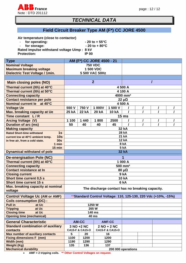
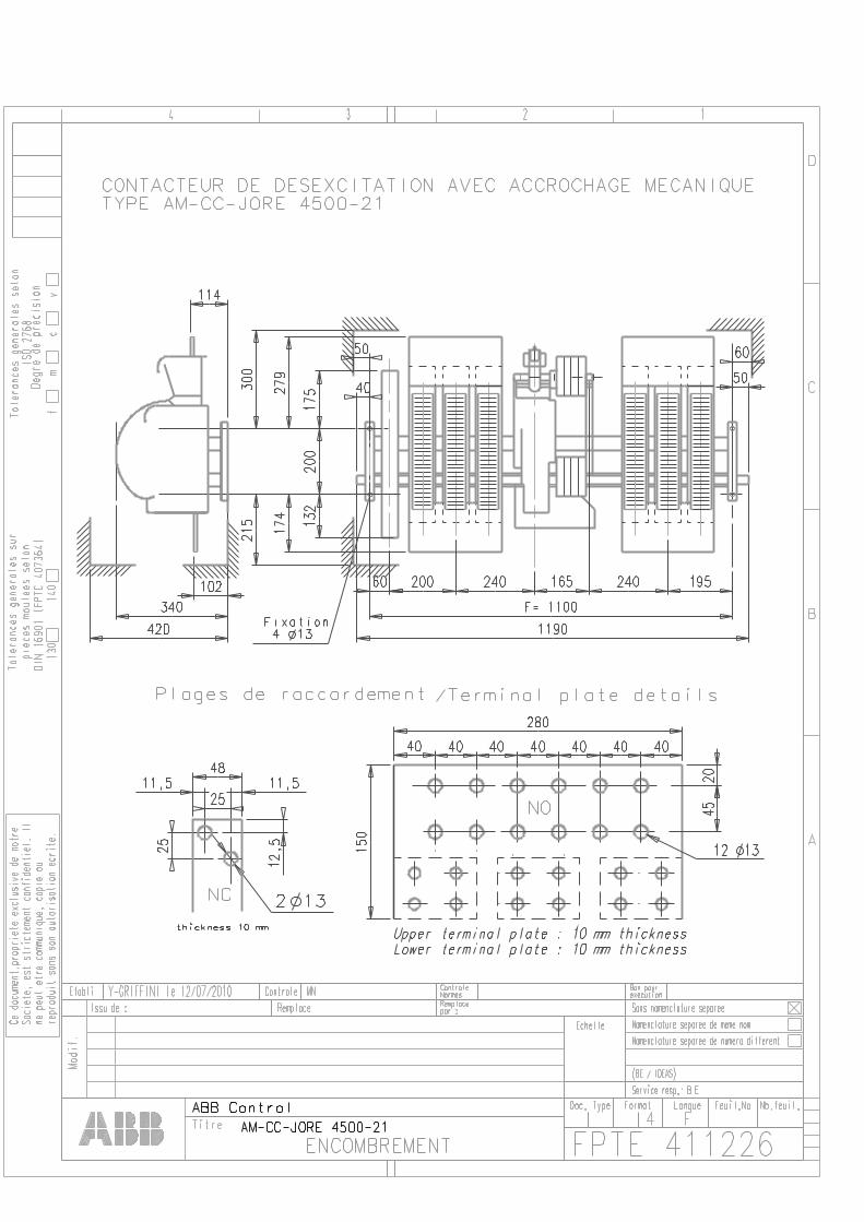
Field Circuit Breaker Type AM (F*) CC JORE 4500 Air temperature (close to contactor) - for operating: - 20 to + 55°C - for storage: - 20 to + 80°C
Rated impulse withstand voltage Uimp : 8 kV Protection: IP 00
Type AM (F*) CC JORE 4500 - 21 Nominal Voltage Maximum breaking voltage Dielectric Test Voltage / 1min.
750 VDC 1 500 VDC
5 500 VAC 50Hz
Main closing poles (NO) 2 /
Thermal current (Ith) at 40°C 4 500 A Thermal current (Ith) at 50°C 4 100 A Connecting capacity 4000 mm² Contact resistance per pole 22 μΩ Nominal current Ie at 40°C 4 500 A Voltage Ue 550 V 750 V 1 000V 1 500 V / / / / Max. breaking capacity at Ue 25 kA 22 kA 20 kA 10 kA / / / / Time constant L / R 15 ms Arcing Voltage (V) 1 100 1 440 1 800 2500 / / / / Duration of arc (ms) 50 40 40 45 / / / / Making capacity 32 kA Rated Short-time withstand 1s current Icw at 40°C ambient temp. 10s in free air, from a cold state. 30s 1 min 15 min
28 kA 21 kA 12 kA 8 kA 5 kA
Dynamical withstand of pole 32 kA
De-energisation Pole (NC) 1 Thermal current (Ith) at 40°C 1 000 A Connecting capacity 500 mm² Contact resistance at In 80 μΩ Closing current 9 kA Short time current 0,5 s 10 kA Short time current 15 s 6 kA Max. breaking capacity at nominal voltage
The discharge contact has no breaking capacity.
Control Voltage Uc (AM or AMF) **Standard Control Voltage: 110, 125-130, 220 Vdc (+10%, -15%) Coils consumption (DC) : Pull in at Uc 1250 W Tripping at Uc 265 W Closing time at Uc 140 ms Opening time (mechanical) 40 ms
General Characteristic AM-CC AMF-CC Standard combination of auxiliary contacts
3 NO +2 NC CA15-F & CA15-O
2 NO + 2 NC CA15-F & CA15-O
Max number of auxiliary contacts 5 20 16 Fixing dimensions F (mm) 1100 1200 1200 Width (mm) 1190 1290 1290 Weight (Kg) 135 136 137 Mechanical durability 200 000 operations
AMF = 2 tripping coils. ** Other Control Voltages on request.
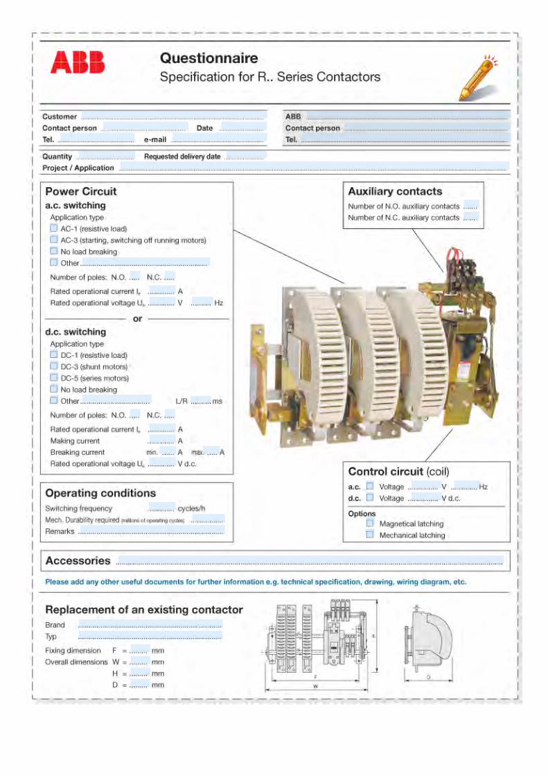
Questionnaire
Questionnaire
4
x
x
x
x
x
x
Specific Spare Parts
Pièces de rechange spécifiques
Contents / Sommaire
- Main Contacts Sets / Jeux de contacts principaux
- Arcing Horns / Cornes de soufflage
- Equipotential connection / Connexion équipotentielle
- Arc Chutes / Cages de soufflage
- Auxiliary Contacts / Contacts auxiliaires
- Mouting Kit for CA15.. Auxiliary contacts / Kit de montage pour les contacts auxiliaires CA15..
- Surge Suppressors Blocks / Blocs limiteurs de surtensions
- Operating Coils / Bobines
5
Spare Parts Pièces de rechange Ordering Details Références de commande
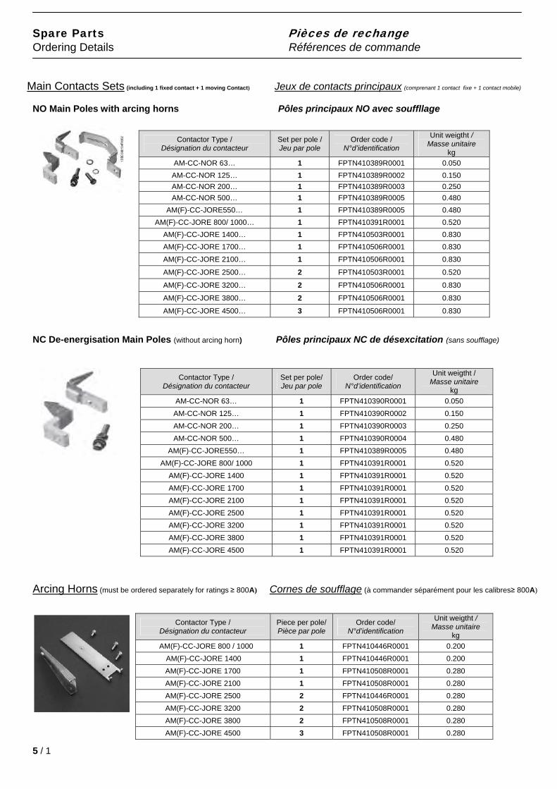
Main Contacts Sets (including 1 fixed contact + 1 moving Contact) Jeux de contacts principaux (comprenant 1 contact fixe + 1 contact mobile)
NO Main Poles with arcing horns Pôles principaux NO avec souffllage
Contactor Type / Désignation du contacteur
Set per pole / Jeu par pole
Order code / N°d’identification
Unit weigtht / Masse unitaire
kg
AM-CC-NOR 63… 1 FPTN410389R0001 0.050
AM-CC-NOR 125… 1 FPTN410389R0002 0.150
AM-CC-NOR 200… 1 FPTN410389R0003 0.250
AM-CC-NOR 500… 1 FPTN410389R0005 0.480
AM(F)-CC-JORE550… 1 FPTN410389R0005 0.480
AM(F)-CC-JORE 800/ 1000… 1 FPTN410391R0001 0.520
AM(F)-CC-JORE 1400… 1 FPTN410503R0001 0.830
AM(F)-CC-JORE 1700… 1 FPTN410506R0001 0.830
AM(F)-CC-JORE 2100… 1 FPTN410506R0001 0.830
AM(F)-CC-JORE 2500… 2 FPTN410503R0001 0.520
AM(F)-CC-JORE 3200… 2 FPTN410506R0001 0.830
AM(F)-CC-JORE 3800… 2 FPTN410506R0001 0.830
AM(F)-CC-JORE 4500… 3 FPTN410506R0001 0.830
NC De-energisation Main Poles (without arcing horn) Pôles principaux NC de désexcitation (sans soufflage)
Contactor Type / Désignation du contacteur
Set per pole/ Jeu par pole
Order code/ N°d’identification
Unit weigtht / Masse unitaire
kg
AM-CC-NOR 63… 1 FPTN410390R0001 0.050
AM-CC-NOR 125… 1 FPTN410390R0002 0.150
AM-CC-NOR 200… 1 FPTN410390R0003 0.250
AM-CC-NOR 500… 1 FPTN410390R0004 0.480
AM(F)-CC-JORE550… 1 FPTN410389R0005 0.480
AM(F)-CC-JORE 800/ 1000 1 FPTN410391R0001 0.520
AM(F)-CC-JORE 1400 1 FPTN410391R0001 0.520 AM(F)-CC-JORE 1700 1 FPTN410391R0001 0.520 AM(F)-CC-JORE 2100 1 FPTN410391R0001 0.520 AM(F)-CC-JORE 2500 1 FPTN410391R0001 0.520 AM(F)-CC-JORE 3200 1 FPTN410391R0001 0.520 AM(F)-CC-JORE 3800 1 FPTN410391R0001 0.520 AM(F)-CC-JORE 4500 1 FPTN410391R0001 0.520
Arcing Horns (must be ordered separately for ratings ≥ 800A) Cornes de soufflage (à commander séparément pour les calibres≥ 800A)
Contactor Type / Désignation du contacteur
Piece per pole/ Pièce par pole
Order code/ N°d’identification
Unit weigtht / Masse unitaire
kg
AM(F)-CC-JORE 800 / 1000 1 FPTN410446R0001 0.200
AM(F)-CC-JORE 1400 1 FPTN410446R0001 0.200 AM(F)-CC-JORE 1700 1 FPTN410508R0001 0.280 AM(F)-CC-JORE 2100 1 FPTN410508R0001 0.280 AM(F)-CC-JORE 2500 2 FPTN410446R0001 0.280 AM(F)-CC-JORE 3200 2 FPTN410508R0001 0.280 AM(F)-CC-JORE 3800 2 FPTN410508R0001 0.280 AM(F)-CC-JORE 4500 3 FPTN410508R0001 0.280
5 / 1
Spare Parts Pièces de rechange Ordering Details Références de commande
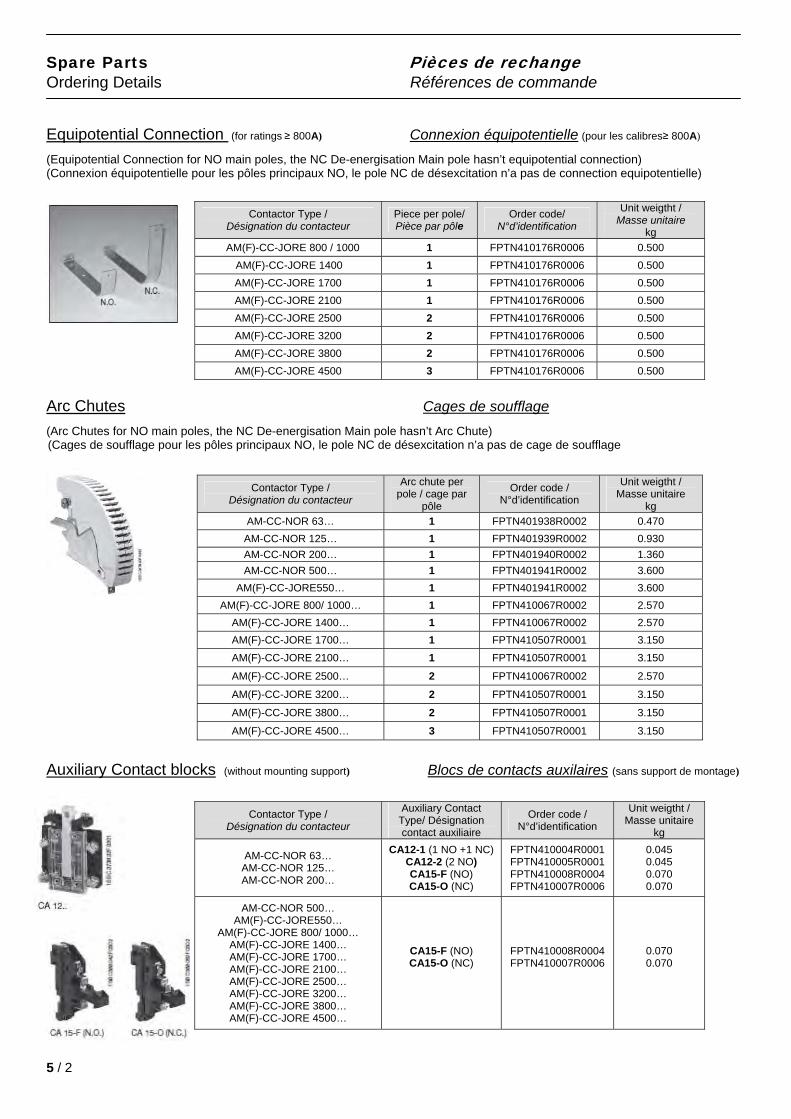
Equipotential Connection (for ratings ≥ 800A) Connexion équipotentielle (pour les calibres≥ 800A)
(Equipotential Connection for NO main poles, the NC De-energisation Main pole hasn’t equipotential connection) (Connexion équipotentielle pour les pôles principaux NO, le pole NC de désexcitation n’a pas de connection equipotentielle)
Contactor Type / Désignation du contacteur
Piece per pole/ Pièce par pôle
Order code/ N°d’identification
Unit weigtht / Masse unitaire
kg
AM(F)-CC-JORE 800 / 1000 1 FPTN410176R0006 0.500
AM(F)-CC-JORE 1400 1 FPTN410176R0006 0.500 AM(F)-CC-JORE 1700 1 FPTN410176R0006 0.500 AM(F)-CC-JORE 2100 1 FPTN410176R0006 0.500 AM(F)-CC-JORE 2500 2 FPTN410176R0006 0.500 AM(F)-CC-JORE 3200 2 FPTN410176R0006 0.500 AM(F)-CC-JORE 3800 2 FPTN410176R0006 0.500 AM(F)-CC-JORE 4500 3 FPTN410176R0006 0.500
Arc Chutes Cages de soufflage
(Arc Chutes for NO main poles, the NC De-energisation Main pole hasn’t Arc Chute) (Cages de soufflage pour les pôles principaux NO, le pole NC de désexcitation n’a pas de cage de soufflage
Contactor Type / Désignation du contacteur
Arc chute per pole / cage par
pôle
Order code / N°d’identification
Unit weigtht / Masse unitaire
kg
AM-CC-NOR 63… 1 FPTN401938R0002 0.470
AM-CC-NOR 125… 1 FPTN401939R0002 0.930
AM-CC-NOR 200… 1 FPTN401940R0002 1.360
AM-CC-NOR 500… 1 FPTN401941R0002 3.600
AM(F)-CC-JORE550… 1 FPTN401941R0002 3.600
AM(F)-CC-JORE 800/ 1000… 1 FPTN410067R0002 2.570
AM(F)-CC-JORE 1400… 1 FPTN410067R0002 2.570
AM(F)-CC-JORE 1700… 1 FPTN410507R0001 3.150
AM(F)-CC-JORE 2100… 1 FPTN410507R0001 3.150
AM(F)-CC-JORE 2500… 2 FPTN410067R0002 2.570
AM(F)-CC-JORE 3200… 2 FPTN410507R0001 3.150
AM(F)-CC-JORE 3800… 2 FPTN410507R0001 3.150
AM(F)-CC-JORE 4500… 3 FPTN410507R0001 3.150
Auxiliary Contact blocks (without mounting support) Blocs de contacts auxilaires (sans support de montage)
Contactor Type / Désignation du contacteur
Auxiliary Contact Type/ Désignation contact auxiliaire
Order code / N°d’identification
Unit weigtht / Masse unitaire
kg
AM-CC-NOR 63… AM-CC-NOR 125… AM-CC-NOR 200…
CA12-1 (1 NO +1 NC) CA12-2 (2 NO) CA15-F (NO) CA15-O (NC)
FPTN410004R0001 FPTN410005R0001 FPTN410008R0004 FPTN410007R0006
0.045 0.045 0.070 0.070
AM-CC-NOR 500… AM(F)-CC-JORE550…
AM(F)-CC-JORE 800/ 1000… AM(F)-CC-JORE 1400… AM(F)-CC-JORE 1700… AM(F)-CC-JORE 2100… AM(F)-CC-JORE 2500… AM(F)-CC-JORE 3200… AM(F)-CC-JORE 3800… AM(F)-CC-JORE 4500…
CA15-F (NO) CA15-O (NC)
FPTN410008R0004 FPTN410007R0006
0.070 0.070
5 / 2
Spare Parts Pièces de rechange
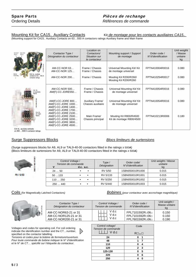
Ordering Details Références de commande Mounting Kit for CA15.. Auxiliary Contacts Kit de montage pour les contacts auxiliaires CA15..
(Mounting support for CA15.. Auxiliary Contacts on 63…550 A contactors ratings Auxiliary frame and Main frame
Contactor Type / Désignation du contacteur
Location on Contactors/ Situation sur le contacteur
Mounting support / Support de montage
Order code / N°d’identification
Unit weigtht / Masse unitaire
kg
AM-CC-NOR 63… AM-CC-NOR 125…
AM-CC-NOR 200…
Frame / Chassis Frame / Chassis Frame / Chassis
Universal Mounting Kit/ Kit de montage universel Mouting Kit R200/R260/ Mouting Kit R200/R260
FPTN410004R0016
FPTN410254R0017
0.080
0.080
AM-CC-NOR 500…
AM(F)-CC-JORE550…
AM(F)-CC-JORE 800… AM(F)-CC-JORE 1000… AM(F)-CC-JORE 1400… AM(F)-CC-JORE 1700… AM(F)-CC-JORE 2100… AM(F)-CC-JORE 2500… AM(F)-CC-JORE 3200… AM(F)-CC-JORE 3800… AM(F)-CC-JORE 4500…
Frame / Chassis Frame / Chassis
Auxiliary Frame/ Chassis auxiliaire
Main Frame/ Chassis principal
Universal Mounting Kit/ Kit
de montage universel
Universal Mounting Kit/ Kit
de montage universel
Mouting Kit R800/R4500 Kit de montage R800/4500
FPTN410054R0016
FPTN410054R0016
FPTN410213R0006
0.080
0.080
0.180
Surge Suppressors Blocks Blocs limiteurs de surtensions
(Surge suppressors blocks for A9, AL9 or TAL9-40-00 contactors fitted in the ratings ≥ 500A) (Blocs limiteurs de surtensions for A9, AL9 or TAL9-40-00 contactors fitted in the ratings ≥ 500A)
Control Voltage / Tension de commande
V d.c. a.c.
Type / Désignation
Order code/ N°d’identification
Unit weigtht / Masse unitaire
kg
24 … 50 • • RV 5/50 1SBN050010R1000 0.015
50 …133 • • RV 5/133 1SBN050010R1001 0.015 110 … 250 • • RV 5/250 1SBN050010R1002 0.015 250 … 440 • • RV 5/440 1SBN050010R1003 0.015
Coils (for Magnetically Latched Contactors) Bobines (pour contacteur avec accrochage magnétique)
Contactor Type / Désignation du contacteur
Control Voltage / Tension de commande
Order code / N°d’identification
Unit weigtht / Masse unitaire
kg
AM-CC-NOR63-21 or 31 AM-CC-NOR125-21 or 31 AM-CC-NOR200-21 or 31
V d.c V d.c V d.c
FPL7101592R06 FPL7101592R06 FPL7601592R06
0.150 0.150 0.190
Voltages and codes for operating coil. For coil ordering indicate the identification number and the CT…number, specified on the contactor labelling. Tensions et codes pour la bobine de fermeture/ouverture.
Control voltage/ Tension de commande V d.c
Code
R.. 24 0 1 48 1 7
110 0 4 120 2 3
125-130 0 5 220 0 6 250 4 0
Pour toute commande de bobine indiquer le N° d’identification et le N° de CT… spécifié sur l’étiquette du contacteur.
5 / 3
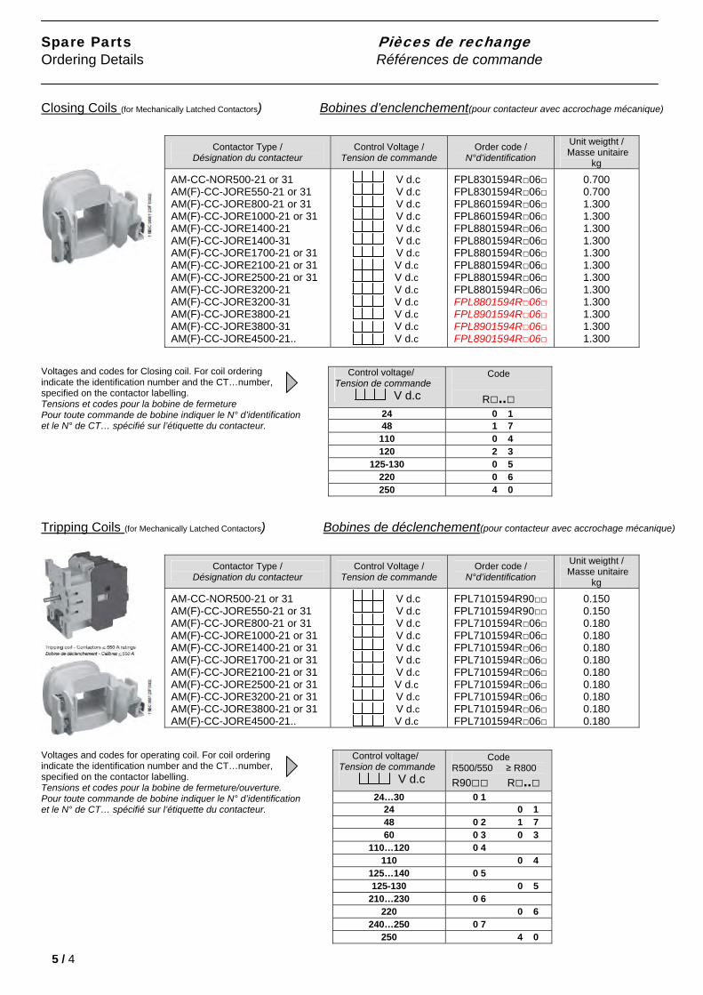
Spare Parts Pièces de rechange Ordering Details Références de commande Closing Coils (for Mechanically Latched Contactors) Bobines d’enclenchement(pour contacteur avec accrochage mécanique)
Contactor Type / Désignation du contacteur
Control Voltage / Tension de commande
Order code / N°d’identification
Unit weigtht / Masse unitaire
kg
AM-CC-NOR500-21 or 31 AM(F)-CC-JORE550-21 or 31 AM(F)-CC-JORE800-21 or 31 AM(F)-CC-JORE1000-21 or 31 AM(F)-CC-JORE1400-21 AM(F)-CC-JORE1400-31 AM(F)-CC-JORE1700-21 or 31 AM(F)-CC-JORE2100-21 or 31 AM(F)-CC-JORE2500-21 or 31 AM(F)-CC-JORE3200-21 AM(F)-CC-JORE3200-31 AM(F)-CC-JORE3800-21 AM(F)-CC-JORE3800-31 AM(F)-CC-JORE4500-21..
V d.c V d.c V d.c V d.c V d.c V d.c V d.c V d.c V d.c V d.c V d.c V d.c V d.c V d.c
FPL8301594R06 FPL8301594R06 FPL8601594R06 FPL8601594R06 FPL8801594R06 FPL8801594R06 FPL8801594R06 FPL8801594R06 FPL8801594R06 FPL8801594R06 FPL8801594R06 FPL8901594R06 FPL8901594R06 FPL8901594R06
0.700 0.700 1.300 1.300 1.300 1.300 1.300 1.300 1.300 1.300 1.300 1.300 1.300 1.300
Voltages and codes for Closing coil. For coil ordering indicate the identification number and the CT…number, specified on the contactor labelling. Tensions et codes pour la bobine de fermeture
Control voltage/
Pour toute commande de bobine indiquer le N° d’identification et le N° de CT… spécifié sur l’étiquette du contacteur.
Tripping Coils (for Mechanically Latched Contactors) Bobines de déclenchement(pour contacteur avec accrochage mécanique)
Voltages and codes for operating coil. For coil ordering indicate the identification number and the CT…number, specified on the contactor labelling. Tensions et codes pour la bobine de fermeture/ouverture. Pour toute commande de bobine indiquer le N° d’identification et le N° de CT… spécifié sur l’étiquette du contacteur.
5 / 4
Tension de commande V d.c
Code
R.. 24 0 1 48 1 7
110 0 4 120 2 3
125-130 0 5 220 0 6 250 4 0
Contactor Type / Désignation du contacteur
Control Voltage / Tension de commande
Order code / N°d’identification
Unit weigtht / Masse unitaire
kg
AM-CC-NOR500-21 or 31 AM(F)-CC-JORE550-21 or 31 AM(F)-CC-JORE800-21 or 31 AM(F)-CC-JORE1000-21 or 31 AM(F)-CC-JORE1400-21 or 31 AM(F)-CC-JORE1700-21 or 31 AM(F)-CC-JORE2100-21 or 31 AM(F)-CC-JORE2500-21 or 31 AM(F)-CC-JORE3200-21 or 31 AM(F)-CC-JORE3800-21 or 31 AM(F)-CC-JORE4500-21..
V d.c V d.c V d.c V d.c
V d.c V d.c V d.c V d.c V d.c V d.c V d.c
FPL7101594R90 FPL7101594R90 FPL7101594R06 FPL7101594R06 FPL7101594R06 FPL7101594R06 FPL7101594R06 FPL7101594R06 FPL7101594R06 FPL7101594R06 FPL7101594R06
0.150 0.150 0.180 0.180 0.180 0.180 0.180 0.180 0.180 0.180 0.180
Control voltage/ Tension de commande V d.c
Code R500/550 ≥ R800
R90 R.. 24…30 0 1
24 0 1 48 0 2 1 7 60 0 3 0 3
110…120 0 4 110 0 4
125…140 0 5 125-130 0 5
210…230 0 6 220 0 6
240…250 0 7 250 4 0
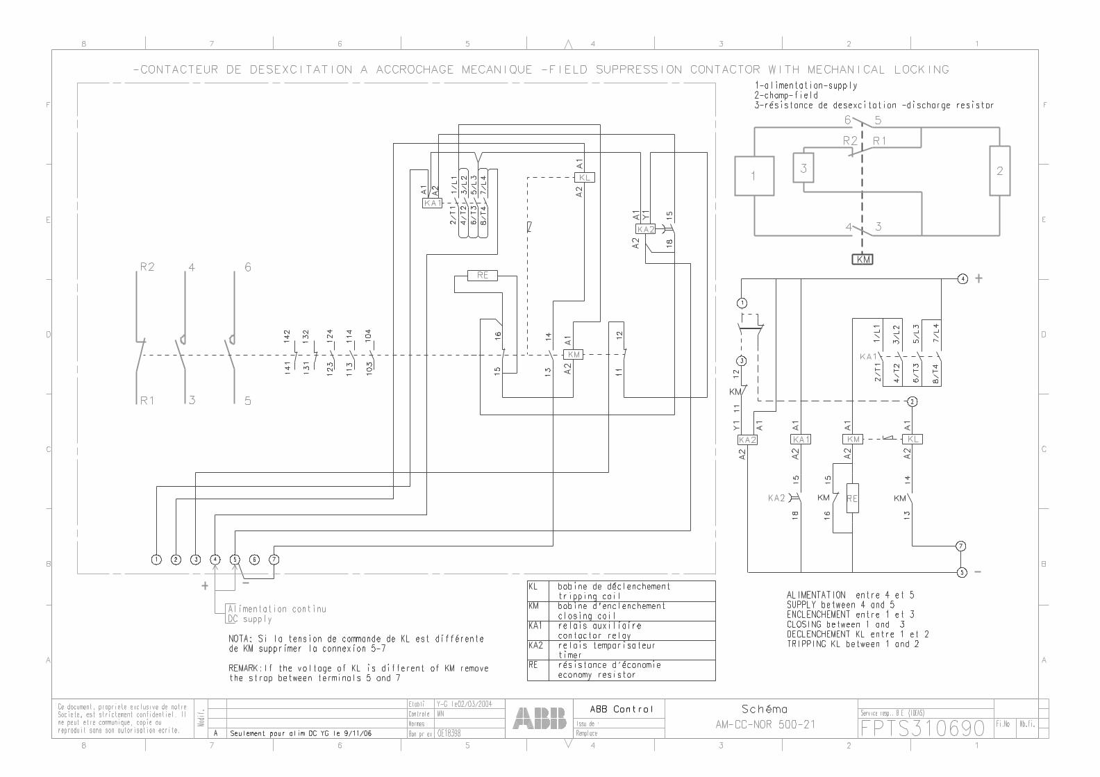
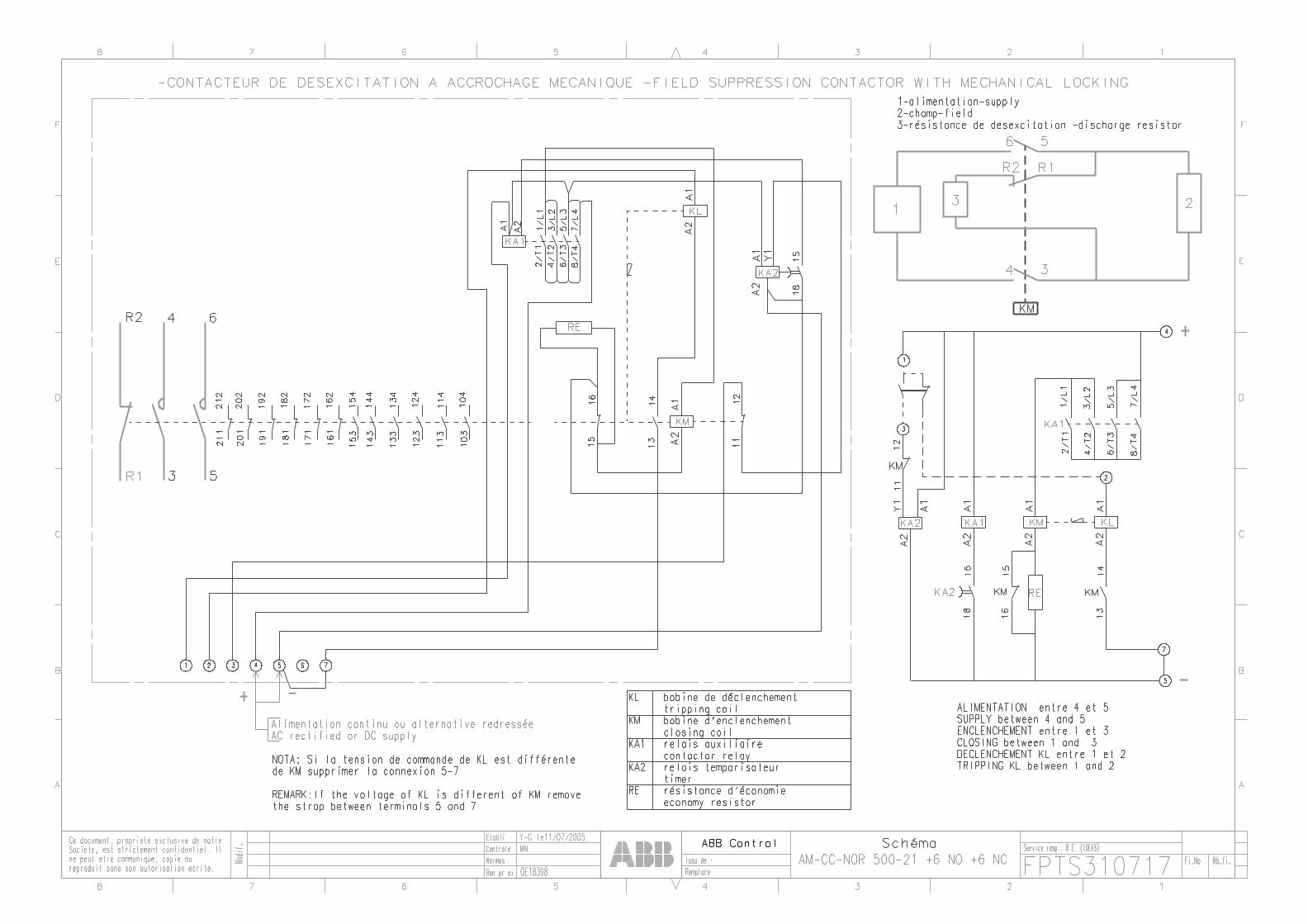
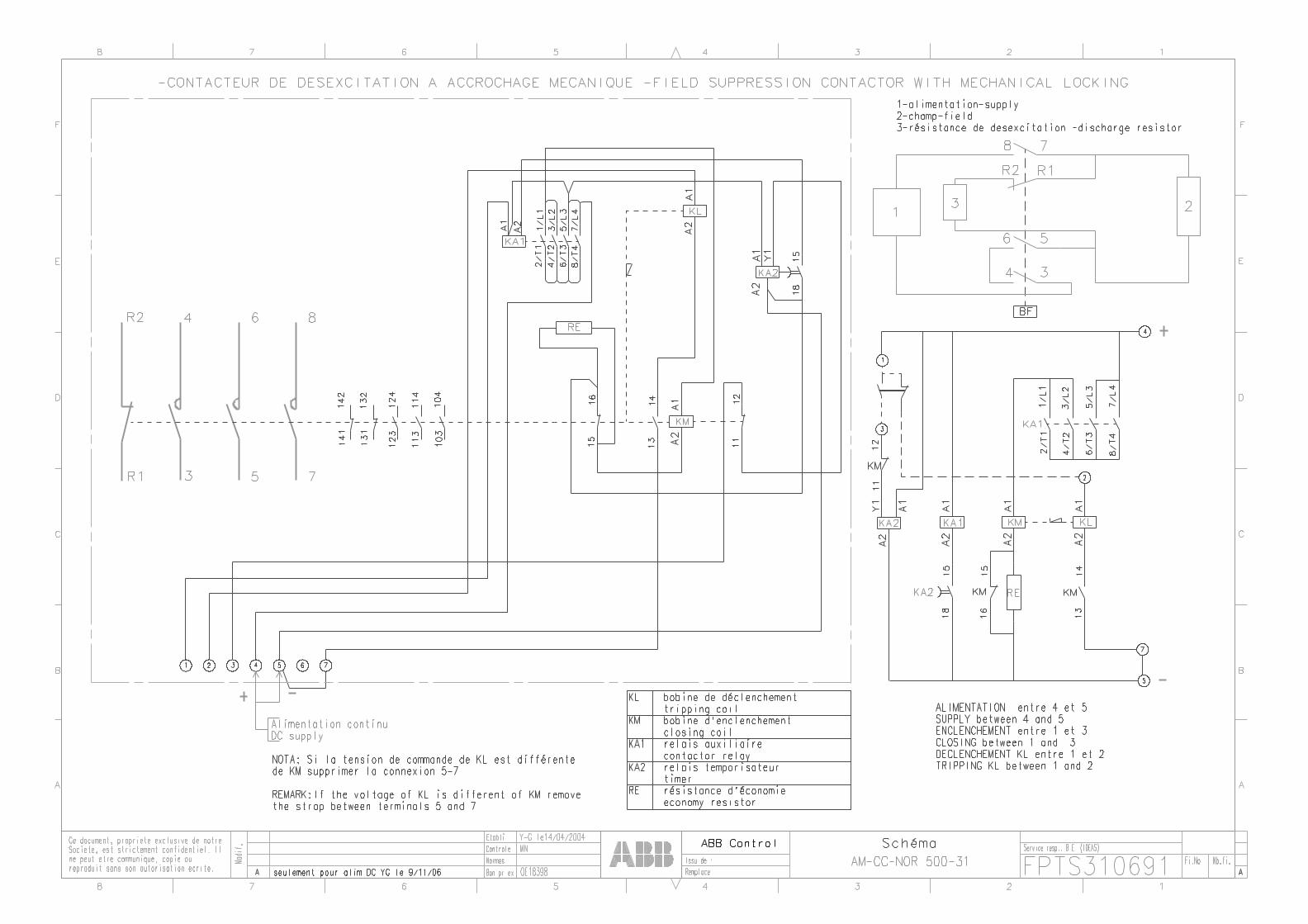
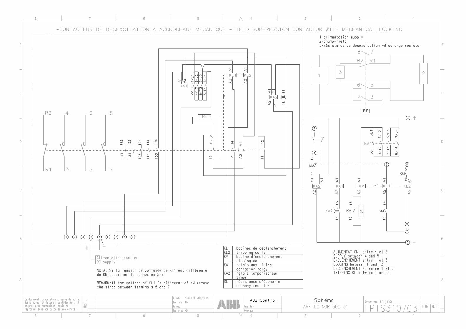
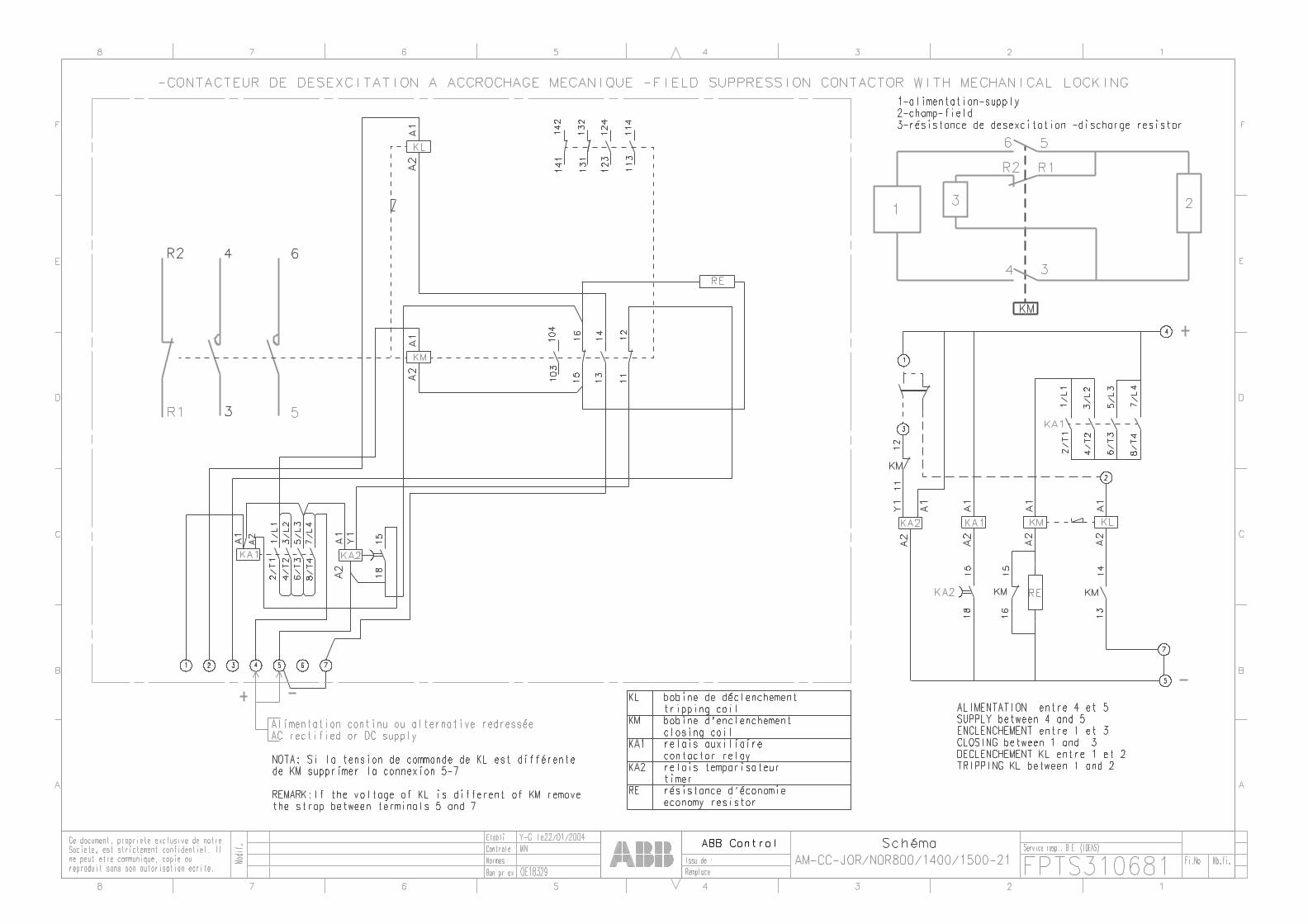
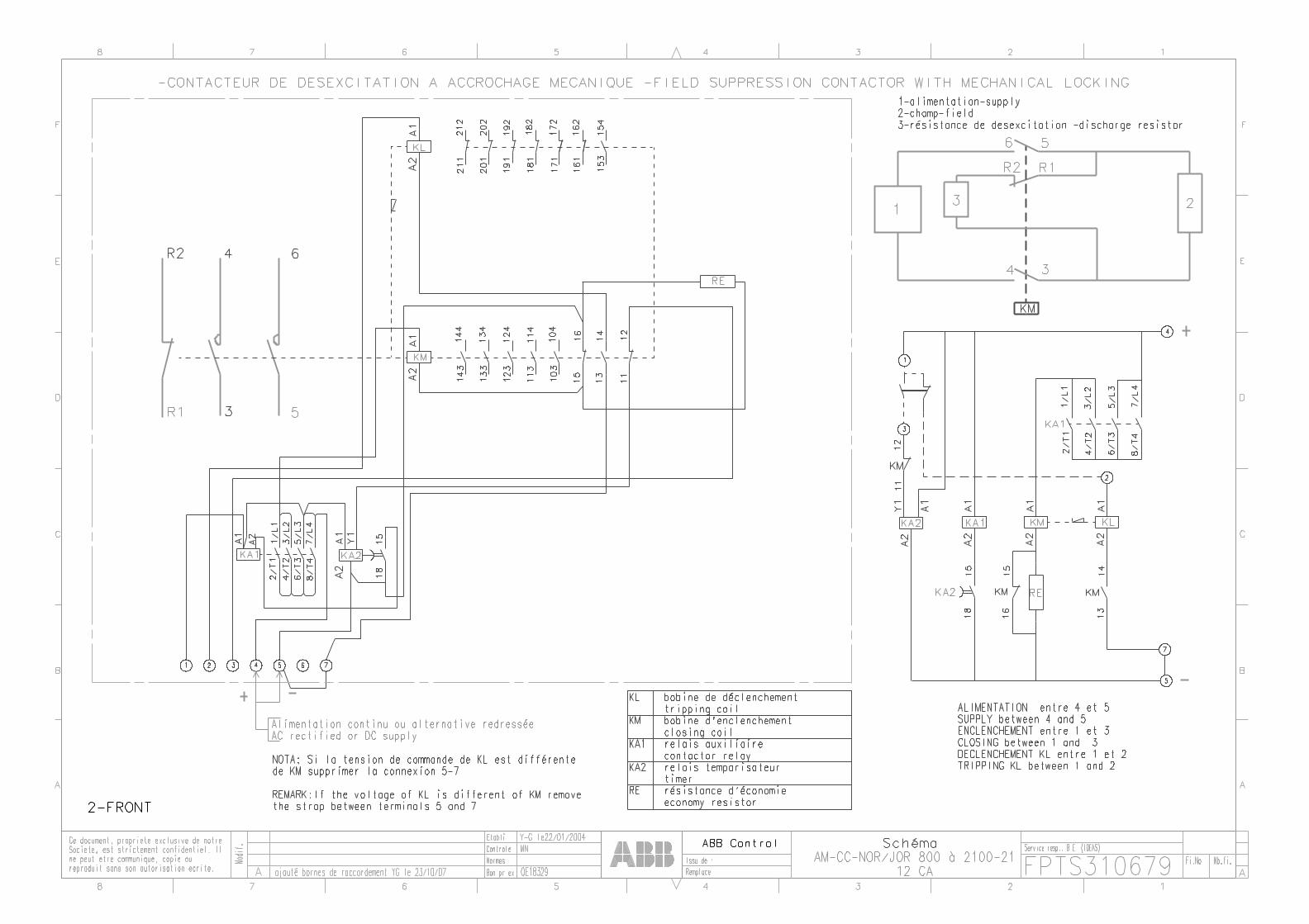
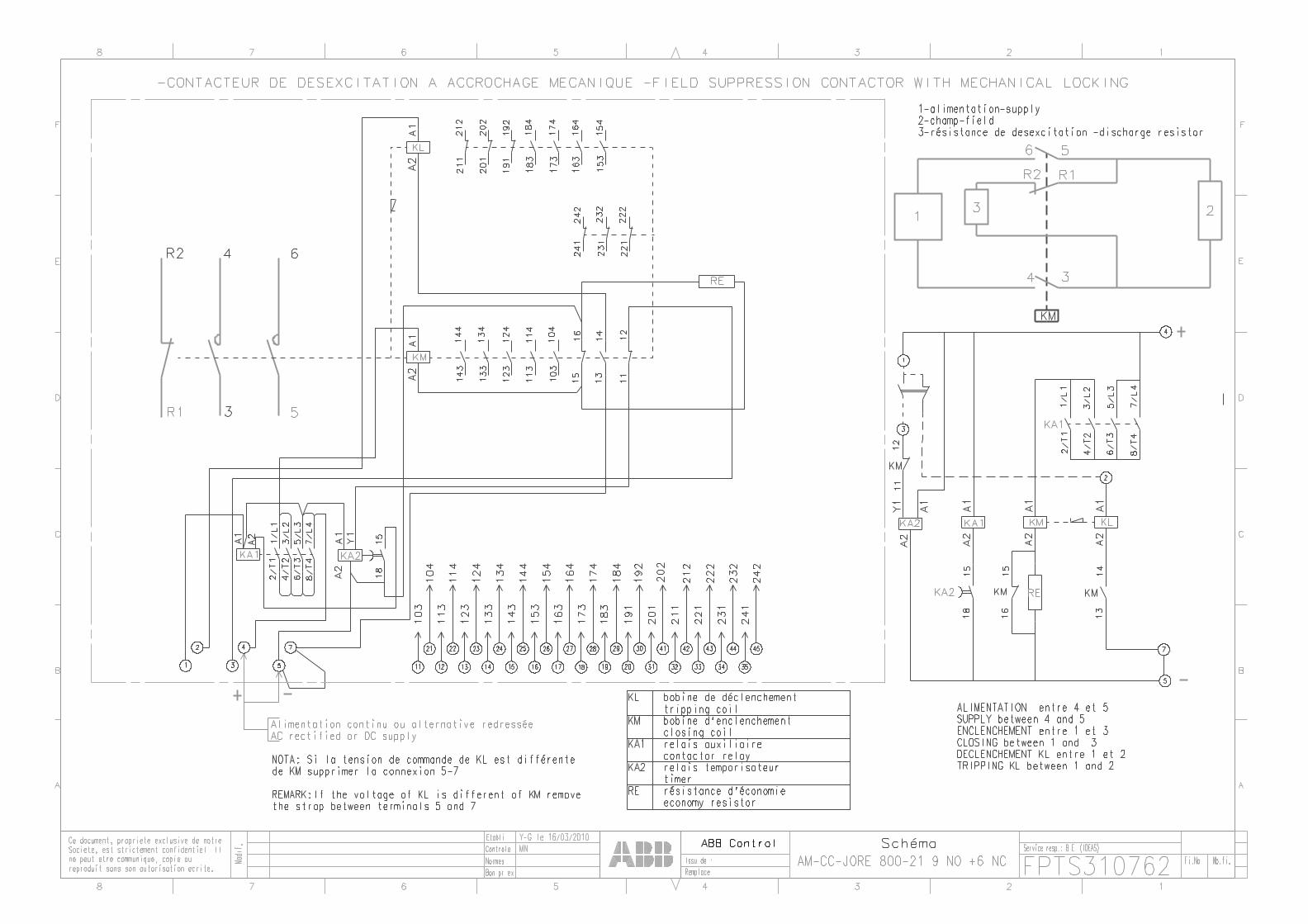
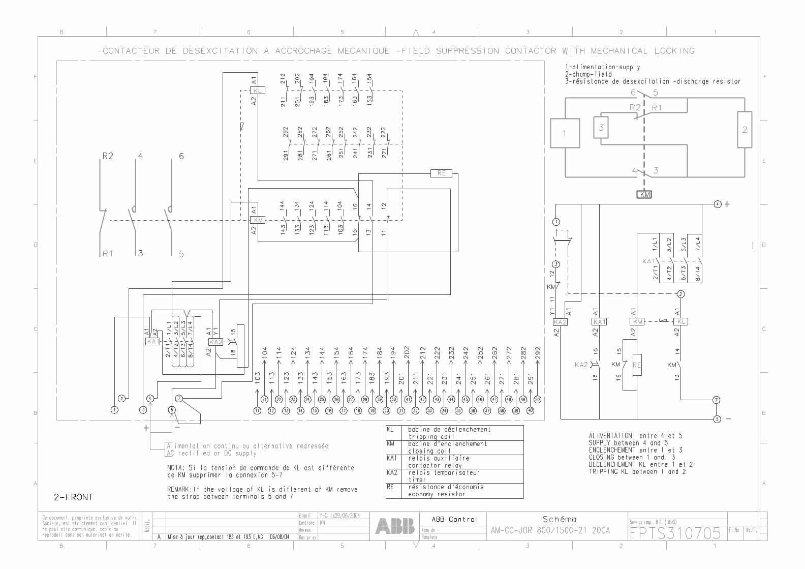
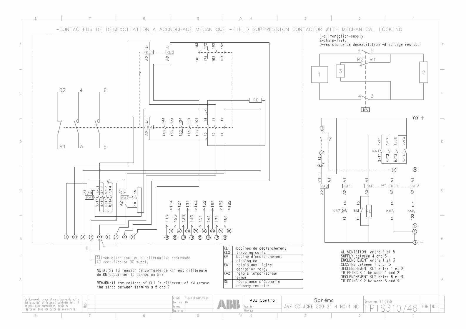
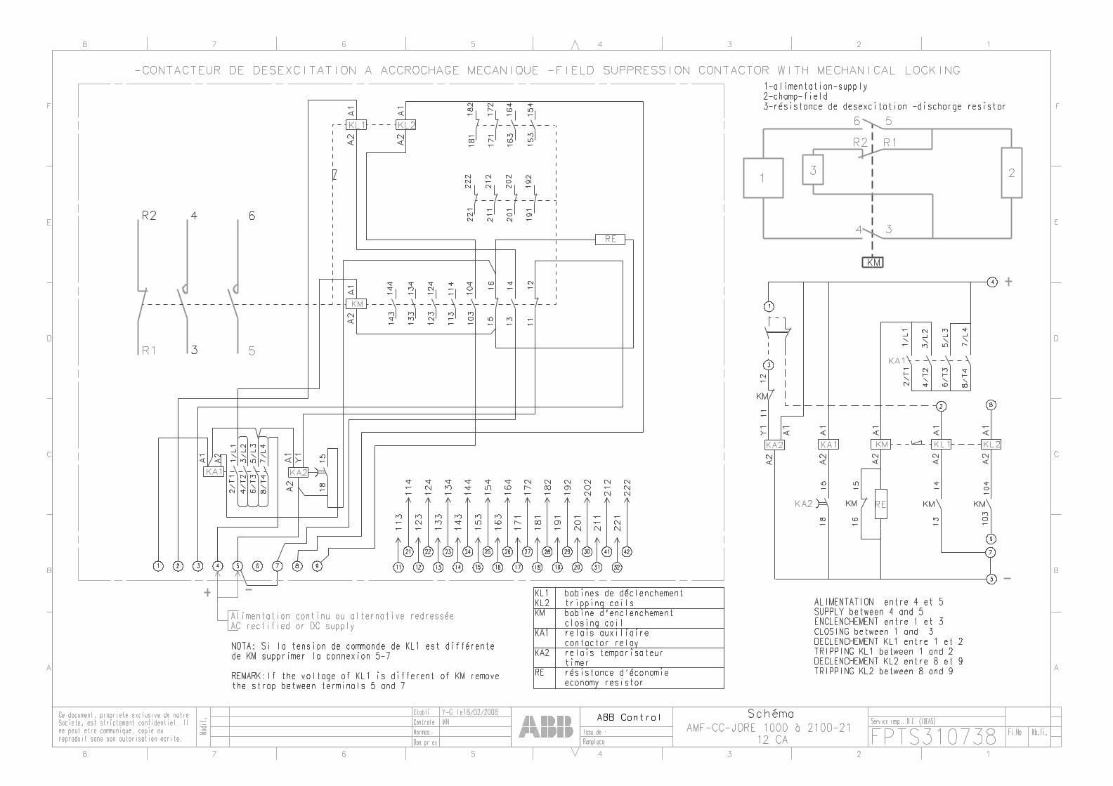
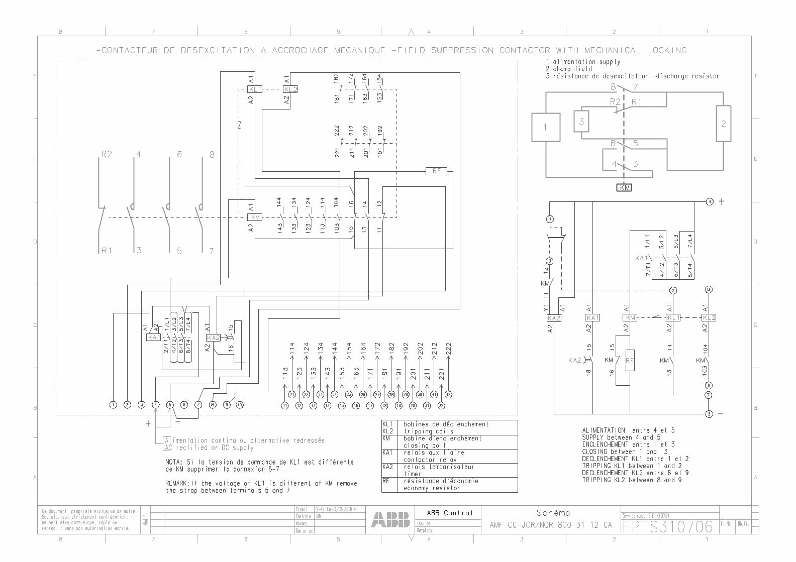
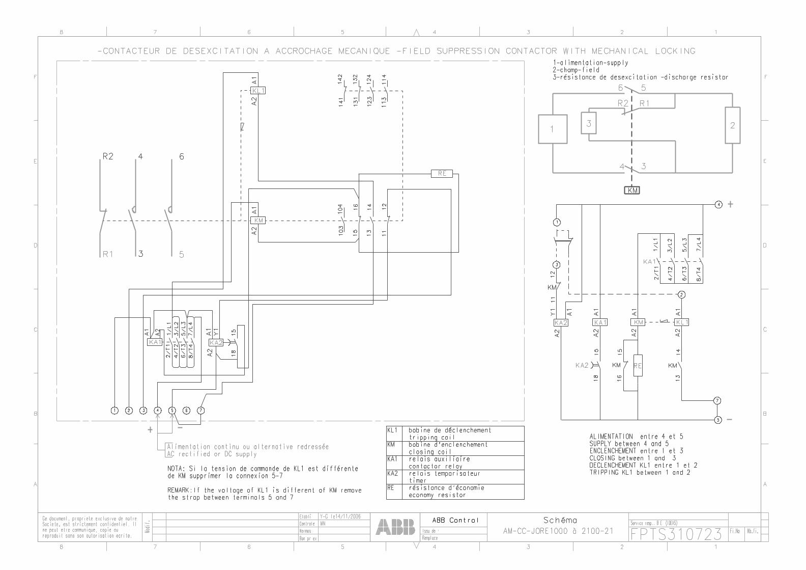
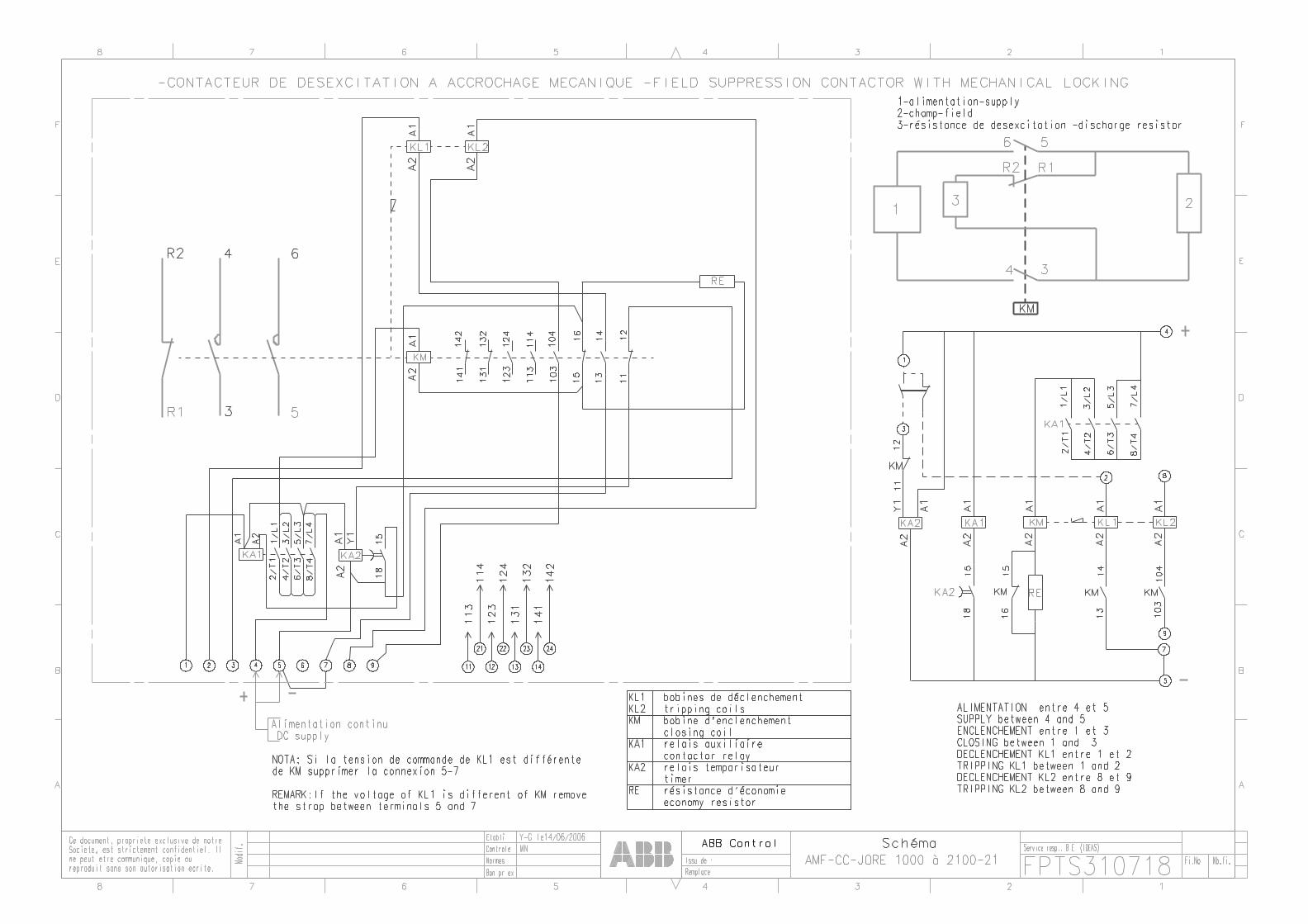
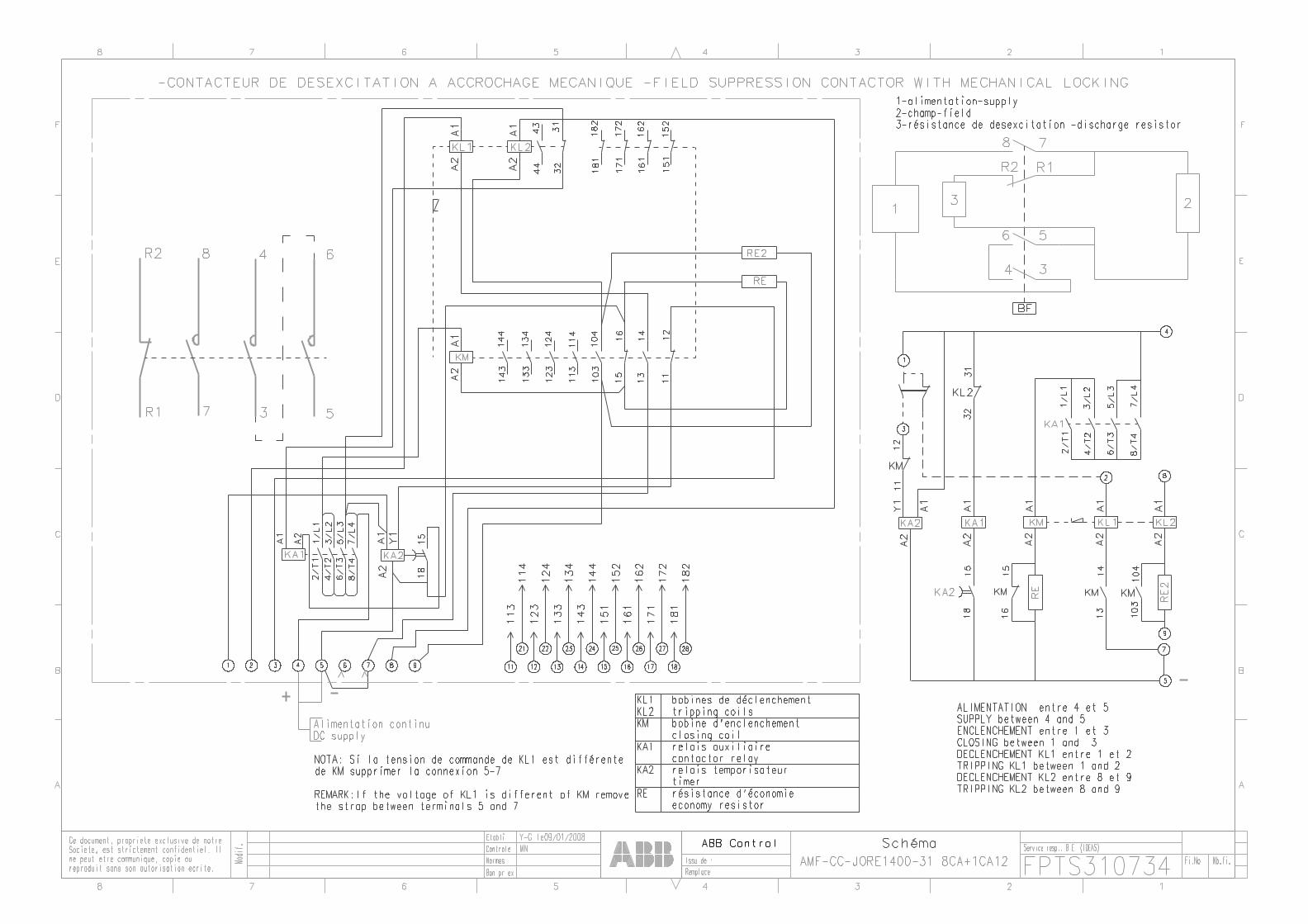
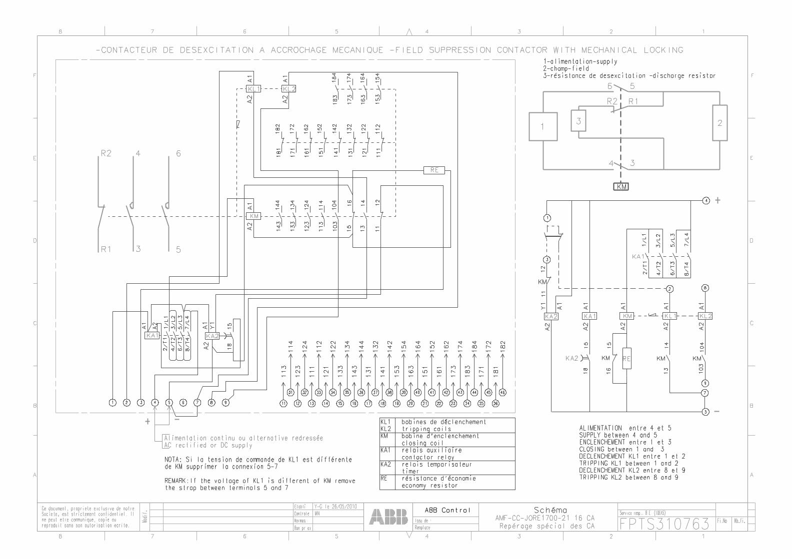
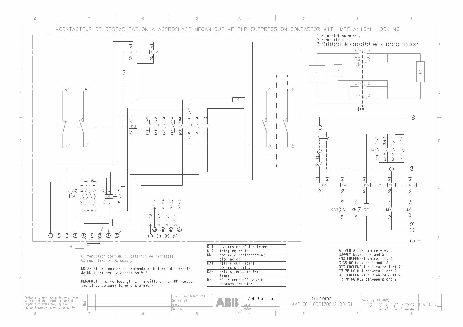
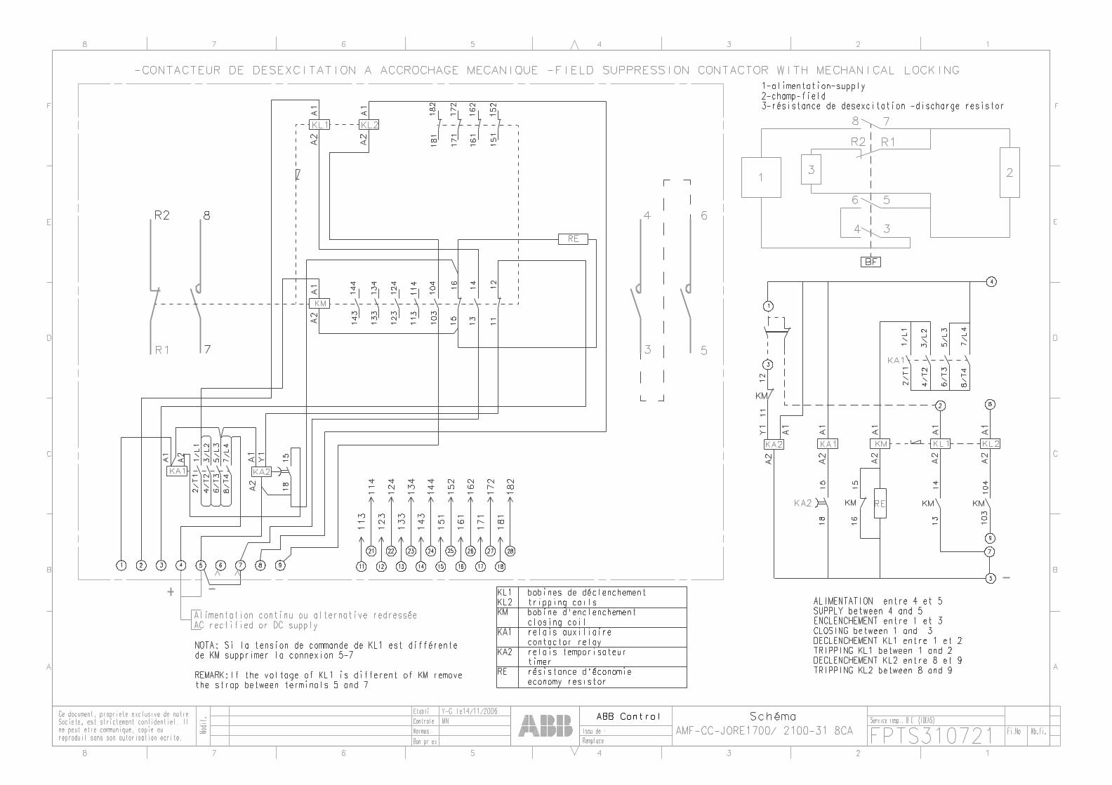
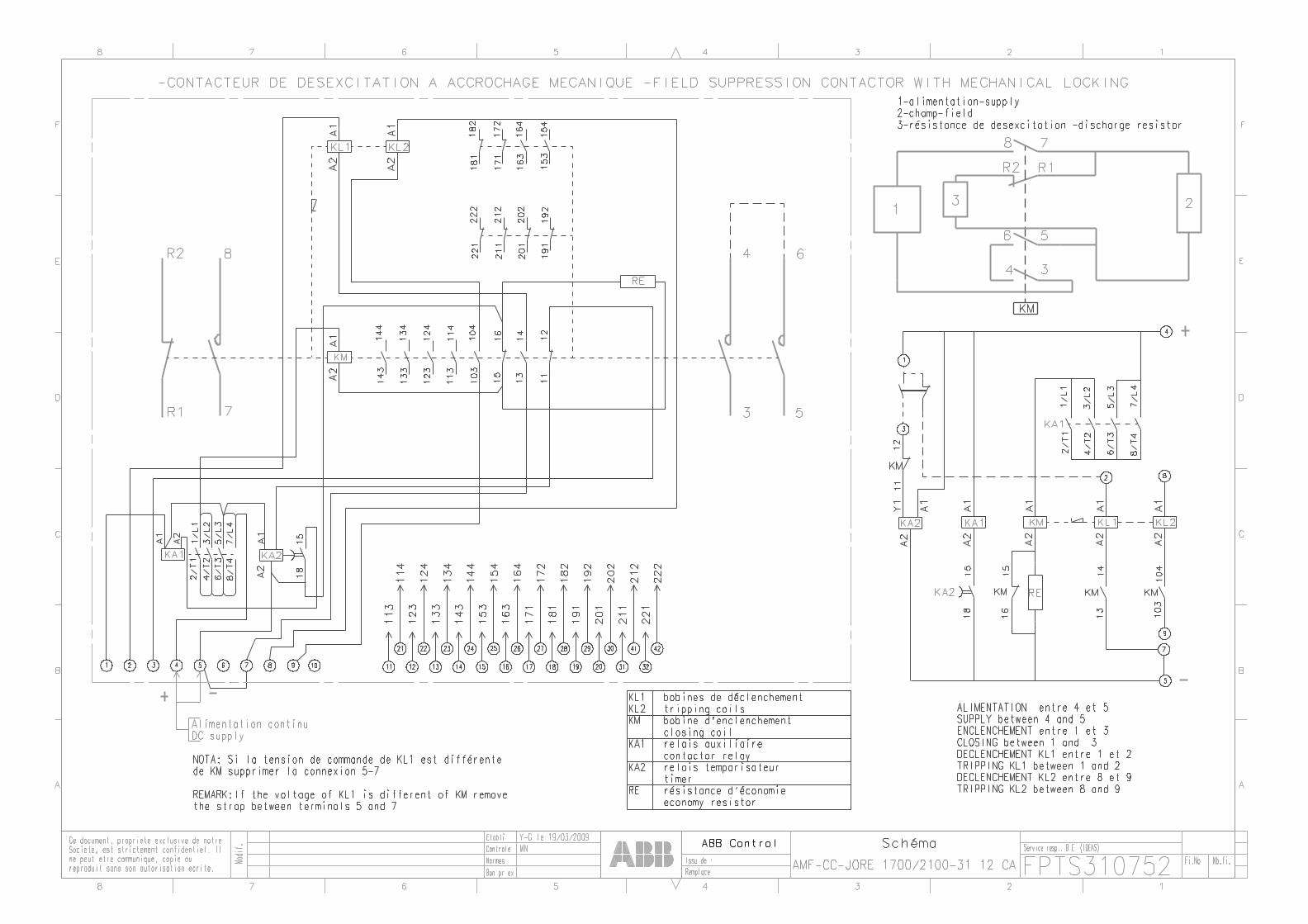
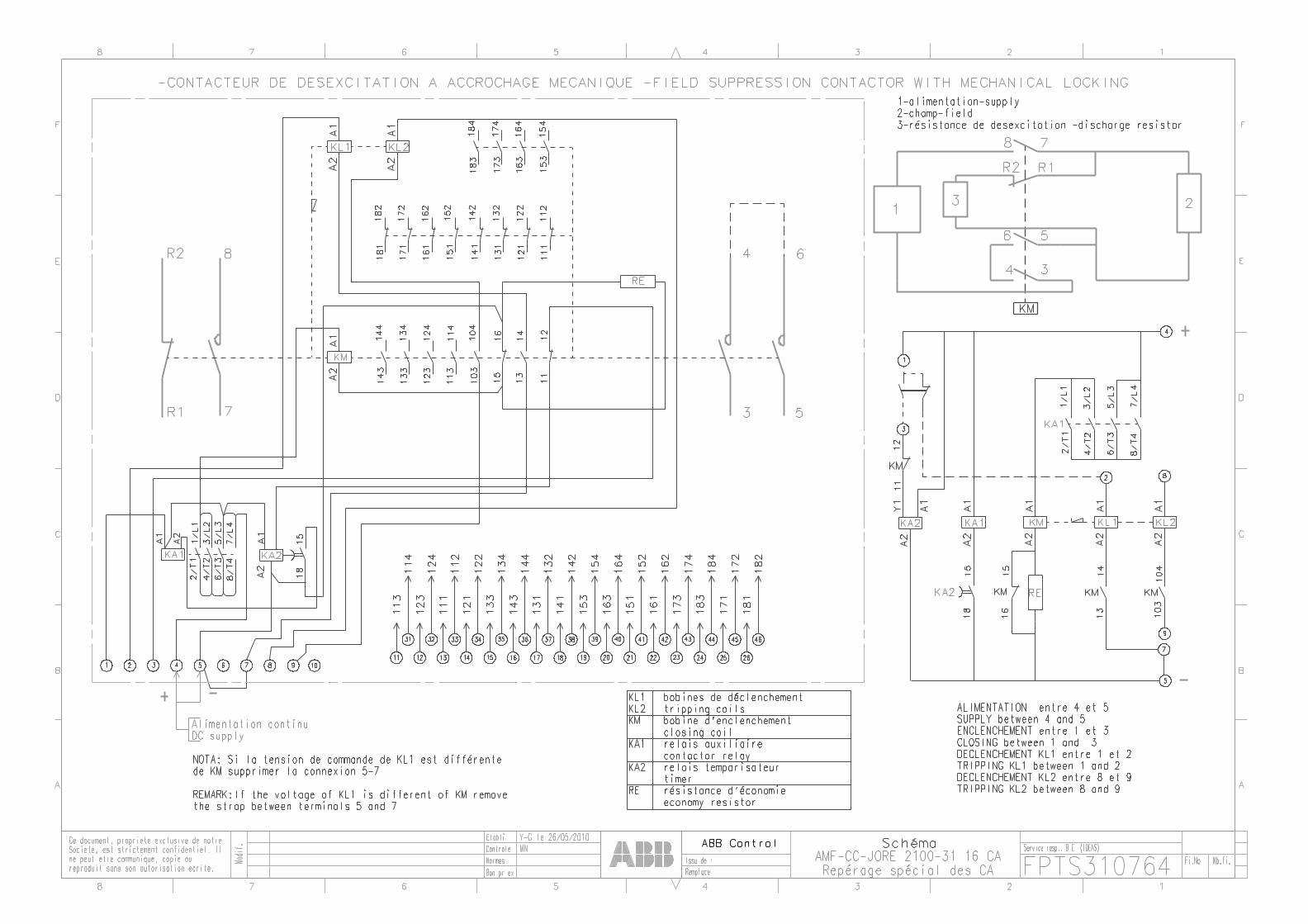
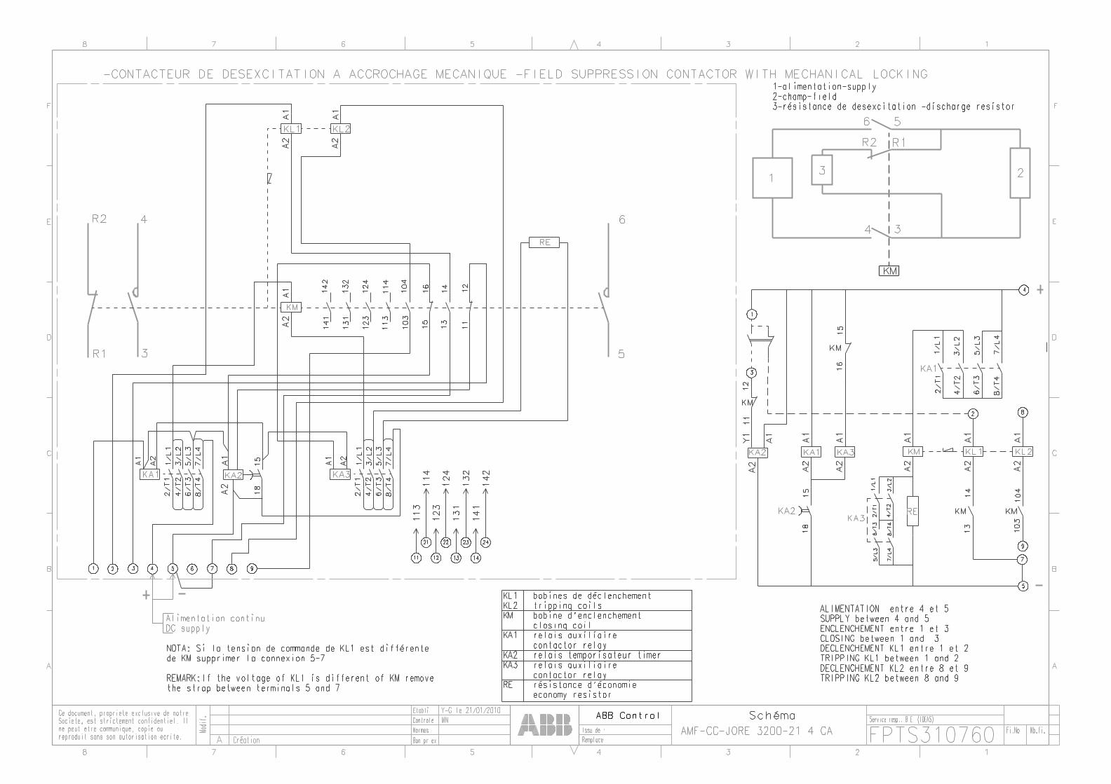
Wiring Diagrams
Schémas électriques
Contents / Sommaire
- AM-CC- NOR63-21/31 , AM-CC-NOR125-21/31
- AM-CC-NOR200-21/31
- AM-CC-NOR500-21/31
- AM(F)-CC-JORE550-21/31
- AM(F)-CC-JORE800-21/31
- AM(F)-CC-JORE1000-21/31
- AM(F)-CC-JORE1400-21/31
- AM(F)-CC-JORE1700-21/31
- AM(F)-CC-JORE2100-21/31
- AM(F)-CC-JORE2500-21/31
- AM(F)-CC-JORE3200-21/31 6
- AM(F)-CC-JORE3800-21/31
- AM(F)-CC-JORE4500-21


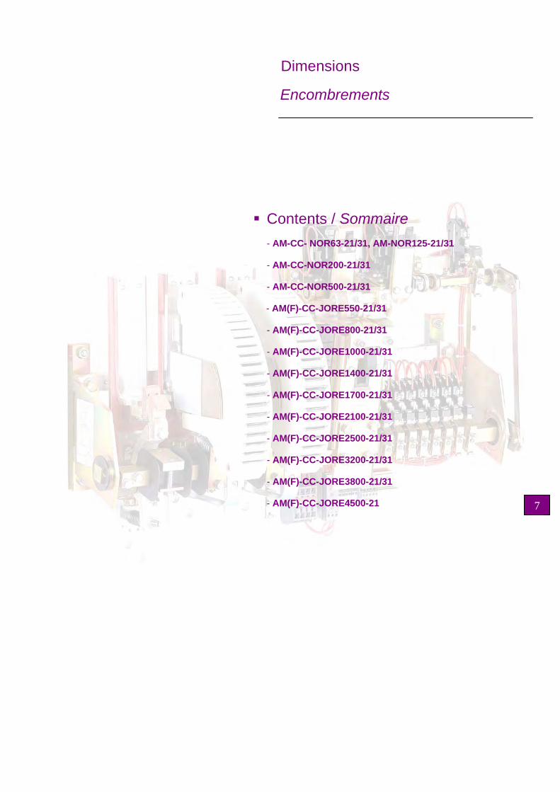
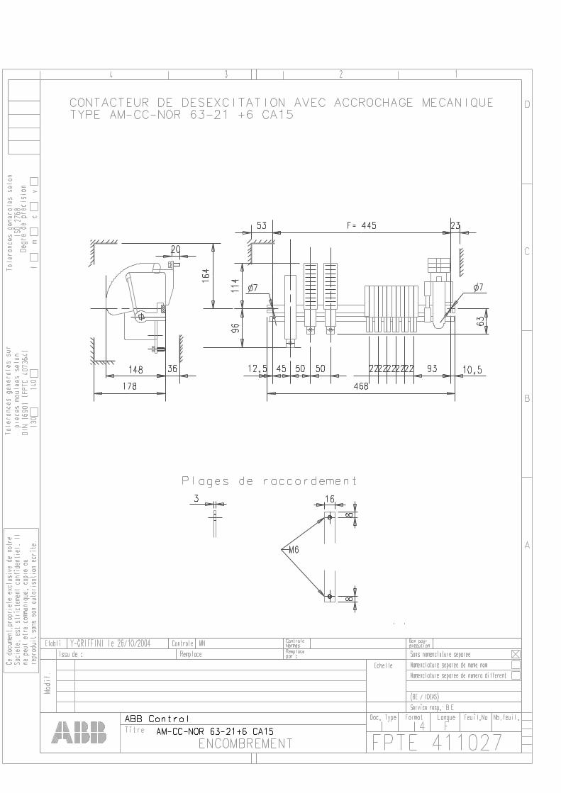
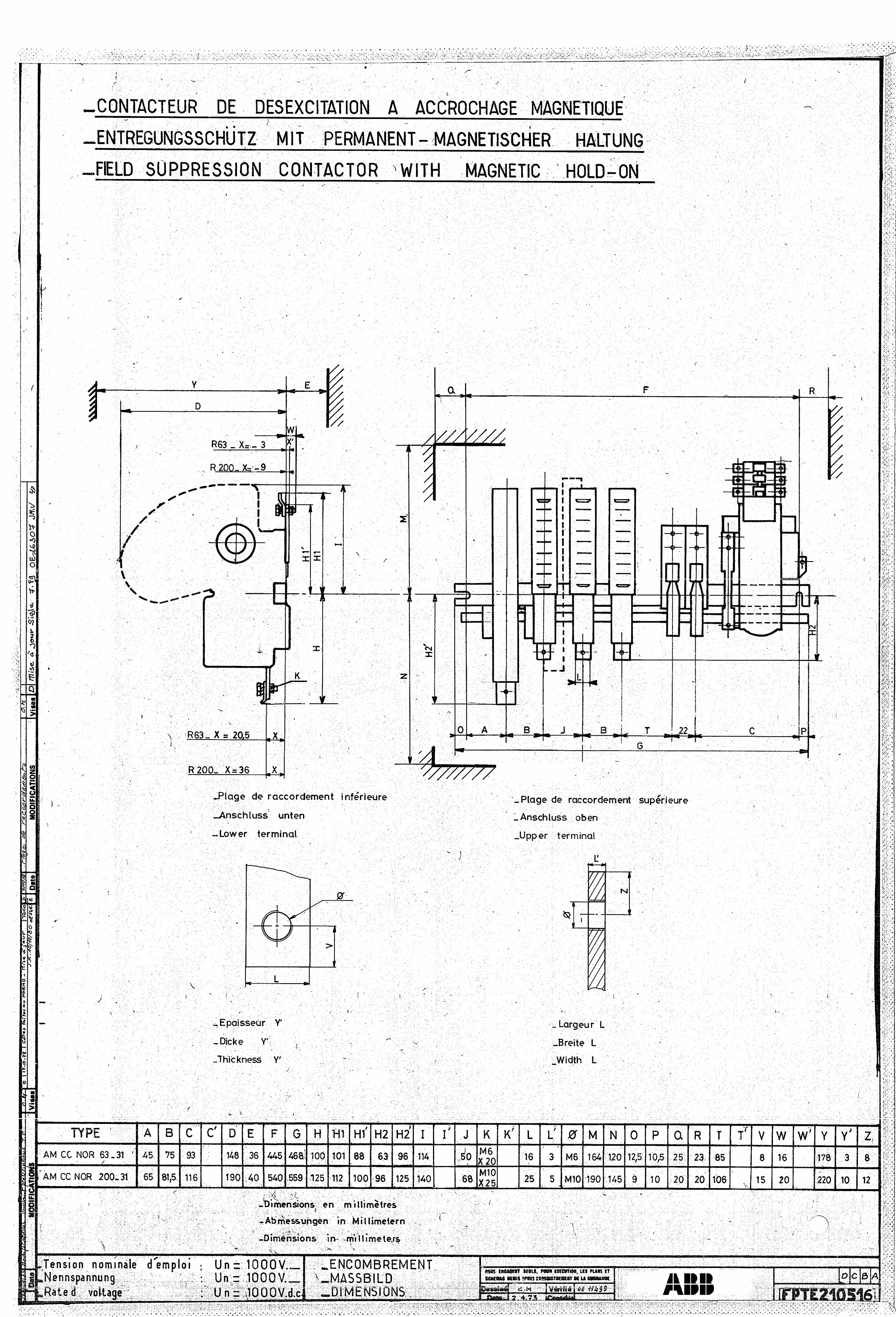
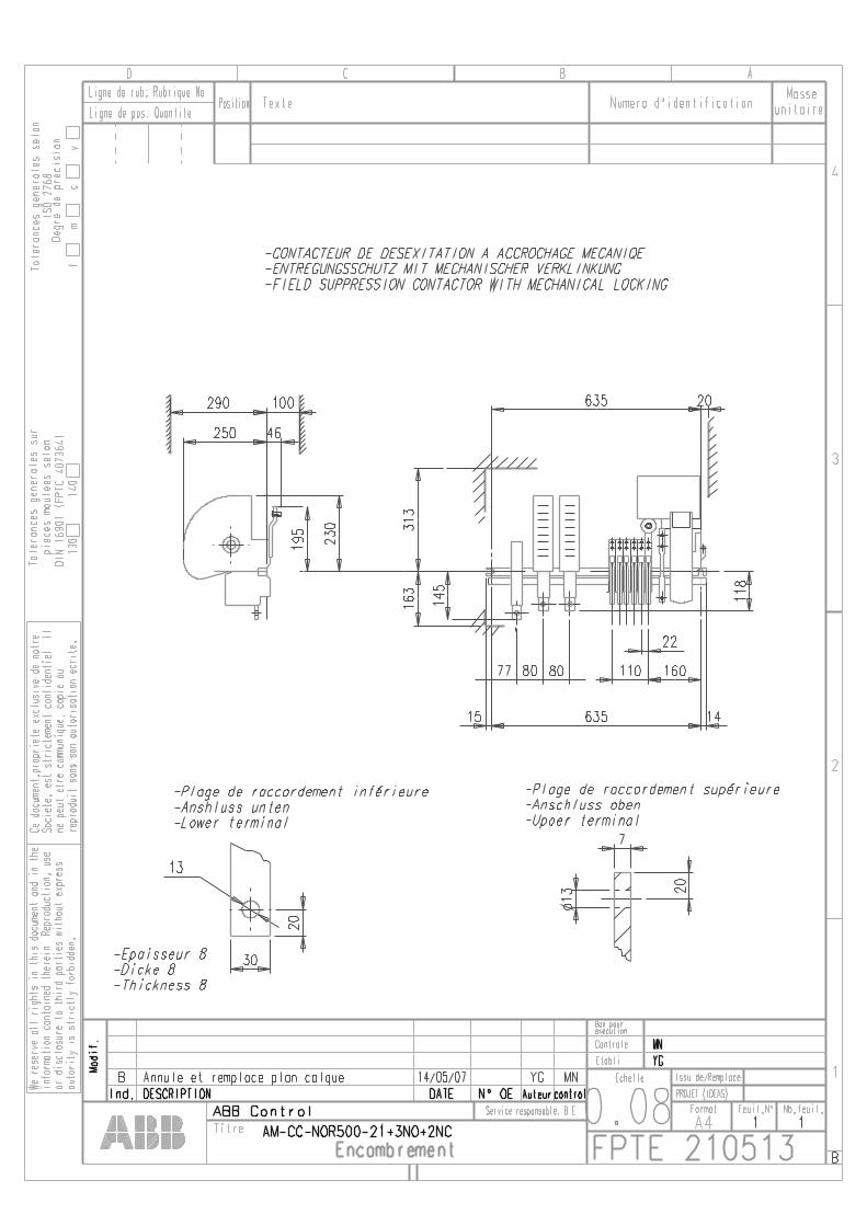
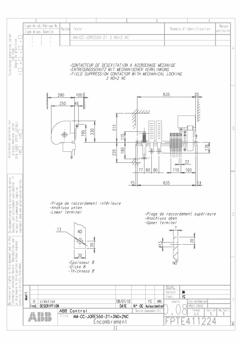
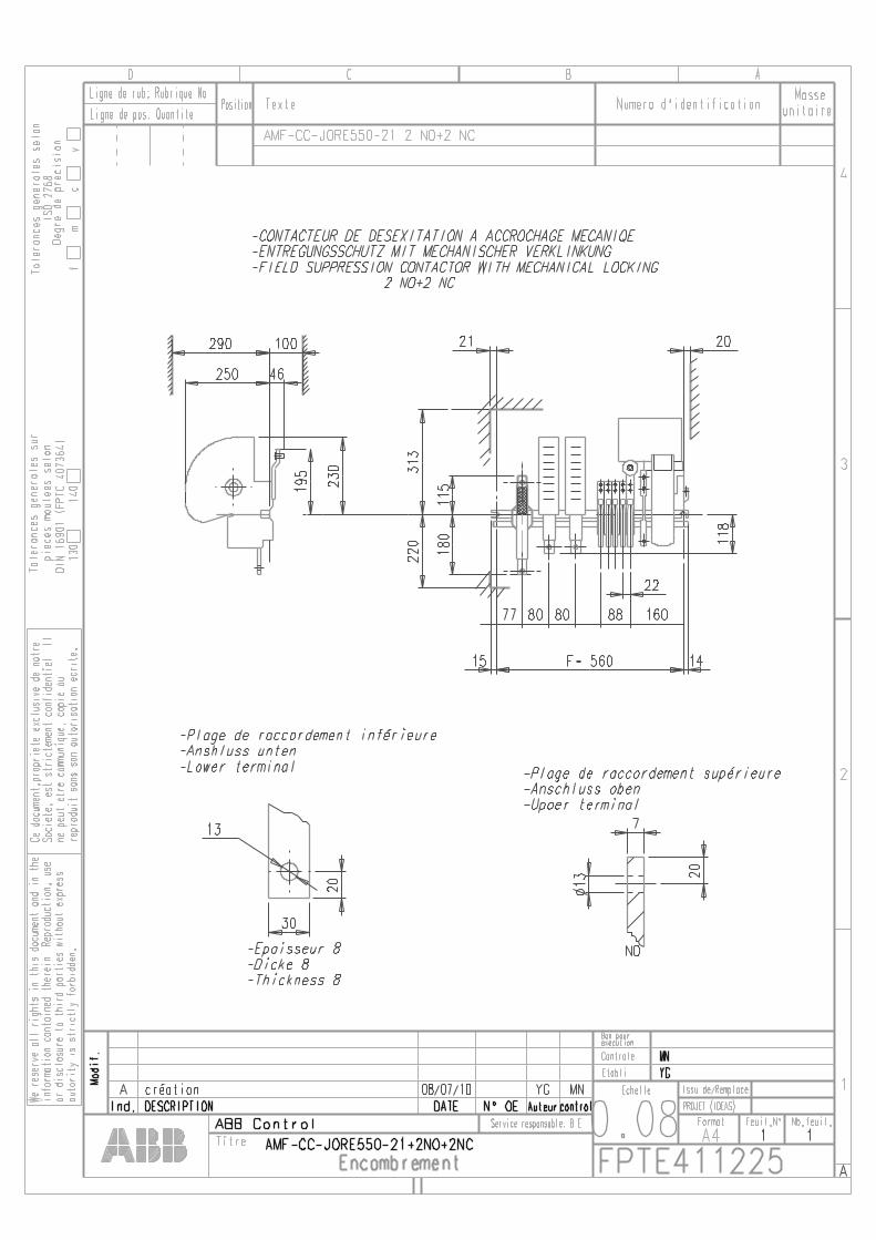
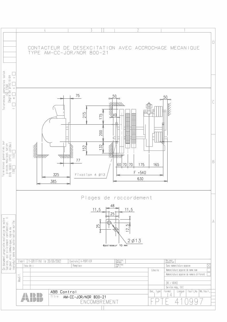
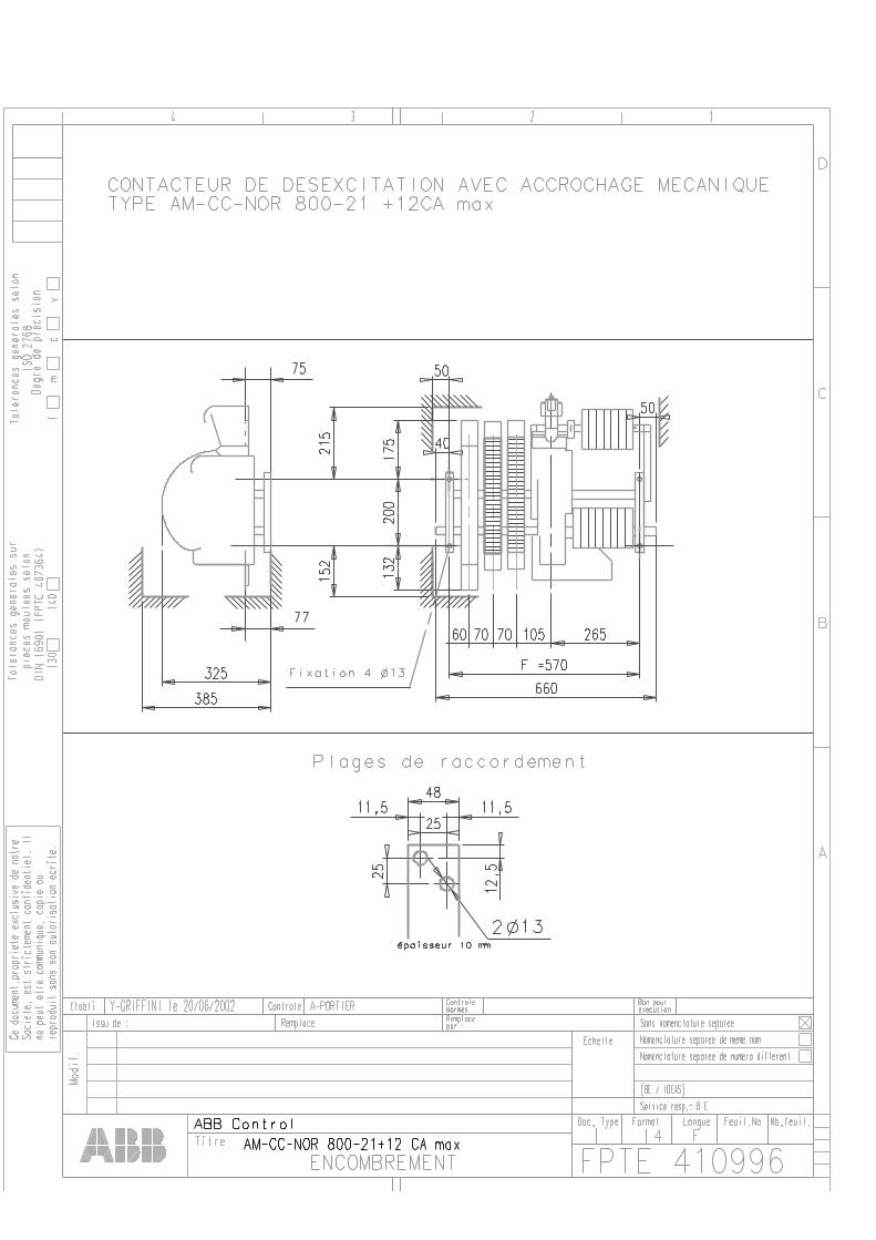
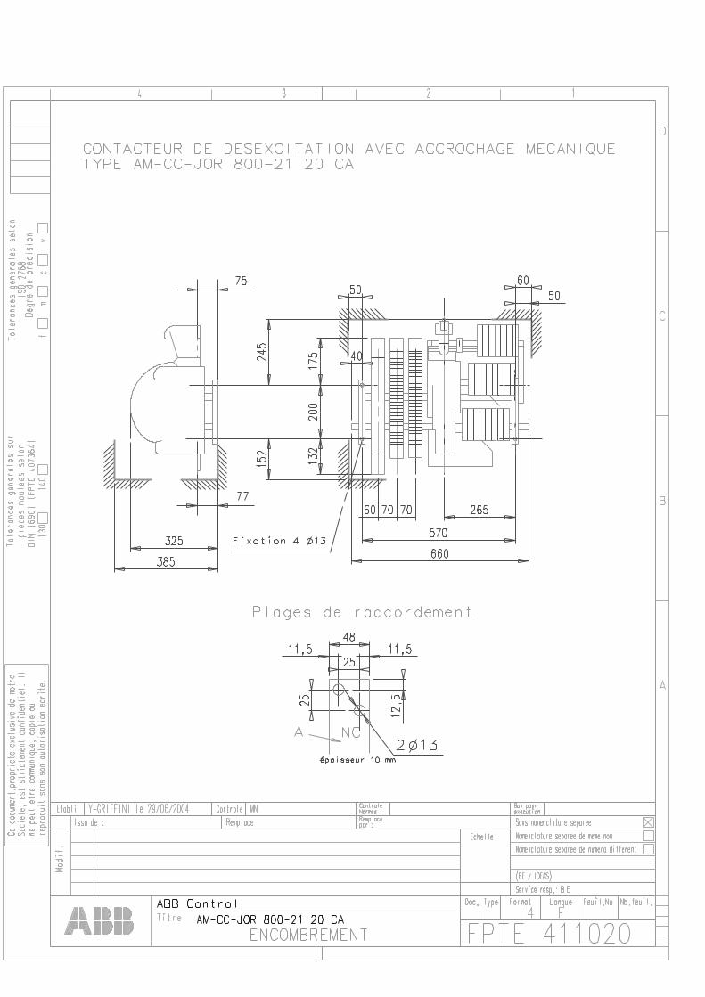
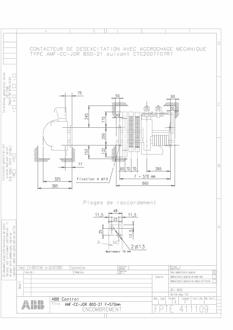
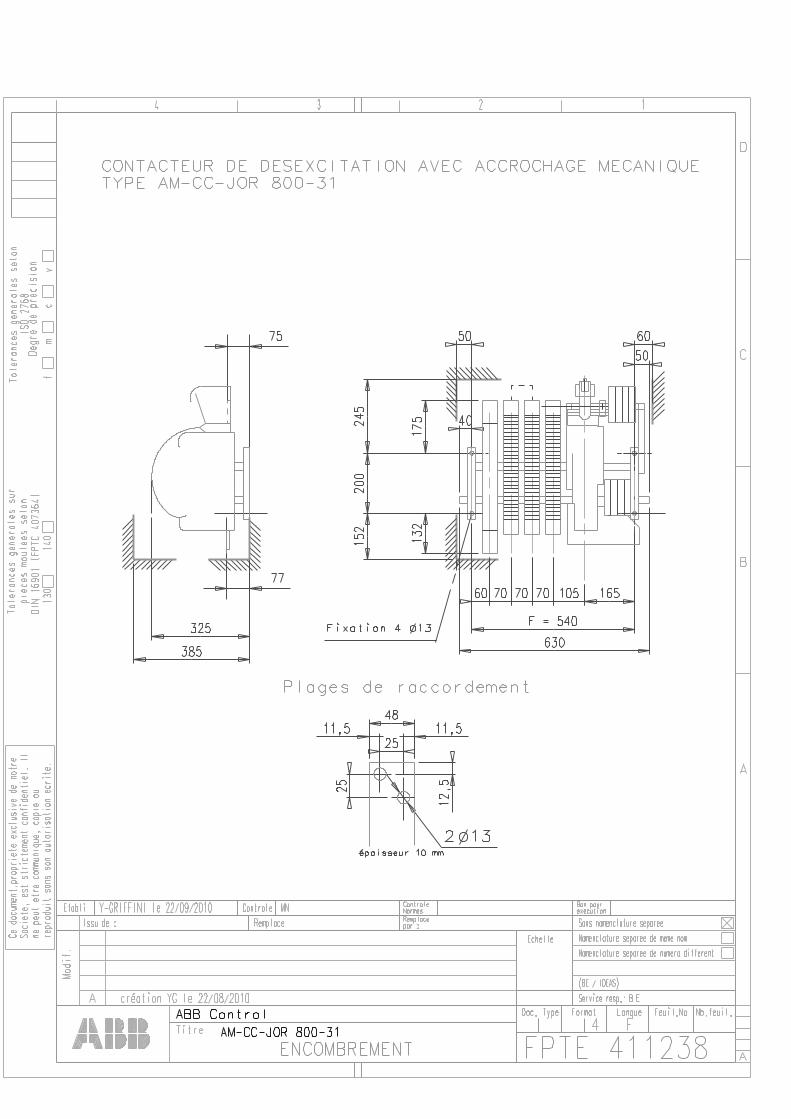
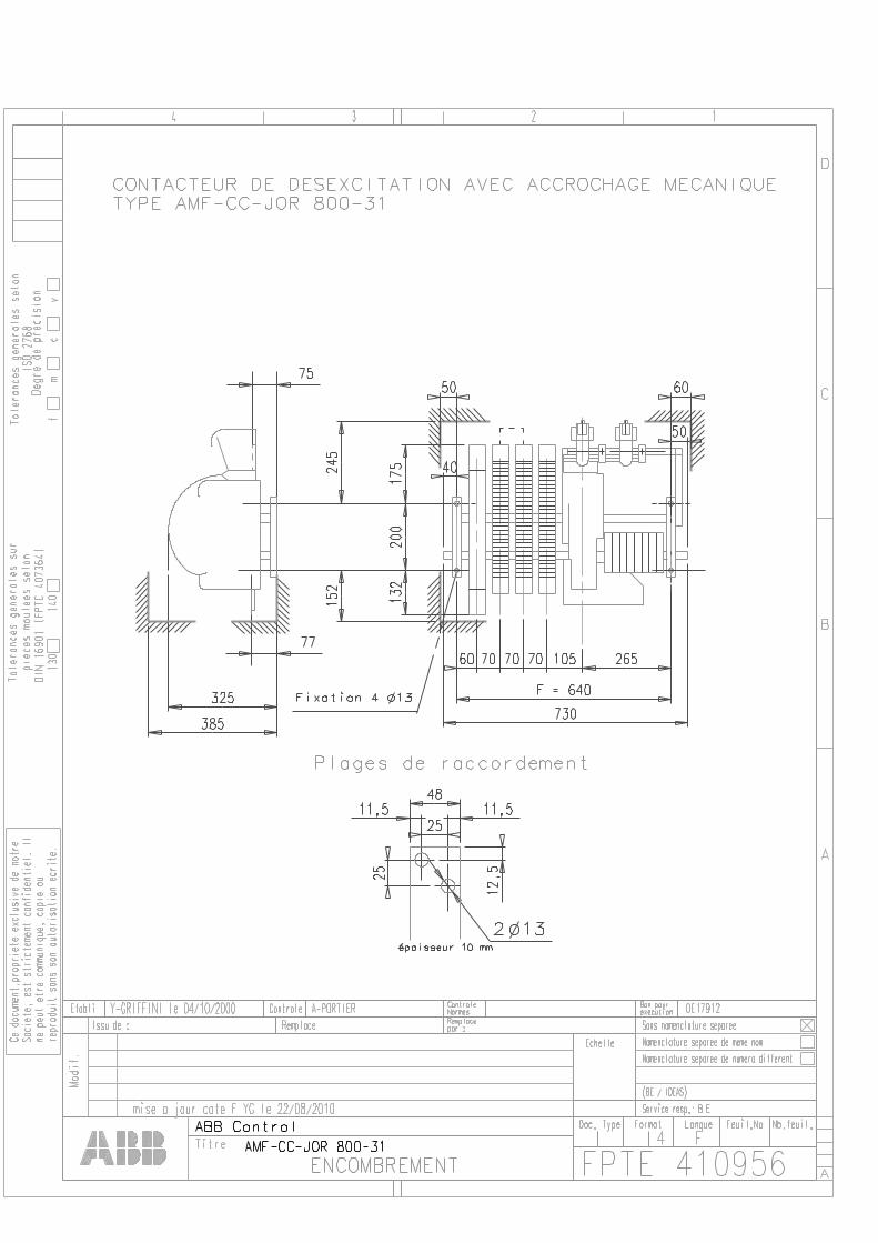
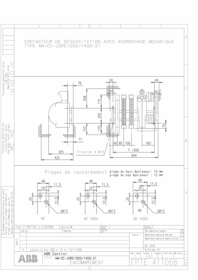
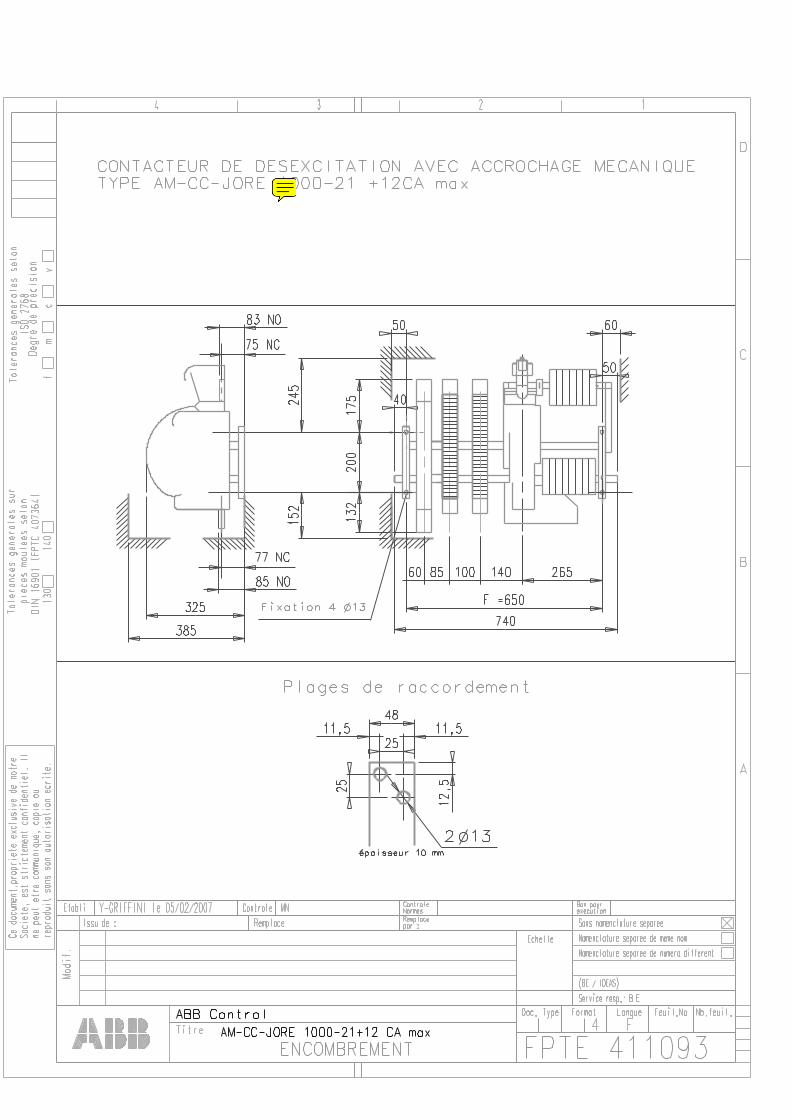
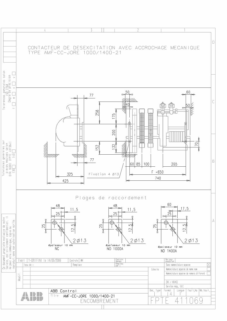
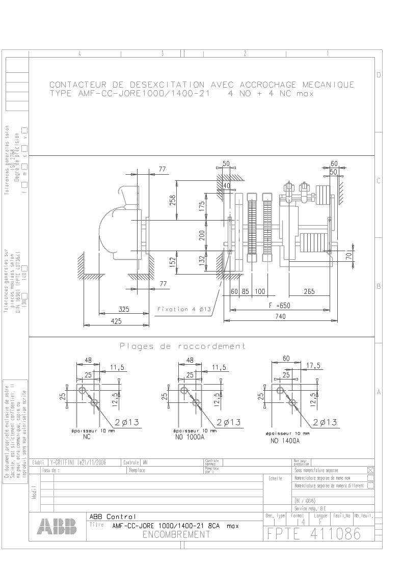
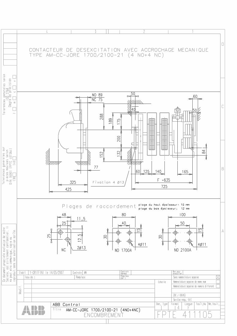
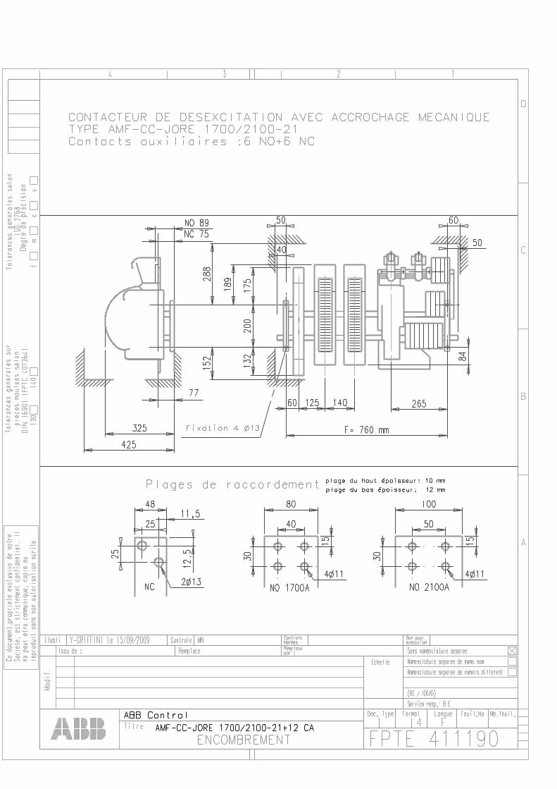
Dimensions
Encombrements
Contents / Sommaire
- AM-CC- NOR63-21/31, AM-NOR125-21/31
- AM-CC-NOR200-21/31
- AM-CC-NOR500-21/31
- AM(F)-CC-JORE550-21/31
- AM(F)-CC-JORE800-21/31
- AM(F)-CC-JORE1000-21/31
- AM(F)-CC-JORE1400-21/31
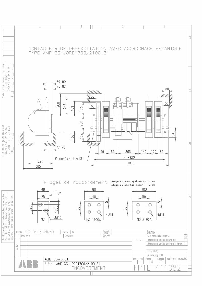
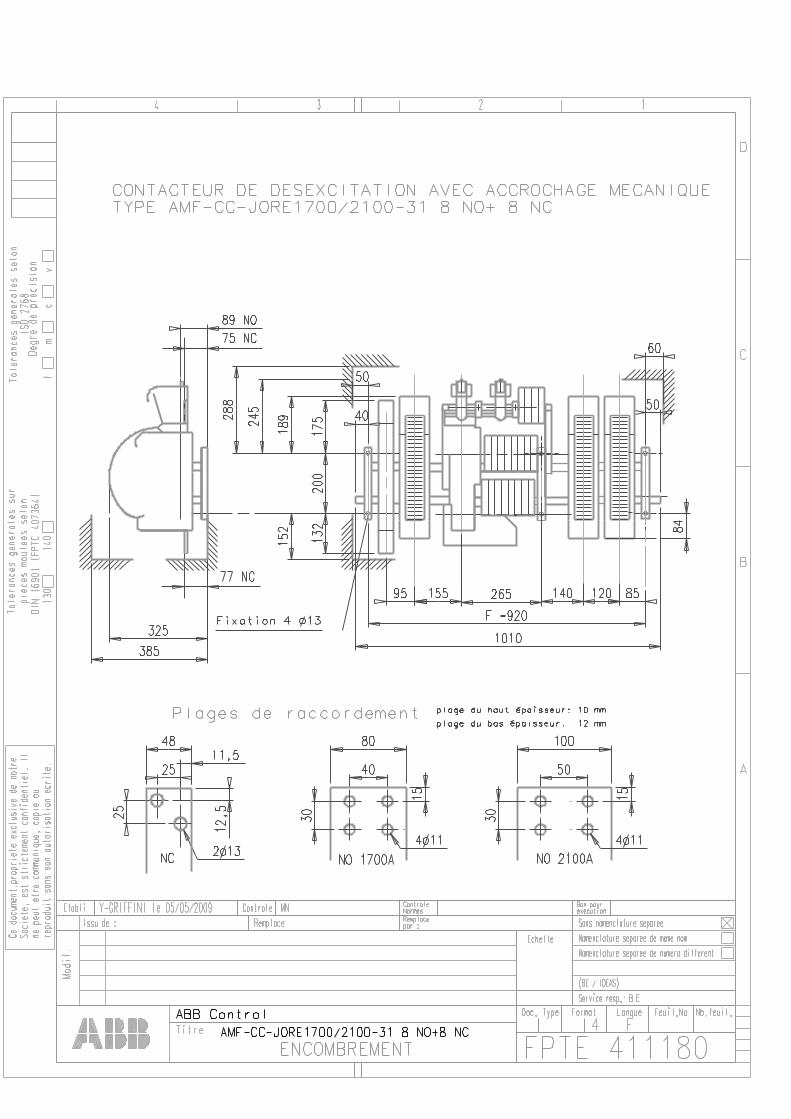
- AM(F)-CC-JORE1700-21/31
- AM(F)-CC-JORE2100-21/31
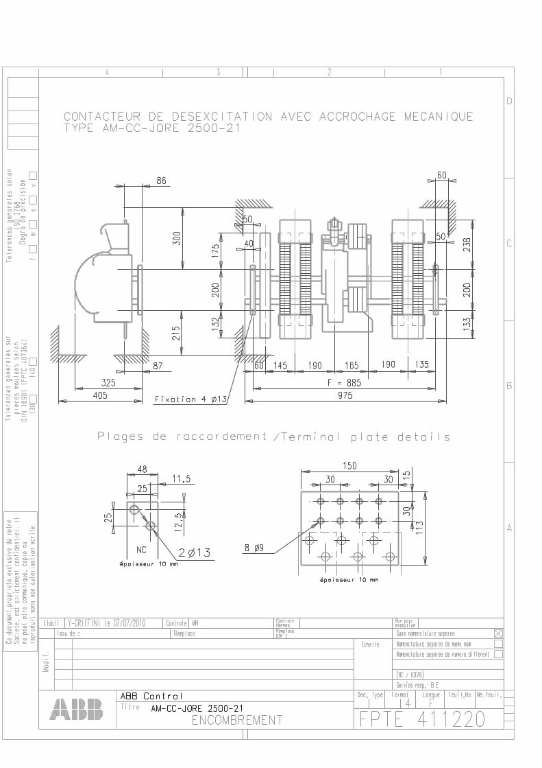
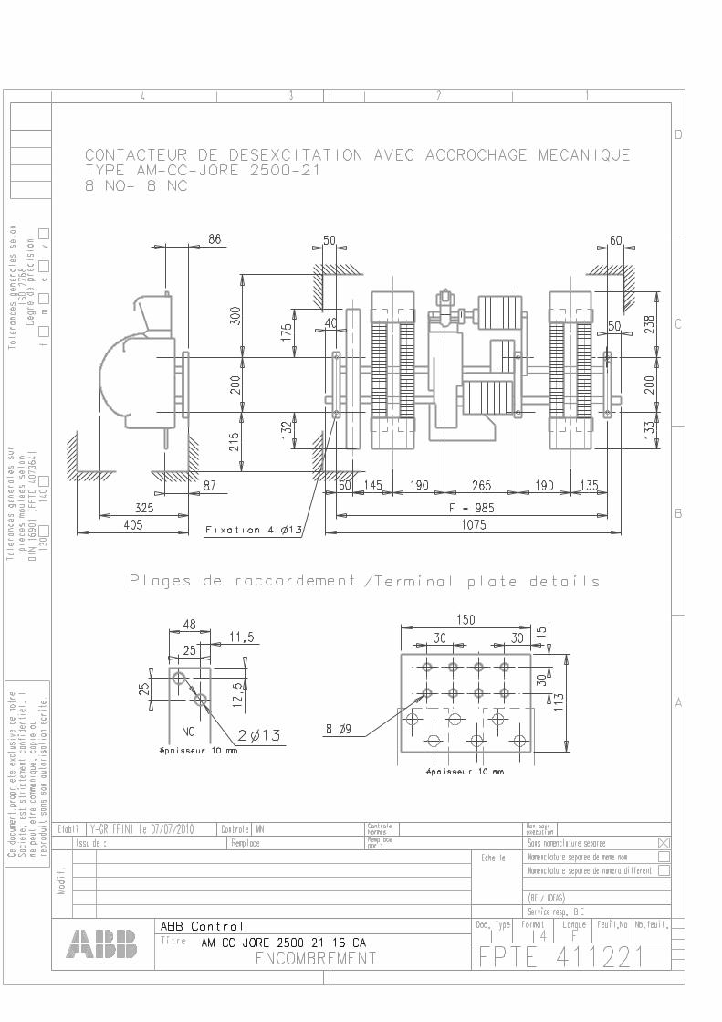
- AM(F)-CC-JORE2500-21/31
- AM(F)-CC-JORE3200-21/31
- AM(F)-CC-JORE3800-21/31
7- AM(F)-CC-JORE4500-21


![Open Field Network CC-Link Troubleshooting …...7 [14] CC-Link Version: Confirm that the parameter settings match with the “CC-Link" when using the Ver. 1.10 compatible product,](https://img.pdfslide.us/doc/110x75/5ec8f342383a8725897caf37/open-field-network-cc-link-troubleshooting-7-14-cc-link-version-confirm-that.jpg)