Embed Size (px)
Citation preview
AMCA MEMBER
Tunnel Ventilation, Smoke Control, & Fire Dampers Technical Information
American Warming and Ventilating
A Mestek Company
2
American Warming and Ventilating, 7301 International Drive, Holland, Ohio 43528, USA
www.awv.com | Phone: 419-865-5000 | Fax: 419-865-1375
3
AWV Profile ................................................................. 4
Damper Performance and Selection ......................... 6
TFD-75 and TFD-75i Dampers .................................... 7
TFD-75/TFD-75i Standard Specification ....................... 8
TFD-75/TFD-75i Performance Testing ......................... 10
EAF-75 Damper ........................................................12
EAF-75 Standard Specification ................................. 13
VC-51 Damper Specification ................................... 14
Client List at a Glance ..............................................16
Table of ContentsTunnel Ventilation, Smoke Control, & Fire Dampers
4
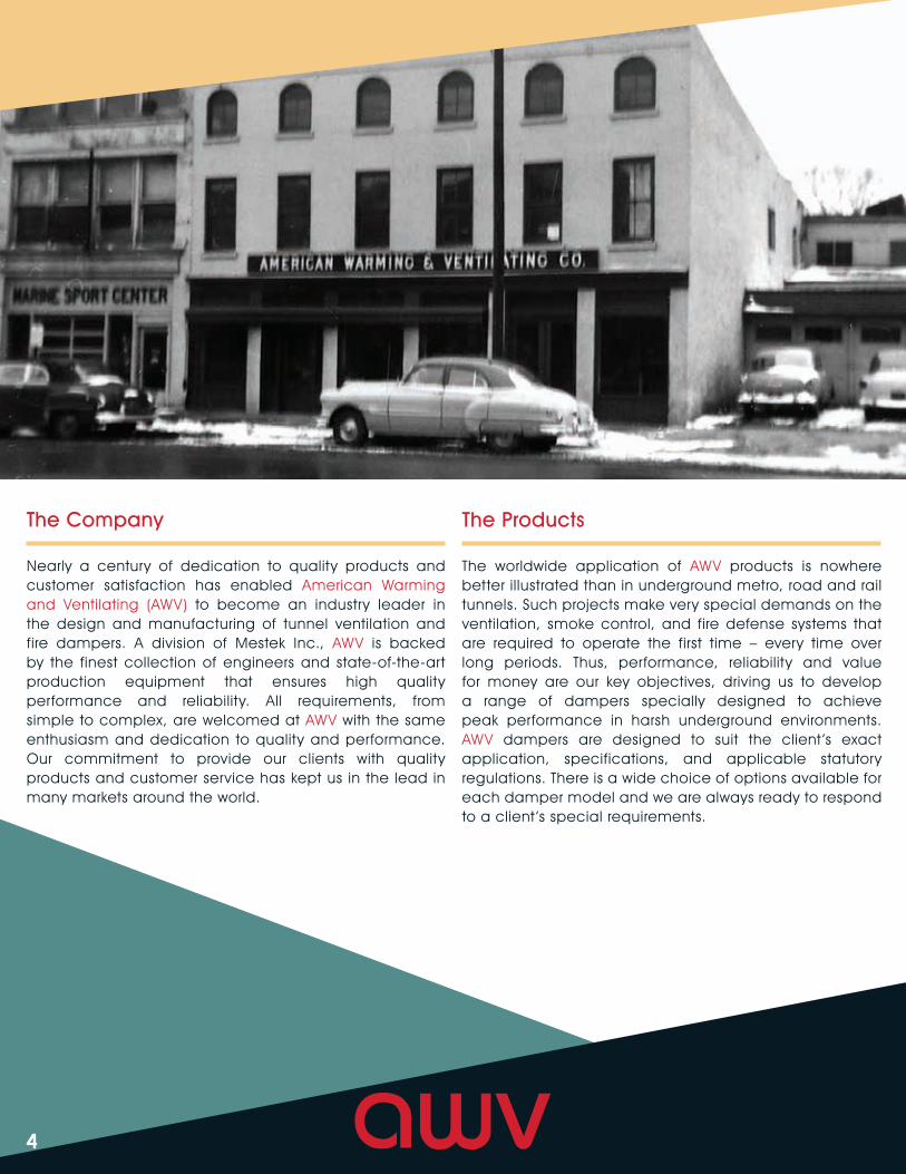
Nearly a century of dedication to quality products and customer satisfaction has enabled American Warming and Ventilating (AWV) to become an industry leader in the design and manufacturing of tunnel ventilation and fire dampers. A division of Mestek Inc., AWV is backed by the finest collection of engineers and state-of-the-art production equipment that ensures high quality performance and reliability. All requirements, from simple to complex, are welcomed at AWV with the same enthusiasm and dedication to quality and performance. Our commitment to provide our clients with quality products and customer service has kept us in the lead in many markets around the world.
The Company
The worldwide application of AWV products is nowhere better illustrated than in underground metro, road and rail tunnels. Such projects make very special demands on the ventilation, smoke control, and fire defense systems that are required to operate the first time – every time over long periods. Thus, performance, reliability and value for money are our key objectives, driving us to develop a range of dampers specially designed to achieve peak performance in harsh underground environments. AWV dampers are designed to suit the client ’s exact application, specifications, and applicable statutory regulations. There is a wide choice of options available for each damper model and we are always ready to respond to a client ’s special requirements.
The Products
5
AWV has been manufacturing dampers for decades. Our dampers are operating reliably in many countries around the world in metros, road and rail tunnels, as well as in nuclear and fossil fuel power stations, refineries, ships, offshore oil and gas platforms, and military establishments.
Our dampers are found in diverse parts of the world such as:
• England (Jubilee Line Extension)
• Italy (Monte Bianco Tunnel)
• Taiwan (Panchiao Line Tunnel)
• Australia (Graham Farmer Freeway)
• India (Mandhi House Station)
• Venezuela (Caracas Metro Line 3.2)
• USA (World Trade Center)
Of course the benefit of this experience is freely available to our clients, whether it is advice on specifications, performance data, testing, corrosion resistance or any other aspect of damper design and performance.
American Warming and Ventilating: Unparalleled Experience
AWV’s Quality Assurance Program has been developed to meet the intent of 10CFR50 Appendix B, American National Standards Institute (ANSI) N45.2 and NQA-1, and Military Specifications MIL-1-45208A (Quality Program) and MIL-STD-45662A (Calibrations). Weld procedures and welder performance qualifications meet the requirements of the American Welding Society Codes DI.1, DI.2, DI.3 and the American Society of Mechanical Engineers (ASME) Section IX.
Quality Assurance
Through a continuous program of research and development, AWV tunnel dampers undergo stringent testing often witnessed by our clients, engineering firms, and internationally recognized certifying bodies.
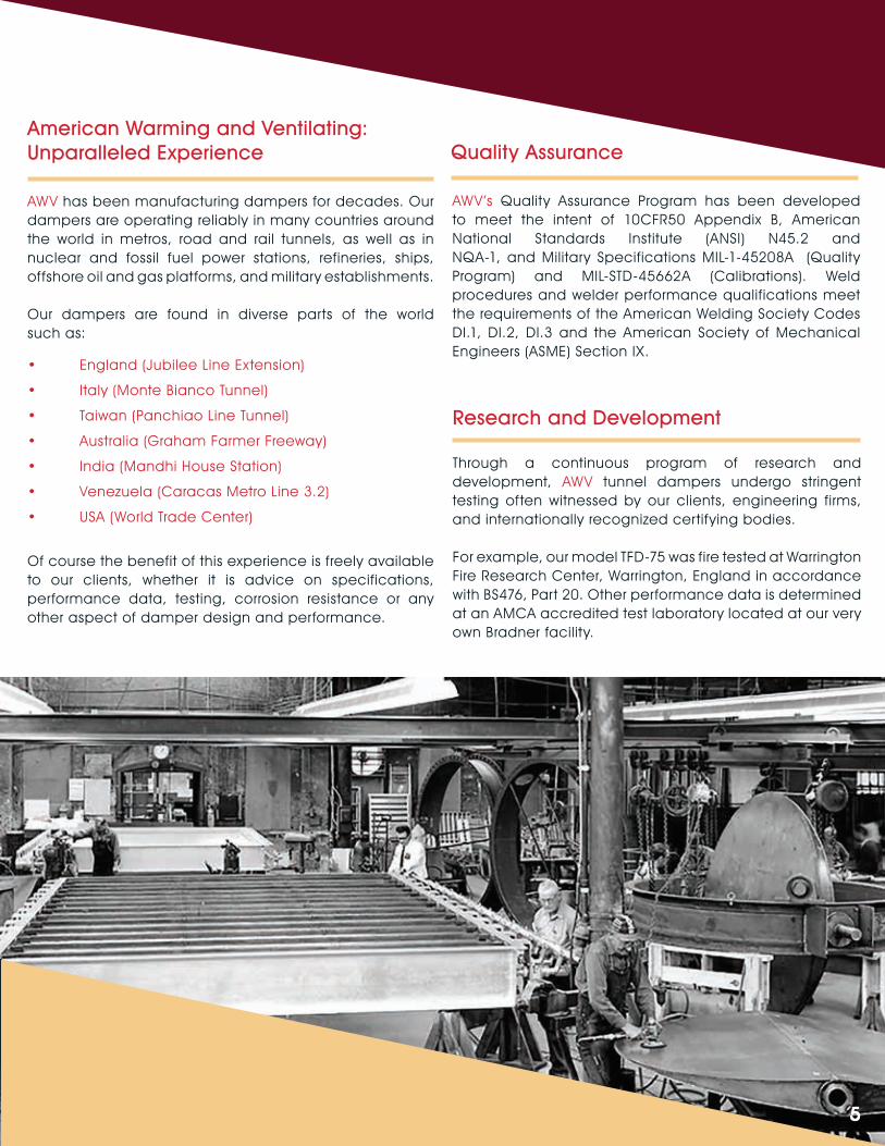
For example, our model TFD-75 was fire tested at Warrington Fire Research Center, Warrington, England in accordance with BS476, Part 20. Other performance data is determined at an AMCA accredited test laboratory located at our very own Bradner facility.
Research and Development
6
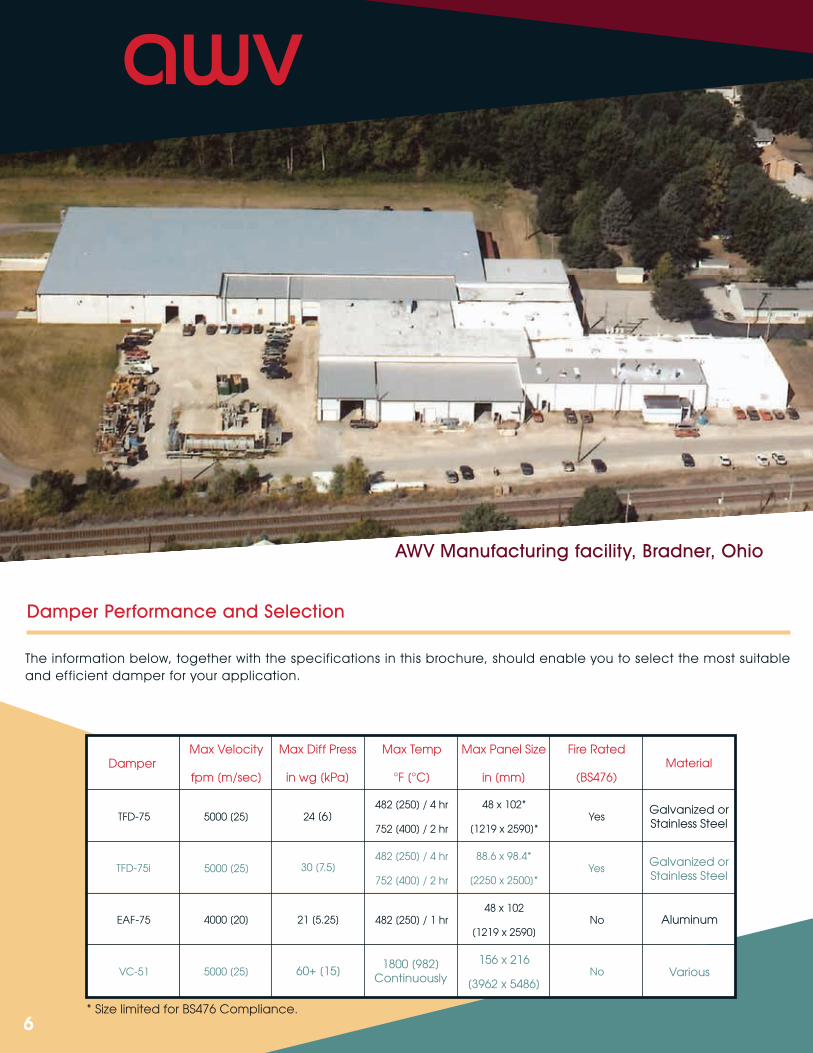
The information below, together with the specifications in this brochure, should enable you to select the most suitable and efficient damper for your application.
Damper Performance and Selection
AWV Manufacturing facility, Bradner, Ohio
7
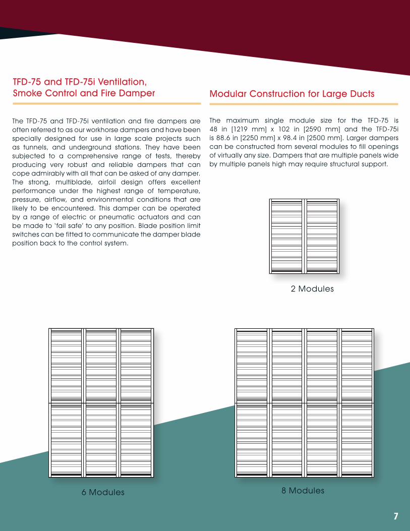
Modular Construction for Large DuctsTFD-75 and TFD-75i Ventilation, Smoke Control and Fire Damper
The TFD-75 and TFD-75i ventilation and fire dampers are often referred to as our workhorse dampers and have been specially designed for use in large scale projects such as tunnels, and underground stations. They have been subjected to a comprehensive range of tests, thereby producing very robust and reliable dampers that can cope admirably with all that can be asked of any damper. The strong, multiblade, airfoil design offers excellent performance under the highest range of temperature, pressure, airflow, and environmental conditions that are likely to be encountered. This damper can be operated by a range of electric or pneumatic actuators and can be made to ‘ fail safe’ to any position. Blade position limit switches can be fitted to communicate the damper blade position back to the control system.
The maximum single module size for the TFD-75 is 48 in [1219 mm] x 102 in [2590 mm] and the TFD-75i is 88.6 in [2250 mm] x 98.4 in [2500 mm]. Larger dampers can be constructed from several modules to fill openings of virtually any size. Dampers that are multiple panels wide by multiple panels high may require structural support.
2 Modules
6 Modules 8 Modules
8
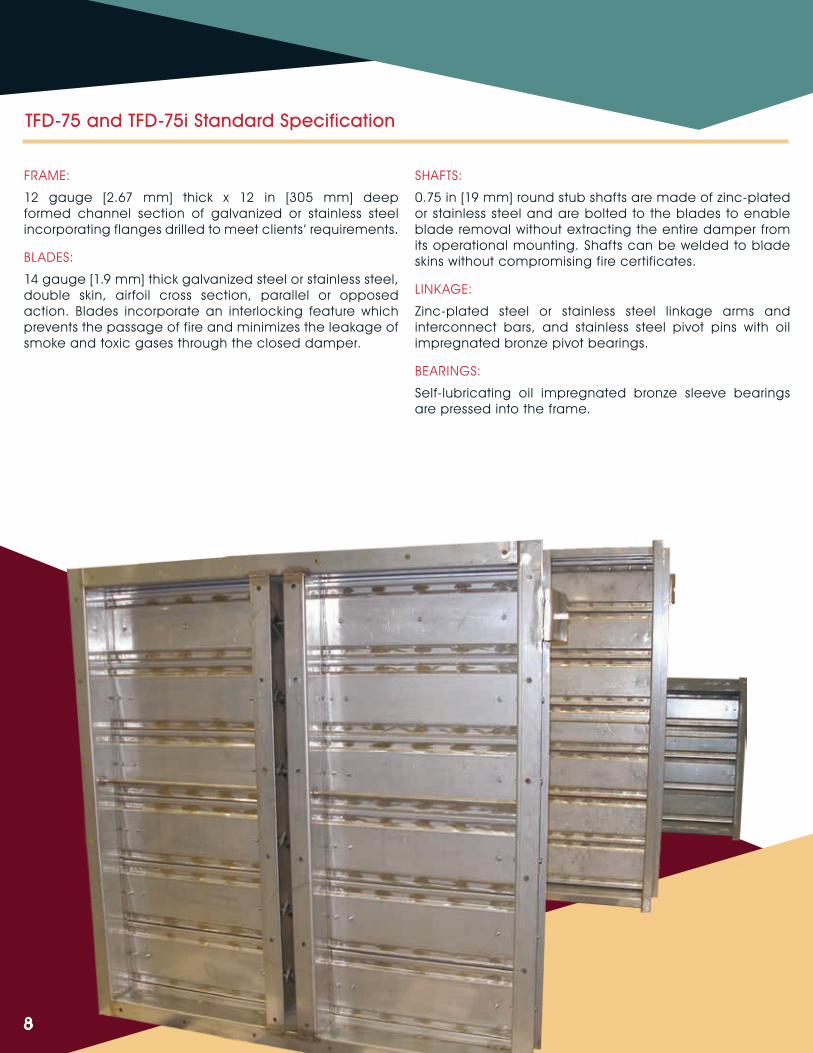
TFD-75 and TFD-75i Standard Specification
FRAME:
12 gauge [2.67 mm] thick x 12 in [305 mm] deep formed channel section of galvanized or stainless steel incorporating flanges drilled to meet clients’ requirements.
BLADES:
14 gauge [1.9 mm] thick galvanized steel or stainless steel, double skin, airfoil cross section, parallel or opposed action. Blades incorporate an interlocking feature which prevents the passage of fire and minimizes the leakage of smoke and toxic gases through the closed damper.
SHAFTS:
0.75 in [19 mm] round stub shafts are made of zinc-plated or stainless steel and are bolted to the blades to enable blade removal without extracting the entire damper from its operational mounting. Shafts can be welded to blade skins without compromising fire certificates.
LINKAGE:
Zinc-plated steel or stainless steel linkage arms and interconnect bars, and stainless steel pivot pins with oil impregnated bronze pivot bearings.
BEARINGS:
Self-lubricating oil impregnated bronze sleeve bearings are pressed into the frame.
9
The TFD-75 is currently in use within the English Channel Rail Link “Chunnel” in the UK, Florida’s Port of Miami vehicular tunnel in the US, the Republic of Columbia’s Runnel San Jeronimo tunnel in Columbia, and many more locations across the globe.
The TFD-75i is our newest model and is currently in use on India’s Delhi Metro Phase 3.
OPTIONS:
• Square shafts featuring heavy-duty oil impregnated bronze bearings that are housed in stainless steel casings. Linkage arms are bolted to the shafts. With this configuration the bearing and linkage arms are removable from outside the damper frame while the damper remains in service.
• Continuous shafts are also available.
• Blade and jamb seals can be fitted to further minimize the passage of air or smoke through the closed damper. Jamb seals are made from stainless steel while blade seals are made from silicone. UL555’s Class II leakage rate is standard for blade and jamb seals. Class I is available upon request.
• Actuators can be double acting pneumatic, spring return pneumatic, double acting electric, or spring return electric. All have been successfully tested for operation at 482°F [250°C] for a one-hour duration. Some actuators have been tested up to four hours. Please contact AWV for your exact requirements.
• Limit switches provide an independent set of contacts to give positive damper position indication at the fully open and fully closed positions. Switches have been tested for operation at 482°F [250°C] for four hours.
• Screens made of galvanized or stainless steel provide a safeguard against debris and rubbish from entering and damaging the fans and sound attenuators in a ventilation system.
TFD-75 and TFD-75i Standard Specification
• Structural supports are recommended for damper that are multiple panels wide by multiple panels high in order to maintain structural integrity against the dampers’ own weight and to resist distortion when installed. It is also recommended to minimize flexing when subjected to pulsating train-induced pressures.
• Mounting gaskets made from solid silicone compound can be supplied. These gaskets are good for continuous temperatures up to 482°F [250°C].
TESTING:
TFD-75 damper has been fire tested for four hours in accordance with BS476, Part 20 and IMO A754 (18) including Appendix 2 at Warrington Fire Research Center, England. Leakage and pressure drop performance were tested in accordance with AMCA 500-D Laboratory Methods of Testing Dampers for Rating.
STAINLESS STEEL:
Most steel fabrications and components can be manufactured from 304 or 316 stainless steel if required.
10
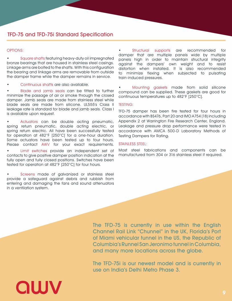
TFD-75 and TFD-75i Leakage Performance
11
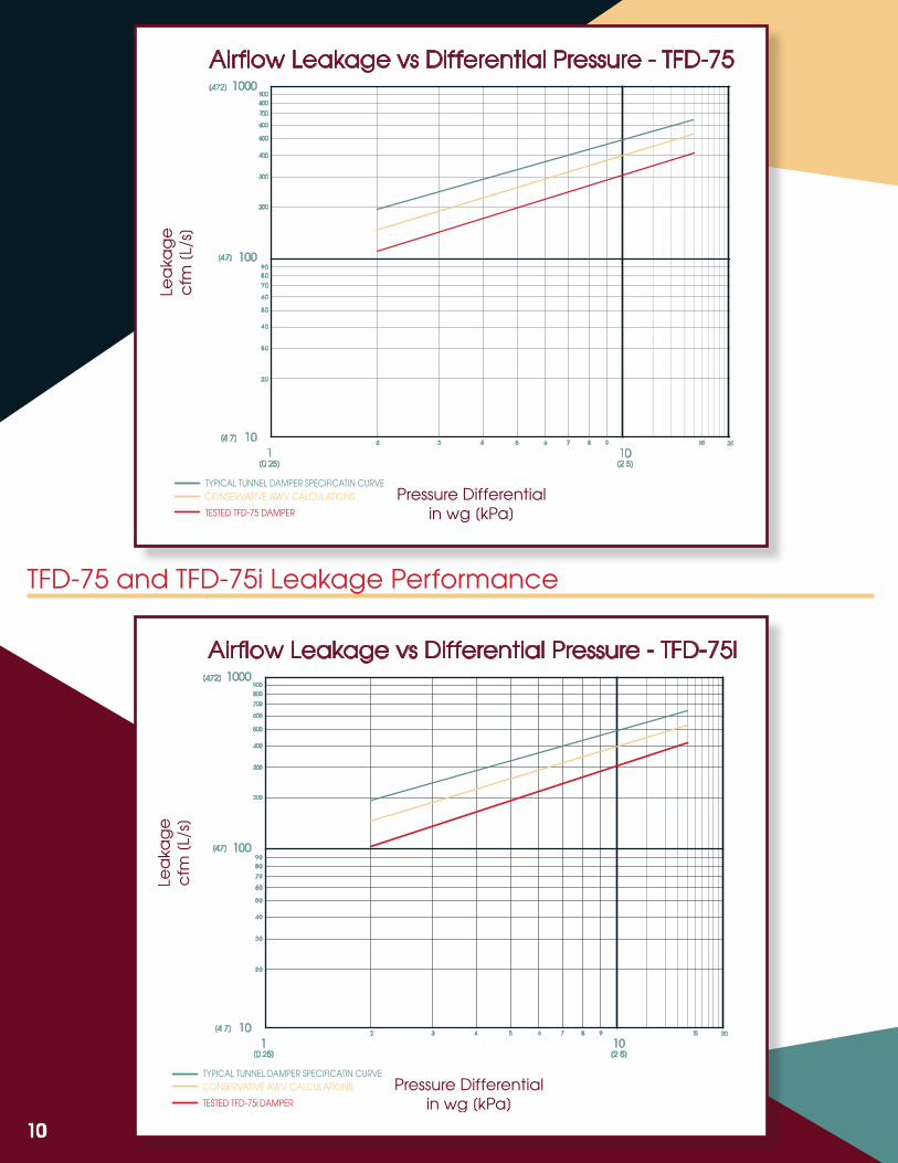
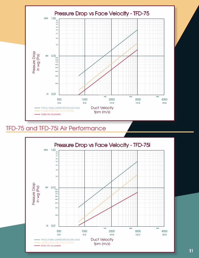
TFD-75 and TFD-75i Air Performance
12
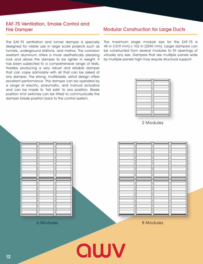
EAF-75 Ventilation, Smoke Control and Fire Damper
The EAF-75 ventilation and tunnel damper is specially designed for visible use in large scale projects such as tunnels, underground stations, and metros. The corrosion resistant aluminum offers a more aesthetically pleasing look and allows the damper to be lighter in weight. It has been subjected to a comprehensive range of tests, thereby producing a very robust and reliable damper that can cope admirably with all that can be asked of any damper. The strong, multiblade, airfoil design offers excellent performance. This damper can be operated by a range of electric, pneumatic, and manual actuators and can be made to ‘ fail safe’ to any position. Blade position limit switches can be fitted to communicate the damper blade position back to the control system.
2 Modules
6 Modules 8 Modules
Modular Construction for Large Ducts
The maximum single module size for the EAF-75 is 48 in [1219 mm] x 102 in [2590 mm]. Larger dampers can be constructed from several modules to fill openings of virtually any size. Dampers that are multiple panels wide by multiple panels high may require structural support.
13
EAF-75 Standard Specification
FRAME:
The 0.1875 in [4.76 mm] thick x 9.5 in [241.3 mm] x 3 in [76.2 mm] x 2 in [50.8 mm] deep extruded aluminum channel sections incorporates flanges drilled to meet client ’s requirements.
BLADES:
A minimum of 0.125 in [3.2 mm] thick extruded aluminum, double skin, airfoil cross section, parallel, or opposed action.
SHAFTS:
0.75 in [19 mm] round stub shafts are made of zinc-plated or stainless steel and are bolted to the blades to enable blade removal without extracting the whole damper from its operational mounting.
LINKAGE:
Zinc-plated steel or stainless steel linkage arms and interconnect bars, and stainless steel pivot pins with oil impregnated bronze pivot bearings.
BEARINGS:
Self-lubricating oil impregnated bronze sleeve bearings are pressed into the frame.
OPTIONS:
• Square shafts featuring heavy-duty oil impregnated bronze bearings that are housed in stainless steel casings. Linkage arms are bolted to the shafts. With this configuration the bearing and linkage arms are removable from outside the damper frame while the damper remains in service.
• Continuous shafts are also available.
• Blade and jamb seals can be fitted to further minimize the passage of air or smoke through the closed damper. Jamb seals are made from stainless steel while blade seals are made from silicone. UL555’s Class II leakage is standard for blade and jamb seals. Class I is available on request.
• Actuators can be double acting pneumatic, spring return pneumatic, double acting electric or spring return pneumatic, two position electric, or spring return electric. All have been successfully tested for operation at 482°F [250°C] for a one-hour duration. Some actuators have been tested up to four hours. Please contact AWV for your exact requirements.
• Limit switches provide an independent set of contacts to give positive damper position indication at the fully open and fully closed positions. Switches have been tested for operation at 482°F [250°C] for four hours.
• Screens made of galvanized or stainless steel provide a safeguard against debris and rubbish from entering and damaging the fans and sound attenuators in a ventilation system.
• Structural supports are recommended for dampers that are multiple panels wide by multiple panels high in order to maintain structural integrity against the dampers’ own weight and to resist distortion when installed. It is also recommended to minimize flexing when subjected to pulsating train-induced pressures.
• Mounting gaskets can be supplied made from solid silicone compound. These gaskets are good for 482°F [250°C] continuous temperature.
TESTING:
The EAF-75 damper has been heat tested to 482°F [250°C] for one hour in accordance with NFPA130.
The EAF-75 can be found in use on San Juan’s Tren Urbano transit system, and Atlanta’s MARTA transit system, along with many other locations.
14
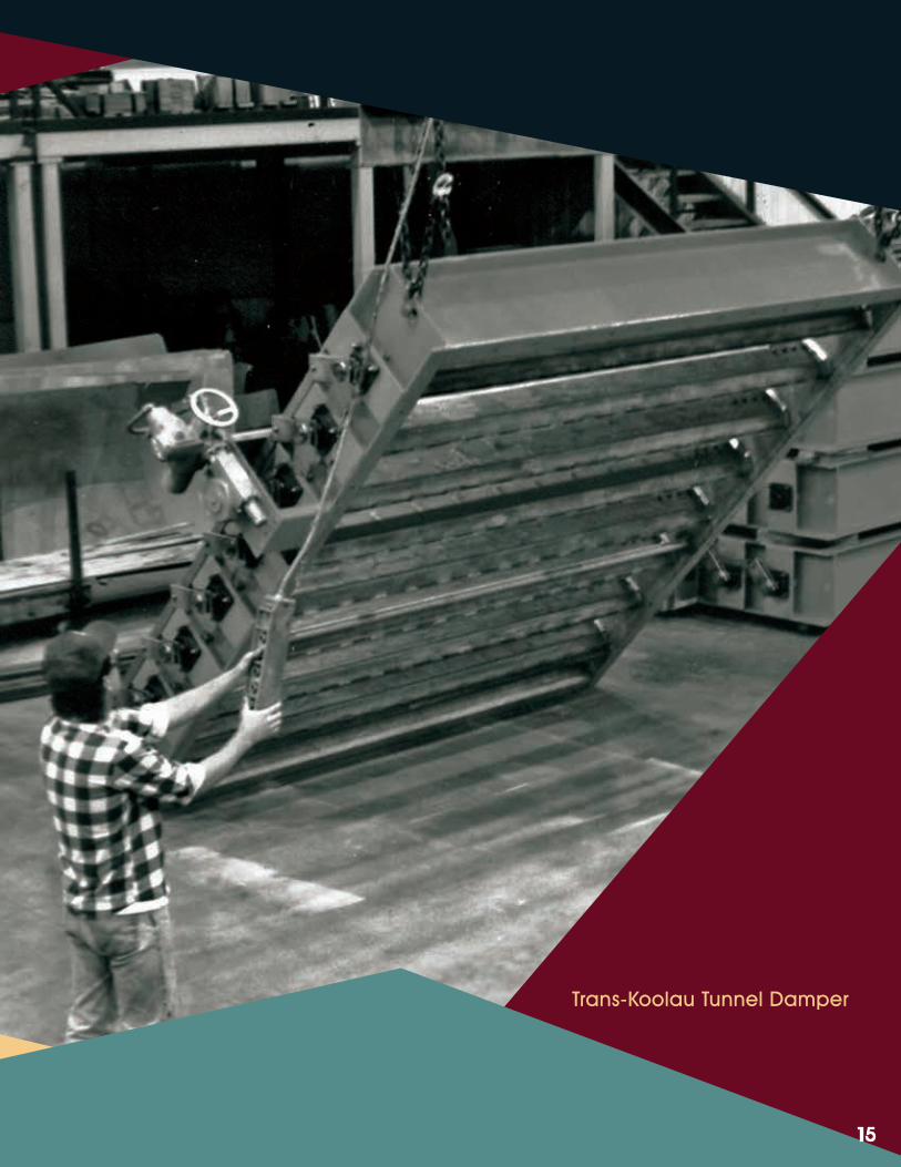
The VC-51 is currently in use at many locations such as Honolulu’s Trans-Koolau Tunnel (H-3 Interstate) in Hawaii, Virginia’s Hampton Roads Transit Tunnel, and Toronto’s Spadina Line Extension and Lawrence Station in Canada.
The VC-51 is our most customizable tunnel damper and because of its versatility, it is individually designed for each application. This model offers the largest single section panels available - typical designs can be as large as 13 ft [3.96 m] x 18 ft [5.48 m]. Rugged, heavy-duty linkage and ball bearings or cartridge sleeve bearings are a minimum. This damper can be constructed from a wide variety of materials, including 304 or 316 stainless steel, aluminum, etc. in a variety of thicknesses to meet the requirements of each project.
VC-51 Standard Specification
FRAME:
Typical designs can be up to 0.375 in [9.5 mm] thick x 20 in [508 mm] deep.
BLADES:
Designs may include up to 0.25 in [6.3 mm] thick skins for airfoil shape bolted or welded to the shaft. Various blade designs are available to offer the most economical design for each project.
SHAFTS:
Shafts up to 5 in [127 mm] can be designed. Full-length and stub shafts are available.
LINKAGE:
Typical designs include heavy-duty type, alloy-steel interconnect bars with stainless steel pivot pins.
BEARINGS:
Typically designs include relubricable ball or cartridge sleeve type bearings with double gland stuffing boxes.
VC-51 Ventilation, Smoke Control and Fire Damper
OPTIONS:
Individual options may vary greatly to meet design requirements. Common examples include:
• Materials ranging from aluminum to mild-steel, stainless steel, and specialty alloyed-steels.
• Blade and jamb seals are available to meet design requirements.
• Actuators can be manual, electric, or pneumatic to meet design requirements.
TESTING:
The VC-51 has been designed to withstand pressures up to 60 in. wg. [15 kPa], velocities up to 10,000 fpm [50 m/s], and temperatures up to 1800°F [982°C].
Please contact an AWV representative today for specific performance test data and to discuss how we can customize this damper for your project ’s specific requirements.
15
Trans-Koolau Tunnel Damper
16
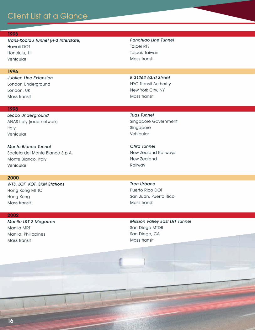
Client List at a Glance
1993Trans-Koolau Tunnel (H-3 Interstate)
Hawaii DOT
Honolulu, HI
Vehicular
1996Jubilee Line Extension
London Underground
London, UK
Mass transit
1998Lecco Underground
ANAS Italy (road network)
Italy
Vehicular
Monte Bianco Tunnel
Societa del Monte Bianco S.p.A.
Monte Bianco, Italy
Vehicular
2000WTS, LOF, KOT, SKM Stations
Hong Kong MTRC
Hong Kong
Mass transit
2002Manila LRT 2 Megatren
Manila MRT
Manila, Philippines
Mass transit
Panchiao Line Tunnel
Taipei RTS
Taipei, Taiwan
Mass transit
E-31262 63rd Street
NYC Transit Authority
New York City, NY
Mass transit
Tuas Tunnel
Singapore Government
Singapore
Vehicular
Otira Tunnel
New Zealand Railways
New Zealand
Railway
Tren Urbano
Puerto Rico DOT
San Juan, Puerto Rico
Mass transit
Mission Valley East LRT Tunnel
San Diego MTDB
San Diego, CA
Mass transit
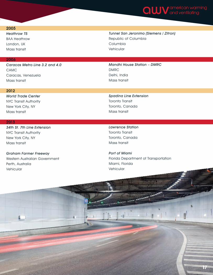
17
2005Heathrow T5
BAA Heathrow
London, UK
Mass transit
2006Caracas Metro Line 3.2 and 4.0
CAMC
Caracas, Venezuela
Mass transit
2012World Trade Center
NYC Transit Authority
New York City, NY
Mass transit
201334th St. 7th Line Extension
NYC Transit Authority
New York City, NY
Mass transit
Graham Farmer Freeway
Western Australian Government
Perth, Australia
Vehicular
Tunnel San Jeronimo (Siemens / Zitron)
Republic of Columbia
Columbia
Vehicular
Mandhi House Station – DMRC
DMRC
Delhi, India
Mass transit
Spadina Line Extension
Toronto Transit
Toronto, Canada
Mass transit
Lawrence Station
Toronto Transit
Toronto, Canada
Mass transit
Port of Miami
Florida Department of Transportation
Miami, Florida
Vehicular
18
19
A Mestek Company
AMCA MEMBER
American Warming and Ventilating, 7301 International Drive, Holland, Ohio 43528, USA
www.awv.com | Email: [email protected] | Phone: 419-865-5000 | Fax: 419-865-1375
facebook.com/AWV.USA @AmericanWarming
linkedin.com/company/american-warming-&-ventilating-a-mestek-company