Embed Size (px)
Citation preview

In-Plane Vibration Response of Piezoelectrically
Actuated Membranes
Umesh A. Korde∗, Eric A. Petersen†, Darwin Daugaard‡
South Dakota School of Mines and Technology, Rapid City, SD 57701, USA.
In this study, we investigate in-plane vibration response of membranes using piezo-electric actuation and sensing, with a view to understanding the effect of cracks or otherdefects on such response. We report on the analytical and experimental work on in-planevibration of a membrane strip actuated at one end and clamped at two ends. Tests arealso carried out with an artificially introduced defect, and the extensions of the theoreticaltreatment to model defects are discussed. In particular, some fundamental results from theliterature on the effect of defects on the natural response are discussed. Based in part onthese results, a Rayleigh-Ritz formulation is used to model the response without and withthe crack. Additional, ongoing studies on the in-plane impulse response of the membraneare reported. Finally, some experimental results are discussed for a membrane sheet withmultiple actuators and sensors.
I. Introduction
Potential applications for this work can be conceived for lightweight membrane space structures whichare difficult to access for inspection and monitoring of structural integrity. Integrated Vehicle Health
Monitoring Systems (IVHS) have been investigated1 on aircraft wings, helicopter rotors, etc.2 Recentlyreported research also includes health monitoring of lightweight composite panels.3 Work on characterizationof membranes using ultrasonic waves has been reported recently in the context of MEMS devices4.5 In thisstudy, we investigate in-plane vibration response of membrane strips and sheets using piezoelectric actuationand sensing, with a view to understanding the effect of cracks or other defects on such response. Dynamicsof membrane strips was studied analytically and experimentally by Hall et al.6 Wave propagation acrosssheets of paper has been studied by Hageger et al.7 For wave propagation studies mostly on thin sheetswhose dynamics are not influenced significantly by boundaries, Muktadi et al.8 have applied models basedon the theory of elasticity. In our previously reported studies on this topic, we focused exclusively onmembrane strips clamped at two ends and with a small amount of sag near the center. Oscillatory excitationwith a polyvinylidine fluoride (PVDF) actuator located at one end caused a modulation of the tension inthe membrane. This led to interesting temporal dynamics, with the evolution of each modal coefficientdescribed by the Mathieu equation.9 In this work, however, we investigate the dynamics of taut membraneswith no initial sag. The vibrations induced by the actuator are thus longitudinal, confined to the plane ofthe membrane, and need to be described by a different dynamic model, which is discussed here.
Here we report on the analytical and experimental work on in-plane vibration of a membrane stripactuated at one end and clamped at two ends, and a membrane sheet with multiple actuators/sensorsdistributed along its periphery and clamped or free along all edges. Tests are also carried out with anartificially introduced defect, and alternative extensions of the theoretical treatment to model defects arediscussed. The expected effect of a crack at the center span is discussed using variational-calculus-basedarguments, and in addition, a Rayleigh-Ritz type approximation is used to model the effect of a crack at thecenter-span. An alternative model accounting for the flexural stiffness and boundary-applied tension is used
∗Associate Professor, Department of Mechanical Engineering, South Dakota School of Mines and Technology, 501 East St.Joseph St., Rapid City, SD 57701.
†NSF REU Research Assistant, Currently at Department of Physics & Astronomy, University of Nebraska, Lincoln, NE68588.
‡NSF RET Research Assistant, Currently at Dell Rapids Public High School, 1214 North Garfield, Dell Rapids, SD 57022.
1 of 11
American Institute of Aeronautics and Astronautics
48th AIAA/ASME/ASCE/AHS/ASC Structures, Structural Dynamics, and Materials Conference<br> 15th23 - 26 April 2007, Honolulu, Hawaii
AIAA 2007-1745
Copyright © 2007 by the American Institute of Aeronautics and Astronautics, Inc. All rights reserved.

for thicker membranes, and the response at various points on a membrane strip to central impulsive loadingis calculated.
II. Unforced Response
The analysis in this section is focused on in-plane vibrations of a thin strip. Figure 1 shows a schematicfor the problem at hand. The treatment here is restricted to vibrations that are small enough to allow linearsuperposition to be applicable. This model is also restricted to long strips with lengths considerably greaterthat of the PVDF actuator strips. The effect of end clamps and PVDF strip mass and stiffness is ignoredfor now, and material damping is also neglected. In the case of the thin strip, excitation at one end that isuniform over the width will produce an internal particle displacement u(x, t) that, far-enough away from theends, is uniform over the width, besides being constant over the thickness. This motion will be described by
Figure 1. Schematic view of the membrane strip/actuator-sensor configuration considered here.
E∂2u
∂x2− ρ
∂2u
∂t2= f(x, t) (1)
with u(0, t) = u(L, t) = 0 at the two boundaries. The strip length, width, and thickness are taken to be L,B, and h respectively. E is the Young’s modulus of the strip material, in this case, Kapton. ρ denotes thematerial density, and f(x, t) is the external force per unit area per unit length in the x direction.
If we consider the natural response first, letting f(x, t) = 0,
c20
∂2u
∂x2− ∂2u
∂t2= 0 (2)
with c20 = E/ρ. A well-known separation of variables based solution approach leads to the general solution,
u(x, t) = (A sinβx + B cos βx)(C cos ωt + D sinωt) (3)
Application of the boundary conditions leads to,
sinβL = 0 ⇒ βn =nπ
L⇒ ωn = c0βn =
nπ
L
√E
ρ(4)
Thus, ωn is the n th natural frequency of axial vibrations of the strip as given by this approximate model,and U(x) = sin βnx is the n th mode shape.
The analysis needs to be modified significantly for the membrane sheet tests. In particular, because of therelatively large number of laminated PVDF actuator/sensor strips glued to the sheet, considerable flexuralrigidity is added to the membrane sheet. The current model is augmented in section III for a strip to accountfor the increased rigidity using a technique similar to that reported by Ruggiero,11 and extensions of thismodel to sheets will be discussed in future work.
2 of 11
American Institute of Aeronautics and Astronautics

A. Strip With Crack
The analysis for the membrane strip can also be extended to study the effect of a crack perpendicular to thelong sides. The effect of a crack at x = xa can be expressed as an additional line force at the crack locationgiven by,
Fc(x, t) =(
A
Ac− 1
)∂u
∂x(x, t)δ(xc) (5)
where A = Bh represents the cross section area of the strip, and Ai the intact area around the crack. Theequation of motion is then modified to,
∂
∂x
{EA
∂u
∂x+ EA
(A
Ac− 1
)∂u
∂x(x, t)δ(x− xc)
}− ρA
∂2u
∂t2= f(x, t) (6)
Evaluating the partial derivative for the second term in the bracket,
EA∂2u
∂x2+ EA
(A
Ac− 1
) [∂2u
∂x2δ(x− xc) +
∂u
∂xδ′(x− xc)
]− ρA
∂2u
∂t2= f(x, t) (7)
To solve this, we use the eigenfunctions of the intact membrane strip as comparison functions to obtain theapproximate natural frequencies and forced vibration response. Thus, we let
u(x, t) =M∑
n=1
ηn(t) sin(βnx) (8)
Substituting this into equation (7), letting the right side be zero for free vibration response, and using theorthogonality of the chosen comparison functions,
ρη̈n(t) + Eβ2nηn(t)−
N∑s=1
E
(1− Ai
A
)β2
sφs(xc)φn(xc)ηs(t) = 0 (9)
For the chosen number of comparison functions N , we can form mass and stiffness matrices [M ] and [K]from equation (9), and use these to compute the approximate natural frequencies ωnc of the cracked strip.
III. Alternative Approach to Crack Modeling
It can be shown using variational calculus based arguments12 that with a crack at mid-span, the fun-damental natural frequency must be less than or equal to the fundamental natural frequency without thecrack. This is because the crack allows eigenfunctions with a derivative discontinuity at the crack location, inaddition to the original eigenfunctions. The resulting increase in the size of the function space over which theeigenvalue minimization is performed enables an eigenvalue-eigenfunciton combination with a smaller eigen-value to be found. As shown below, this observation is reflected in the results based on the Rayleigh–Ritzapproximation below.
The Rayleigh–Ritz approximation approach below enables comparison functions to be used that satisfythe boundary conditions but have a derivative discontinuity. For a 3-term approximation under this approach,we choose the following functions:
φ1(x) = x2; φ2(x) = x3; φ3(x) = x4 (10)
for an intact strip, and for a strip with a crack at center-span,
φ1(x) = x2[H(x)−H(x− L/2)] + (L− x)2[H(x− L/2)−H(L)]
φ2(x) = x3[H(x)−H(x− L/2)] + (L− x)3[H(x− L/2)−H(L)]
φ3(x) = x3[H(x)−H(x− L/2)] + (L− x)3[H(x− L/2)−H(L)] (11)
where H(·) denotes the Heaviside step function. We represent the axial deformation in the two cases as
u(x, t) =3∑
i=1
qi(t)φi(x) ≡ {Φ(x)}T {q(t)} (12)
3 of 11
American Institute of Aeronautics and Astronautics

where {Φ(x)} and {q(t)} are vectors containing the elements φi and qi. The kinetic energy for the strip canthen be written as
T =12ρA
∫ L
0
{q̇}T {Φ}{Φ}T {q̇} =12{q̇}T [M ]{q̇} (13)
where
[M ] = ρA
∫ L
0
{Φ}{Φ}T dx
represents the mass matrix. Similarly, the potential energy can be expressed as
V =12ρA
∫ L
0
{q}T {Φ′}{Φ′}T {q̇} =12{q}T [K]{q} (14)
where
[K] = EA
∫ L
0
{Φ′}{Φ′}T dx
represents the stiffness matrix. Defining L = T − V , we have
d
dt
(∂L
∂{q̇}
)− ∂L
∂{q}= {0} (15)
This leads to the relation[M ]{q̈}+ [K]{q} = {0} (16)
The natural frequencies of this system can then be found by taking the square root of the eigenvalues of thematrix [M ]−1[K].
IV. Modified Formulation and Impulse Response
It is interesting to investigate the effect of flexural stiffness on the response of the strips and sheets beingconsidered here. Flexural stiffness becomes particularly important for the thicker membrane specimens(> 75µ m) used in some of the experiments. The vibrations produced by excitation of a particular actuatorthen are likely to contain an out-of-plane component that is influenced by both the flexural stiffness and theboundary-applied tension. In the following, we study the response of a strip with a finite flexural stiffnessand stretched between two end clamps. With an impulsive load applied at center-span, the non-laminatedPVDF transducers attached at the two ends here perform as sensors. In the model, the thickness and massof the transducers are taken to be negligible compared with the thickness and mass of the test specimenstrip. It is expected that a crack in the strip will alter the impulse response signatures measured by the twoend-mounted sensors, which will in turn enable the use of pulse-response signatures for characterization anddiagnosis of thicker membranes.
For small amplitude vibrations of a strip with finite flexural stiffness and boundary-applied tension perunit width τ , the out-of-plane deflection w(x, t) can be shown to be modeled according to
ρA∂2w
∂t2− τ
∂2w
∂x2+ Eh3 ∂4w
∂x4= −fr(x, t)− fa(x, t) (17)
where fr(x, t) and fa(x, t) respectively denote the forces caused by the damping and added mass of air. Forvibrations in vacuum, the strip admits the eigenfunction solutions,
φn(x) = sin βnx; βn =nπ
L(18)
Using these as comparison functions and assuming that the first N “modes” only are significant,
w(x, t) =N∑
n=1
ηn(t)φn(x) (19)
4 of 11
American Institute of Aeronautics and Astronautics

We expand the forces fr(x, t) and fa(x, t) as follows:
fr(x, t) =N∑
n=1
ρAcdnη̇n(t)φn(x)
fa(x, t) =N∑
n=1
ρAamnη̈n(t)φn(x) (20)
Furthermore, for the functions φn(x), we have
φ”n = −β2
nφn; and φ””n = β4
nφn (21)
Substituting equations (19), (20), and (21) into equation (17), multiplying both sides by a particular φn,integrating from 0 to L, and recognizing that φn are orthogonal, we have
η̈n(t) +cdn
1 + amnη̇n(t) +
Eh3β4n + τβ2
n
ρA(1 + amn)ηn(t) = 0 (22)
We have ηn(0) = 0, since w(x, 0) = 0. Here we consider an impulsive load applied by a swinging pendulumcomprised of a straight edge. If the “dynamic impulse” associated with this is denoted as F̃ and applied atx = ξ, then via application of the impulse momentum theorem, we can show that
η̇n(0+) =F̃
msφn(ξ) (23)
where 0+ denotes the instant just after impact, and ms = ρbhL is the mass of the strip. With η̇n(0+) asgiven by equation (23), the solution to equation (22) can be written as
ηn(t) =F̃ φn(ξ)msωnd
e−ζnωnt sinωndt (24)
where ωnd = ωn
√1− ζ2
n, ζn = cdn/2ωn(1 + amn), and
ωn =(
Eh3β4n + τβ2
n
ρA(1 + amn)
) 12
The overall response of the strip at chosen locations x = x̄ can then be computed using
w(x̄, t) =N∑
n=1
ηn(t)φn(x̄) (25)
In the results discussed below, we use F̃ = msg N-s.
V. Experimental Work
Two sets of experiments were carried out in this work. First, a rectangular, 25 µm thick Kapton stripwas stretched and held near its short edges between two structurally isolated clamps. A non-laminatedpolyvinylidine fluoride (PVDF) actuator spanning the entire strip width was firmly glued at one end, andan identical PVDF actuator was firmly glued at the other end to serve as a sensor (Figure 2). The Kaptonspecimen dimensions were 250 mm ×10 mm ×25 µm, and the actuator/sensor dimensions were 25 mm ×10mm ×58 µm. With no initial deformation in the Kapton strip, a harmonic (in time) voltage input appliedat the actuator causes a harmonic strain variation in the x(1) and y(2) directions as determined by the d31
coupling coefficient and the strength of the coupling provided by the adhesive. In the analysis above, thiscoupling was assumed to be perfect. It was not difficult to obtain the frequency response function (FRF) forthis set up using an arbitrary waveform generator to drive the actuator and a digital storage oscilloscope torecord the sensor output.
5 of 11
American Institute of Aeronautics and Astronautics

Figure 2. Photograph showing a Kapton strip mounted here with edges free, with a PVDF actuator/sensorat each end. x(1) axis is along the length, y(2) along the width, and z (3) is out of the plane of the strip.
Also tested was a 25 µm Kapton sheet with multiple actuator/sensor pairs. The sheet dimensions were200 mm ×100 mm ×25 µm. Laminated PVDF actuator/sensors of dimensions 15 mm ×10 mm ×58 µm wereused in this case. Four actuators each were glued along each of the two long sides, and Two along each of thetwo short sides (Figure 3. Tests were carried out both without and with the edges directly clamped. In theformer case, the stiffness provided by the actuator/sensor leads was exploited to grip the membrane at theactuator leads, leaving the actual membrane edges free. As a way to build a small-amplitude multiple-input–multiple-output (MIMO) transfer function, individual actuators were excited in turn and the correspondingoutput was recorded at each of the other PVDF actuator/sensors. The different frequency response functionsthus obtained could be compared with each other, and with analytical predictions. Additional measurements
Figure 3. Photograph showing a Kapton sheet undergoing tests. PVDF actuator/sensors are distributed overthe periphery. x(1) axis is along the length, y(2) along the width, and z (3) is out of the plane of the sheet.
were also made on the sheet with a “defect” introduced at the center to study its effect on the measuredfrequency response functions. In these tests, this defect consisted of another PVDF actuator, which could,as an added benefit, measure the response at the center.
With the sheet held horizontal and wrinkle-free, a number of different types of fine dust particles weresprinkled over the surface to help visualize the vibration modes. A membrane-type out-of-plane vibrationwould have caused the dust particles to collect near nodes and move away from antinodes of the membranemodes. In this case, however, the particles were observed not to vibrate or rearrange themselves. This
6 of 11
American Institute of Aeronautics and Astronautics

supported the inference that the excitation introduced in-plane vibrations in the form of longitudinal standingwaves, which could only be sensed by a strain sensor adhered firmly to the sheet. More experimental workon the mechanism of energy transfer over the sheet may be warranted, however.
VI. Discussion of Results
Figure 4 shows the corresponding experimental results. There seems to be a reasonable match at somefrequencies, although it appears that more precise experimental measurements are necessary. In particular,filtering techniques need to be investigated to eliminate noise at 60 Hz and its harmonics. Figure 5 comparesthe experimental results with a transverse crack about midspan of the strip. The crack appears to leadingto some additional peaks in the response, but the tallest peak (presumed due to the resonance for thePVDF actuator) is almost unchanged. Figure 6 plots the results from a test on the membrane sheet withone actuator active. As discussed above, the visualization tests performed by sprinkling fine particles on
Figure 4. The experimentally measured frequency response function values in the neighborhood of the theo-retically predicted peaks.
the membrane sheets provided a strong confirmation that the effect of the actuator was to set off in-planevibrations in the membrane. Based on the theoretical and experimental results, most of the interestingdynamics appears to be taking place in the ultrasonic frequency range. Additional tests were carried out onthe sheet to test the effect of boundaries. As part of these tests, the multiple-output–single-input frequencyresponse function was measured for excitation using a single actuator with the boundaries clamped. Thesemeasurements were next repeated with the sheet edges free. In this case, the sheet was supported in place byholding it at the actuator/sensor leads. The two sets of measurements were almost identical, which suggeststhat the influence of the boundaries on the dynamics seems to be minimal.
Due to the possibility of electromagnetic noise corrupting the experimental data and the smallness of theincident power, however, proper shielding techniques need to be implemented. Follow on experiments withthese improvements are in progress.
Calculations were carried out for the free axial vibration response of the strip, without and with the crack.As mentioned above, the analysis with the crack included modeling of the crack as line reduction in stiffness,with the associated inter-modal coupling. As Figure 7 shows, the predicted natural frequencies for thecracked strip are considerably different, as one would expect based on vibration theory. We would anticipatethat coupling between any two previously independent oscillation modes leads to coupled natural frequenciessuch that the lower coupled natural frequency is smaller than the lower uncoupled natural frequency, and thehigher coupled natural frequency is greater than the higher uncoupled natural frequency. In turn, this leadsto the prediction that, if individual oscillation modes could be identified in the experiments, one could seea considerable difference between the natural frequencies without and with the crack. While the analyticalresults conform to expectations in this regard, our experiments so far have not been as definitive. Figure
7 of 11
American Institute of Aeronautics and Astronautics

Figure 5. Experimental measurements of strip response without and with a transverse crack; Tests wereconducted for different orientations of the two membrane faces on either side of the crack.
Figure 6. Experimental measurements on the membrane sheet. The output of a sensor on one of the longeredges is measured with an actuator at the opposite edge is excited harmonically.
8 of 11
American Institute of Aeronautics and Astronautics

Figure 7. Natural frequencies for axial vibration of individual modes with and without crack.
8 shows the results based on the Rayleigh–Ritz approximation, which allows response approximations witha derivative discontinuity at the crack. In this case a crack was assumed at mid-span. Exact values foruncracked specimens from Figure 7 and approximate values for uncracked specimens based on the Rayleigh-Ritz approximation are plotted in this figure, and are found to match reasonably closely. For the crackedspecimen, the first natural frequency is found to be lower than that for the intact specimen. However, the2nd and 3rd are found to be greater. As mentioned previously, the comparison functions chosen here are notmutually orthogonal. Since only the comparison function for the first mode is allowed not to be orthogonalto the rest (based on the variational arguments above) the results for the first mode should bear out theprediction that the natural frequency with the crack will be lower than than without. This is seen to be thecase here.
Figures 9 plots the impulse response at various points on a thicker strip (> 75µ m) for an assumedvalue of damping. The oscillations are seen to be dominated by a frequency ∼ 520 Hz. This is very closeto the first damped natural frequency of 513 Hz. It is observed that for all levels of damping tested, theresponse near the ends (x = 12 mm, x = 282 mm) has a smaller magnitude than that close to the site of theimpact. This could be because the oscillations are dominated by the fundamental mode, and the functionφn(x) = sin(nπx/L) has small values near the ends.
Acknowledgements
This work is supported by the Air Force Research Laboratory, Space Vehicles Directorate (AFRL/VS),Kirtland AFB, NM. We are grateful to Dr. Jeffry Welsh and Mr. Jack Massarello of AFRL/VS for theirsupport. We are also grateful to the NSF Research Experience for Undergraduates program (# 0453216; PI:Dr. Lidvin Kjerengtroen) and the NSF Research Experience for Teachers program (PI: Dr. Robb Winter)for their support of Eric Petersen and Darwin Daugaard respectively.
References
1Lane RL, ‘Sensors and sensing technologies for integrated health monitoring systems’, The AMPTIAC Quarterly, v. 8,n. 3, 2004, pp. 11–15
2Tumer IY and Huff EM, ‘Analysis of triaxial vibration data for health monitoring of helicopter gearboxes ’, J. Vibrationand Acoustics, v. 122, 2003, pp. 120–128
3Yuan S, Lei W and Shi L, ‘Active monitoring for on-line damage detection in composite structures’, J. Vibration andAcoustics, v. 125, 2003, pp. 178–186
9 of 11
American Institute of Aeronautics and Astronautics
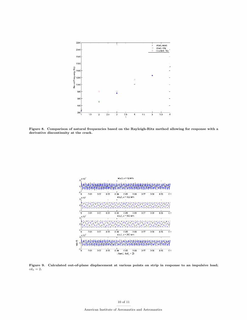
Figure 8. Comparison of natural frequencies based on the Rayleigh-Ritz method allowing for response with aderivative discontinuity at the crack.
Figure 9. Calculated out-of-plane displacement at various points on strip in response to an impulsive load;cdn = 2.
10 of 11
American Institute of Aeronautics and Astronautics

4Rufer L, Domingues C, and Mir S, ‘Behavior modeling and simulation of a MEMS-based ultrasonic pulse-echo system’,in Design, Test, Integration, and Packaging of MEMS/MOEMS, Courtois B, Karam JM, Markus KW, Michel B, MukherjeeT, Walker J (eds.), SPIE Proceedings, 2002, SPIE 0277-786
5Profusner DM, Vollmann J, and Dural J, ‘Mechanical Charagerization of thin membranes with picosecond ultra sound’,Microsystems Engineering: Metrology and Inspection III, C Gorecki (editor), Proc. SPIE Vol 5145, 2003, pp. 53–60
6Hall J, Glease RM, Flint E, ‘Dynamic behavior of this film membrane strips’, 43 rd AIAA/ASMEASCE/ASC Structures,Structural Dynamics,and Materials Conference, Denver, Co, 2002; AIAA 2000–1378
7Habeger CC, Mann RW, Baum, GA, ‘Ultrasonic plate waves in paper’, IPC Technical Paper Series, number 54, March1978.
8Mukdadi OM, Datta SK, Telschow KL, Deason VA, ‘Off-axis propagation of ultrasonic guided waves in thin orthotropiclayers: theoretical analysis and dynamic holographic imaging measurement’, IEEE Trans. Ultrasonics, Ferroelectrics, andFrequency Control, vol. 48, n. 6, November 2001, pp. 1581–1593.
9Korde UA, Jenkins CH, Petersen EA, ‘Effect of a crack on the response of a membrane strip to in-plane actuation’, in14 th AIAA/ASME/AHS Adaptive Structures Conference, Providence, RI, 2006; AIAA 2006–2224
10Auld BA,Acoustic Fields and Waves in Solids, Krieger Publishing Co., 2 nd ed., volume 1, 1990; Chapter 811Ruggiero EJ,Modeling and Control of SPIDER Satellite Components, PhD dissertation, Virginia Polytechnic Institute
and State University, July 2005; Chapter 612Weinstock R, Calculus of Variations: With Applications to Physics and Engineering, Dover Publications, New York,
1974 release of the McGraw–Hill ed, 1952, Chapter 9
11 of 11
American Institute of Aeronautics and Astronautics