Embed Size (px)
Citation preview
AIAA-2002-1457
1American Institute of Aeronautics and Astronautics
DESIGN OF A COLLAPSIBLE LIQUID OXYGEN
STORAGE VESSEL FOR MARS
David C. Fleming*
Florida Institute of Technology Melbourne, FL
Hisham E. Hegab†
Louisiana Tech University Ruston, LA
ABSTRACTFuture long-duration missions to Mars will require long term oxygen storage facilities. This report describes preliminary analysis of design concepts for lightweight, collapsible liquid oxygen storage tanks to be used on the surface of Mars. With storage at relatively low pressures an inflatable tank in which the cryogen is stored within a fiber-reinforced Teflon FEP bladder is an efficient approach. The weight of the proposed structure is dominated by the support structure needed to hold the tank off the ground and permit a vacuum insulation space to be maintained around the tank. Thermal aspects of the design are studied for various hardware configurations including tank arrangements, cryocoolers, and insulation concepts to minimize the initial launch mass to low Earth orbit. Results of the analyses indicate that high vacuum insulation systems will be required even though the temperature on the surface of Mars is much lower than Earth.
INTRODUCTIONPlans for future Mars missions propose using “in situ resource production” (ISRP) plants to obtain oxygen from the Martian atmosphere for use as a rocket propellant1. In the case of manned missions oxygen is also needed for life support. Particularly if an extended program of human missions to Mars is begun, it will be necessary to develop oxygen storage facilities on the surface of Mars. For launch from Earth, such storage tanks must obviously be lightweight. In addition, to improve the efficiency of the launch packaging the tank should be collapsible. This paper describes the preliminary analysis of design concepts for collapsible _________________ *Assistant Professor, Department of Mechanical & Aerospace Engineering, Member AIAA †Associate Professor, Department of Mechanical & Industrial Engineering, Member AIAA Copyright 2002 by the American Institute of Aeronautics and Astronautics, Inc. All rights reserved.
liquid oxygen storage tanks to be used on Mars. While no specific mission is followed for this design study, the capacity of the tank and other design requirements are based on the oxygen requirements for a manned Mars mission as described in the NASA Reference Mission1,2.
While there has been a substantial amount of research on ISRP, relatively little attention has been paid to storage requirements and tankage. The NASA Mars Reference mission1,2 assumes that produced oxygen will be fed directly into flight tanks on an ascent vehicle. Mueller and Durrant3 discuss storage issues for a proposed Mars sample return mission using this storage concept. However, if a prolonged series of Mars missions is begun, or for different mission architectures, it may be more efficient to provide long-term storage tanks on Mars separate from vehicle flight tanks.
PREVIOUS RESEARCHMars oxygen storage tanks will be substantially different from conventional terrestrial storage tanks or even ordinary flight tanks. However, previous engineering experience with collapsible pressure vessels, lightweight fluid storage tanks and inflatable space structures is relevant to the design of a collapsible cryogenic storage tank for Mars and is reviewed here. ILC Dover Inc.4 developed a collapsible hyperbaric chamber with an interior roughly the size of a person, designed for a burst pressure of 6 atm. The design uses a “bladder layer” of urethane-coated polyester to contain the gas with a “restraint layer” made of polyester webbing/polyester fabric to resist the mechanical loads. For mobile, lightweight storage of petroleum products the military uses collapsible bladder tanks. These tanks, made of fabric-reinforced elastomers, take the form of fluid-filled pillows and are available in capacities ranging up to the hundreds of thousands of gallons. Flanagan and Hopkins5 proposed a similar concept for water storage during human
43rd AIAA/ASME/ASCE/AHS/ASC Structures, Structural Dynamics, and Materials Con22-25 April 2002, Denver, Colorado
AIAA 2002-1457
Copyright © 2002 by the American Institute of Aeronautics and Astronautics, Inc. All rights reserved.
American Institute of Aeronautics and Astronautics 2
missions to the Moon or Mars. This tank is a simple bladder made of parachute nylon with a plastic liner. A prototype of such a 100 gallon capacity tank weighed about 1 kg (2.2 lbm). Inflatable space structures using similar principles for containing pressure have been developed or proposed for a variety of applications4,6.A recent development in inflatable space habitats is Transhab, developed at JSC and proposed for either long duration space flight or as a space station module2,4,7. Transhab uses triple redundant Kevlar reinforced membranes to form the main pressure barrier and a flexible outer layer for meteor impact protection and insulation. The net thickness of the wall is about one foot. Other inflatable structural concepts are described in Reference 7. An alternative to inflatables for collapsible space habitats and modules is telescoping rigid structures. Although this concept has not received as much attention as inflatables, a NASA design study8 proposed a two-stage telescoping arrangement space station module.
STRUCTURAL DESIGN Barron9 describes the fundamentals of the design of conventional cryogenic storage vessels. An inner vessel supports the weight of the cryogen and the associated pressure. To insulate the vessel either a vacuum space or vacuum-filled insulation is provided around the inner vessel. An outer pressure vessel contains the vacuum. A suspension system must be provided to hold the inner vessel within the outer vessel while minimizing the heat loss through the insulation space. Supports must be provided to hold the vessel. Finally, the necessary piping and fill lines must be included. Each of these basic tank components must be provided in the Mars liquid oxygen tank. Due to the mission requirements, however, the nature of these components may differ considerably from those of a conventional earth tank. Design requirements for a Mars liquid oxygen storage tank were chosen to provide a basis for evaluation. The tank must be capable of continuous operation for several Earth years and is sized to carry a mass of 50,000 kg (110,000 lbm) of liquid oxygen. The tank will hold a saturated liquid at 79 K (142 R) and 276 millibar (4 psia) ullage pressure. This pressure was selected primarily based upon the structural design of the collapsible tank. At this selected storage pressure, the corresponding saturation temperature of the liquid oxygen is approximately 79 K. Selecting a high storage pressure can increase the storage temperature to approximately 95 K, but this change was determined to produce little effect on the required insulation. For launch packaging it is assumed an inside diameter for the tank of nominally 10 ft (3m) will be acceptable.
Various concepts for the Mars LOX storage tank were considered including inflatable design concepts and telescoping structures. Two primary factors lead to the conclusion that an inflatable design will be more efficient: the low operating pressure and the requirements for high vacuum insulation. The pressure tank (“inner vessel”) will operate under the pressure of the oxygen vapor and the weight of the liquid oxygen. The head pressure of the liquid oxygen is 44.5 millibar per meter (0.197 psi per foot), considering the density at the operating temperature and the reduced gravity of Mars. For typical tank geometries the limit pressure is under 700 millibar (10 psi). For typical engineering materials the required wall thickness is therefore small, 1 mm (4 mils) or less. These small wall thicknesses are similar to those of flight tanks in early spacecraft, such as the pressure stabilized Atlas vehicle10. If the Mars storage tank is built to minimum dimensions it, too, must act as a pressure-stabilized structure, ineffective in supporting out-of-plane stresses that might be experienced while unpressurized. However, since considerable lateral loads may be anticipated during launch and landing it is likely that a rigid walled structure would require additional reinforcement. A flexible inflatable tank wall avoids this problem and can therefore be designed closer to its optimum weight. The second major driver of the design relates to the insulation of the tank. Although the Mars atmosphere exists in a condition that is categorized as “Medium Vacuum” 9, this level of vacuum is insufficient from an insulation standpoint (see Reference 3 and additional analysis below) and thus high vacuum must be drawn in the insulation space. A rigid vacuum vessel designed to resist even the relatively small atmospheric pressure of Mars would still be very heavy, considering the large dimensions of the tank. (If high vacuum were drawn in a rigid walled pressure vessel on Earth, the weight of the structure would be further increased by approximately a factor of six.) Therefore, a rigid pressure wall for the outer shell is not an efficient design. However, if an insulating material that can react either the full atmospheric pressure of Earth or the slight atmospheric pressure on Mars without damage or reduction in its thermal properties is used, then the outer wall may be made from a flexible material or a thin foil3. Not only is this approach very lightweight, it is also very well aligned with the objective of making a collapsible vessel. For these reasons, an inflatable tank concept appears most promising, and the following discussion will primarily discuss this configuration. However, some
American Institute of Aeronautics and Astronautics 3
discussion of design issues relating to alternate telescoping design concepts will also be presented.
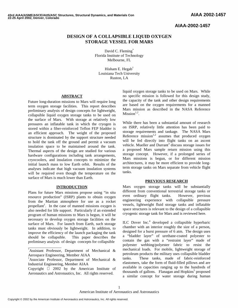
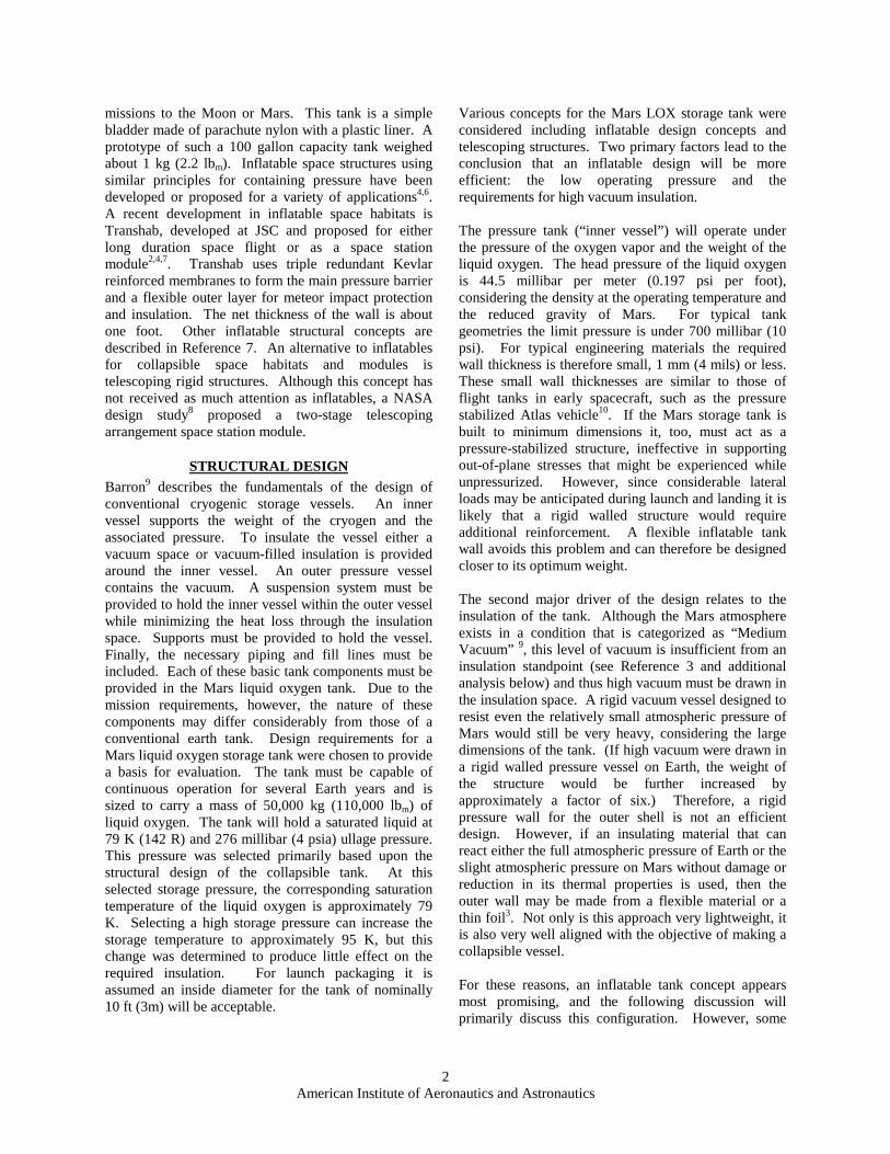
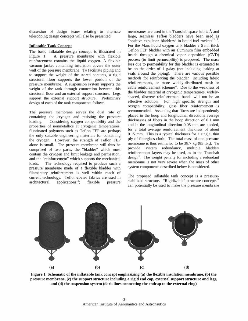
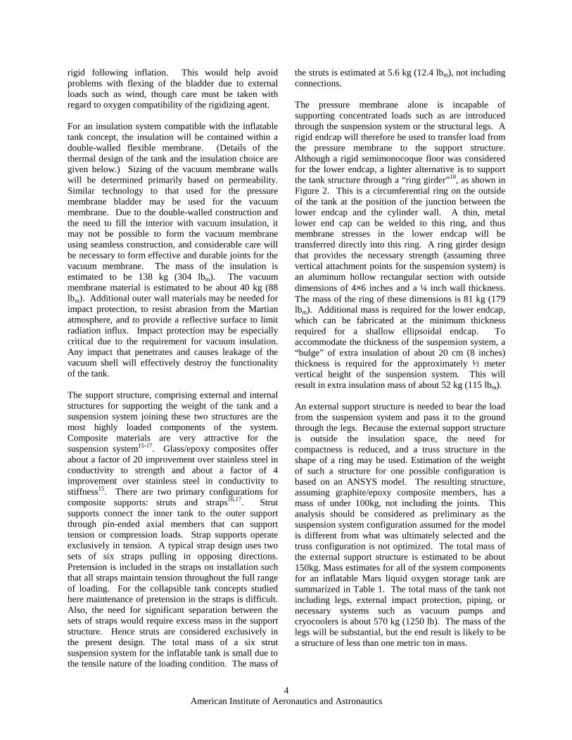
Inflatable Tank ConceptThe basic inflatable design concept is illustrated in Figure 1. A pressure membrane with flexible reinforcement contains the liquid oxygen. A flexible vacuum jacket containing insulation covers the outer wall of the pressure membrane. To facilitate piping and to support the weight of the stored contents, a rigid structural floor supports the lower portion of the pressure membrane. A suspension system supports the weight of the tank through connection between this structural floor and an external support structure. Legs support the external support structure. Preliminary design of each of the tank components follows. The pressure membrane serves the dual role of containing the cryogen and resisting the pressure loading. Considering oxygen compatibility and the properties of nonmetallics at cryogenic temperatures, fluorinated polymers such as Teflon FEP are perhaps the only suitable engineering materials for containing the cryogen. However, the strength of Teflon FEP alone is small. The pressure membrane will thus be comprised of two parts, the “bladder” which must contain the cryogen and limit leakage and permeation, and the “reinforcement” which supports the mechanical loads. The technology required to produce such a pressure membrane made of a flexible bladder with filamentary reinforcement is well within reach of current technology. Teflon-coated fabrics are used in architectural applications11; flexible pressure
membranes are used in the Transhab space habitat4; and large, seamless Teflon bladders have been used as “positive expulsion bladders” in liquid fuel rockets12,13.For the Mars liquid oxygen tank bladder a 6 mil thick Teflon FEP bladder with an aluminum film embedded inside through a chemical vapor deposition (CVD) process (to limit permeability) is proposed. The mass loss due to permeability for this bladder is estimated to be on the order of 1 g/day (not including leaking at seals around the piping). There are various possible methods for reinforcing the bladder including fabric reinforcements, or more widely-distributed mesh or cable reinforcement schemes4. Due to the weakness of the bladder material at cryogenic temperatures, widely-spaced, discrete reinforcement bands will not be an effective solution. For high specific strength and oxygen compatibility, glass fiber reinforcement is recommended. Assuming that fibers are independently placed in the hoop and longitudinal directions average thicknesses of fibers in the hoop direction of 0.1 mm and in the longitudinal direction 0.05 mm are needed, for a total average reinforcement thickness of about 0.15 mm. This is a typical thickness for a single, thin ply of fiberglass cloth. The total mass of one pressure membrane is thus estimated to be 38.7 kg (85 lbm). To provide system redundancy, multiple bladder/ reinforcement layers may be used, as in the Transhab design4. The weight penalty for including a redundant membrane is not very severe when the mass of other system components described below is considered. The proposed inflatable tank concept is a pressure-stabilized structure. “Rigidizable” structure concepts14 can potentially be used to make the pressure membrane
(a) (b) (c) (d)
Figure 1 Schematic of the inflatable tank concept emphasizing (a) the flexible insulation membrane, (b) the pressure membrane, (c) the support structure including a rigid end cap, external support structure and legs,
and (d) the suspension system (dark lines connecting the endcap to the external ring)
American Institute of Aeronautics and Astronautics 4
rigid following inflation. This would help avoid problems with flexing of the bladder due to external loads such as wind, though care must be taken with regard to oxygen compatibility of the rigidizing agent. For an insulation system compatible with the inflatable tank concept, the insulation will be contained within a double-walled flexible membrane. (Details of the thermal design of the tank and the insulation choice are given below.) Sizing of the vacuum membrane walls will be determined primarily based on permeability. Similar technology to that used for the pressure membrane bladder may be used for the vacuum membrane. Due to the double-walled construction and the need to fill the interior with vacuum insulation, it may not be possible to form the vacuum membrane using seamless construction, and considerable care will be necessary to form effective and durable joints for the vacuum membrane. The mass of the insulation is estimated to be 138 kg (304 lbm). The vacuum membrane material is estimated to be about 40 kg (88 lbm). Additional outer wall materials may be needed for impact protection, to resist abrasion from the Martian atmosphere, and to provide a reflective surface to limit radiation influx. Impact protection may be especially critical due to the requirement for vacuum insulation. Any impact that penetrates and causes leakage of the vacuum shell will effectively destroy the functionality of the tank. The support structure, comprising external and internal structures for supporting the weight of the tank and a suspension system joining these two structures are the most highly loaded components of the system. Composite materials are very attractive for the suspension system15-17. Glass/epoxy composites offer about a factor of 20 improvement over stainless steel in conductivity to strength and about a factor of 4 improvement over stainless steel in conductivity to stiffness15. There are two primary configurations for composite supports: struts and straps16,17. Strut supports connect the inner tank to the outer support through pin-ended axial members that can support tension or compression loads. Strap supports operate exclusively in tension. A typical strap design uses two sets of six straps pulling in opposing directions. Pretension is included in the straps on installation such that all straps maintain tension throughout the full range of loading. For the collapsible tank concepts studied here maintenance of pretension in the straps is difficult. Also, the need for significant separation between the sets of straps would require excess mass in the support structure. Hence struts are considered exclusively in the present design. The total mass of a six strut suspension system for the inflatable tank is small due to the tensile nature of the loading condition. The mass of
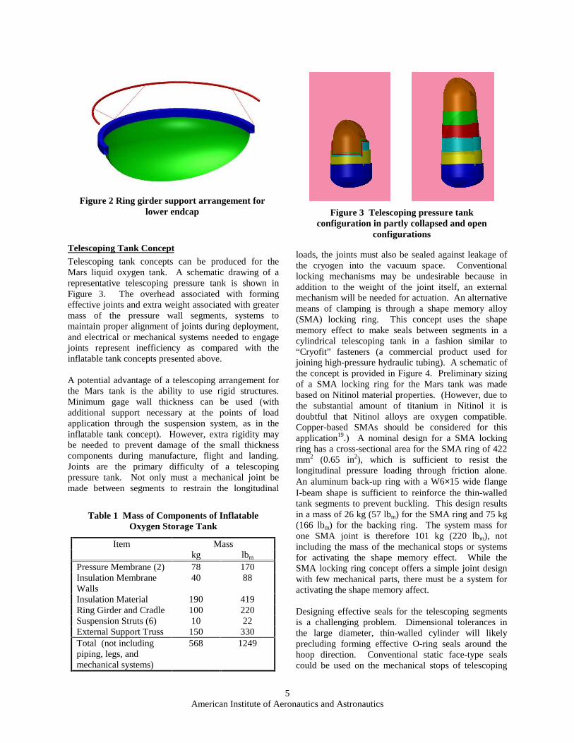
the struts is estimated at 5.6 kg (12.4 lbm), not including connections. The pressure membrane alone is incapable of supporting concentrated loads such as are introduced through the suspension system or the structural legs. A rigid endcap will therefore be used to transfer load from the pressure membrane to the support structure. Although a rigid semimonocoque floor was considered for the lower endcap, a lighter alternative is to support the tank structure through a “ring girder”18, as shown in Figure 2. This is a circumferential ring on the outside of the tank at the position of the junction between the lower endcap and the cylinder wall. A thin, metal lower end cap can be welded to this ring, and thus membrane stresses in the lower endcap will be transferred directly into this ring. A ring girder design that provides the necessary strength (assuming three vertical attachment points for the suspension system) is an aluminum hollow rectangular section with outside dimensions of 4×6 inches and a ¼ inch wall thickness. The mass of the ring of these dimensions is 81 kg (179 lbm). Additional mass is required for the lower endcap, which can be fabricated at the minimum thickness required for a shallow ellipsoidal endcap. To accommodate the thickness of the suspension system, a “bulge” of extra insulation of about 20 cm (8 inches) thickness is required for the approximately ½ meter vertical height of the suspension system. This will result in extra insulation mass of about 52 kg (115 lbm). An external support structure is needed to bear the load from the suspension system and pass it to the ground through the legs. Because the external support structure is outside the insulation space, the need for compactness is reduced, and a truss structure in the shape of a ring may be used. Estimation of the weight of such a structure for one possible configuration is based on an ANSYS model. The resulting structure, assuming graphite/epoxy composite members, has a mass of under 100kg, not including the joints. This analysis should be considered as preliminary as the suspension system configuration assumed for the model is different from what was ultimately selected and the truss configuration is not optimized. The total mass of the external support structure is estimated to be about 150kg. Mass estimates for all of the system components for an inflatable Mars liquid oxygen storage tank are summarized in Table 1. The total mass of the tank not including legs, external impact protection, piping, or necessary systems such as vacuum pumps and cryocoolers is about 570 kg (1250 lb). The mass of the legs will be substantial, but the end result is likely to be a structure of less than one metric ton in mass.
American Institute of Aeronautics and Astronautics 5
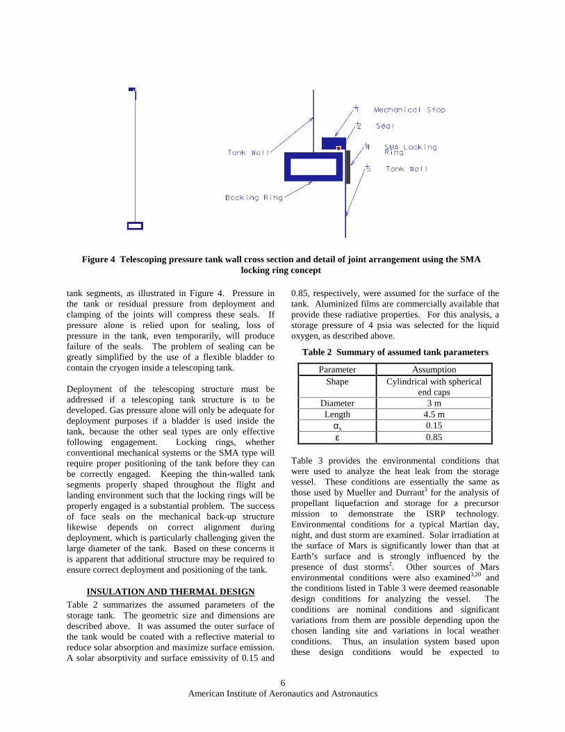
Telescoping Tank ConceptTelescoping tank concepts can be produced for the Mars liquid oxygen tank. A schematic drawing of a representative telescoping pressure tank is shown in Figure 3. The overhead associated with forming effective joints and extra weight associated with greater mass of the pressure wall segments, systems to maintain proper alignment of joints during deployment, and electrical or mechanical systems needed to engage joints represent inefficiency as compared with the inflatable tank concepts presented above. A potential advantage of a telescoping arrangement for the Mars tank is the ability to use rigid structures. Minimum gage wall thickness can be used (with additional support necessary at the points of load application through the suspension system, as in the inflatable tank concept). However, extra rigidity may be needed to prevent damage of the small thickness components during manufacture, flight and landing. Joints are the primary difficulty of a telescoping pressure tank. Not only must a mechanical joint be made between segments to restrain the longitudinal
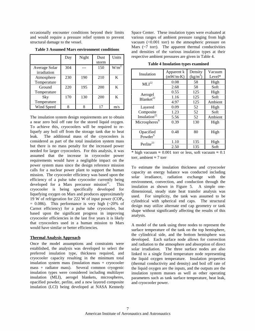
loads, the joints must also be sealed against leakage of the cryogen into the vacuum space. Conventional locking mechanisms may be undesirable because in addition to the weight of the joint itself, an external mechanism will be needed for actuation. An alternative means of clamping is through a shape memory alloy (SMA) locking ring. This concept uses the shape memory effect to make seals between segments in a cylindrical telescoping tank in a fashion similar to “Cryofit” fasteners (a commercial product used for joining high-pressure hydraulic tubing). A schematic of the concept is provided in Figure 4. Preliminary sizing of a SMA locking ring for the Mars tank was made based on Nitinol material properties. (However, due to the substantial amount of titanium in Nitinol it is doubtful that Nitinol alloys are oxygen compatible. Copper-based SMAs should be considered for this application19.) A nominal design for a SMA locking ring has a cross-sectional area for the SMA ring of 422 mm2 (0.65 in2), which is sufficient to resist the longitudinal pressure loading through friction alone. An aluminum back-up ring with a W6×15 wide flange I-beam shape is sufficient to reinforce the thin-walled tank segments to prevent buckling. This design results in a mass of 26 kg (57 lbm) for the SMA ring and 75 kg (166 lbm) for the backing ring. The system mass for one SMA joint is therefore 101 kg (220 lbm), not including the mass of the mechanical stops or systems for activating the shape memory effect. While the SMA locking ring concept offers a simple joint design with few mechanical parts, there must be a system for activating the shape memory affect. Designing effective seals for the telescoping segments is a challenging problem. Dimensional tolerances in the large diameter, thin-walled cylinder will likely precluding forming effective O-ring seals around the hoop direction. Conventional static face-type seals could be used on the mechanical stops of telescoping
Figure 2 Ring girder support arrangement for lower endcap
Table 1 Mass of Components of Inflatable Oxygen Storage Tank
Mass Item kg lbm
Pressure Membrane (2) 78 170 Insulation Membrane Walls
40 88
Insulation Material 190 419 Ring Girder and Cradle 100 220 Suspension Struts (6) 10 22 External Support Truss 150 330 Total (not including piping, legs, and mechanical systems)
568 1249
Figure 3 Telescoping pressure tank configuration in partly collapsed and open
configurations
American Institute of Aeronautics and Astronautics 6
tank segments, as illustrated in Figure 4. Pressure in the tank or residual pressure from deployment and clamping of the joints will compress these seals. If pressure alone is relied upon for sealing, loss of pressure in the tank, even temporarily, will produce failure of the seals. The problem of sealing can be greatly simplified by the use of a flexible bladder to contain the cryogen inside a telescoping tank. Deployment of the telescoping structure must be addressed if a telescoping tank structure is to be developed. Gas pressure alone will only be adequate for deployment purposes if a bladder is used inside the tank, because the other seal types are only effective following engagement. Locking rings, whether conventional mechanical systems or the SMA type will require proper positioning of the tank before they can be correctly engaged. Keeping the thin-walled tank segments properly shaped throughout the flight and landing environment such that the locking rings will be properly engaged is a substantial problem. The success of face seals on the mechanical back-up structure likewise depends on correct alignment during deployment, which is particularly challenging given the large diameter of the tank. Based on these concerns it is apparent that additional structure may be required to ensure correct deployment and positioning of the tank.
INSULATION AND THERMAL DESIGN Table 2 summarizes the assumed parameters of the storage tank. The geometric size and dimensions are described above. It was assumed the outer surface of the tank would be coated with a reflective material to reduce solar absorption and maximize surface emission. A solar absorptivity and surface emissivity of 0.15 and
0.85, respectively, were assumed for the surface of the tank. Aluminized films are commercially available that provide these radiative properties. For this analysis, a storage pressure of 4 psia was selected for the liquid oxygen, as described above.
Table 2 Summary of assumed tank parameters
Parameter Assumption Shape Cylindrical with spherical
end caps Diameter 3 m Length 4.5 m
αs 0.15 ε 0.85
Table 3 provides the environmental conditions that were used to analyze the heat leak from the storage vessel. These conditions are essentially the same as those used by Mueller and Durrant3 for the analysis of propellant liquefaction and storage for a precursor mission to demonstrate the ISRP technology. Environmental conditions for a typical Martian day, night, and dust storm are examined. Solar irradiation at the surface of Mars is significantly lower than that at Earth’s surface and is strongly influenced by the presence of dust storms2. Other sources of Mars environmental conditions were also examined3,20 and the conditions listed in Table 3 were deemed reasonable design conditions for analyzing the vessel. The conditions are nominal conditions and significant variations from them are possible depending upon the chosen landing site and variations in local weather conditions. Thus, an insulation system based upon these design conditions would be expected to
Figure 4 Telescoping pressure tank wall cross section and detail of joint arrangement using the SMA locking ring concept
American Institute of Aeronautics and Astronautics 7
occasionally encounter conditions beyond their limits and would require a pressure relief system to prevent structural damage to the vessel.
Table 3 Assumed Mars environment conditions
Day Night Dust storm
Units
Average Solar irradiation
304 --- 150 W/m2
Atmosphere Temperature
230 190 210 K
Ground Temperature
220 195 200 K
Sky Temperature
170 130 200 K
Wind Speed 8 8 17 m/s
The insulation system design requirements are to obtain a near zero boil off rate for the stored liquid oxygen. To achieve this, cryocoolers will be required to re-liquefy any boil off from the storage tank due to heat leak. The additional mass of the cryocoolers is considered as part of the total insulation system mass but there is no mass penalty for the increased power needed for larger cryocoolers. For this analysis, it was assumed that the increase in cryocooler power requirements would have a negligible impact on the power system mass since the design reference mission calls for a nuclear power plant to support the human mission. The cryocooler efficiency was based upon the efficiency of a pulse tube cryocooler currently being developed for a Mars precursor mission21. This cryocooler is being specifically developed for liquefying oxygen on Mars and produces approximately 19 W of refrigeration for 222 W of input power (COPR
= 0.086). This performance is very high (~20% of Carnot efficiency) for a pulse tube cryocooler, but based upon the significant progress in improving cryocooler efficiencies in the last five years it is likely that cryocoolers used in a human mission to Mars would have similar or better efficiencies.
Thermal Analysis ApproachOnce the model assumptions and constraints were established, the analysis was developed to select the preferred insulation type, thickness required, and cryocooler capacity resulting in the minimum total insulation system mass (insulation mass + cryocooler mass + radiator mass). Several common cryogenic insulation types were considered including multilayer insulation (MLI), aerogel blankets, microspheres, opacified powder, perlite, and a new layered composite insulation (LCI) being developed at NASA Kennedy
Space Center. These insulation types were evaluated at various ranges of ambient pressure ranging from high vacuum (<0.001 torr) to the atmospheric pressure on Mars (~7 torr). The apparent thermal conductivities and densities of the various insulation types at their respective ambient pressures are given in Table 4.
Table 4 Insulation types examined
Insulation Apparent k (mW/m-K)
Density (kg/m3)
Vacuum Level*
0.08 58 High MLI22 2.68 58 Soft 0.55 125 High 1.16 125 Soft
Aerogel Blanket22
4.97 125 Ambient 0.09 52 High 1.23 52 Soft
Layered Composite Insulation22 5.56 52 Ambient
Microspheres9 0.39 130 High
Opacified Powder9
0.48 80 High
1.10 135 High Perlite23
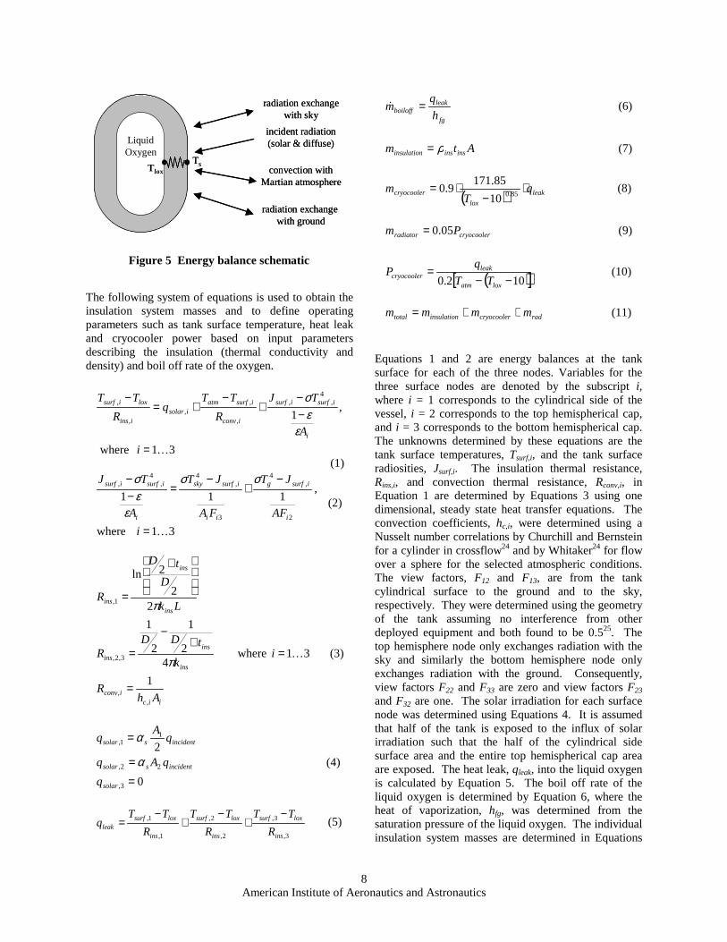
2.50 135 Soft * high vacuum ≈ 0.001 torr or less, soft vacuum ≈ 0.1 torr, ambient ≈ 7 torr To estimate the insulation thickness and cryocooler capacity an energy balance was conducted including solar irradiance, radiation exchange with the environment, convection, and conduction through the insulation as shown in Figure 5. A simple one-dimensional, steady state heat transfer analysis was used. For simplicity, the tank was assumed to be cylindrical with spherical end caps. The structural design may utilize alternate end cap geometry or tank shape without significantly affecting the results of this analysis. A model of the tank using three nodes to represent the surface temperature of the tank on the top hemisphere, the cylindrical side, and the bottom hemisphere was developed. Each surface node allows for convection and radiation to the atmosphere and absorption of direct solar irradiation. The three surface nodes are also linked to a single fixed temperature node representing the liquid oxygen temperature. Insulation properties (thermal conductivity and density) and boil off rate of the liquid oxygen are the inputs, and the outputs are the insulation system masses as well as other operating parameters such as tank surface temperature, heat leak, and cryocooler power.
American Institute of Aeronautics and Astronautics 8
The following system of equations is used to obtain the insulation system masses and to define operating parameters such as tank surface temperature, heat leak and cryocooler power based on input parameters describing the insulation (thermal conductivity and density) and boil off rate of the oxygen.
Equations 1 and 2 are energy balances at the tank surface for each of the three nodes. Variables for the three surface nodes are denoted by the subscript i,where i = 1 corresponds to the cylindrical side of the vessel, i = 2 corresponds to the top hemispherical cap, and i = 3 corresponds to the bottom hemispherical cap. The unknowns determined by these equations are the tank surface temperatures, Tsurf,i, and the tank surface radiosities, Jsurf,i. The insulation thermal resistance, Rins,i, and convection thermal resistance, Rconv,i, in Equation 1 are determined by Equations 3 using one dimensional, steady state heat transfer equations. The convection coefficients, hc,i, were determined using a Nusselt number correlations by Churchill and Bernstein for a cylinder in crossflow24 and by Whitaker24 for flow over a sphere for the selected atmospheric conditions. The view factors, F12 and F13, are from the tank cylindrical surface to the ground and to the sky, respectively. They were determined using the geometry of the tank assuming no interference from other deployed equipment and both found to be 0.525. The top hemisphere node only exchanges radiation with the sky and similarly the bottom hemisphere node only exchanges radiation with the ground. Consequently, view factors F22 and F33 are zero and view factors F23 and F32 are one. The solar irradiation for each surface node was determined using Equations 4. It is assumed that half of the tank is exposed to the influx of solar irradiation such that the half of the cylindrical side surface area and the entire top hemispherical cap area are exposed. The heat leak, qleak, into the liquid oxygen is calculated by Equation 5. The boil off rate of the liquid oxygen is determined by Equation 6, where the heat of vaporization, hfg, was determined from the saturation pressure of the liquid oxygen. The individual insulation system masses are determined in Equations
fg
leakboiloff h
qm =& (6)
Atm insinsinsulation ρ= (7)
( ) leak
lox
cryocooler qT
m ⋅−
⋅=85.010
85.1719.0 (8)
cryocoolerradiator Pm 05.0= (9)
( )[ ]102.0 −−=
loxatm
leakcryocooler TT
qP (10)
radcryocoolerinsulationtotal mmmm ++= (11)
LiquidOxygen
incident radiation(solar & diffuse)
convection withMartian atmosphere
radiation exchange with ground
radiation exchangewith sky
TsTlox
LiquidOxygen
incident radiation(solar & diffuse)
convection withMartian atmosphere
radiation exchange with ground
radiation exchangewith sky
TsTlox
Figure 5 Energy balance schematic
31 where
,1
4,,
,
,,
,
,
K=
−−
+−
+=−
i
A
TJ
R
TTq
R
TT
i
isurfisurf
iconv
isurfatmisolar
iins
loxisurf
εεσ
(1)
31where
,111
2
,4
3
,44
,,
K=
−+
−=
−−
i
AF
JT
FA
JT
A
TJ
i
isurfg
ii
isurfsky
i
isurfisurf σσ
εεσ
(2)
1
31where4
2
1
2
1
22
2ln
,,
3,2,
1,
iiciconv
ins
ins
ins
ins
ins
ins
AhR
ik
tDDR
Lk
D
tD
R
=
=+
−
=
+
=
Kπ
π
(3)
0
2
3,
22,
11,
==
=
solar
incidentssolar
incidentssolar
q
qAq
qA
q
α
α
(4)
3,
3,
2,
2,
1,
1,
ins
loxsurf
ins
loxsurf
ins
loxsurfleak R
TT
R
TT
R
TTq
−+
−+
−= (5)
American Institute of Aeronautics and Astronautics 9
7-9. Equation 8 is an empirical correlation developed by Kittel et al26 that predicts cryocooler mass based upon commercially available cryocoolers. Equation 9 is another empirical correlation that predicts the required radiator mass for the cryocooler3. Equation 10 is used to estimate the cryocooler power assuming that it has a 20% Carnot efficiency21. Finally, the total insulation system mass is determined by Equation11.
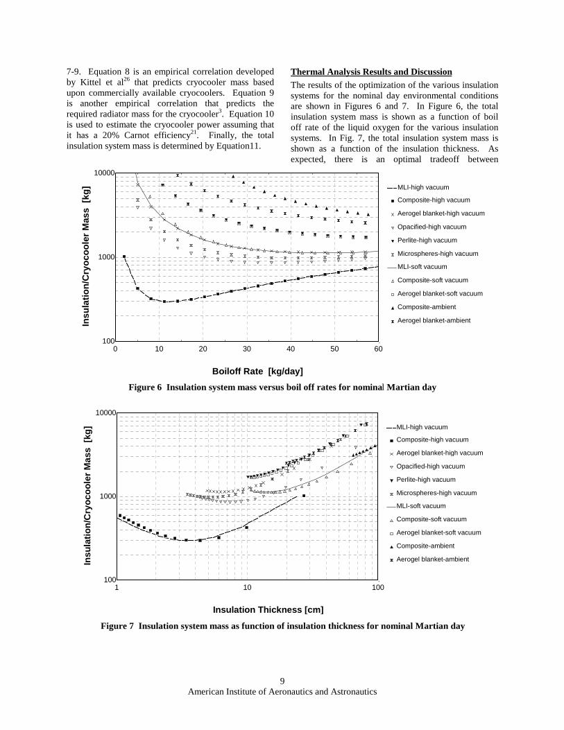
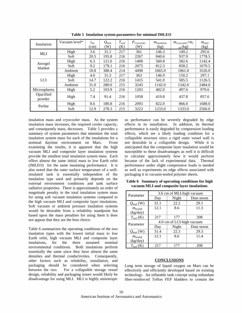
Thermal Analysis Results and DiscussionThe results of the optimization of the various insulation systems for the nominal day environmental conditions are shown in Figures 6 and 7. In Figure 6, the total insulation system mass is shown as a function of boil off rate of the liquid oxygen for the various insulation systems. In Fig. 7, the total insulation system mass is shown as a function of the insulation thickness. As expected, there is an optimal tradeoff between
0 10 20 30 40 50 60100
1000
10000
Boiloff Rate [kg/day]
Insu
lati
on
/Cry
oco
ole
rM
ass
[kg
] MLI-high vacuum
MLI-soft vacuum
Aerogel blanket-ambient
Aerogel blanket-soft vacuum
Microspheres-high vacuum
Composite-ambient
Aerogel blanket-high vacuum
Composite-soft vacuum
Composite-high vacuum
Opacified-high vacuum
Perlite-high vacuum
Figure 6 Insulation system mass versus boil off rates for nominal Martian day
1 10 100100
1000
10000
Insulation Thickness [cm]
Insu
lati
on
/Cry
oco
ole
rM
ass
[kg
] MLI-high vacuum
MLI-soft vacuum
Aerogel blanket-ambient
Aerogel blanket-soft vacuum
Microspheres-high vacuum
Composite-ambient
Aerogel blanket-high vacuum
Composite-soft vacuum
Composite-high vacuum
Opacified-high vacuum
Perlite-high vacuum
Figure 7 Insulation system mass as function of insulation thickness for nominal Martian day
American Institute of Aeronautics and Astronautics 10
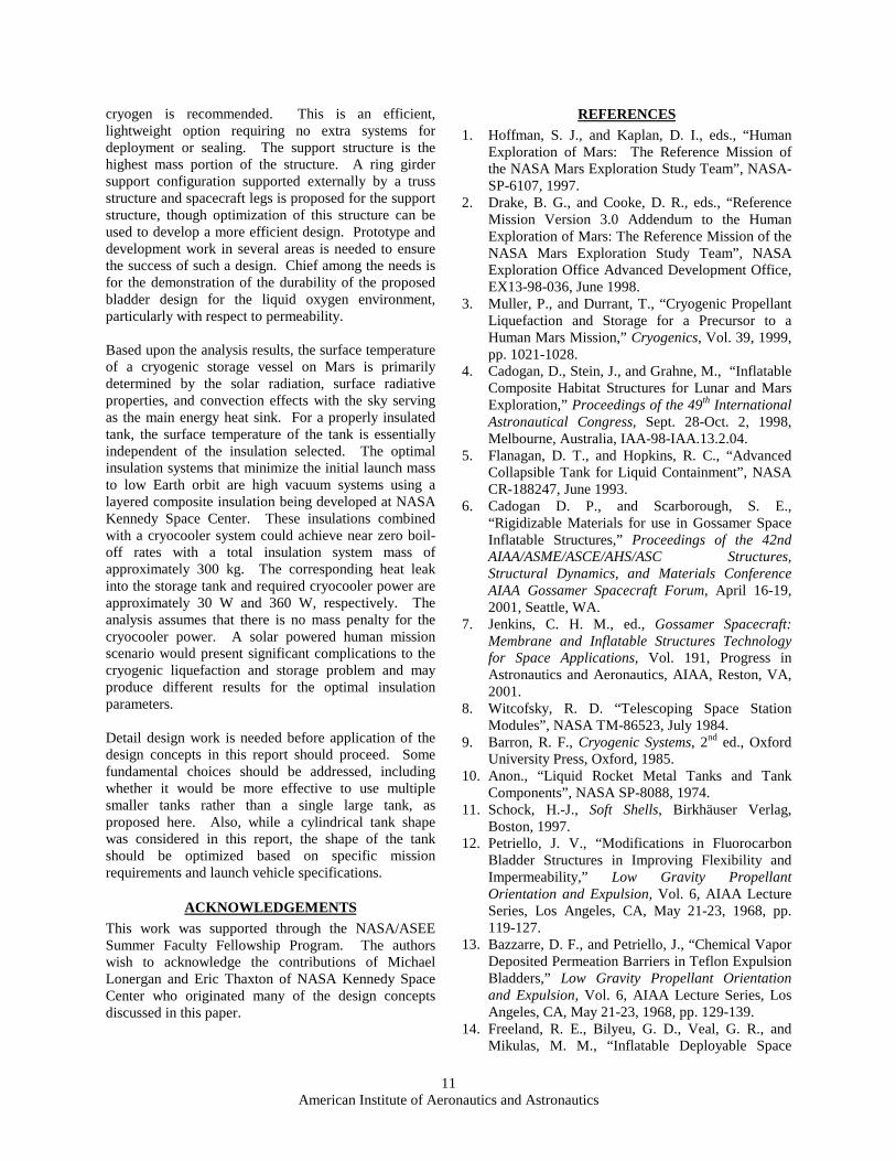
insulation mass and cryocooler mass. As the system insulation mass increases, the required cooler capacity, and consequently mass, decreases. Table 5 provides a summary of system parameters that minimize the total insulation system mass for each of the insulations for a nominal daytime environment on Mars. From examining the results, it is apparent that the high vacuum MLI and composite layer insulation systems provide the smallest total insulation system mass. Each offers almost the same initial mass to low Earth orbit (IMLEO) for the same insulating performance. It is also noted that the outer surface temperature of a well-insulated tank is essentially independent of the insulation type used and primarily depends on the external environment conditions and tank surface radiative properties. There is approximately an order of magnitude penalty in the total insulation system mass for using soft vacuum insulation systems compared to the high vacuum MLI and composite layer insulations. Soft vacuum or ambient pressure insulation systems would be desirable from a reliability standpoint but based upon the mass penalties for using them it does not appear that they are the best choice. Table 6 summarizes the operating conditions of the two insulation types with the lowest initial mass to low Earth orbit, high vacuum MLI and composite layer insulations, for the three assumed nominal environmental conditions. Both insulations perform essentially the same since they have almost the same densities and thermal conductivities. Consequently, other factors such as reliability, installation, and packaging should be considered when selecting between the two. For a collapsible storage vessel design, reliability and packaging issues would likely be disadvantage for using MLI. MLI is highly anisotropic
so performance can be severely degraded by edge effects in its installation. In addition, its thermal performance is easily degraded by compression loading effects, which are a likely loading condition for a collapsible structure since a rigid outer vessel wall is not desirable in a collapsible design. While it is anticipated that the composite layer insulation would be susceptible to these disadvantages as well it is difficult to calculate approximately how it would perform because of the lack of experimental data. Thermal performance under slight compressive loads is needed as well as experiments on edge effects associated with packaging it in vacuum-sealed polymer sheets.
Table 6 Summary of operating conditions for high vacuum MLI and composite layer insulations
3.6 cm of MLI-high vacuum Parameter Day Night Dust storm
Qleak (W) 31.1 22.2 29.1 mboiloff
(kg/day) 12.1 8.6 11.3
Tsurf (K) 217 177 208 4.0 cm of LCI-high vacuum
Parameter Day Night Dust storm
Qleak (W) 31.4 22.3 29.3 mboiloff
(kg/day) 12.1 8.6 11.4
Tsurf (K) 217 177 208
CONCLUSIONSLong term storage of liquid oxygen on Mars can be effectively and efficiently developed based on existing technology. An inflatable tank concept using redundant fiber-reinforced Teflon FEP bladders to contain the
Table 5 Insulation system parameters for minimal IMLEO
Insulation Vacuum level* tins
(cm) Qleak
(W) Tsurf
(K) Pcryocooler
(W) minsulation
(kg) mcryocooler+mr
ad (kg) mtotal
(kg) High 3.6 31.1 217 361 146.3 149.2 295.6 MLI Soft 20.5 195.8 216 2267 840.6 937.9 1778.5 High 6.3 121.6 216 1408 560.8 582.6 1142.4 Soft 9.2 179.1 216 2075 812.3 858.2 1670.5
Aerogel blanket
Ambient 18.8 388.4 214 4498 1665.0 1861.0 3526.0 High 4.0 31.3 217 363 146.9 150.2 297.1 Soft 14.7 122.2 216 1415 541.0 585.5 1126.5 LCI
Ambient 31.0 280.0 215 3243 1142.0 1342.0 2484.0 Microspheres High 5.2 103.9 216 1203 482.0 497.6 979.6
Opacified powder
High 7.4 91.4 216 1058 419.8 437.8 857.6
High 8.6 180.8 216 2093 822.0 866.0 1688.0 Perlite
Soft 12.9 278.3 215 3223 1233.0 1333.0 2566.0
American Institute of Aeronautics and Astronautics 11
cryogen is recommended. This is an efficient, lightweight option requiring no extra systems for deployment or sealing. The support structure is the highest mass portion of the structure. A ring girder support configuration supported externally by a truss structure and spacecraft legs is proposed for the support structure, though optimization of this structure can be used to develop a more efficient design. Prototype and development work in several areas is needed to ensure the success of such a design. Chief among the needs is for the demonstration of the durability of the proposed bladder design for the liquid oxygen environment, particularly with respect to permeability. Based upon the analysis results, the surface temperature of a cryogenic storage vessel on Mars is primarily determined by the solar radiation, surface radiative properties, and convection effects with the sky serving as the main energy heat sink. For a properly insulated tank, the surface temperature of the tank is essentially independent of the insulation selected. The optimal insulation systems that minimize the initial launch mass to low Earth orbit are high vacuum systems using a layered composite insulation being developed at NASA Kennedy Space Center. These insulations combined with a cryocooler system could achieve near zero boil-off rates with a total insulation system mass of approximately 300 kg. The corresponding heat leak into the storage tank and required cryocooler power are approximately 30 W and 360 W, respectively. The analysis assumes that there is no mass penalty for the cryocooler power. A solar powered human mission scenario would present significant complications to the cryogenic liquefaction and storage problem and may produce different results for the optimal insulation parameters. Detail design work is needed before application of the design concepts in this report should proceed. Some fundamental choices should be addressed, including whether it would be more effective to use multiple smaller tanks rather than a single large tank, as proposed here. Also, while a cylindrical tank shape was considered in this report, the shape of the tank should be optimized based on specific mission requirements and launch vehicle specifications.
ACKNOWLEDGEMENTSThis work was supported through the NASA/ASEE Summer Faculty Fellowship Program. The authors wish to acknowledge the contributions of Michael Lonergan and Eric Thaxton of NASA Kennedy Space Center who originated many of the design concepts discussed in this paper.
REFERENCES1. Hoffman, S. J., and Kaplan, D. I., eds., “Human
Exploration of Mars: The Reference Mission of the NASA Mars Exploration Study Team”, NASA-SP-6107, 1997.
2. Drake, B. G., and Cooke, D. R., eds., “Reference Mission Version 3.0 Addendum to the Human Exploration of Mars: The Reference Mission of the NASA Mars Exploration Study Team”, NASA Exploration Office Advanced Development Office, EX13-98-036, June 1998.
3. Muller, P., and Durrant, T., “Cryogenic Propellant Liquefaction and Storage for a Precursor to a Human Mars Mission,” Cryogenics, Vol. 39, 1999, pp. 1021-1028.
4. Cadogan, D., Stein, J., and Grahne, M., “Inflatable Composite Habitat Structures for Lunar and Mars Exploration,” Proceedings of the 49th International Astronautical Congress, Sept. 28-Oct. 2, 1998, Melbourne, Australia, IAA-98-IAA.13.2.04.
5. Flanagan, D. T., and Hopkins, R. C., “Advanced Collapsible Tank for Liquid Containment”, NASA CR-188247, June 1993.
6. Cadogan D. P., and Scarborough, S. E., “Rigidizable Materials for use in Gossamer Space Inflatable Structures,” Proceedings of the 42nd AIAA/ASME/ASCE/AHS/ASC Structures, Structural Dynamics, and Materials Conference AIAA Gossamer Spacecraft Forum, April 16-19, 2001, Seattle, WA.
7. Jenkins, C. H. M., ed., Gossamer Spacecraft: Membrane and Inflatable Structures Technology for Space Applications, Vol. 191, Progress in Astronautics and Aeronautics, AIAA, Reston, VA, 2001.
8. Witcofsky, R. D. “Telescoping Space Station Modules”, NASA TM-86523, July 1984.
9. Barron, R. F., Cryogenic Systems, 2nd ed., Oxford University Press, Oxford, 1985.
10. Anon., “Liquid Rocket Metal Tanks and Tank Components”, NASA SP-8088, 1974.
11. Schock, H.-J., Soft Shells, Birkhäuser Verlag, Boston, 1997.
12. Petriello, J. V., “Modifications in Fluorocarbon Bladder Structures in Improving Flexibility and Impermeability,” Low Gravity Propellant Orientation and Expulsion, Vol. 6, AIAA Lecture Series, Los Angeles, CA, May 21-23, 1968, pp. 119-127.
13. Bazzarre, D. F., and Petriello, J., “Chemical Vapor Deposited Permeation Barriers in Teflon Expulsion Bladders,” Low Gravity Propellant Orientation and Expulsion, Vol. 6, AIAA Lecture Series, Los Angeles, CA, May 21-23, 1968, pp. 129-139.
14. Freeland, R. E., Bilyeu, G. D., Veal, G. R., and Mikulas, M. M., “Inflatable Deployable Space
American Institute of Aeronautics and Astronautics 12
Structures Technology Summary,” IAF-98-1.5.01, 1998.
15. Flynn, T. M., Cryogenic Engineering, Marcel Dekker, Inc., New York, 1997.
16. Kittel, P., “Comparison of Dewar supports for space applications,” Cryogenics, Vol. 33(4), 1993, pp. 429-434.
17. Reed, R. P., and Golda, M., “Cryogenic composite supports: a review of strap and strut properties,” Cryogenics, Vol. 37(5), 1997, pp. 233-250.
18. Moss, D. R., Pressure Vessel Design Manual, Gulf Publishing Co., Houston, 1987.
19. Janocha, H., ed., Adaptronics and Smart Structures, Springer, Berlin, 1999.
20. Anon., “Environment of Mars”, NASA-TM 100470, October 1988.
21. Marquardt, E. D., and Radebaugh, R., “Pulse Tube Oxygen Liquefier”, Adv. Cryogenic Engineering,Vol. 45, 2000, pp. 457-464.
22. Augustynowicz, S. D., and Fesmire, J. E., “Cryogenic Insulation System for Soft Vacuum.” KSC-00408 Report, 1999, pp. 1-7.
23. Barron, R. F., Cryogenic Heat Transfer, Taylor & Francis, Philadelphia, 1999, pp. 29-33.
24. Incropera, F. P. and DeWitt, D. P., Introduction to Heat Transfer, 3rd Ed., John Wiley & Sons, New York, 1996, p. 345-349.
25. Rea, S. N., “Rapid Method for Determining Concentric Cylinder Radiation View Factors”, AIAA Journal, Vol. 13, No. 8, August 1975, pp. 1122-1123.
26. Kittel, P., Salerno, L. J., and Plachta, D.W., “Cryocoolers for Human and Robotic Missions to Mars”, Cryocoolers 10, Kluwer Academic/Plenum Publishers, 1999, pp. 815-821.