Embed Size (px)
Citation preview
Amerex Owner’s Manual AMGaDS III Plus
Amerex Two Zone Mobile Gas Detection System Includes test procedure required for California vehicles and
“exemption letter”
ENP-116 Rev. B March 2016
Methane Detector Operation Manual
ENP-116: Amerex Owner’s Manual – AMGaDS III Plus Two Zone Mobile Gas Detection System 2
Proprietary Statement The information provided within this manual is proprietary and confidential. All prior versions of this manual, including updates and revisions forwarded separately, are proprietary. The information provided by Agility Fuel Systems to its customers and clients is solely for the use of those customers and clients. No portion of this manual may be reproduced or distributed without express written consent from Agility Fuel Systems. The methane gas detection owner’s manual included in this document is a publication of the Amerex Corporation, and is used with permission. Copies of the original manual are available from distributors of Amerex products. Attached: Amerex Owner’s Manual, Part Number 16531, AMGaDS III Plus, Two-Zone Mobile Gas Detection System, January 2003. This document includes notes from the Amerex 20188 AMGaDS III Calibration Kit. Check with your authorized Amerex dealer for the latest information.
1. Notes for California Vehicles Only Liquefied natural gas (LNG) fuel system vehicles in California must comply with CA Code of Regulations (13 CCR Section 935 (b) (2)), which requires the following:
• Every motor vehicle equipped with an LNG fuel system shall be equipped with a methane gas detection system which shall warn of the presence of methane in the engine compartment, driver's compartment and any passenger compartments.
• At a minimum, the methane gas detection system shall provide a warning before the methane gas concentration reaches 25% of the Lower Flammability Limit. Such warning shall be plainly audible and visible to the driver before entering the driver's compartment and while seated in the normal driving position.
• The gas detection system shall function continuously at all times, whether or not the engine is operating, when the vehicle is operated or parked on public roadways or other areas open to the public.
• At a minimum, the gas detection system shall be tested three times per calendar year at equal intervals. The testing procedure shall simulate the same gaseous fuel and operating environment in which the vehicle is used.
• Test results, validating the performance of the gas detection system within the parameters established by the component manufacturer(s), shall be maintained as a permanent part of the vehicle service history records.
In addition to the above, the California Highway Patrol will be adopting a requirement for the testing of two stages of flammability warning, the first at a range of 20 percent to 30 percent and the second stage at a range of 50 percent and 60 percent. A letter explaining these requirements is attached at the end of
Methane Detector Operation Manual
ENP-116: Amerex Owner’s Manual – AMGaDS III Plus Two Zone Mobile Gas Detection System 3
this document. A copy of the letter is to be carried in the vehicle and a copy is to be kept on file with the vehicle maintenance records. The letter must be presented to any inspecting officer if requested.
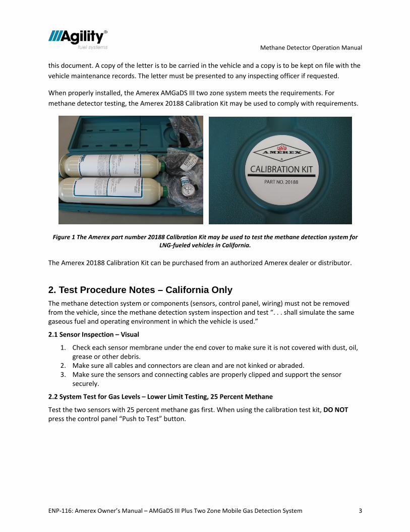
When properly installed, the Amerex AMGaDS III two zone system meets the requirements. For methane detector testing, the Amerex 20188 Calibration Kit may be used to comply with requirements.
Figure 1 The Amerex part number 20188 Calibration Kit may be used to test the methane detection system for LNG-fueled vehicles in California.
The Amerex 20188 Calibration Kit can be purchased from an authorized Amerex dealer or distributor.
2. Test Procedure Notes – California Only The methane detection system or components (sensors, control panel, wiring) must not be removed from the vehicle, since the methane detection system inspection and test “. . . shall simulate the same gaseous fuel and operating environment in which the vehicle is used.”
2.1 Sensor Inspection – Visual
1. Check each sensor membrane under the end cover to make sure it is not covered with dust, oil, grease or other debris.
2. Make sure all cables and connectors are clean and are not kinked or abraded. 3. Make sure the sensors and connecting cables are properly clipped and support the sensor
securely.
2.2 System Test for Gas Levels – Lower Limit Testing, 25 Percent Methane
Test the two sensors with 25 percent methane gas first. When using the calibration test kit, DO NOT press the control panel “Push to Test” button.
Methane Detector Operation Manual
ENP-116: Amerex Owner’s Manual – AMGaDS III Plus Two Zone Mobile Gas Detection System 4
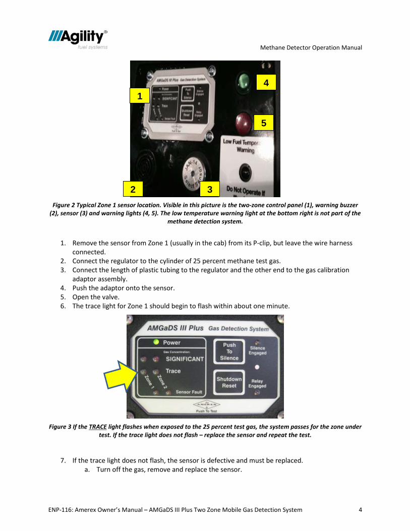
Figure 2 Typical Zone 1 sensor location. Visible in this picture is the two-zone control panel (1), warning buzzer
(2), sensor (3) and warning lights (4, 5). The low temperature warning light at the bottom right is not part of the methane detection system.
1. Remove the sensor from Zone 1 (usually in the cab) from its P-clip, but leave the wire harness connected.
2. Connect the regulator to the cylinder of 25 percent methane test gas. 3. Connect the length of plastic tubing to the regulator and the other end to the gas calibration
adaptor assembly. 4. Push the adaptor onto the sensor. 5. Open the valve. 6. The trace light for Zone 1 should begin to flash within about one minute.
Figure 3 If the TRACE light flashes when exposed to the 25 percent test gas, the system passes for the zone under
test. If the trace light does not flash – replace the sensor and repeat the test.
7. If the trace light does not flash, the sensor is defective and must be replaced. a. Turn off the gas, remove and replace the sensor.
1
2 3
4
5
Methane Detector Operation Manual
ENP-116: Amerex Owner’s Manual – AMGaDS III Plus Two Zone Mobile Gas Detection System 5
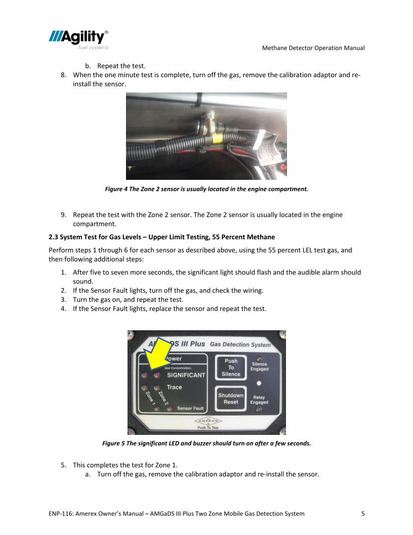
b. Repeat the test. 8. When the one minute test is complete, turn off the gas, remove the calibration adaptor and re-
install the sensor.
Figure 4 The Zone 2 sensor is usually located in the engine compartment.
9. Repeat the test with the Zone 2 sensor. The Zone 2 sensor is usually located in the engine compartment.
2.3 System Test for Gas Levels – Upper Limit Testing, 55 Percent Methane
Perform steps 1 through 6 for each sensor as described above, using the 55 percent LEL test gas, and then following additional steps:
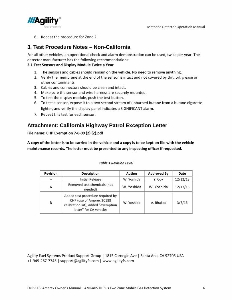
1. After five to seven more seconds, the significant light should flash and the audible alarm should sound.
2. If the Sensor Fault lights, turn off the gas, and check the wiring. 3. Turn the gas on, and repeat the test. 4. If the Sensor Fault lights, replace the sensor and repeat the test.
Figure 5 The significant LED and buzzer should turn on after a few seconds.
5. This completes the test for Zone 1. a. Turn off the gas, remove the calibration adaptor and re-install the sensor.
Methane Detector Operation Manual
ENP-116: Amerex Owner’s Manual – AMGaDS III Plus Two Zone Mobile Gas Detection System 6
6. Repeat the procedure for Zone 2.
3. Test Procedure Notes – Non-California For all other vehicles, an operational check and alarm demonstration can be used, twice per year. The detector manufacturer has the following recommendations: 3.1 Test Sensors and Display Module Twice a Year
1. The sensors and cables should remain on the vehicle. No need to remove anything. 2. Verify the membrane at the end of the sensor is intact and not covered by dirt, oil, grease or
other contaminants. 3. Cables and connectors should be clean and intact. 4. Make sure the sensor and wire harness are securely mounted. 5. To test the display module, push the test button. 6. To test a sensor, expose it to a two second stream of unburned butane from a butane cigarette
lighter, and verify the display panel indicates a SIGNIFICANT alarm. 7. Repeat this test for each sensor.
Attachment: California Highway Patrol Exception Letter File name: CHP Exemption 7-6-09 (2) (2).pdf
A copy of the letter is to be carried in the vehicle and a copy is to be kept on file with the vehicle maintenance records. The letter must be presented to any inspecting officer if requested.
Table 1 Revision Level
Revision Description Author Approved By Date
-- Initial Release W. Yoshida Y. Coy 12/12/13
A Removed test chemicals (not needed) W. Yoshida W. Yoshida 12/17/15
B
Added test procedure required by CHP (use of Amerex 20188
calibration kit); added “exemption letter” for CA vehicles
W. Yoshida A. Bhakta 3/7/16
Agility Fuel Systems Product Support Group | 1815 Carnegie Ave | Santa Ana, CA 92705 USA +1-949-267-7745 | [email protected] | www.agilityfs.com
Part Number 16531 January 2003 Page 1
OWNER’S MANUAL P/N 16531
AMGaDS III Plus
Amerex Two Zone Mobile Gas Detection System
Manufactured by: AMEREX Corporation
P. O. Box 81 Trussville, AL 35173-0081
Phone: (205) 655-3271 fax: (205) 655-3279
E-Mail: [email protected] Home Page: http://www.amerex-fire.com
Printed in USA January 2003
DocuSign Envelope ID: 2D362897-D937-4C72-93CB-6258A2931A42
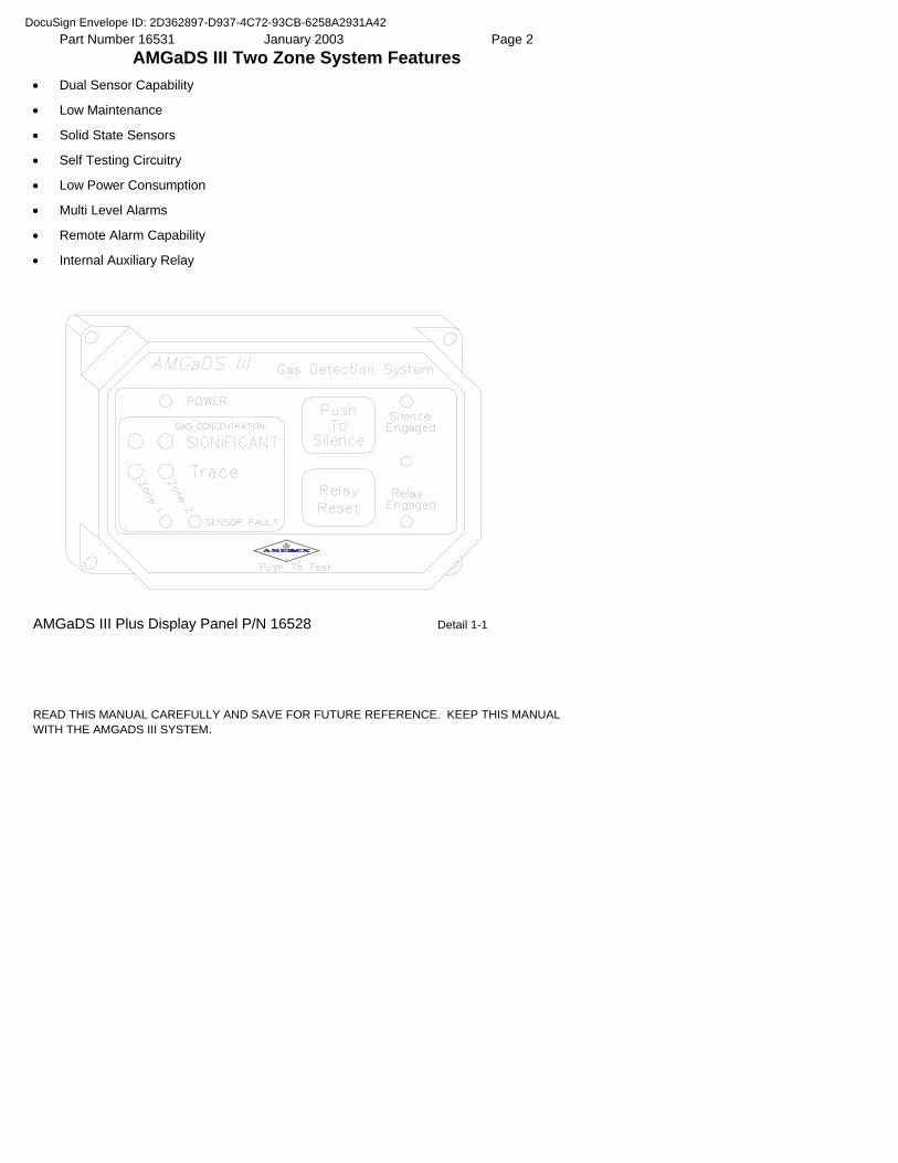
Part Number 16531 January 2003 Page 2 AMGaDS III Two Zone System Features
• Dual Sensor Capability
• Low Maintenance
• Solid State Sensors
• Self Testing Circuitry
• Low Power Consumption
• Multi Level Alarms
• Remote Alarm Capability
• Internal Auxiliary Relay
AMGaDS III Plus Display Panel P/N 16528 Detail 1-1
READ THIS MANUAL CAREFULLY AND SAVE FOR FUTURE REFERENCE. KEEP THIS MANUAL WITH THE AMGADS III SYSTEM.
DocuSign Envelope ID: 2D362897-D937-4C72-93CB-6258A2931A42
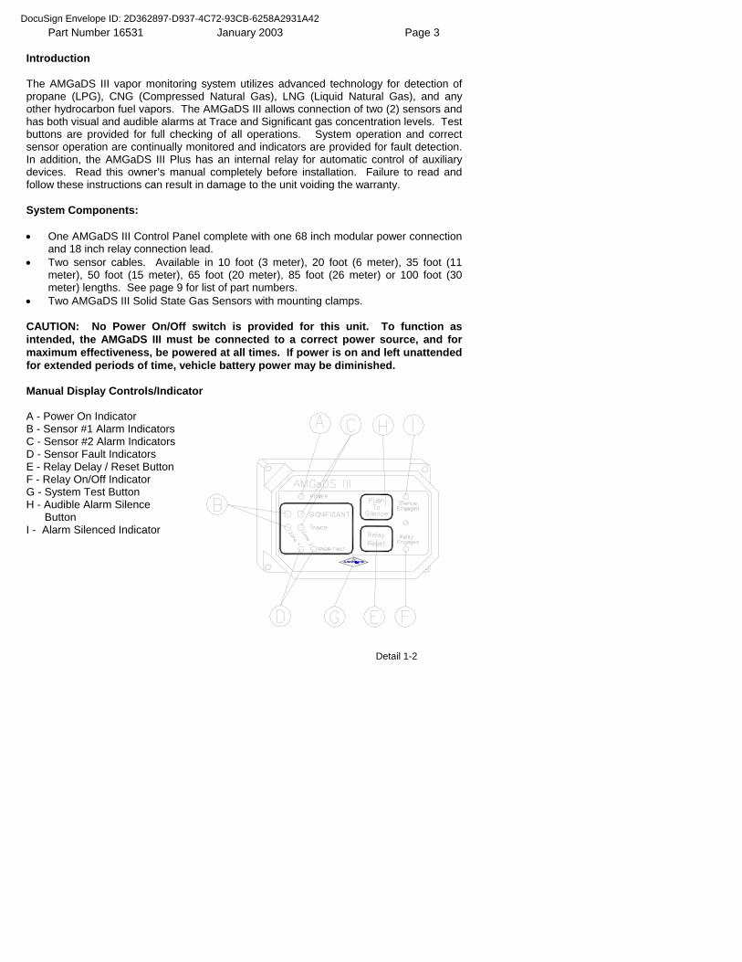
Part Number 16531 January 2003 Page 3 Introduction The AMGaDS III vapor monitoring system utilizes advanced technology for detection of propane (LPG), CNG (Compressed Natural Gas), LNG (Liquid Natural Gas), and any other hydrocarbon fuel vapors. The AMGaDS III allows connection of two (2) sensors and has both visual and audible alarms at Trace and Significant gas concentration levels. Test buttons are provided for full checking of all operations. System operation and correct sensor operation are continually monitored and indicators are provided for fault detection. In addition, the AMGaDS III Plus has an internal relay for automatic control of auxiliary devices. Read this owner’s manual completely before installation. Failure to read and follow these instructions can result in damage to the unit voiding the warranty. System Components: • One AMGaDS III Control Panel complete with one 68 inch modular power connection
and 18 inch relay connection lead. • Two sensor cables. Available in 10 foot (3 meter), 20 foot (6 meter), 35 foot (11
meter), 50 foot (15 meter), 65 foot (20 meter), 85 foot (26 meter) or 100 foot (30 meter) lengths. See page 9 for list of part numbers.
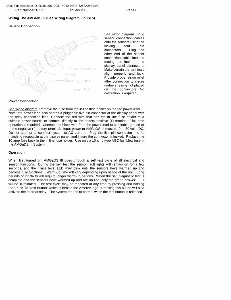
• Two AMGaDS III Solid State Gas Sensors with mounting clamps. CAUTION: No Power On/Off switch is provided for this unit. To function as intended, the AMGaDS III must be connected to a correct power source, and for maximum effectiveness, be powered at all times. If power is on and left unattended for extended periods of time, vehicle battery power may be diminished. Manual Display Controls/Indicator A - Power On Indicator B - Sensor #1 Alarm Indicators C - Sensor #2 Alarm Indicators D - Sensor Fault Indicators E - Relay Delay / Reset Button F - Relay On/Off Indicator G - System Test Button H - Audible Alarm Silence Button I - Alarm Silenced Indicator Detail 1-2
DocuSign Envelope ID: 2D362897-D937-4C72-93CB-6258A2931A42
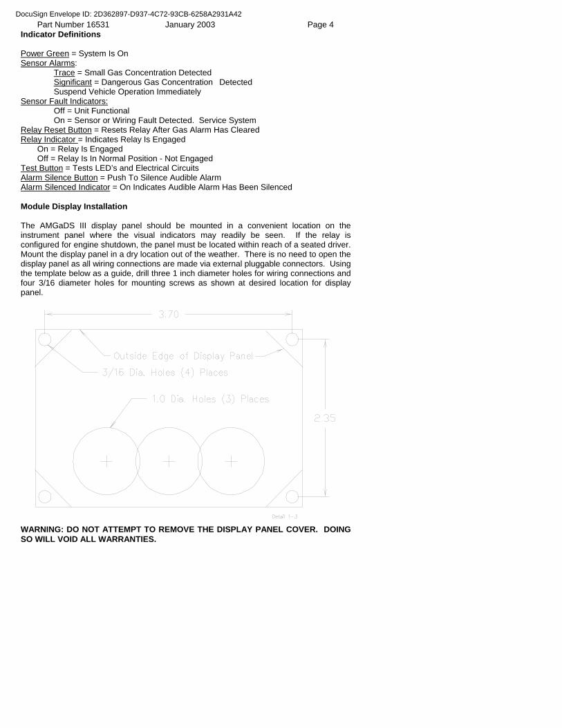
Part Number 16531 January 2003 Page 4 Indicator Definitions Power Green = System Is On Sensor Alarms: Trace = Small Gas Concentration Detected Significant = Dangerous Gas Concentration Detected Suspend Vehicle Operation Immediately Sensor Fault Indicators: Off = Unit Functional On = Sensor or Wiring Fault Detected. Service System Relay Reset Button = Resets Relay After Gas Alarm Has Cleared Relay Indicator = Indicates Relay Is Engaged On = Relay Is Engaged Off = Relay Is In Normal Position - Not Engaged Test Button = Tests LED’s and Electrical Circuits Alarm Silence Button = Push To Silence Audible Alarm Alarm Silenced Indicator = On Indicates Audible Alarm Has Been Silenced Module Display Installation The AMGaDS III display panel should be mounted in a convenient location on the instrument panel where the visual indicators may readily be seen. If the relay is configured for engine shutdown, the panel must be located within reach of a seated driver. Mount the display panel in a dry location out of the weather. There is no need to open the display panel as all wiring connections are made via external pluggable connectors. Using the template below as a guide, drill three 1 inch diameter holes for wiring connections and four 3/16 diameter holes for mounting screws as shown at desired location for display panel.
WARNING: DO NOT ATTEMPT TO REMOVE THE DISPLAY PANEL COVER. DOING SO WILL VOID ALL WARRANTIES.
DocuSign Envelope ID: 2D362897-D937-4C72-93CB-6258A2931A42
Part Number 16531 January 2003 Page 5 Attach the keyed locking wiring connectors to their mating receptacles on the back of the display panel, feed the lead wires through the one inch holes and attach the display panel to the vehicle using appropriate bolts or self tapping screws. Sensor Installation The sensors supplied with the AMGaDS III connect to the display panel via cables with pluggable wiring connectors. Do not shorten or attempt to splice this cable. Doing so will affect the sensitivity of the unit. Cables are available in lengths of 10, 20, 35, 50, 65, 85 and 100 feet. (See list of replacement parts at the end of this manual). Coil excessive cable in a convenient location and secure to the vehicle. Attach the sensors to the vehicle using the padded clamps provided for that purpose. Connect the sensors to the sensor cable from the display panel. CAUTION: Do not attempt to use any other manufacturer’s sensor or previously installed sensors. It is necessary to use only genuine Amerex AMGaDS III sensors, which are designed specifically for this unit, from your Amerex dealer. Replacement sensors are available as Amerex P/N 14198. Sensor Location CAUTION: For proper system function it is critical to know whether the fuel vapors the AMGaDS III system will be detecting are lighter or heavier than air. Mount the sensors where they will be as dry as possible. Water, mud, grease etc. can mask gas fumes from the sensor element. Do not mount in the direct path of road spray or oil spray. DO NOT locate the methane sensor in an area where heat will exceed 212º F. Propane is heavier than air and will settle. Therefore, it is important that sensor locations be selected that are as low as practical and below potential leak points such as valves and fittings when detecting propane. CNG (Compressed Natural Gas), LNG (Liquid Natural Gas), Methanol & Hydrogen are lighter than air and will rise. Therefore, it is important that a location be selected that is above potential leak points. Ideally, the sensors should be located in cavities as high as possible where rising gas will be trapped. Should you wish to detect vapors not listed above please contact Amerex Engineering to determine if AMGaDS III is suitable for your application. Auxiliary Relay Wiring The display panel of the AMGaDS III Plus contains an auxiliary single pole double throw (SPDT) relay that transfers 15 seconds after a Significant level gas concentration is detected. Typically this relay is used to shut off fuel supply or activate an auxiliary alarm. The relay is rated for 5 amps at 30 VDC. DO NOT exceed the maximum rating for this output.
DocuSign Envelope ID: 2D362897-D937-4C72-93CB-6258A2931A42
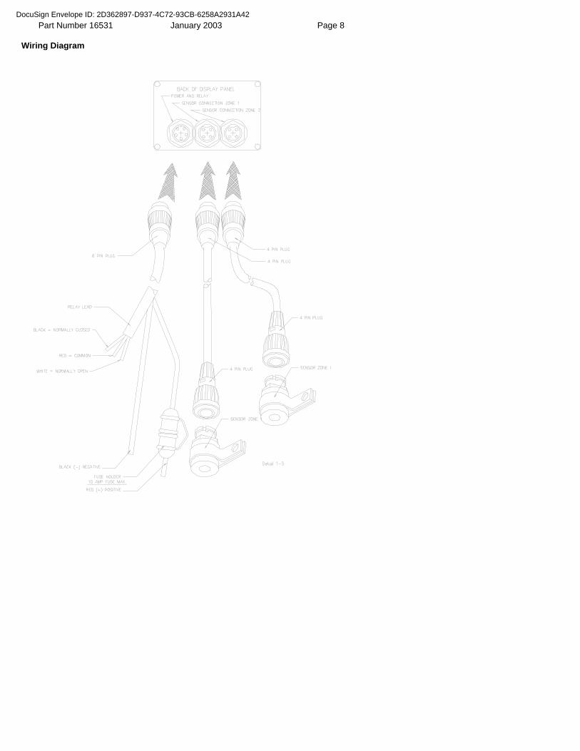
Part Number 16531 January 2003 Page 6 Wiring The AMGaDS III (See Wiring Diagram Figure 5) Sensor Connection
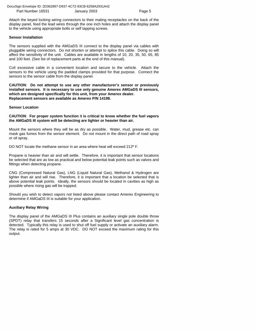
See wiring diagram. Plug sensor connection cables onto the sensors using the locking four pin connectors. Plug the other end of the sensor connection cable into the mating terminal on the display panel connectors. Make certain the terminals align properly and lock. Provide proper strain relief after connection to insure undue stress is not placed on the connectors No calibration is required.
Power Connection See wiring diagram Remove the fuse from the in line fuse holder on the red power lead. Note: the power lead also shares a pluggable five pin connector at the display panel with the relay connection lead. Connect the red wire that has the in line fuse holder to a suitable power source or connect directly to the battery positive (+) terminal if full time operation is required. Connect the black wire from the power lead to a suitable ground or to the negative (-) battery terminal. Input power to AMGaDS III must be 9 to 30 volts DC. Do not attempt to connect system to AC current. Plug the five pin connector into its matching receptacle at the display panel, and insure the connector is locked. Replace the 10 amp fuse back in the in line fuse holder. Use only a 10 amp type AGC fast blow fuse in the AMGaDS III System. Operation When first turned on, AMGaDS III goes through a self test cycle of all electrical and sensor functions. During the self test the sensor fault lights will remain on for a few seconds, and the Trace level LED may blink until the sensors have warmed up and become fully functional. Warm-up time will vary depending upon usage of the unit. Long periods of inactivity will require longer warm-up periods. When the self diagnostic test is complete and the sensors have warmed up and are on line, only the green “Power” LED will be illuminated. The test cycle may be repeated at any time by pressing and holding the “Push To Test Button” which is behind the Amerex logo. Pressing this button will also activate the internal relay. The system returns to normal when the test button is released.
DocuSign Envelope ID: 2D362897-D937-4C72-93CB-6258A2931A42
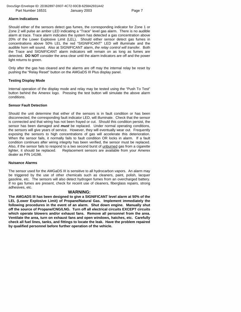
Part Number 16531 January 2003 Page 7 Alarm Indications Should either of the sensors detect gas fumes, the corresponding indicator for Zone 1 or Zone 2 will pulse an amber LED indicating a “Trace” level gas alarm. There is no audible alarm at trace. Trace alarm indicates the system has detected a gas concentration above 20% of the Lower Explosive Limit (LEL). Should either sensor detect gas fumes in concentrations above 50% LEL the red “SIGNIFICANT” LED will illuminate and the audible horn will sound. Also at SIGNIFICANT alarm, the relay control will transfer. Both the Trace and SIGNIFICANT alarm indicators will remain on as long as fumes are detected. DO NOT consider the area clear until the alarm indicators are off and the power light returns to green. Only after the gas has cleared and the alarms are off may the internal relay be reset by pushing the “Relay Reset” button on the AMGaDS III Plus display panel. Testing Display Mode Internal operation of the display mode and relay may be tested using the “Push To Test” button behind the Amerex logo. Pressing the test button will simulate the above alarm conditions. Sensor Fault Detection Should the unit determine that either of the sensors is in fault condition or has been disconnected, the corresponding fault indicator LED, will illuminate. Check that the sensor is connected and that wiring has not been frayed or cut. Should this condition persist, the sensor has been damaged and must be replaced. Under normal operating conditions, the sensors will give years of service. However, they will eventually wear out. Frequently exposing the sensors to high concentrations of gas will accelerate this deterioration. When the sensor fails, it normally fails to fault condition OR locks in alarm. If a fault condition continues after wiring integrity has been verified, the sensor must be replaced. Also, if the sensor fails to respond to a two second burst of unburned gas from a cigarette lighter, it should be replaced. Replacement sensors are available from your Amerex dealer as P/N 14198. Nuisance Alarms The sensor used for the AMGaDS III is sensitive to all hydrocarbon vapors. An alarm may be triggered by the use of other chemicals such as cleaners, paint, polish, lacquer gasoline, etc. The sensors will also detect hydrogen fumes from an overcharged battery. If no gas fumes are present, check for recent use of cleaners, fiberglass repairs, strong adhesives, etc.
WARNING: The AMGADS III has been designed to give a SIGNIFICANT level alarm at 50% of the LEL (Lower Explosive Limit) of Propane/Natural Gas. Implement immediately the following procedures in the event of an alarm. Shut down engine. Manually shut off the source of Propane/CNG/LNG. Turn off all electrical circuits EXCEPT circuits which operate blowers and/or exhaust fans. Remove all personnel from the area. Ventilate the area, turn on exhaust fans and open windows, hatches, etc. Carefully check all fuel lines, tanks, and fittings to locate the leak. Have the problem repaired by qualified personnel before further operation of the vehicle.
DocuSign Envelope ID: 2D362897-D937-4C72-93CB-6258A2931A42
Part Number 16531 January 2003 Page 8 Wiring Diagram
DocuSign Envelope ID: 2D362897-D937-4C72-93CB-6258A2931A42
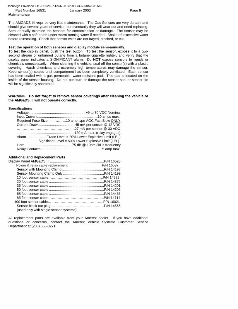
Part Number 16531 January 2003 Page 9 Maintenance The AMGADS III requires very little maintenance. The Gas Sensors are very durable and should give several years of service, but eventually they will wear out and need replacing. Semi-annually examine the sensors for contamination or damage. The sensor may be cleaned with a soft brush under warm running water if needed. Shake off excessive water before reinstalling. Check that sensor wires are not frayed, pinched, or cut. Test the operation of both sensors and display module semi-annually. To test the display panel, push the test button. To test the sensor, expose it to a two-second stream of unburned butane from a butane cigarette lighter, and verify that the display panel indicates a SIGNIFICANT alarm. Do NOT expose sensors to liquids or chemicals unnecessarily. When cleaning the vehicle, seal off the sensor(s) with a plastic covering. Harsh chemicals and extremely high temperatures may damage the sensor. Keep sensor(s) sealed until compartment has been completely ventilated. Each sensor has been sealed with a gas permeable, water-resistant pad. This pad is located on the inside of the sensor housing. Do not puncture or damage the sensor seal or sensor life will be significantly shortened. WARNING: Do not forget to remove sensor coverings after cleaning the vehicle or the AMGaDS III will not operate correctly. Specifications Voltage .........................................................+9 to 30 VDC Nominal Input Current........................................................…..10 amps max. Required Fuse Size......………..10 amp type AGC Fast Blow ONLY Current Draw ..................................... 45 mA per sensor @ 12 VDC ……………………………………….….27 mA per sensor @ 30 VDC ......................................................... 130 mA max. (relay engaged) Alarm .................... Trace Level = 20% Lower Explosive Limit (LEL) . Significant Level = 50% Lower Explosive Limit (LEL) Horn................................................ 75 dB @ 10cm 3kHz frequency Relay Contacts ..............................................................5 amp max. Additional and Replacement Parts Display Panel AMGaDS III .......................................................P/N 16528 Power & relay cable replacement P/N 16537 Sensor with Mounting Clamp...........................................P/N 14198 Sensor Mounting Clamp Only..........................................P/N 14199 10 foot sensor cable………………………………………..P/N 14925 20 foot sensor cable ........................................................P/N 14376 35 foot sensor cable ........................................................P/N 14201 50 foot sensor cable ........................................................P/N 14203 65 foot sensor cable ........................................................P/N 14466 85 foot sensor cable………………………….……………..P/N 14714 100 foot sensor cable…………………………….…………..P/N 16021 Sensor block out plug……………………………….………P/N 14555 (used only with single sensor systems) All replacement parts are available from your Amerex dealer. If you have additional questions or concerns, contact the Amerex Vehicle Systems Customer Service Department at (205) 655-3271.
DocuSign Envelope ID: 2D362897-D937-4C72-93CB-6258A2931A42
Part Number 16531 January 2003 Page 10
WARNING
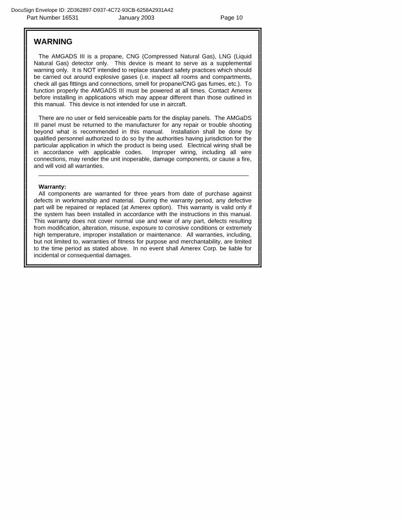
The AMGADS III is a propane, CNG (Compressed Natural Gas), LNG (Liquid Natural Gas) detector only. This device is meant to serve as a supplemental warning only. It is NOT intended to replace standard safety practices which should be carried out around explosive gases (i.e. inspect all rooms and compartments, check all gas fittings and connections, smell for propane/CNG gas fumes, etc.). To function properly the AMGADS III must be powered at all times. Contact Amerex before installing in applications which may appear different than those outlined in this manual. This device is not intended for use in aircraft.
There are no user or field serviceable parts for the display panels. The AMGaDS
III panel must be returned to the manufacturer for any repair or trouble shooting beyond what is recommended in this manual. Installation shall be done by qualified personnel authorized to do so by the authorities having jurisdiction for the particular application in which the product is being used. Electrical wiring shall be in accordance with applicable codes. Improper wiring, including all wire connections, may render the unit inoperable, damage components, or cause a fire, and will void all warranties.
________________________________________________________________ Warranty: All components are warranted for three years from date of purchase against
defects in workmanship and material. During the warranty period, any defective part will be repaired or replaced (at Amerex option). This warranty is valid only if the system has been installed in accordance with the instructions in this manual. This warranty does not cover normal use and wear of any part, defects resulting from modification, alteration, misuse, exposure to corrosive conditions or extremely high temperature, improper installation or maintenance. All warranties, including, but not limited to, warranties of fitness for purpose and merchantability, are limited to the time period as stated above. In no event shall Amerex Corp. be liable for incidental or consequential damages.
DocuSign Envelope ID: 2D362897-D937-4C72-93CB-6258A2931A42
State of Califomia-Business, Transportation and Housing Agency ARNOLD SCHWARZENEGGER, Governor
DEPARTMENT OF CALIFORNIA HIGHWAY PATROLP. O. Box 942898Sacramento, CA 94298-0001(916) 445-3253(800) 735-2929 (TTITDD)(800) 735-2922 (Voice)
July 6, 2009
File No.: 60.62.A8147.9-1-0393
Mr. Robert LangerAmerex CorporationP. O. Box 81Trussville, AL 35173-0081
Dear M!. Langer:
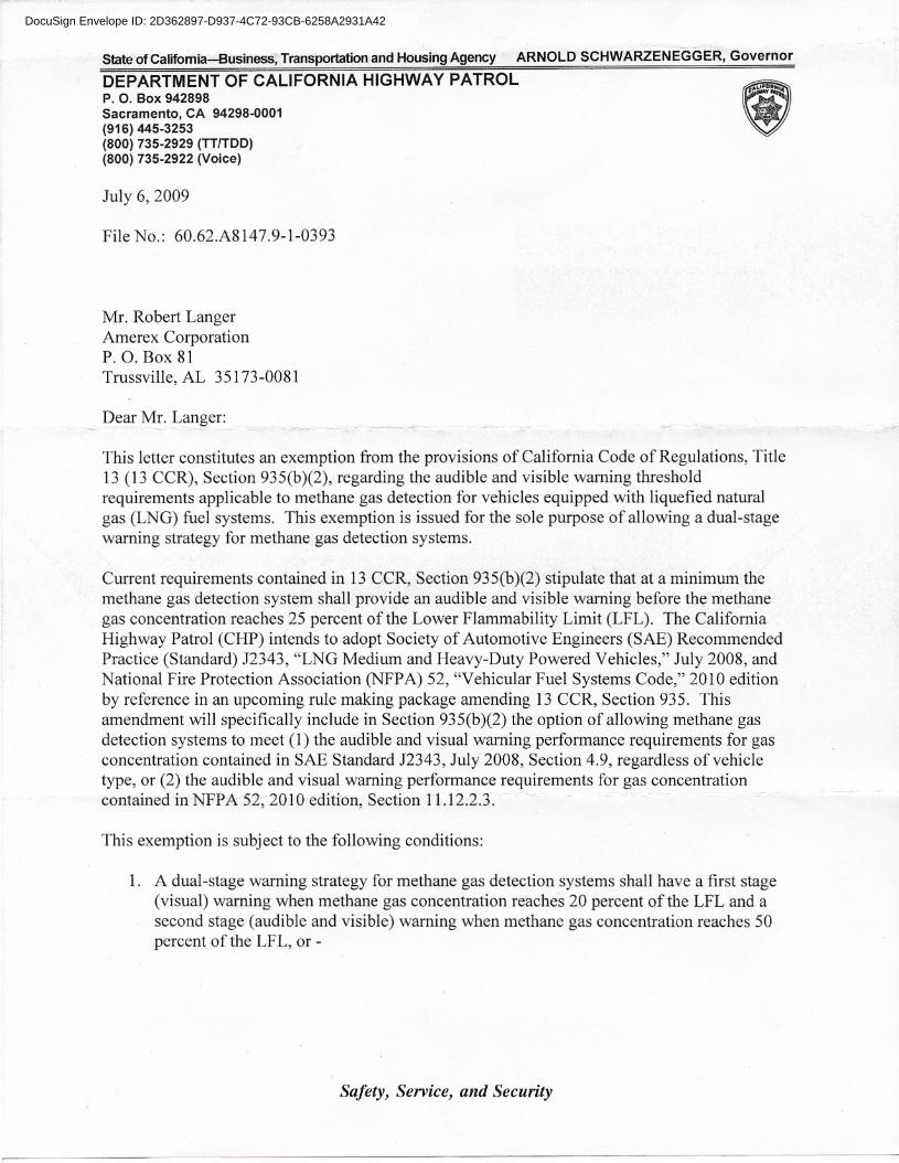
This letter constitutes an exemption from the provisions of California Code of Regulations, Title13 (13 CCR), Section 935(b)(2), regarding the audible and visible warning thresholdrequirements applicable to methane gas detection for vehicles equipped with liquefied naturalgas (LNG) fuel systems. This exemption is issued for the sole purpose of allowing a dual-stagewarning strategy for methane gas detection systems.
Current requirements contained in 13 CCR, Section 935(b)(2) stipulate that at a minimum themethane gas detection system shall provide an audible and visible warning before themethanegas concentration reaches 25 percent of the Lower Flammability Limit (LFL). The CaliforniaHighway Patrol (CHP) intends to adopt Society of Automotive Engineers (SAE) RecommendedPractice (Standard) J2343, "LNG Medium and Heavy-Duty Powered Vehicles," July 2008, andNational Fire Protection Association (NFPA) 52, "Vehicular Fuel Systems Code," 2010 editionby reference in an upcoming rule making package amending 13 CCR, Section 935. Thisamendment will specifically include in Section 935(b )(2) the option of allowing methane gasdetection systems to meet (1) the audible and visual warning performance requirements for gasconcentration contained in SAE Standard J2343, July 2008, Section 4.9, regardless of vehicletype, or (2) the audible and visual warning performance requirements for gas concentrationcontainechn NFPA 52, 2010 edition, Section 11.12.2.3. ~
This exemption is subject to the following conditions:
1. A dual-stage warning strategy for methane gas detection systems shall have a first stage(visual) warning when methane gas concentration reaches 20 percent of the LFL and asecond stage (audible and visible) warning when methane gas concentration reaches 50percent of the LFL, or -
Safety, Service, and Security
DocuSign Envelope ID: 2D362897-D937-4C72-93CB-6258A2931A42
Mr. Robert LangerPage 2July 6, 2009
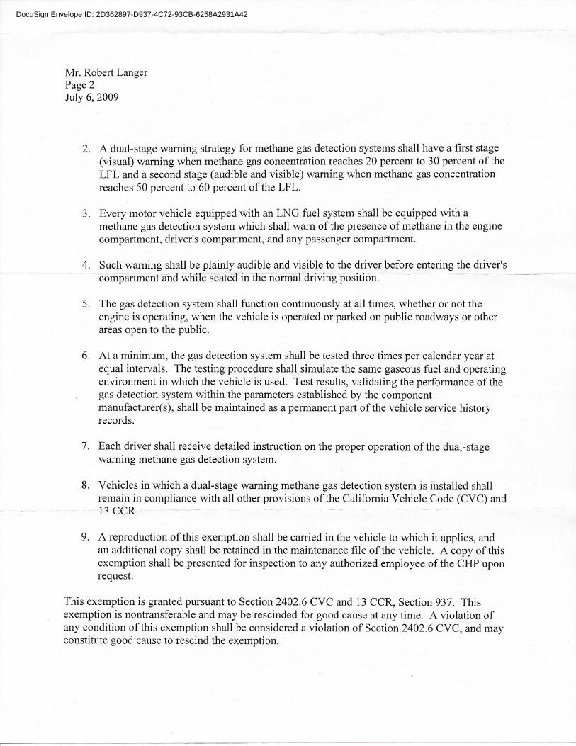
2. A dual-stage warning strategy for methane gas detection systems shall have a first stage(visual) warning when methane gas concentration reaches 20 percent to 30 percent of theLFL and a second stage (audible and visible) warning when methane gas concentrationreaches 50 percent to 60 percent of the LFL.
3. Every motor vehicle equipped with an LNG fuel system shall be equipped with amethane gas detection system which shall warn of the presence of methane in the enginecompartment, driver's compartment, and any passenger compartment.
4. Such warning shall be plainly audible and visible to the driver before entering the driver's- --compartment arid wliileseatea- illllie normal driviiigposition.~- -- -~---._-
5. The gas detection system shall function continuously at all times, whether or not theengine is operating, when the vehicle is operated or parked on public roadways or otherareas open to the public.
6. At a minimum, the gas detection system shall be tested three times per calendar year atequal intervals. The testing procedure shall simulate the same gaseous fuel and operatingenvironment in which the vehicle is used. Test results, validating the performance of thegas detection system within the parameters established by the componentmanufacturer(s), shall be maintained as a permanent part of the vehicle service historyrecords.
7. Each driver shall receive detailed instruction on the proper operation of the dual-stagewarning methane gas detection system.
8. Vehicles in which a dual-stage warning methane gas detection system is installed shallremain in compliance with all other provisions of the California Vehicle Code (CVC) and13 eCR. - -- ~-- .. -.- -
9. A reproduction of this exemption shall be carried in the vehicle to which it applies, andan additional copy shall be retained in the maintenance file of the vehicle. A copy of thisexemption shall be presented for inspection to any authorized employee of the CHP uponrequest.
This exemption is granted pursuant to Section 2402.6 CVC and 13 CCR, Section 937. Thisexemption is nontransferable and may be rescinded for good cause at any time. A violation ofany condition of this exemption shall be considered a violation of Section 2402.6 CVC, and mayconstitute good cause to rescind the exemption ..
DocuSign Envelope ID: 2D362897-D937-4C72-93CB-6258A2931A42
Mr. Robert LangerPage 3July 6, 2009
If you have any questions regarding this exemption, please contact Mr. Cris Morgan,Staff Engineer, Commercial Vehicle Section, at (916) 445-1865.
Sincerely,
DocuSign Envelope ID: 2D362897-D937-4C72-93CB-6258A2931A42