Embed Size (px)
Citation preview
APPENDIX VDL MODE 3AMCP WG-M/1 WP33
Amendment Proposal
Title:Original: AMCP WG M/-WP33
Editorial Input
AP working paper number and date M1/WP8 12 Dec 2000 Document(s) Affected: Manual on VDL Mode 3 Technical
SpecificationsDocument Version: 4.0 (WG-D/12 Report) Sections of Documents Affected: VariousCoordinator: Robert Morgenstern Coordinator's Address: 1820 Dolley Madison Blvd, M/S W387
McLean, VA 22102USA
Coordinator's Phone: +1 703 883 7846 Coordinator's Fax: +1 703 883 1367 Coordinator's E-mail Address: [email protected]: EDITORIALProblem description: Editorial corrections from review effort to
publish RTCA MASPS documentBackground: Secretariat requested editorial input on the
documentationValidated by inspection.
Backwards compatibility: No issuesAmendment Proposal: See attached for specific changes to TM.WG-M Status: RESOLVED AS AMENDED 15/12/00
APPROVED
APPENDIX VDL MODE 3AMCP WG-M/1 WP33
5.5.1.2 Channel occupancy. Channel occupancy shall be considered as the amount of time spent on the channel per access event.
For data operation, an access event shall consist of no more than 15 consecutive V/D (data) burst opportunities. For downlink data transmission, an access event shall be the result of a single Reservation Request.
For voice operation, an access event shall not be limited to a fixed number of V/D (voice) burst opportunities. However, voice operation shall honor the voice signaling information issued in the M uplink burst. An access event shall correspond with each push-to-talk (PTT) assertion. The maximum duration of a single aircraft radio PTT event shall be limited to 35 seconds. The PTT event shall be automatically terminated and the user being terminated shall be alerted to the termination.
5.5.2.1.5 External time reference interface. The VDL Mode 3 ground stations shall have the option to synchronize their station TDMA system timing clocks to a common absolute time standard. This external time source shall provide a timing strobe once per second on the second and a separate strobe onmeans to identify epoch boundaries. For purposes of providing epoch strobes, the external time source shall be aligned to UTC on 6 January 1980.
5.5.2.4 System configurations. The VDL Mode 3 shall recognize and support the set of system configurations identified in Table 5-47.
Note 1. All the configurations except 3T are called non-3T configurations .
Note 2. See the Implementation Aspects for the applications and descriptions of each System Configuration.
5.5.2.5 MEDIA ACCESS CONTROL CYCLE
Media access shall be based on a MAC cycle of 240 ms (two consecutive TDMA frames, denoted even and odd frames, Figure 5-3a).
Note. MAC cycles for each System Configuration are shown in the Implementation Aspects.
5.5.2.5.1 Logical burst access channels. For all configurations (except 3T, 3S and 2S1X), VDL Mode 3 shall grant media access individually for each of up to 8 separate LBACs numbered 1-8. A description of each LBAC for these cases (other than 3T, 3S and 2S1X) shall be as given by Table 5-48. For the 3T configuration, VDL Mode 3 shall grant media access individually for each of up to 18 separate Logical Burst Access Channels (LBACs) numbered 1-18. For each MAC cycle (3T), the timingA description for each LBAC for the 3T configuration shall be as given by Table 5-50. For the 3S configuration, VDL Mode 3 shall grant media access individually for each of up to 12 10 separate LBACs numbered 1-1210. For each MAC cycle (3S), the timingA description for each LBAC for the 3S configuration shall be as given by Table 5-51a. For the 2S1X, VDL Mode 3 shall grant media access individually for each of up to 7 separate LBACs numbered 1-7. For each MAC cycle (2S1X), the timingA description for each LBAC for the 2S1X configuration shall be as given by Table 5-51b. For all other configurations (except 3T, 3S and 2S1X), VDL shall grant media access individually for each of up to 8 separate LBACs numbered 1-8. A description of each LBAC for these cases (other than 3T, 3S and 2S1X) shall be as given by Table 5-48.
Note. MAC cycles for each System Configuration are shown labelled with each LBAC in the Implementation Aspects for VDL Mode 3.
APPENDIX VDL MODE 3AMCP WG-M/1 WP33
5.5.2.5.2 Burst access timing. The System Configuration code provided in the M uplink burst (Appendix B, Section B.2.1) shall be used by the aircraft VDL in conjunction with the timing reference point to establish proper burst timing. For all configurations (except 3T, 3S and 2S1X), LBACs shall be established according to Table 5-49; for the 3T configuration, LBACs shall be established according to Table 5-50; for 3S configuration, LBACs shall be established according to Table 5-51a; and for 2S1X configuration, LBACs shall be established according to Table 5-51b. ; and for other configurations (except 3T, 3S and 2S1X), LBACs shall be established according to Table 5-49. The timing reference point (TRP) shall be established per Section 5.5.4.1. The relative timings among the TRPs of different user groups for the various system configurations are shown in Table 5-51c.
5.5.3.1 Parameter t (truncation). This parameter shall be the number of MAC cycles which can elapse in normal timing state 1 (TS1) while not receiving a primary time reference (defined in Section 5.5.4.1.1) without requiring transmitted V/D (voice) bursts to be truncated.
Note: This parameter shall beis determined by the symbol clock stability of the aircraft VDL and represents the number of MAC cycles prior to accumulating a timing drift of 1 symbol periods.
5.5.3.1.1 Validity Window. Due to the 1 symbol period accuracy assumed for the aircraft radio timing, the aircraft radio shall establish a validity window also equal to 1 symbol period. A timing beacon shall beis only considered valid, i.e., acceptable for timing, if it is received within the validity window with respect to the previous beacon’s timing reference.
5.5.3.3 Parameter NM1 (maximum retry). The parameter NM1 is shall represent the maximum number of retransmissions of a random access Reservation Request message.
5.5.3.7 Parameter WR (reservation request retransmission delay). The parameter WR shall specifyies the number of MAC cycles that an aircraft radio shall wait before attempting a Reservation Request message retransmission.
5.5.4 Description of procedures
Media access shall observe the procedures described in this section in addition to observing the timing structure limitations of Section 5.5.2.1.
5.5.4.1 TIMING ACQUISITION AND MAINTENANCE
5.5.4.1.1 Primary timing reference. The aircraft VDL shall derive its primary timing from the received M uplink burst (LBAC 11 for 3T configuration, either LBAC 57, 97, or 911 for 3S configuration, either LBAC 4 or 6 for 2S1X, and LBAC 5 for other configurations) associated with its assigned user group and Ground Station Code. The timing reference point shall be established based on the center of the first received symbol of the synchronization sequence at the antenna port of the M uplink burst associated with the user group assigned. VDL media access opportunities for transmitted bursts shall be set relative to this reference in terms of transmitted symbol periods as shown in Tables 5-49, 5-50, and 5-51.
Note 1. To remain in the normal timing state (TS1), an aircraft VDL should maintain its primary timing to within ±1 symbol period of the correct time based on the position of the aircraft relative to the ground station. This timing tolerance is the basis for developing the timing state transition rules of Sections 5.5.4.1.4 and 5.5.4.1.5. Refer to Section 5.5.3.1 for this timing accuracy requirement.
APPENDIX VDL MODE 3AMCP WG-M/1 WP33
Note 2. The relative timings among the TRPs of the different user groups are as shown in Table 5-51c.
5.5.4.1.2 Alternate timing reference. When required by the procedures of Section 5.5.4.1.3 through Section 5.5.4.1.5, the aircraft VDL shall derive Alternate timing in truncate timing state 2 (TS2) from alternate timing sources (ATSs). ATSs are poll responses (except in the 3T configuration) associated with the user group or another user group (if available) and M uplink bursts in slots other than the one controlling the aircraft radio’s user group received during that MAC cycle. This alternate timing shall be derived based on the first received symbol of the synchronization sequence of the received poll responses or uplink M bursts. The aircraft VDL shall accept timing from ATSs if they obey the following rule:
Tr < Ta + 0.04 CTC2 Ts
where Ta is the expected time of an ATS as determined by the aircraft radio’s clock, Tr is the actual time of arrival of the ATS with respect to the aircraft radio’s clock, Ts is the symbol period, and CTC2 is the current value of the CTC2 counter (defined in Section 5.5.4.1.3). If CTC2 is greater than 800, all ATS time updates will shall be accepted. If the time is updated, CTC2 is reset to 0.
5.5.4.1.6 Dummy poll responses. When an aircraft radio receives an uplink M channel message with value 61 or 62 (Appendix B, Section B.2.1.4) in the Aircraft ID (Poll) field, indicating that the ground station does not support discrete addressing, an aircraft radio shall transmit dummy Poll Responses in downlink M slots reserved for Poll Response. The format of a dummy Poll Response shall be identical to a regular Poll Response. Dummy Poll Responses shall not be processed by the controlling ground station. The MAC cycle in which to transmit the dummy Poll Responses shall be chosen by the following algorithm:
Immediately after net initialization, after determining that the uplink Beacon contains Aircraft ID = 61 or 62, divide all further MAC cycles into groups of 25. Within each group, choose one MAC cycle at random from 1 to 25 in which to transmit a dummy Poll Response. Continue to transmit dummy Poll Responses for as long as the aircraft radio remains in timing state TS1.
Note 1. For the voice-only configurations: 4V, 3V, 3S and 2S1X, polling may not be implemented and a ground radio in one of these configurations may not support polling. In order to support the transmission of an Alternate Timing Reference in these configurations (see Section 5.5.4.1.2), aircraft radios must transmit “Dummy Poll Response” messages since they are never actually polled.
Note 2. Analysis and simulation have shown that, unless the number of aircraft radios is extremely large, the probability that at least one MAC cycle out of 25 contains one and only one dummy Poll Response is very close to 1.
Note 3. The LBACs available for dummy Poll Responses include LBAC 1 for configurations 4V, 3V, 3S, and 2S1X, irrespective of whichever LBAC is associated with the time slot the aircraft radio is currently connected to.
5.5.4.3.1 Polling. When directed by the ground LME the ground MAC sublayer shall transmit a Poll Request message. The aircraft MAC sublayer shall deliver a received Poll Request message to the aircraft LME. Upon receiving a Poll Response from the aircraft LME, the aircraft MAC sublayer shall stop the Reservation Request retransmission using the random access M-channel until a new request is generated. The aircraft station shall respond to a poll by the ground station by transmitting a Reservation Request message in LBAC 2, 3, or 4 for 3T configuration, and LBAC 1 for other configurations in the MAC cycle
APPENDIX VDL MODE 3AMCP WG-M/1 WP33
immediately following the poll. This opportunity to request a reservation shall be used consistent with the procedures of Section 5.5.4.4.3.3.3. If no reservation is needed by the aircraft VDL, the Number of Slots Requested field and the Voice Request field shall be set to zero.
The ground MAC sublayer shall deliver a received Poll Response message to the ground LME. The ground station shall respond to a Reservation Request message contained in a Poll Response using the procedures identified in Sections 5.5.4.4.3.3.1 and 5.5.4.4.3.3.3. No response shall be sent by the ground station if the number of slots in the reservation field is zero.
5.5.4.4.1 Segmentation function. The MAC sublayer shall perform segmentation of the user message longer than one data burst, as received from the upper layer, to support data burst transmission. The segmentation function shall observe the following procedures:
Each segment, except the last, shall occupy an entire data burst and shall set the EOM field of the Header segment to 0. Each segment of the user message shall include the Segment Number in the Segment Number field of the Header segment of each V/D (data) burst. The Segment Number shall begin with 1 for the first segment and shall be incremented by 1 for subsequent segments. The final segment of the user message shall set the EOM field to 1 to indicate to the peer MAC entity that the user message is completed. A Segment Number of 0 is reserved.
All downlink segments of the user message shall occupy only the time slots indicated in the Reservation Response field of the M uplink (Normal Message) burst (Section B.2.2 of Appendix B) user group and shall be transmitted in consecutive burst opportunities.
Any missing or corrupted segments shall result in discarding of the entire user message.
Note. The Maximum user message size is established by the maximum DLS frame group size assuring containment within a maximum of 15 V/D (data) bursts (Section 5.6.3.2).
5.5.4.4.2.1 Acknowledgement protocol. Upon receipt of an ACK frame from the local DLS sublayer, an Acknowledgement message shall be transmitted in the M burst downlink subchannel associated with the same slot one MAC cycle after the receipt of the last burst of the message being acknowledged, as illustrated in Figure 5-4. The downlink ACK frame shall not be transmitted in a V/D (data) burst. The peer MAC sublayer shall restore the ACK frame and forward it to the local DLS sublayer.
5.5.4.4.3.2 Assemble message for MAC data transfer. Every MAC cycle, the MAC sublayer shall determine if the transmit queue manager has traffic to be transmitted. The existence of traffic in the transmit queue manager shall cause the MAC sublayer to initiate the data transfer procedure described in Sections 5.5.4.4.3.3 through 5.5.4.4.3.6 below.
5.5.4.4.3.3.2 Reservation request acknowledgement. Upon receipt of a valid Reservation Request in the contention of M subchannels, the ground station shall respond with a Reservation Response message. This message shall be either a reservation or a Reservation Request Acknowledgement (RACK).
A Reservation Response message with slot assignment shall be sent to convey the actual slot assignment to the requester. A Reservation Response message with RACK shall be sent to the requester if the ground station is unable to honor the request due to unavailability of the time slots. The Reservation
APPENDIX VDL MODE 3AMCP WG-M/1 WP33
Response message with RACK shall not be sent in response to a Poll Response that cannot be immediately granted.
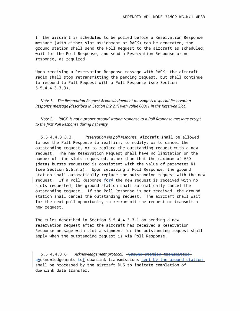
If the aircraft is scheduled to be polled before a Reservation Response message (with either slot assignment or RACK) can be generated, the ground station shall send the Poll Request to the aircraft as scheduled, wait for the Poll Response, and send a Reservation Response or no response, as required.
Upon receiving a Reservation Response message with RACK, the aircraft radio shall stop retransmitting the pending request, but shall continue to respond to Poll Request with a Poll Response (see Section 5.5.4.4.3.3.3).
Note 1. The Reservation Request Acknowledgement message is a special Reservation Response message (described in Section B.2.2.1) with value 00012 in the Reserved Slot.
Note 2. RACK is not a proper ground station response to a Poll Response message except to the first Poll Response during net entry.
5.5.4.4.3.3.3 Reservation via poll response. Aircraft shall be allowed to use the Poll Response to reaffirm, to modify, or to cancel the outstanding request, or to replace the outstanding request with a new request. The new Reservation Request shall have no limitation on the number of time slots requested, other than that the maximum of V/D (data) bursts requested is consistent with the value of parameter N1 (see Section 5.6.3.2). Upon receiving a Poll Response, the ground station shall automatically replace the outstanding request with the new request. If a Poll Response forf the new request is received with no slots requested, the ground station shall automatically cancel the outstanding request. If the Poll Response is not received, the ground station shall cancel the outstanding request. The aircraft shall wait for the next poll opportunity to retransmit the request or transmit a new request.
The rules described in Section 5.5.4.4.3.3.1 on sending a new reservation request after the aircraft has received a Reservation Response message with slot assignment for the outstanding request shall apply when the outstanding request is via Poll Response.
5.5.4.4.3.6 Acknowledgement protocol. Ground station transmitted aAcknowledgements tof downlink transmissions sent by the ground station shall be processed by the aircraft DLS to indicate completion of downlink data transfer.
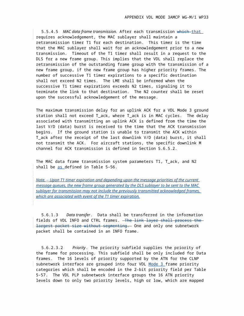
5.5.4.5 MAC data frame transmission. After each transmission which that requires acknowledgement, the MAC sublayer shall maintain a retransmission timer T1 for each destination. This timer is the time that the MAC sublayer shall wait for an acknowledgement prior to a new transmission. Timeout of the T1 timer shall result in a request to the DLS for a new frame group. This implies that the VDL shall replace the retransmission of the outstanding frame group with the transmission of a new frame group, if the new frame group has higher priority frames. The number of successive T1 timer expirations to a specific destination shall not exceed N2 times. The LME shall be informed when the successive T1 timer expirations exceeds N2 times, signaling it to terminate the link to that destination. The N2 counter shall be reset upon the successful acknowledgement of the message.
The maximum transmission delay for an uplink ACK for a VDL Mode 3 ground station shall not exceed T_ack, where T_ack is in MAC cycles. The delay associated with transmitting an uplink ACK is defined from the time the last V/D (data) burst is received to the time that the ACK transmission begins. If the ground station is unable to transmit the ACK within T_ack after the receipt of the last downlink V/D (data) burst, it shall not transmit the ACK. For aircraft stations, the specific downlink M channel for ACK transmission is defined in Section 5.6.5.2.
APPENDIX VDL MODE 3AMCP WG-M/1 WP33
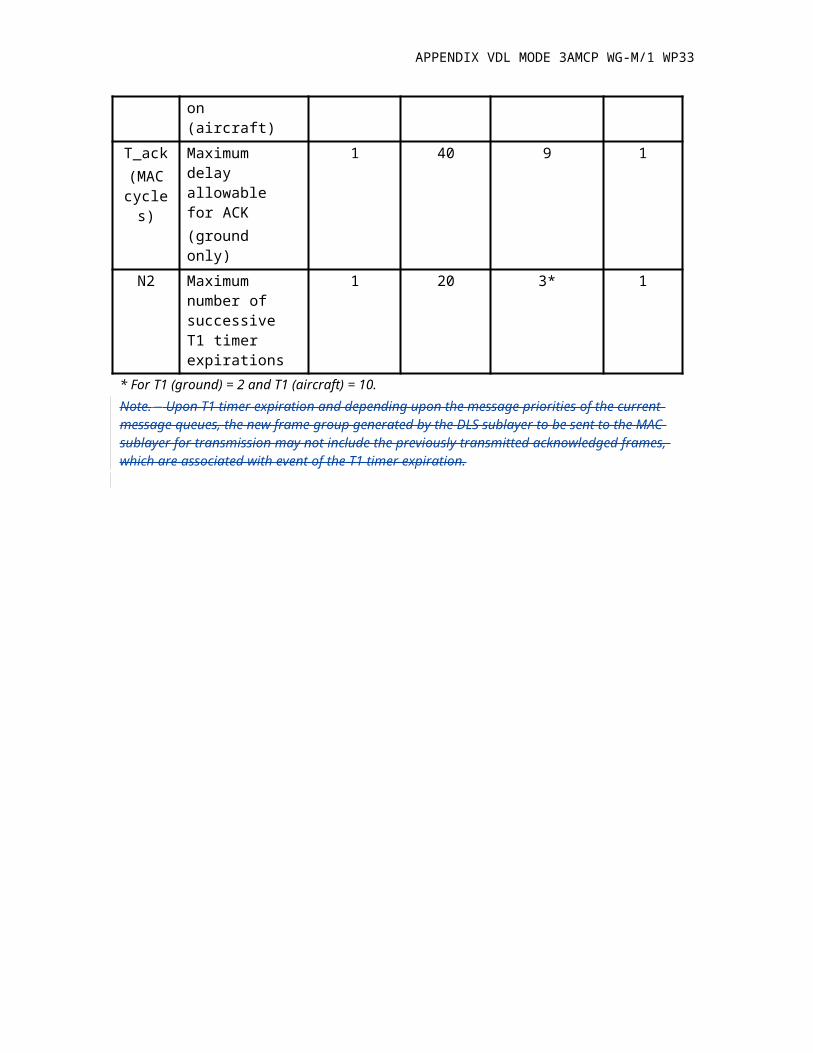
The MAC data frame transmission system parameters T1, T_ack, and N2 shall be as defined in Table 5-56.
Note. Upon T1 timer expiration and depending upon the message priorities of the current message queues, the new frame group generated by the DLS sublayer to be sent to the MAC sublayer for transmission may not include the previously transmitted acknowledged frames, which are associated with event of the T1 timer expiration.
5.6.1.3 Data transfer. Data shall be transferred in the information fields of VDL INFO and CTRL frames. The link layer shall process the largest packet size without segmenting. One and only one subnetwork packet shall be contained in an INFO frame.
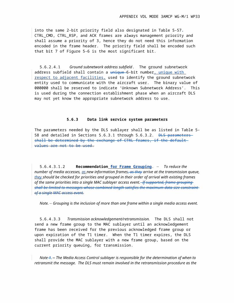
5.6.2.3.2 Priority. The priority subfield supplies the priority of the frame for processing. This subfield shall be only included for Data frames. The 16 levels of priority supported by the ATN for the CLNP subnetwork interface are grouped into four VDL Mode 3 frame priority categories which shall be encoded in the 2-bit priority field per Table 5-57. The VDL PLP subnetwork interface groups the 16 ATN priority levels down to only two priority levels, high or low, which are mapped into the same 2-bit priority field also designated in Table 5-57. CTRL_CMD, CTRL_RSP, and ACK frames are always management priority and shall assume a priority of 3, hence they do not need this information encoded in the frame header. The priority field shall be encoded such that bit 7 of Figure 5-6 is the most significant bit.
5.6.2.4.1 Ground subnetwork address subfield. The ground subnetwork address subfield shall contain a unique 6-bit number, unique with respect to adjacent facilities, used to identify the ground subnetwork entity used to communicate with the aircraft user. The binary value of 000000 shall be reserved to indicate ‘Unknown Subnetwork Address’. This is used during the connection establishment phase when an aircraft DLS may not yet know the appropriate subnetwork address to use.
5.6.3 Data link service system parameters
The parameters needed by the DLS sublayer shall be as listed in Table 5-58 and detailed in Sections 5.6.3.1 through 5.6.3.2. DLS parameters shall be determined by the exchange of CTRL frames, if the default values are not to be used.
5.6.4.3.1.2 Recommendation for Frame Grouping. To reduce the number of media accesses, as new information frames, as they arrive at the transmission queue, they should be checked for priorities and grouped in their order of arrival with existing frames of the same priorities into a single MAC sublayer access event. If supported, frame grouping shall be limited to messages whose combined length satisfies the maximum data size constraint of a single MAC access event.
Note. Grouping is the inclusion of more than one frame within a single media access event.
5.6.4.3.3 Transmission acknowledgement/retransmission. The DLS shall not send a new frame group to the MAC sublayer until an acknowledgement frame has been received for the previous acknowledged frame group or upon expiration of the T1 timer. When the T1 timer expires, the DLS shall
APPENDIX VDL MODE 3AMCP WG-M/1 WP33
provide the MAC sublayer with a new frame group, based on the current priority queuing, for transmission.
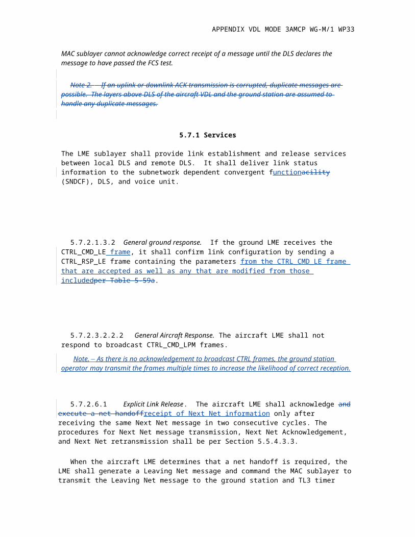
Note 1. The Media Access Control sublayer is responsible for the determination of when to retransmit the message. The DLS must remain involved in the retransmission procedure as the MAC sublayer cannot acknowledge correct receipt of a message until the DLS declares the message to have passed the FCS test.
Note 2. If an uplink or downlink ACK transmission is corrupted, duplicate messages are possible. The layers above DLS of the aircraft VDL and the ground station are assumed to handle any duplicate messages.
5.7.1 Services
The LME sublayer shall provide link establishment and release services between local DLS and remote DLS. It shall deliver link status information to the subnetwork dependent convergent functionacility (SNDCF), DLS, and voice unit.
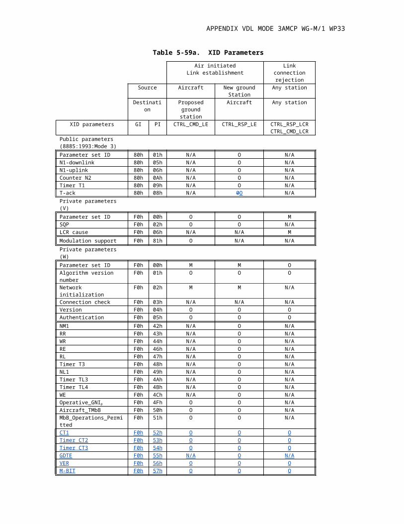
5.7.2.1.3.2 General ground response. If the ground LME receives the CTRL_CMD_LE frame, it shall confirm link configuration by sending a CTRL_RSP_LE frame containing the parameters from the CTRL_CMD_LE frame that are accepted as well as any that are modified from those includedper Table 5-59a.
5.7.2.3.2.2.2 General Aircraft Response. The aircraft LME shall not respond to broadcast CTRL_CMD_LPM frames.
Note. As there is no acknowledgement to broadcast CTRL frames, the ground station operator may transmit the frames multiple times to increase the likelihood of correct reception.
5.7.2.6.1 Explicit Link Release. The aircraft LME shall acknowledge and execute a net handoffreceipt of Next Net information only after receiving the same Next Net message in two consecutive cycles. The procedures for Next Net message transmission, Next Net Acknowledgement, and Next Net retransmission shall be per Section 5.5.4.3.3.
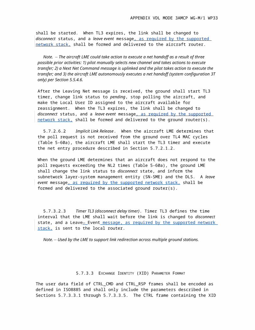
When the aircraft LME determines that a net handoff is required, the LME shall generate a Leaving Net message and command the MAC sublayer to transmit the Leaving Net message to the ground station and TL3 timer shall be started. When TL3 expires, the link shall be changed to disconnect status, and a leave event message, as required by the supported network stack, shall be formed and delivered to the aircraft router.
APPENDIX VDL MODE 3AMCP WG-M/1 WP33
Note. The aircraft LME could take action to execute a net handoff as a result of three possible prior activities: 1) pilot manually selects new channel and takes actions to execute transfer; 2) a Next Net Command message is uplinked and the pilot takes action to execute the transfer; and 3) the aircraft LME autonomously executes a net handoff (system configuration 3T only) per Section 5.5.4.6.
After the Leaving Net message is received, the ground shall start TL3 timer, change link status to pending, stop polling the aircraft, and make the Local User ID assigned to the aircraft available for reassignment. When the TL3 expires, the link shall be changed to disconnect status, and a leave event message, as required by the supported network stack, shall be formed and delivered to the ground router(s).
5.7.2.6.2 Implicit Link Release. When the aircraft LME determines that the poll request is not received from the ground over TL4 MAC cycles (Table 5-60a), the aircraft LME shall start the TL3 timer and execute the net entry procedure described in Section 5.7.2.1.2.
When the ground LME determines that an aircraft does not respond to the poll requests exceeding the NL2 times (Table 5-60a), the ground LME shall change the link status to disconnect state, and inform the subnetwork layer-system management entity (SN-SME) and the DLS. A leave event message, as required by the supported network stack, shall be formed and delivered to the associated ground router(s).
5.7.3.2.3 Timer TL3 (disconnect delay timer). Timer TL3 defines the time interval that the LME shall wait before the link is changed to disconnect state, and a Leave_ Event message, as required by the supported network stack, is sent to the local router.
Note. Used by the LME to support link redirection across multiple ground stations.
5.7.3.3 EXCHANGE IDENTITY (XID) PARAMETER FORMAT
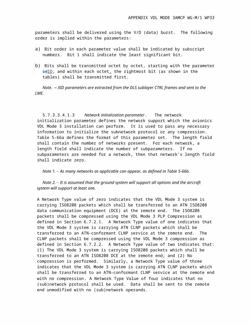
The user data field of CTRL_CMD and CTRL_RSP frames shall be encoded as defined in ISO8885 and shall only include the parameters described in Sections 5.7.3.3.1 through 5.7.3.3.5. The CTRL frame containing the XID parameters shall be delivered using the V/D (data) burst. The following order is implied within the parameters:
a) Bit order in each parameter value shall be indicated by subscript numbers. Bit 1 shall indicate the least significant bit.
b) Bits shall be transmitted octet by octet, starting with the parameter idID, and within each octet, the rightmost bit (as shown in the tables) shall be transmitted first.
Note. XID parameters are extracted from the DLS sublayer CTRL frames and sent to the LME.
5.7.3.3.4.1.3 Network initialization parameter. The network initialization parameter defines the network support which the avionics VDL Mode 3 installation can perform. It is used to pass any necessary information to initialize the subnetwork protocol or any compression. Table 5-66a defines the format of this parameter set. The length field shall contain the number of networks present. For each network, a length field shall indicate the number of subparameters. If no subparameters are needed for a network, then that network’s length field shall indicate zero.
APPENDIX VDL MODE 3AMCP WG-M/1 WP33
Note 1. As many networks as applicable can appear, as defined in Table 5-66b.
Note 2. It is assumed that the ground system will support all options and the aircraft system will support at least one.
A Network Type value of zero indicates that the VDL Mode 3 system is carrying ISO8208 packets which shall be transferred to an ATN ISO8208 data communication equipment (DCE) at the remote end. The ISO8208 packets shall be compressed using the VDL Mode 3 PLP Compression as defined in Section 6.7.2.1. A Network Type value of one indicates that the VDL Mode 3 system is carrying ATN CLNP packets which shall be transferred to an ATN-conformant CLNP service at the remote end. The CLNP packets shall be compressed using the VDL Mode 3 compression as defined in Section 6.7.2.2. A Network Type value of two indicates that: (1) The VDL Mode 3 system is carrying ISO8208 packets which shall be transferred to an ATN ISO8208 DCE at the remote end; and (2) No compression is performed. Similarly, a Network Type value of three indicates that the VDL Mode 3 system is carrying ATN CLNP packets which shall be transferred to an ATN-conformant CLNP service at the remote end with no compression. A Network Type Value of four indicates that no (sub)network protocol shall be used. Data shall be sent to the remote end unmodified with no (sub)network operands.
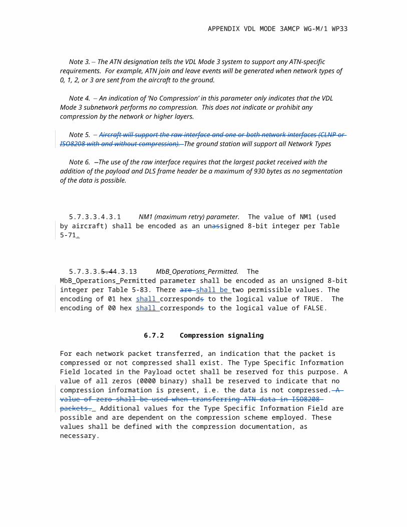
Note 3. The ATN designation tells the VDL Mode 3 system to support any ATN-specific
requirements. For example, ATN join and leave events will be generated when network types of 0, 1, 2, or 3 are sent from the aircraft to the ground.
Note 4. An indication of ‘No Compression’ in this parameter only indicates that the VDL Mode 3 subnetwork performs no compression. This does not indicate or prohibit any compression by the network or higher layers.
Note 5. Aircraft will support the raw interface and one or both network interfaces (CLNP or ISO8208 with and without compression). The ground station will support all Network Types
Note 6. —The use of the raw interface requires that the largest packet received with the addition of the payload and DLS frame header be a maximum of 930 bytes as no segmentation of the data is possible.
5.7.3.3.4.3.1 NM1 (maximum retry) parameter. The value of NM1 (used by aircraft) shall be encoded as an unassigned 8-bit integer per Table 5-71.
5.7.3.3.5.44.3.13 MbB_Operations_Permitted. The MbB_Operations_Permitted parameter shall be encoded as an unsigned 8-bit integer per Table 5-83. There are shall be two permissible values. The encoding of 01 hex shall corresponds to the logical value of TRUE. The encoding of 00 hex shall corresponds to the logical value of FALSE.
6.7.2 Compression signaling
For each network packet transferred, an indication that the packet is compressed or not compressed shall exist. The Type Specific Information Field located in the Payload octet shall be reserved for this purpose. A value of all zeros (0000 binary) shall be reserved to indicate that no compression information is present, i.e. the data is not compressed. A value of zero shall be used when transferring ATN data in ISO8208 packets. Additional values for the Type Specific Information Field are possible and are dependent on the compression scheme employed. These values shall be defined with the compression documentation, as necessary.
APPENDIX VDL MODE 3AMCP WG-M/1 WP33
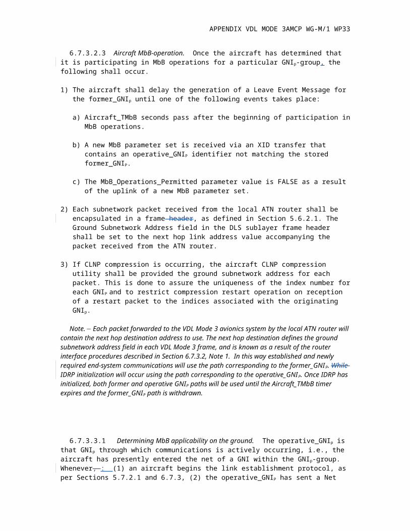
6.7.3.2.3 Aircraft MbB-operation. Once the aircraft has determined that it is participating in MbB operations for a particular GNIp-group, the following shall occur.
1) The aircraft shall delay the generation of a Leave Event Message for the former_GNIp until one of the following events takes place:
a) Aircraft_TMbB seconds pass after the beginning of participation in MbB operations.
b) A new MbB parameter set is received via an XID transfer that contains an operative_GNIP identifier not matching the stored former_GNIP.
c) The MbB_Operations_Permitted parameter value is FALSE as a result of the uplink of a new MbB parameter set.
2) Each subnetwork packet received from the local ATN router shall be encapsulated in a frame header, as defined in Section 5.6.2.1. The Ground Subnetwork Address field in the DLS sublayer frame header shall be set to the next hop link address value accompanying the packet received from the ATN router.
3) If CLNP compression is occurring, the aircraft CLNP compression utility shall be provided the ground subnetwork address for each packet. This is done to assure the uniqueness of the index number for each GNIP and to restrict compression restart operation on reception of a restart packet to the indices associated with the originating GNIp.
Note. Each packet forwarded to the VDL Mode 3 avionics system by the local ATN router will contain the next hop destination address to use. The next hop destination defines the ground subnetwork address field in each VDL Mode 3 frame, and is known as a result of the router interface procedures described in Section 6.7.3.2, Note 1. In this way established and newly required end-system communications will use the path corresponding to the former_GNIP. While IDRP initialization will occur using the path corresponding to the operative_GNIP. Once IDRP has initialized, both former and operative GNIP paths will be used until the Aircraft_TMbB timer expires and the former_GNIP path is withdrawn.
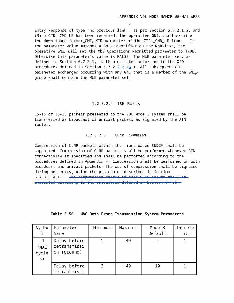
6.7.3.3.1 Determining MbB applicability on the ground. The operative_GNIp is that GNIp through which communications is actively occurring, i.e., the aircraft has presently entered the net of a GNI within the GNIp-group. Whenever, : (1) an aircraft begins the link establishment protocol, as per Sections 5.7.2.1 and 6.7.3, (2) the operative_GNIP has sent a Net Entry Response of type “no previous link”, as per Section 5.7.2.1.2, and (3) a CTRL_CMD_LE has been received, the operative_GNIP shall examine the downlinked former_GNIp XID parameter of the CTRL_CMD_LE frame. If the parameter value matches a GNIP identifier on the MbB-list, the operative_GNIP will set the MbB_Operations_Permitted parameter to TRUE. Otherwise this parameter’s value is FALSE. The MbB parameter set, as defined in Section 6.7.3.1, is then uplinked according to the XID procedures defined in Section 5.7.2.2.2.13.1. All subsequent XID parameter exchanges occurring with any GNI that is a member of the GNIp-group shall contain the MbB parameter set.
7.2.3.2.4 ISH PACKETS.
APPENDIX VDL MODE 3AMCP WG-M/1 WP33
ES-IS or IS-IS packets presented to the VDL Mode 3 system shall be transferred as broadcast or unicast packets as signaled by the ATN router.
7.2.3.2.5 CLNP COMPRESSION.
Compression of CLNP packets within the frame-based SNDCF shall be supported. Compression of CLNP packets shall be performed whenever ATN connectivity is specified and shall be performed according to the procedures defined in Appendix F. Compression shall be performed on both broadcast and unicast packets. The use of compression shall be signaled during net entry, using the procedures described in Section 5.7.3.3.4.1.3. The compression status of each CLNP packet shall be indicated according to the procedures defined in Section 6.7.1.
Table 5-56 MAC Data Frame Transmission System Parameters
Symbol Parameter Name Minimum Maximum Mode 3 Default IncrementT1
(MAC cycles)
Delay before retransmission (ground)
1 40 2 1
Delay before retransmission (aircraft)
2 40 10 1
T_ack(MAC cycles)
Maximum delay allowable for ACK(ground only)
1 40 9 1
N2 Maximum number of successive T1 timer expirations
1 20 3* 1
* For T1 (ground) = 2 and T1 (aircraft) = 10.Note. Upon T1 timer expiration and depending upon the message priorities of the current message queues, the new frame group generated by the DLS sublayer to be sent to the MAC sublayer for transmission may not include the previously transmitted acknowledged frames, which are associated with event of the T1 timer expiration.
APPENDIX VDL MODE 3AMCP WG-M/1 WP33
Table 5-59a. XID Parameters
Air initiatedLink establishment
Link connectionrejection
Source Aircraft New groundStation
Any station
Destination Proposed ground station
Aircraft Any station
XID parameters GI PI CTRL_CMD_LE CTRL_RSP_LE CTRL_RSP_LCRCTRL_CMD_LCR
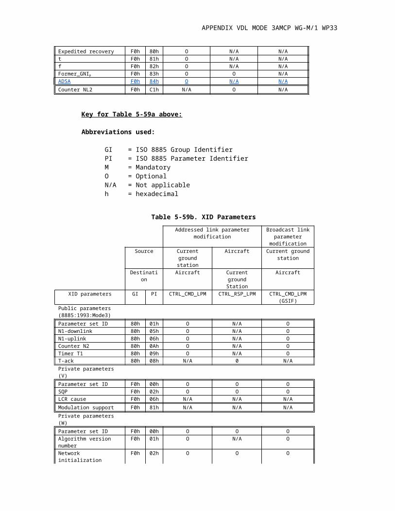
Public parameters(8885:1993:Mode 3)Parameter set ID 80h 01h N/A O N/AN1-downlink 80h 05h N/A O N/AN1-uplink 80h 06h N/A O N/ACounter N2 80h 0Ah N/A O N/ATimer T1 80h 09h N/A O N/AT-ack 80h 08h N/A 0O N/APrivate parameters (V)Parameter set ID F0h 00h O O MSQP F0h 02h O O N/ALCR cause F0h 06h N/A N/A MModulation support F0h 81h O N/A N/APrivate parameters (W)Parameter set ID F0h 00h M M OAlgorithm version number F0h 01h O O ONetwork initialization F0h 02h M M N/AConnection check F0h 03h N/A N/A N/AVersion F0h 04h O O OAuthentication F0h 05h O O ONM1 F0h 42h N/A O N/ARR F0h 43h N/A O N/AWR F0h 44h N/A O N/ARE F0h 46h N/A O N/ARL F0h 47h N/A O N/ATimer T3 F0h 48h N/A O N/ANL1 F0h 49h N/A O N/ATimer TL3 F0h 4Ah N/A O N/ATimer TL4 F0h 4Bh N/A O N/AWE F0h 4Ch N/A O N/AOperative_GNIp F0h 4Fh O O N/AAircraft_TMbB F0h 50h O O N/AMbB_Operations_Permitted F0h 51h O O N/ACT1 F0h 52h O O OTimer CT2 F0h 53h O O OTimer CT3 F0h 54h O O OGDTE F0h 55h N/A O N/AVER F0h 56h O O OM-BIT F0h 57h O O OExpedited recovery F0h 80h O N/A N/At F0h 81h O N/A N/Af F0h 82h O N/A N/AFormer_GNIp F0h 83h O O N/AADSA F0h 84h O N/A N/ACounter NL2 F0h C1h N/A O N/A
APPENDIX VDL MODE 3AMCP WG-M/1 WP33
Key for Table 5-59a above:
Abbreviations used:
GI = ISO 8885 Group IdentifierPI = ISO 8885 Parameter IdentifierM = MandatoryO = OptionalN/A = Not applicableh = hexadecimal
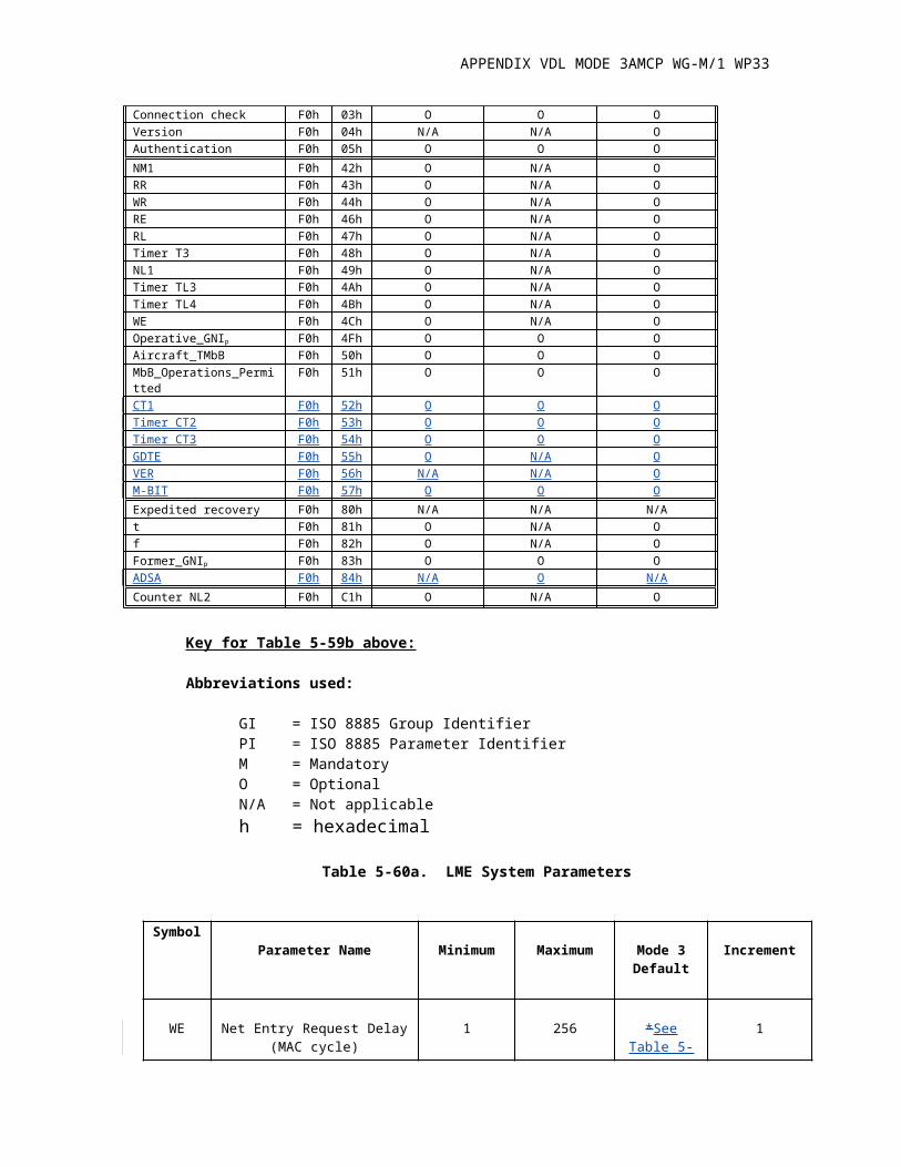
Table 5-59b. XID Parameters
Addressed link parameter modification Broadcast link parameter
modificationSource Current ground
stationAircraft Current ground
stationDestination Aircraft Current ground
StationAircraft
XID parameters GI PI CTRL_CMD_LPM CTRL_RSP_LPM CTRL_CMD_LPM(GSIF)
Public parameters (8885:1993:Mode3)Parameter set ID 80h 01h O N/A ON1-downlink 80h 05h O N/A ON1-uplink 80h 06h O N/A OCounter N2 80h 0Ah O N/A OTimer T1 80h 09h O N/A OT-ack 80h 08h N/A 0 N/APrivate parameters (V)Parameter set ID F0h 00h O O OSQP F0h 02h O O OLCR cause F0h 06h N/A N/A N/AModulation support F0h 81h N/A N/A N/APrivate parameters (W)Parameter set ID F0h 00h O O OAlgorithm version number F0h 01h O N/A ONetwork initialization F0h 02h O O OConnection check F0h 03h O O OVersion F0h 04h N/A N/A OAuthentication F0h 05h O O ONM1 F0h 42h O N/A ORR F0h 43h O N/A OWR F0h 44h O N/A ORE F0h 46h O N/A ORL F0h 47h O N/A OTimer T3 F0h 48h O N/A ONL1 F0h 49h O N/A OTimer TL3 F0h 4Ah O N/A OTimer TL4 F0h 4Bh O N/A OWE F0h 4Ch O N/A OOperative_GNIp F0h 4Fh O O OAircraft_TMbB F0h 50h O O OMbB_Operations_Permitted F0h 51h O O OCT1 F0h 52h O O OTimer CT2 F0h 53h O O OTimer CT3 F0h 54h O O OGDTE F0h 55h O N/A OVER F0h 56h N/A N/A OM-BIT F0h 57h O O OExpedited recovery F0h 80h N/A N/A N/At F0h 81h O N/A O
APPENDIX VDL MODE 3AMCP WG-M/1 WP33
f F0h 82h O N/A OFormer_GNIp F0h 83h O O OADSA F0h 84h N/A O N/ACounter NL2 F0h C1h O N/A O
Key for Table 5-59b above:
Abbreviations used:
GI = ISO 8885 Group IdentifierPI = ISO 8885 Parameter IdentifierM = MandatoryO = OptionalN/A = Not applicableh = hexadecimal
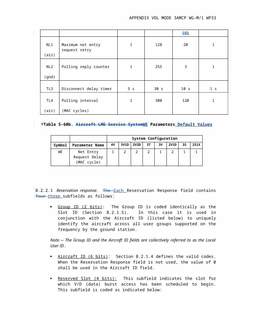
Table 5-60a. LME System Parameters
SymbolParameter Name Minimum Maximum Mode 3
DefaultIncrement
WE Net Entry Request Delay (MAC cycle)
1 256 *See Table 5-60b
1
NL1
(air)
Maximum net entry request retry
1 128 20 1
NL2
(gnd)
Polling reply counter 1 255 3 1
TL3 Disconnect delay timer 5 s 30 s 10 s 1 s
TL4
(air)
Polling interval
(MAC cycles)
1 300 120 1
*Table 5-60b. Aircraft LME Service SystemWE Parameters Default Values
System ConfigurationSymbol Parameter Name 4V 3V1D 2V2D 3T 3V 2V1D 3S 2S1X
WE Net Entry Request Delay (MAC cycle)
1 2 2 2 1 2 1 1
B.2.2.1 Reservation response. The Each Reservation Response field contains four three subfields as follows:
APPENDIX VDL MODE 3AMCP WG-M/1 WP33
Group ID (2 bits) : The Group ID is coded identically as the Slot ID (Section B.2.1.5). In this case it is used in conjunction with the Aircraft ID (listed below) to uniquely identify the aircraft across all user groups supported on the frequency by the ground station.
Note. The Group ID and the Aircraft ID fields are collectively referred to as the Local User ID.
Aircraft ID (6 bits) : Section B.2.1.4 defines the valid codes. When the Reservation Response field is not used, the value of 0 shall be used in the Aircraft ID field.
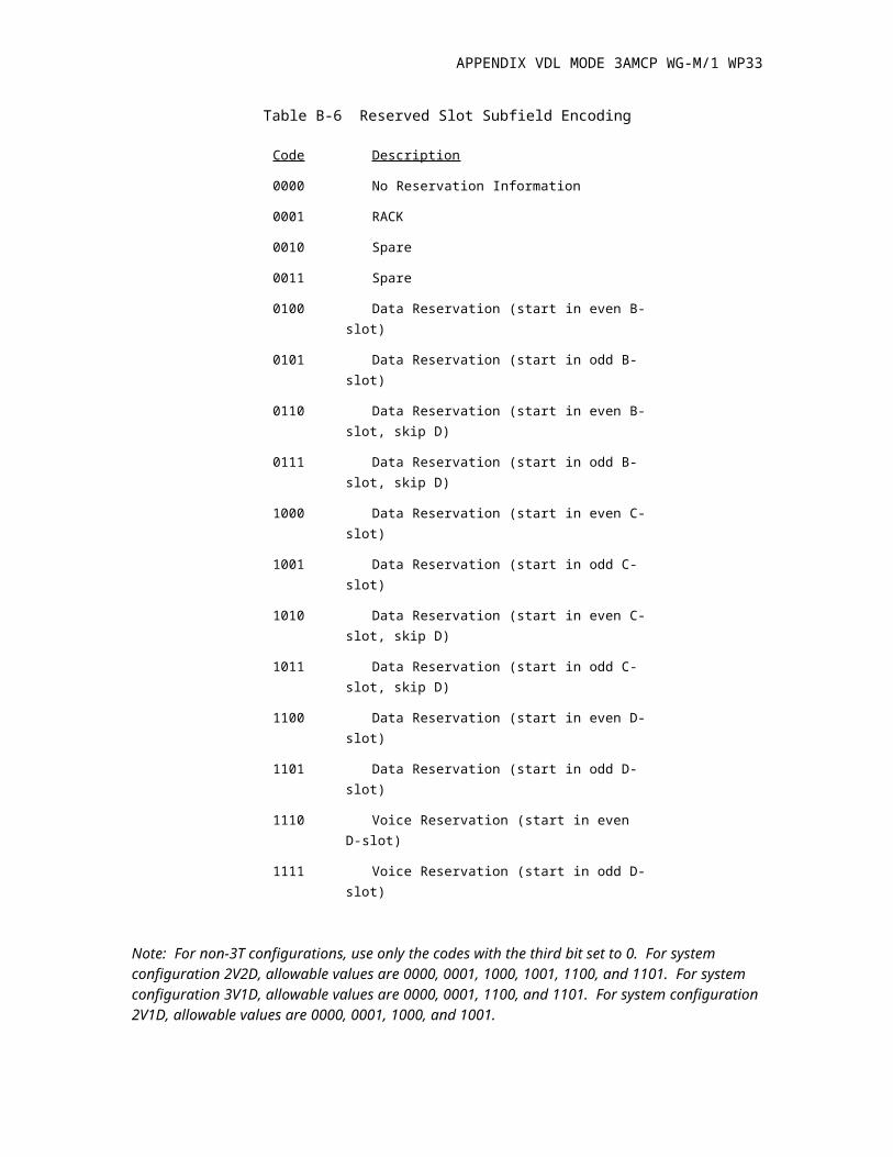
Reserved Slot (4 bits): This subfield indicates the slot for which V/D (data) burst access has been scheduled to begin. This subfield is coded as indicated below:
Table B-6 Reserved Slot Subfield Encoding
Code Description
0000 No Reservation Information
0001 RACK
0010 Spare
0011 Spare
0100 Data Reservation (start in even B-slot)
0101 Data Reservation (start in odd B-slot)
0110 Data Reservation (start in even B-slot, skip D)
0111 Data Reservation (start in odd B-slot, skip D)
1000 Data Reservation (start in even C-slot)
1001 Data Reservation (start in odd C-slot)
1010 Data Reservation (start in even C-slot, skip D)
1011 Data Reservation (start in odd C-slot, skip D)
1100 Data Reservation (start in even D-slot)
1101 Data Reservation (start in odd D-slot)
1110 Voice Reservation (start in even D-slot)
1111 Voice Reservation (start in odd D-slot)
Note: For non-3T configurations, use only the codes with the third bit set to 0. For system configuration 2V2D, allowable values are 0000, 0001, 1000, 1001, 1100, and 1101. For system configuration 3V1D, allowable values are 0000, 0001, 1100, and 1101. For system configuration 2V1D, allowable values are 0000, 0001, 1000, and 1001.
APPENDIX VDL MODE 3AMCP WG-M/1 WP33
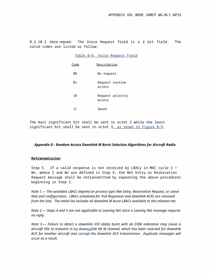
B.2.10.3 Voice request. The Voice Request field is a 2 bit field. The valid codes are listed as follow:
Table B-8 Voice Request Field
Code Description
00 No request
01 Request routine access
10 Request priority access
11 Spare
The most significant bit shall be sent in octet 2 while the least significant bit shall be sent in octet 3, as shown in Figure B-9.
Appendix D - Random Access Downlink M Burst Selection Algorithms for Aircraft Radio
Retransmission
Step 5. If a valid response is not received by LBACy in MAC cycle Z + Wn, where Z and Wn are defined in Step 4, the Net Entry or Reservation Request message shall be retransmitted by repeating the above procedures beginning in Step 2.
Note 1.— The available LBACs depend on process type (Net Entry, Reservation Request, or Leave Net) and configuration. LBACs scheduled for Poll Responses and downlink ACKs are removed from the lists. The initial list includes all downlink M burst LBACs available to the relevant net.
Note 2.— Steps 4 and 5 are not applicable to Leaving Net since a Leaving Net message requires no reply.
Note 3.— Failure to detect a downlink V/D (data) burst with an EOM indication may cause a aircraft VDL to transmit in an downuplink RA M channel, which has been reserved for downlink ACK for another aircraft and corrupt the downlink ACK transmission. Duplicate messages will occur as a result.
E.2.1.1 General. The interface between the XNI DCE and ATN Router DTE(s) shall conform to the ISO 8208 packet layer protocol. Accordingly, the XNI shall contain an ISO 8208 DCE.
Note. The ATN router contains a DTE.
E.2.2.2 MOBILE DTE ADDRESS
The mobile DTE address shall have a total length of 10 BCD digits, as follows:
X0 X1 X2 X3 X4 X5 X6 X7 X8 X9 (X0 shall be the most significant digit)
The digits X0 to X7 shall contain the ICAO 24 bit aircraft address coded in BCD. The digits X8 X9 received as XID parameter ADSA (Section E.10.1) shall identify a sub-address for a specific DTEs
APPENDIX VDL MODE 3AMCP WG-M/1 WP33
onboard an aircraft received as XID parameter (ADS E.10.1). This sub-address shall be in the range of 0 through 15. The following sub-address assignments shall be used:
00 ATN router01 to 15 Unassigned
E.5.1.3 PROCESSING OF M-BIT SEQUENCES
Note. M-bit processing is used for the orderly sequencing of reformatted DATA Packets.
M-bit sequence processing shall be applied on a per channel basis.
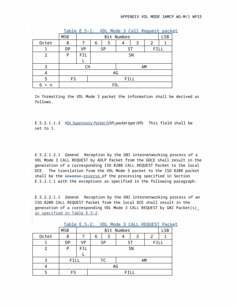
E.5.2.1.1.1 General. Reception by the ANI internetworking process of an ISO 8208 CALL REQUEST Packet from the local DCE shall result in the generation of a corresponding VDL Mode 3 CALL REQUEST by the ANI Packet as followsspecified in Table E.5-1:
Table E.5-1: VDL Mode 3 Call Request packetMSB Bit Number LSB
Octet 8 7 6 5 4 3 2 11 DP VP SP ST FILL2 P FILL SN3 CH AM4 AG5 FS FILL
6 + n FDv
In formatting the VDL Mode 3 packet the information shall be derived as follows.
E.5.2.1.1.3 VDL Supervisory Packet (VSP) packet type (VP). This field shall be set to 1.
E.5.2.1.2.1 General. Reception by the GNI internetworking process of a VDL Mode 3 CALL REQUEST by ADLP Packet from the GDCE shall result in the generation of a corresponding ISO 8208 CALL REQUEST Packet to the local DCE. The translation from the VDL Mode 3 packet to the ISO 8208 packet shall be the inverse reverse of the processing specified in Section E.5.2.1.1 with the exceptions as specified in the following paragraph.
E.5.2.2.1.1 General. Reception by the GNI internetworking process of an ISO 8208 CALL REQUEST Packet from the local DCE shall result in the generation of a corresponding VDL Mode 3 CALL REQUEST by GNI Packet(s) as specified in Table E.5-2.
Table E.5-2: VDL Mode 3 CALL REQUEST Packet
APPENDIX VDL MODE 3AMCP WG-M/1 WP33
MSB Bit Number LSBOctet 8 7 6 5 4 3 2 1
1 DP VP SP ST FILL2 P FILL SN3 FILL TC AM4 AG5 FS FILL
6 + n FDv
Fields shown in the packet format and not specified in the following paragraphs shall be set as specified in E.5.2.1.
E.5.2.2.1.6 Temporary channel number field (TC). This field shall be used to distinguish multiple call request from a GNI. The ANI internetworking process, upon receipt of a temporary channel number, shall assign a channel number from those presently in the Ready State, p1.
E.5.2.2.2.1 General. Reception by the ANI internetworking process of a VDL Mode 3 CALL REQUEST by GNI Packet from the ADCE shall result in the generation of a corresponding ISO 8208 CALL REQUEST Packet to the local DCE. The translation from the VDL Mode 3 packet to the ISO 8208 packet shall be the inverse reverse of the processing defined in E.5.2.2.1 with the exceptions as specified in the following paragraph.
E.5.2.3.1.1 General. Reception by the ANI Internetworking process of an ISO 8208 CALL ACCEPT Packet from the local DCE shall result in the generation of a corresponding VDL Mode 3 CALL ACCEPT by ANI Packet as followsspecified in Table E.5-3:.
Table E.5-3: VDL Mode 3 CALL ACCEPT PacketMSB Bit Number LSB
Octet 8 7 6 5 4 3 2 11 DP VP SP ST FILL2 TC SN3 CH AM4 AG
5 + n FDv
Fields shown in the packet format and not specified in the following paragraphs shall be set as specified in E.5.2.1
E.5.2.3.2.1 General. Reception by the GNI Internetworking process of a VDL Mode 3 CALL ACCEPT by ANI Packet from the GDCE shall result in the generation of a corresponding ISO 8208 CALL ACCEPT Packet to the local DCE. The translation from the VDL Mode 3 packet to the ISO 8208 packet shall be in the inreverse of the processing defined in the following paragraph.
APPENDIX VDL MODE 3AMCP WG-M/1 WP33
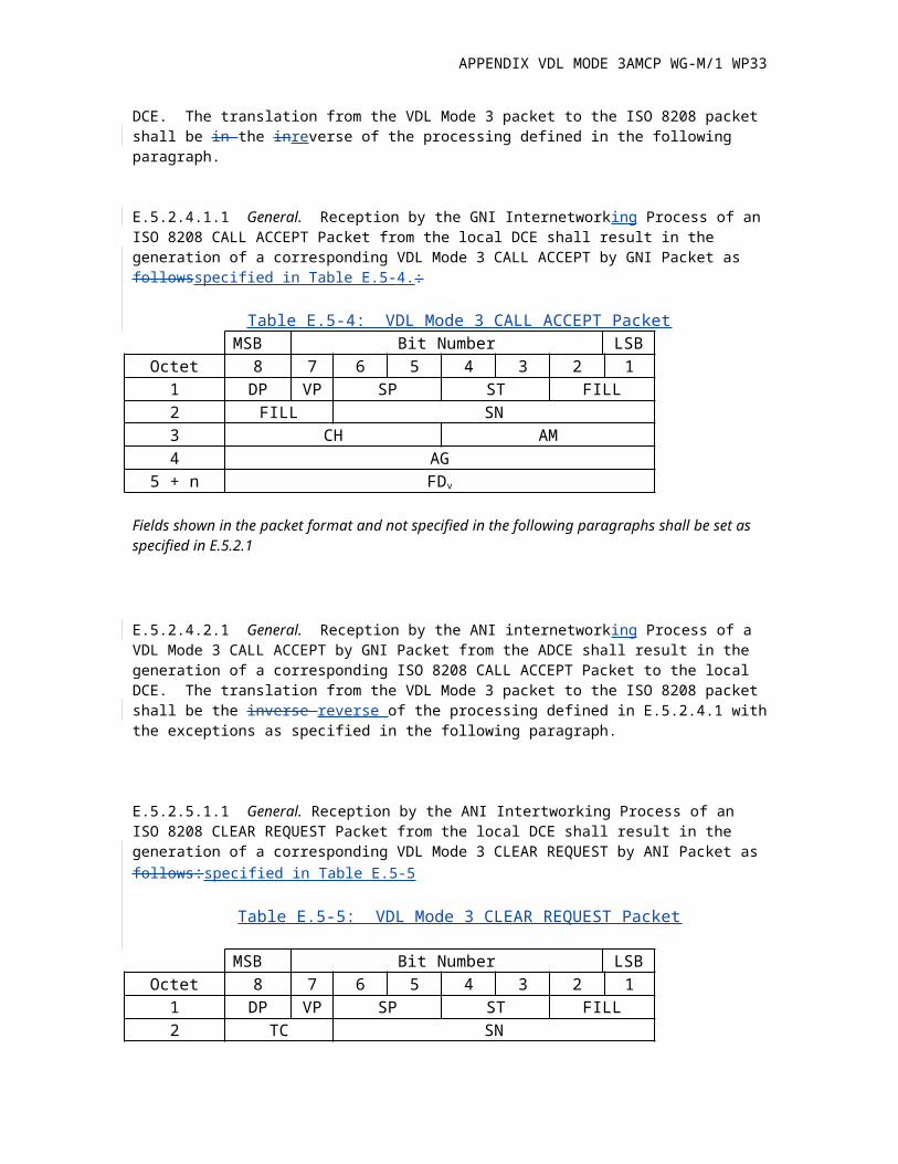
E.5.2.4.1.1 General. Reception by the GNI Internetworking Process of an ISO 8208 CALL ACCEPT Packet from the local DCE shall result in the generation of a corresponding VDL Mode 3 CALL ACCEPT by GNI Packet as followsspecified in Table E.5-4.:
Table E.5-4: VDL Mode 3 CALL ACCEPT PacketMSB Bit Number LSB
Octet 8 7 6 5 4 3 2 11 DP VP SP ST FILL2 FILL SN3 CH AM4 AG
5 + n FDv
Fields shown in the packet format and not specified in the following paragraphs shall be set as specified in E.5.2.1
E.5.2.4.2.1 General. Reception by the ANI internetworking Process of a VDL Mode 3 CALL ACCEPT by GNI Packet from the ADCE shall result in the generation of a corresponding ISO 8208 CALL ACCEPT Packet to the local DCE. The translation from the VDL Mode 3 packet to the ISO 8208 packet shall be the inverse reverse of the processing defined in E.5.2.4.1 with the exceptions as specified in the following paragraph.
E.5.2.5.1.1 General. Reception by the ANI Intertworking Process of an ISO 8208 CLEAR REQUEST Packet from the local DCE shall result in the generation of a corresponding VDL Mode 3 CLEAR REQUEST by ANI Packet as follows:specified in Table E.5-5
Table E.5-5: VDL Mode 3 CLEAR REQUEST Packet
MSB Bit Number LSBOctet 8 7 6 5 4 3 2 1
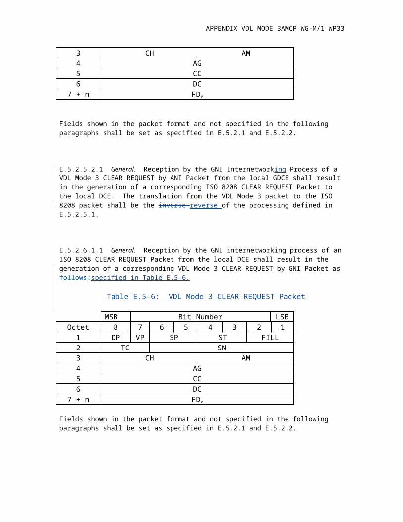
1 DP VP SP ST FILL2 TC SN3 CH AM4 AG5 CC6 DC
7 + n FDv
Fields shown in the packet format and not specified in the following paragraphs shall be set as specified in E.5.2.1 and E.5.2.2.
E.5.2.5.2.1 General. Reception by the GNI Internetworking Process of a VDL Mode 3 CLEAR REQUEST by ANI Packet from the local GDCE shall result in the generation of a corresponding ISO 8208 CLEAR REQUEST Packet to the local DCE. The translation from the VDL Mode 3 packet to the ISO 8208 packet shall be the inverse reverse of the processing defined in E.5.2.5.1.
APPENDIX VDL MODE 3AMCP WG-M/1 WP33
E.5.2.6.1.1 General. Reception by the GNI internetworking process of an ISO 8208 CLEAR REQUEST Packet from the local DCE shall result in the generation of a corresponding VDL Mode 3 CLEAR REQUEST by GNI Packet as follows:specified in Table E.5-6.
Table E.5-6: VDL Mode 3 CLEAR REQUEST Packet
MSB Bit Number LSBOctet 8 7 6 5 4 3 2 1
1 DP VP SP ST FILL2 TC SN3 CH AM4 AG5 CC6 DC
7 + n FDv
Fields shown in the packet format and not specified in the following paragraphs shall be set as specified in E.5.2.1 and E.5.2.2.
E.5.2.6.2.1 General. Reception by the ANI Intenetworking Process of a VDL Mode 3 CLEAR REQUEST by GNI Packet from the local ADCE shall result in the generation of a corresponding ISO 8208 CLEAR REQUEST Packet to the local DCE. The translation from the VDL Mode 3 packet to the ISO 8208 packet shall be the inverse reverse of processing defined in E.5.2.6.1.
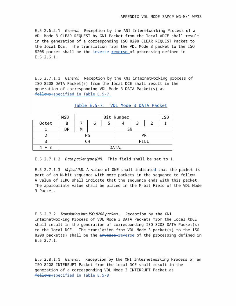
E.5.2.7.1.1 General. Reception by the XNI internetworking process of ISO 8208 DATA Packet(s) from the local DCE shall result in the generation of corresponding VDL Mode 3 DATA Packet(s) as follows:specified in Table E.5-7.
Table E.5-7: VDL Mode 3 DATA Packet
MSB Bit Number LSBOctet 8 7 6 5 4 3 2 1
1 DP M SN2 PS PR3 CH FILL
4 + n DATAv
E.5.2.7.1.2 Data packet type (DP). This field shall be set to 1.
E.5.2.7.1.3 M field (M). A value of ONE shall indicated that the packet is part of an M-bit sequence with more packets in the sequence to follow. A value of ZERO shall indicate that the sequence ends with this packet. The appropriate value shall be placed in the M-bit Field of the VDL Mode 3 Packet.
APPENDIX VDL MODE 3AMCP WG-M/1 WP33
E.5.2.7.2 Translation into ISO 8208 packets. Reception by the XNI Internetworking Process of VDL Mode 3 DATA Packets from the local XDCE shall result in the generation of corresponding ISO 8208 DATA Packet(s) to the local DCE. The translation from VDL Mode 3 packet(s) to the ISO 8208 packet(s) shall be the inverse reverse of the processing defined in E.5.2.7.1.
E.5.2.8.1.1 General. Reception by the XNI Internetworking Process of an ISO 8208 INTERRUPT Packet from the local DCE shall result in the generation of a corresponding VDL Mode 3 INTERRUPT Packet as follows:specified in Table E.5-8.
Table E.5-8: VDL Mode 3 INTERRUPT Packet
MSB Bit Number LSBOctet 8 7 6 5 4 3 2 1
1 DP VP SP ST FILL2 FILL SN3 CH FILL
4+n UDv
Fields shown in the packet format and not specified in the following paragraphs shall be set as specified in E.5.2.1.
E.5.2.8.2 Translation into ISO 8208 packets. Reception by the XNI Internetworking process of a VDL Mode 3 INTERRUPT Packet from the local XDCE shall result in the generation of a corresponding ISO 8208 INTERRUPT Packet to the local DCE. The translation from the VDL Mode 3 packet to the ISO 8208 packet shall be the inverse reverse of the processing defined in E.5.2.8.1.
E.5.2.9.1.1 General. Reception by the XNI Internetworking Process of an ISO 8208 INTERRUPT CONFIRMATION Packet from the local DCE shall result in the generation of a corresponding VDL Mode 3 INTERRUPT CONFIRMATION Packet as follows:specified in Table E.5-9.
Table E.5-9: VDL Mode 3 INTERRUPT Packet
MSB Bit Number LSBOctet 8 7 6 5 4 3 2 1
1 DP VP SP ST SS2 FILL SN3 CH FILL
Fields shown in the packet format and not specified in the following paragraphs shall be set as specified in E.5.2.1.
APPENDIX VDL MODE 3AMCP WG-M/1 WP33
E.5.2.9.2 Translation into ISO 8208 packets. Reception by the XNI Internetworking process of a VDL Mode 3 INTERRUPT CONFIRMATION Packet from the local XDCE shall result in the generation of a corresponding ISO 8208 INTERRUPT CONFIRMATION Packet to the local DCE. The translation from the VDL Mode 3 packet to the ISO 8208 packet shall be the inverse reverse of the processing defined in E.5.2.9.1.
E.5.2.10.1.1 General. Reception by the XNI Internetworking Process of an ISO 8208 RESET REQUEST Packet from the local DCE shall result in the generation of a corresponding VDL Mode 3 RESET REQUEST Packet as follows:specified in Table E.5-10.
Table E.5-10: VDL Mode 3 RESET REQUEST Packet
MSB Bit Number LSBOctet 8 7 6 5 4 3 2 1
1 DP VP SP ST FILL2 FILL SN3 CH FILL4 RC5 DC
Fields shown in the packet format and not specified in the following paragraphs shall be set as specified in E.5.2.1.
E.5.2.10.2 Translation into ISO 8208 packets. Reception by the XNI Internetworking process of a VDL Mode 3 RESET REQUEST Packet from the local XDCE shall result in the generation of a corresponding ISO 8208 RESET REQUEST Packet to the local DCE. The translation from the VDL Mode 3 packet to the ISO 8208 packet shall be the inverse reverse of the processing defined in E.5.2.10.1.
E.5.3.1.1 General. The VDL Mode 3 RECEIVE READY Packet arriving from the XNI is not related to the control of the DTE/DCE interface and shall not cause the generation of an ISO 8208 packet. The format of this packet shall be as follows:specified in Table E.5-11.
Table E.5-11: VDL Mode 3 RECEIVE READY Packet
MSB Bit Number LSBOctet 8 7 6 5 4 3 2 1
1 DP VP SP ST FILL2 FILL SN3 CH PR
Fields shown in the packet format and not specified in the following paragraphs shall be set as specified in E.5.2.1. The packet shall be processed as specified in E.6.5.
APPENDIX VDL MODE 3AMCP WG-M/1 WP33
E.5.3.2.1 General. The VDL Mode 3 RECEIVE NOT READY Packet arriving from the XNI is not related to the control of the DTE/DCE interface and shall not cause the generation of an ISO 8208 packet. The format of this packet shall be as specified in Table E.5-12.follows:
Table E.5-12: VDL Mode 3 RECEIVE NOT READY Packet
MSB Bit Number LSBOctet 8 7 6 5 4 3 2 1
1 DP VP SP ST FILL2 FILL SN3 CH PR
Fields shown in the packet format and not specified in the following paragraphs shall be set as specified in E.5.2.1. The packet shall be processed as specified in E.6.65.
E.5.3.3.1 General. The format of this packet shall be as specified in Table E.5-13.follows:
Table E.5-13: VDL Mode 3 CLEAR CONFIRMATION Packet
MSB Bit Number LSBOctet 8 7 6 5 4 3 2 1
1 DP VP SP ST FILL2 TC SN3 CH AM4 AG
Fields shown in the packet format and not specified in the following paragraphs shall be set as specified in E.5.2.1 and E.5.2.5. The packet shall be processed as specified in E.6.3.
E.5.3.4.1 General. The format of this packet shall be as specified in Table E.5-14.follows:
Table E.5-14: VDL Mode 3 RESET CONFIRMATION Packet
MSB Bit Number LSBOctet 8 7 6 5 4 3 2 1
1 DP VP SP ST FILL2 FILL SN3 CH FILL
Fields shown in the packet format and not specified in the following paragraphs shall be set as specified in E.5.2.1. The packet shall be processed as specified in E.6.7.
E.5.3.5.1 General. The format of this packet shall be as follows:specified in Table E.5-15.
Table E.5-15: VDL Mode 3 REJECT Packet
APPENDIX VDL MODE 3AMCP WG-M/1 WP33
MSB Bit Number LSBOctet 8 7 6 5 4 3 2 1
1 DP VP SP ST SS2 FILL SN3 CH PR
Fields shown in the packet format and not specified in the following paragraphs shall be set as specified in E.5.2.1. The packet shall be processed as specified in E.6.8.
E.6.4.4.5 Next in sequence, within the window. When the sequence number (PS) of the packet received is next in sequence and within the window, the XDCE shall accept this packet. Receipt of a packet with shall be considered an error if it contains a sequence number (PS)
a) outside the window, orb) out of sequence, orc) not equal to zero for the first data packet after entering Flow control Ready stateshall be considered an error.
E.7.2.1 Multiplexing header. The header for the multiplexed packets shall be as specified in Table E-7.1.follows:
Table E.7-1: Multiplexing Header Packet Structure
MSB Bit Number LSBOctet 8 7 6 5 4 3 2 1
1 DP VP SP ST FILL
Where,Data packet type (DP) = 0.VDL VSP Packet type (VP) = 1.Supervisory packet (SP) = 3.Supervisory type (ST) = 2.
E.8.1 Ground subnetwork address – DTE address correlation
The ANI shall construct and manage a VDL Mode 3 Ground Subnetwork Address – DTE cross reference table whose entries are the VDL Mode 3 data link Ground Subnetwork Address and the ground DTE address associated with the ground ATN router. This table is used to maintain the connection context to associate link layer PDUs with the appropriate SVC, as well as providing a means to maintain a connection through an old SVC while establishing a new SVC during handoff. Each entry of the cross reference table shall consist of the 6 bit Ground Subnetwork Address and the 8 bit binary representation of the Ground DTE.
Table E.10-1 ADSA Parameter

APPENDIX VDL MODE 3AMCP WG-M/1 WP33
Parameter ID 0 1 10 0 0 0 10 0 10 ADSA parameter
Parameter Length 0 0 0 0..................................................................................0 0 0 1
Parameter Value v8v7v6v5 v4v3v2v1
Table E.10-2 GDTE Parameter
Parameter ID 0 1 0 01 0 0 1 1 0 1 GDTE parameter
Parameter Length 0 0 0 0..................................................................................0 0 0 1
Parameter Value v8v7v6v5 v4v3v2v1
Table E.10-3 VER Parameter
Parameter ID 0 1 0 01 0 0 1 1 0 VER parameter
Parameter Length 0 0 0 0 0 0 0 1
Parameter Value v8v7v6v5 v4v3v2v1
Table E.10-4 MBIT Parameter
Parameter ID 0 1 0 01 0 1 0 1 01 M-BIT parameter
Parameter Length 0 0 0 0 ............................................................................................0 0 1 0
Parameter Value v16v15v14v13 v12v11v10v09
V08v07v06v05 v04v03v02v01
F.1.1.8 Bit field. The Bit Field, as well as the Q bit of Section F.1.1.3, shall be as defined in Figure F-4.
APPENDIX VDL MODE 3AMCP WG-M/1 WP33
Bit Meaning (Present == 1)Q QOS Options PresentS SP flag of CLNP Header - Data Unit Identifier PresentE Compliment of CLNP Error Flag (ER) flag M More Segments (MS) bit of CLNP HeaderT Sequence vs. Transit Delay Bit (from QOS Option)H Lifetime Field present (Hop Count)O Segment Offset PresentL Total Length field presentD Type of PDU (Error = 1, Data = 0)
Figure 0F-4. Bit Field Definitions
F.1.1.11 Segment Offset. The Segment Offset shall be sent whenever the Segmentation Permitted (SP) bit is set and the Segment Offset is greater than zero. The presence of the Segment Offset field shall be indicated by the O bit.
EF.1.2.3 Restart Packets On reception of a restart packet all index numbers that have been assigned by the receiving entity, and the information referenced by the index numbers, (e.g., NSAP pair) shall be deleted. For a ground VDL Mode 3 installation deletion shall be restricted to the index information associated with the aircraft originating the restart packet.
Note. A compressor has two sets of index numbers. Those assigned by the compressor and those assigned by its peer. Reception of a restart packet only applies to the index numbers used for decompressing, i.e., the index numbers assigned by the remote peer.
F.2 Compression rules
Note. The following compression and decompression rules are for both the air and ground VDL Mode 3 equipment. It is assumed that both require broadcast compression (although the usefulness of aircraft VDL Mode 3 broadcasting has yet to be determined).
If the CLNP version field is not 1, the packet shall be sent as TYPE_CLNP. If the CLNP packet is of any type other than Data or Error, the packet shall be sent as
TYPE_CLNP.Note. It has now been determined that this packet is suitable for compression. If the NSAP pair has not been associated with an index number, the CLNP packet shall be sent
as TYPE_UNCOMPRESSED_CLNP.
If the link is simplex, the packet is not TYPE_MULTICAST, and the last CT1 (System Parameter) packets for this index/pair association have been sent as compressed type, or CT2 (system parameter) seconds have passed since the last packet with this index number has been sent, the packet shall be sent as TYPE_UNCOMPRESSED_CLNP.
If the security option is not coded as specified for ATN traffic, the CLNP packet shall be sent as TYPE_COMPRESSED_CLNP_LONG_WITH_OPTIONS. The security and other non-compressed options shall be copied into the options portion of the compressed header.
APPENDIX VDL MODE 3AMCP WG-M/1 WP33
If the priority option is present with a value greater than 14, the CLNP packet shall be sent as TYPE_COMPRESSED_CLNP_LONG_WITH_OPTIONS. The priority and other non-compressed options shall be copied into the options portion of the compressed header.
If the CLNP packet SP bit is zero, the lifetime field has a value of greater than hexadecimal 1c on downlinks or is less than 5 on uplinks, the S/T bit is not set, the packet type is DT, the ER bit is non-zero, and no options are present other than security, QOS, Security, or Priority, the packet shall be sent as TYPE_COMPRESSED_SHORT.
Note 1. Many CLNP installations include the segment information fields even when the packet is unsegmented. It is thus necessary to check for this condition.
Note 2. At this point, the packet compression type must be long.
If a CLNP option is present which is not QOS, security, priority, or padding, the packet shall be sent as TYPE_COMPRESSED_CLNP_LONG_WITH_OPTIONS. The options shall be copied into the options portion of the compressed header.
Otherwise the packet shall be sent as TYPE_COMPRESSED_CLNP_LONG_NO_OPTIONS
For the compressed long packets, the Lifetime field shall be included when its value is greater than 5, or less than hexadecimal 1d. The DUI field shall be included when the packet is segmented. The Segment Offset field shall be included when it is non-zero and the SP bit from the CLNP header is set. The Total Length field shall be included if this is the first time this DUI is being compressed. The Options fields that are not QOS, priority, security, or padding shall be included unmodified. The T, M, and S fields shall be set to the corresponding values of the S/T, MS and SP values in the original packet. The E fields shall be set to the reverse inverse (complimentcomplement) of the ER value. The Discard Reason field shall be set if the packet is an Error PDU.
Table F-1 CT1 Parameter
Parameter ID 0 1 0 0 1 0 0 0 1 10 Multicast Packet Period
Parameter Length 0 0 0 0 0 0 0 1
Parameter Value v8 v7 v6 v5 v4 v3 v2 v1
Table F-2 CT2 Timer
Parameter ID 0 1 0 0 1 0 0 0 1 1 Multicast Refresh Timer
Parameter Length 0 0 0 0 0 0 1 0
Parameter Value v16 v15 v14 v13 v12 v11 v10 v9
v8 v7 v6 v5 v4 v3 v2 v1
APPENDIX VDL MODE 3AMCP WG-M/1 WP33
Table F-3 CT3 Timer
Parameter ID 0 1 0 0 1 0 0 1 1 0 0 Index Idle Timer
Parameter Length 0 0 0 0 0 0 0 1
Parameter Value v16 v15 v14 v13 v12 v11 v10 v9
v8 v7 v6 v5 v4 v3 v2 v1